1
Operation
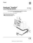
RoadLazer™ RoadPak™
Line Striping System
3A1214B
ENG
- For the Application of Road Marking and Reflective Coatings - For Professional Use Only List of Models (see page 2)
2900 psi (20 MPa, 200 bar) Maximum Working Pressure
Important Safety Instructions
Read all warnings and instructions in this
manual. Save these instructions.
ti15835a
Models
Models
Ref.
Model Number
Description
1
24G624
1 Pump RoadPak
2
24G625
2 Pump RoadPak
3
24G626
Single Hitch Mounting Frame
4
24G627
RoadPak Slide in Mounting Frame
5
24G628
1 Pump RoadPak Gun Arm
6
24G629
2 Pump RoadPak Gun Arm
7
24G630
Gun Arm Beam
8
24G632
RoadLazer/RoadPak Control
9
24G633
Road View Camera System
10
24G634
RoadPak Pointer System
Complete Assemblies
Part Number
2
Description
24G677
RoadPak System Option 1 (1, 3, 5, 7, 8, 10)
24G679
RoadPak System Option 2 (1, 3, 5, 7, 8, 9, 10)
24G681
RoadPak System Option 3 (1, 4, 5, 7, 8, 10)
24G683
RoadPak System Option 4 (1, 4, 5, 7, 8, 9, 10)
24G685
RoadPak System Option 5 (2, 3, 6, 7, 8, 10)
24G687
RoadPak System Option 6 (2, 3, 6, 7, 8, 9, 10)
24G689
RoadPak System Option 7 (2, 4, 6, 7, 8, 10)
24G691
RoadPak System Option 8 (2, 4, 6, 7, 8, 9, 10)
3A1214B
Warnings
Warnings
The following warnings are for the setup, use, grounding, maintenance, and repair of this equipment. The exclamation point symbol alerts you to a general warning and the hazard symbols refer to procedure-specific risks. When
these symbols appear in the body of this manual, refer back to these Warnings. Product-specific hazard symbols and
warnings not covered in this section may appear throughout the body of this manual where applicable.
WARNING
WARNING
FIRE AND EXPLOSION HAZARD
Flammable fumes, such as solvent and paint fumes, in work area can ignite or explode. To help prevent fire
and explosion:
• Use equipment only in well ventilated area.
• Do not fill fuel tank while engine is running or hot; shut off engine and let it cool. Fuel is flammable and can
ignite or explode if spilled on hot surface.
• Eliminate all ignition sources; such as pilot lights, cigarettes, portable electric lamps, and plastic drop cloths
(potential static arc).
• Keep work area free of debris, including solvent, rags and gasoline.
• Do not plug or unplug power cords, or turn power or light switches on or off when flammable fumes are
present.
• Ground all equipment in the work area. See Grounding instructions.
• Use only grounded hoses.
• Hold gun firmly to side of grounded pail when triggering into pail.
• If there is static sparking or you feel a shock, stop operation immediately. Do not use equipment until you
identify and correct the problem.
• Keep a working fire extinguisher in the work area.
SKIN INJECTION HAZARD
High-pressure fluid from dispensing device, hose leaks, or ruptured components will pierce skin. This may look
like just a cut, but it is a serious injury that can result in amputation. Get immediate SURGICAL TREATMENT.
+
•
•
•
•
•
•
•
Keep clear of fluid outlet and leaks.
Use guns, hoses and other components with pressure ratings equal to or higher than the pump rating.
Follow the Pressure Relief Procedure before servicing or cleaning.
Do not point dispensing device at anyone or at any part of the body.
Do not stop or deflect leaks with your hand, body, glove, or rag.
Tighten all fluid connections before operating the equipment.
Check hoses and couplings daily. Replace worn or damaged parts immediately.
MOVING PARTS HAZARD
Moving parts can pinch, cut or amputate fingers and other body parts.
• Keep clear of moving parts.
• Do not operate equipment with protective guards or covers removed.
• Pressurized equipment can start without warning. Before checking, moving, or servicing equipment, follow
the Pressure Relief Procedure and disconnect all power sources.
3A1214B
3
Warnings
WARNING
WARNING
EQUIPMENT MISUSE HAZARD
Misuse can cause death or serious injury.
• Do not operate the unit when fatigued or under the influence of drugs or alcohol.
• Do not exceed the maximum working pressure or temperature rating of the lowest rated system component.
See Technical Data in all equipment manuals.
• Use fluids and solvents that are compatible with equipment wetted parts. See Technical Data in all
equipment manuals. Read fluid and solvent manufacturer’s warnings. For complete information about your
material, request MSDS from distributor or retailer.
• Do not leave the work area while equipment is energized or under pressure. Turn off all equipment and
follow the Pressure Relief Procedure when equipment is not in use.
• Check equipment daily. Repair or replace worn or damaged parts immediately with genuine manufacturer’s
replacement parts only.
• Do not alter or modify equipment.
• Use equipment only for its intended purpose. Call your distributor for information.
• Route hoses and cables away from traffic areas, sharp edges, moving parts, and hot surfaces.
• Do not kink or over bend hoses or use hoses to pull equipment.
• Keep children and animals away from work area.
• Comply with all applicable safety regulations.
CARBON MONOXIDE HAZARD
Exhaust contains poisonous carbon monoxide, which is colorless and odorless. Breathing carbon monoxide
can cause death.
• Do not operate in an enclosed area.
TOXIC FLUID OR FUMES HAZARD
Toxic fluids or fumes can cause serious injury or death if splashed in the eyes or on skin, inhaled, or swallowed.
• Read MSDSs to know the specific hazards of the fluids you are using.
• Store hazardous fluid in approved containers, and dispose of it according to applicable guidelines.
BURN HAZARD
Equipment surfaces and fluid that’s heated can become very hot during operation. To avoid severe burns:
• Do not touch hot fluid or equipment.
PERSONAL PROTECTIVE EQUIPMENT
You must wear appropriate protective equipment when operating, servicing, or when in the operating area of
the equipment to help protect you from serious injury, including eye injury, hearing loss, inhalation of toxic
fumes, and burns. This equipment includes but is not limited to:
• Protective eyewear, and hearing protection.
• Respirators, protective clothing, and gloves as recommended by the fluid and solvent manufacturer.
4
3A1214B
Introduction and General Information
Introduction and General Information
Introduction
Front Guidance System
This manual and those listed below provide pre-setup
requirements, parts lists, setup, operation, and maintenance instructions for the RoadLazer system. This manual includes instructions for a 2-pump system. For
1-pump systems, all parts remain the same with the
exception of plugged ports for missing pumps and
hoses.
The Front Mechanical Guidance System provides the
user with a pointer for alignment on either the left or right
side of the vehicle.
General Information
The RoadLazer is mounted to a vehicle and is used to
stripe up to two stripes in one or two colors with glass
beading.
Video Guidance System™ (optional)
The Video Guidance System provides the user with
video of a bore sight view for alignment on either the left
or right side of the tow vehicle. The system consists of a
9 in. monitor, interfacing cables, video camera and
mounting bracket.
RPS 2900 Hydraulic Pumps
The RoadLazer consists of a Programmable Skipline
Controller, Displacement Pumps, two Paint Spray Guns,
and two Bead Spray Guns.
The RPS 2900 Hydraulic Pump supplies paint to the
spray guns. There are two displacement pumps. Two
displacement pumps allows the user to have a two-color
system.
Programmable Skipline Controller
Paint Spray Guns
The Programmable Skipline Controller consists of the
control box and a 30 ft cable. It is the main control for the
RoadLazer system and turns the spray guns and accessories on and off.
The Paint Spray Guns are pneumatically triggered to
spray paint stripes when commanded by the Programmable Skipline Controller.
Bead Spray Guns
The Bead Spray Guns are pneumatically triggered to
spray reflective materials when commanded by the Programmable Skipline Controller.
3A1214B
5
Component Identification
Component Identification
A
Y
X
W
B
T
C
D
S
R
E
F
G
H
N
P
Q
J
K
L
M
AA
AB
Z
AC
AH
AE
ti15836a
AJ
AD
AG
6
AF
3A1214B
Component Function
Component Function
A
Air Regulator
Allows regulation of the bead tank air pressure
B
Bead Tank
Holds up to 36 gallons of reflective materials or element for single or double drop
beading
C
Air Accumulator Tank
Helps reduce air temperature from compressor
D
Hydraulic Valve
Valve to shut off/on the hydraulic fluid to the hydraulic motor
E
Fluid Filter
Filters fluid between the fluid source and the spray gun
F
Pressure Drain Valve
Relieves Fluid Pressure when open
G
RPS 2900 Hydraulic Pump
Provides fluid to be sprayed through the spray gun
H
Fluid Outlet
Supplies fluid from the displacement pump to the spray gun
J
Fluid Inlet
Displacement Pump entry for fluid from the paint drums (paint drums not shown)
K
Electrical Junction Box
Allows the user access to electrical system
L
18 HP Engine
Powers the hydraulic pump and the air compressor
M
2 in. Hitch Receiver (not provided)
Needed to hook-up the gun arm to the back of a truck
N
Fuel Tank
Holds 6 gallons (23 liters) of gasoline
P
Hydraulic Pressure Control Knob
Provides adjustment of hydraulic pressure (clockwise increases pressure)
Q
Battery
Provides power to start the Engine and Control Box
R
Compressor
Provides an air supply for the solenoids and pressurizes the bead tanks
S
Hydraulic Reservoir
Holds 4 gallons (15.1 liters) of hydraulic oil for the hydraulic pump
T
I/O Cable
Carries electronic control signals from the Controller to the RoadLazer
W
Programmable Skipline Controller
Allows the user to program the operation of the RoadLazer
X
Breather Cap
Provides a means for hydraulic reservoir ventilation, oil check, and fill
Y
Air Pressure Quick Release
Allows the user to use pressurized air
Z
Hitch Insert
Allows the user to connect the gun arm to a single hitch vehicle
AA
Mounting Bracket
Allows the user to connect the gun arm mount to the optimum height
AB
Stow Bracket Pin
Secures the spray gun boom arm when the RoadLazer is in transport mode
AC
Gun Arm Mount
Supports the main beam and the gun arm
AD
Slide Beam
Supports the spray gun boom arm
AE
Spray Gun Boom Arm
Allows striping on either side of the vehicle at adjustable distances
AF
Bead Spray Gun
Sprays beads when commanded by the Controller
AG
Paint Spray Gun
Sprays fluid when controller by the Controller
AH
Slide in Mounting Frame
Allows user to connect the gun arm to the RoadPak frame
AJ
RoadPak Pointer System
Allows the user an alignment tool
3A1214B
7
Setup
Setup
Charge Battery
The RoadPak can be mounted in the front or rear of the
vehicle bed as well as in any orientation desired. The
base of the RoadPak is 39.5 in. x 49.5 in. (1.0m x
1.25m).
If the battery is newly purchased or has not been used
for a long time, charge it before you use it.
Installing RoadLazer Into Vehicle
ti16653a
RoadLazer needs to be properly secured to prevent it
from moving during transportation and operation.
Paint drums are heavy and could shift from side to side
when the vehicle is cornering. The paint drums could
fall from the vehicle and cause injury or death. Secure
the drums when the vehicle is in transport or spraying.
Paint could splash from the paint drum bung adapters
when the paint drums are full and the vehicle is moving. Do not overfill the paint drums.
ti16654a
RoadPak Installation
(24G624, 24G625)
Load RoadPak into vehicle using a forklift or a hoist that
is rated for the weight capacity of the RoadPak. For
RoadPak weight information see Technical Data, page
27.
ti16664a
After mounting the RoadPak on the vehicle, firmly
secure the RoadPak to the vehicle using the tie-down
brackets at all four corners, or by bolting the RoadPak
through the bed of the truck to the frame in all four locations.
ti16442a
ti16443a
ti16665a
ti16599a
8
3A1214B
Setup
Filter Orientation
After mounting and securing the RoadPak to the vehicle,
position the filter assemblies as desired.
2. Tighten nut until the hitch insert bracket is pulled
securely to the receiver and no play is seen
between the two parts.
1. Use a hammer to loosen the large jam nut on the
pump assembly.
ti16785a
3. Install the height adjustment bracket (303) to the
hitch insert bracket with bolts (312), washers (307),
and nuts (315). Ensure the height adjustment
bracket is installed level.
ti16782a
2. Rotate the filter assembly to the desired orientation
and use a hammer to tighten the jam nut and lock
the assembly into place.
315
307
307
312
ti16783a
ti16784a
Gun Arm Bracket Mount
Single Hitch Mounting Bracket (24G626)
Installation (Option 1)
303
ti15956a
4. Install stow bracket (302) to height adjustment
bracket (303) with bolts (312), washers (307), and
nuts (315). Locate the bottom of the stow-bracket
21-in. to 25-in. (53cm - 63cm) from the ground.
Ensure the stow-bracket is installed level.
315
307
312
ti15839a
1. Install hitch insert bracket (A) into receiver (C).
Ensure hitch pin (B) goes through tightening rod
hole (D).
302
302
ti16648a
A
D
B
3A1214B
21 in. - 25 in.
(53 cm - 63 cm)
C
ti15955a
ti15957a
9
Setup
RoadPak Mounting Bracket (24G627)
Installation (Option 2)
1. Slide the RoadPak mounting arms (304) between
the two fork lift channels in the frame.
304
ti16917a
ti16441a
NOTE: Cutting the RoadPak mounting arms and bolting
them through the bed to the frame of the vehicle is an
option in addition to the following mounting techniques:
2. Depending on where the RoadPak is located on the
vehicle determines which holes to bolt through on
the RoadPak frame. There are 8 possible mounting
holes for each mounting arm. Fasten to at least two
holes on each side.
ti16659a
ti16661a
3. Hand-tighten bolts (312), nuts (315), and washers
(307) to mounts.
Narrow Orientation
312
307
315
ti16660a
ti16656a
10
3A1214B
Setup
4. Install the height adjustment bracket (303) to the
RoadPak mounting arms (304) with bolts (312),
washers (307), and nuts (315).
NOTE: It is recommended to bolt the mounting
bracket through the bed of the vehicle to the frame
of the vehicle.
315
312
307
ti16912a
303
ti16916a
5. Use wrench to tighten all bolts to lock into place
(torque to 28 ft-lb).
6. Install stow-bracket (302) to height adjustment
bracket (303). Locate the bottom of the stow-bracket
21 in. to 25 in. (53cm - 63cm) from the ground.
Ensure the stow-bracket is installed level.
302
21 in. - 25 in.
53 cm - 63 cm
ti16787a
3A1214B
11
Setup
Wide Orientation
3. Install the height adjustment bracket to the RoadPak
mounting arms (303).
315
312
307
303
ti16921a
ti16657a
1. Bolt brackets (316) to the RoadPak in four locations
with bolts (312), washers (307), and nuts (315). It is
ideal to locate the brackets as far apart as possible
to provide optimal support. The mounting location of
the brackets will depend on where the RoadPak is
mounted on the vehicle.
4. Use wrench to tighten all bolts to lock into place
(torque to 28 ft-lb).
315
316
307
ti16786a
318
2. Slide the RoadPak mounting brackets (304) through
the cut out holes in the frame and hand-tighten the
mounting arms to the brackets with bolts (312),
washers (307), and nuts (315).
ti16924a
316
304
ti16911a
315
307
ti16913a
12
312
3A1214B
Setup
5. Install stow-bracket (302) to height adjustment
bracket (303). Locate the bottom of the stow-bracket
21 in. to 25 in. (53cm - 63cm) from the ground.
Ensure the stow-bracket is installed level.
1. To shorten the beam to 75.75 in. long, cut 12 in.
from the end the beam towards the next hole on the
beam. To shorten the beam to 60 in., cut 27.75 in.
from the end of the beam towards the third hole as
shown below.
27.75 in.
12 in.
ti16960a
ti16600a
302
2. After determining the desired length, slide the beam
into the bracket on the channel.
21 in. - 25 in.
53 cm - 63 cm
ti16787a
ti16647a
NOTE: It is recommended to bolt the mounting
bracket through the bed of the vehicle to the frame
of the vehicle.
Gun Arm Installation (24G628, 24G629)
1. Position the gun arm assembly next to the vehicle.
2. Pull the slide beam out to the side of the vehicle
where the gun arm is located. Lift the gun arm and
hold the traverse bracket in the position shown
below. Slide the beam through the wheels so they
are mounted on the track of the slide beam as
shown below.
ti16916a
Slide Beam Installation (24G630)
The slide beam is 87.75 in. (2.2m) long. The Slide Beam
is shipped to accommodate wider vehicles. The beam
can be cut down to 75.75 in. (1.9m) long or 60 in. (1.5m)
long to accommodate different vehicle sizes.
ti15959a
3A1214B
13
Setup
3. Attach the handle (702) to each end of the slide
beam. Press the cotter pin (707) through the handle
to hold it in place. Fasten nut (706) and bolt (705)
through the slide beam on both ends to act as stops
on the channel.
6. Lift gun arm to a vertical position and slide it over
the stow bracket.
708
707
704
706
ti16422a
705
ti16662a
4. Route hoses for the gun arm before moving arm to
prevent hoses from being pinched.
7. Rest the gun arm on the stow bracket and position
the stop to sit properly on the stow bracket. Slide the
pin (321) through the gun arm bracket and stow
bracket to secure the gun arm. Tighten the two bolts
(579) down to lock the gun arm bracket into place.
579
ti16658a
5. Position gun arm at the end of the slide beam and
secure the hose bundle to the height adjustment
bracket with a rubber pad and hose clamp (320).
ti15837a
302
ti16918a
ti16788a
14
3A1214B
Setup
Hose Routing to Pumps and Tanks
ti16548a
3A1214B
15
Setup
Hose Routing
Hose Connection
1. Pull slide beam out to one side of the vehicle. Pull
gun arm out and lower it to make sure the hose bundle has been secured at the proper location to
ensure full movement for the gun arm to move from
one side to the other. Make adjustments to the hose
clamp that secures the bundle as needed.
1. Install suction tubes to the RPS 2900 pump and
route to paint drum.
ti16445a
ti16444a
2. Install return line from the RPS 2900 filter assembly
and route back to the paint drum.
ti16658a
2. Lift gun arm back to the stow position. Pull slide
beam out to other side of vehicle and pull the gun
arm to that side to ensure the hose length is adequate for full movement.
ti16597a
3. Install paint lines to RPS 2900 filter assemblies. For
a two color system, route the hose from paint gun 1
to pump 1 and route one hose from paint gun 2 to
pump 1. Route the second hose from paint gun 2 to
pump 2.
ti16655a
3. Put gun arm back to the stow position and pin it into
place. Center the slide beam to the vehicle. Lock the
slide beam and gun arm into place by engaging the
clamps for each.
ti16446a
4. Install bead lines to the bead tank.
ti15954a
ti16598a
16
3A1214B
Setup
5. Install air hose to quick connect fitting on air tank.
2. Connect control cable to the junction box. Fasten
cable to cable clamp for strain relief (S) on the connection.
ti16914a
ti16595a
Electrical Cable Connections
1. Connect gun arm cable to the junction box. Fasten
cable to cable clamp for strain relief (S) on the connection.
ti16596a
3A1214B
S
S
3. Route the control cable to the cab of the vehicle
without pinching the cable. Connect the cable to the
control box. Route cable through the cable clamp for
strain relief on the connection.
ti16601a
17
Setup
Install Front Pointer Instructions
1. Locate an area on the vehicle to mount the RoadPak pointer system that will allow the user to see the
indicator rod from the driving position or with the
help of the Road View Camera System.
5. Slide support bar (351) through brackets (355) and
tighten fasteners to secure in place.
355
351
ti17000a
6. Assemble extension clamp to support bar.
ti16408a
ti16925a
2. If needed, drill two 9/16 in. holes in the desired location.
3. Assemble mounting bracket (355) to desired location with bolt (359), washer (360), and nut (361).
361
7. Insert indicator rod (362) into guide extension arm
(352) and secure in place with knob(354).
8. Adjust the indicator rod by loosening extension
clamps and sliding the guide extension arm (352) to
desired position. Secure by tightening knob (354).
Install and Align Front Mechanical
Guidance System (Optional)
360
355
See Guidance System manual.
359
ti16927a
4. Hand tighten lock bar (6) to mounting bracket (355)
with bolts (357) and nuts (358).
Install and Align Video Guidance System
(Optional)
See RoadView Camera System manual.
Install Winch Kit (Optional)
358
See Winch Kit manual.
6
357
ti16926a
18
3A1214B
Operation
Operation
Pressure Relief Procedure
4. Relieve hose pressure through guns. Use Programmable Skipline Controller to trigger each gun for at
least 3 seconds each.
INJECTION HAZARD
The system pressure must be manually relieved to prevent the system from starting or spraying accidentally.
Fluid under high pressure can be injected through the
skin and cause serious injury. To reduce the risk of an
injury from injection, splashing fluid, or moving parts,
follow the Pressure Relief Procedure whenever you:
•
are instructed to relieve the pressure
•
stop spraying
•
check or service any of the system equipment
•
install or clean the spray tip
NOTE: Always relieve pressure with the guns--not
with the filter drain valves.
5. Close paint gun ball valves.
ti15953a
6. Open all drain valves, one at a time.
FIRE AND EXPLOSION HAZARD
When Flushing system, always connect grounding
cord.
RPS 2900 Pump Fluid Pressure Relief
1. Set hydraulic valve to OFF position.
7. Close valves immediately to prevent paint from drying in system.
NOTE: If you suspect that the spray gun or hose is completely clogged, or that pressure has not been fully
relieved after following the steps above, very slowly
loosen the hose end coupling, and relieve pressure
gradually. Then loosen it completely. Then clear the
valve or hose.
Bead System Pressure Relief
1. Relieve air pressure in bead tank by turning bead
system valve to OFF position.
ti15838a
2. Run engine at half throttle.
3. Place empty pail under paint guns to catch drainage.
3A1214B
ti16550a
19
Operation
Air System Pressure Relief
1. Relieve air pressure in air tank by turning air valve to
OPEN position.
2. Pull slide beam to left or right side of vehicle. Lock
slide beam clamps.
3. Remove gun arm from upright stowed position, and
slide to end of boom. Slowly lower gun arm, and
lock into position with clamp.
ti16961a
EMERGENCY SHUT OFF
To shut down the entire RoadLazer system, set POWER
ON/OFF on the Programmable Skipline Controller to the
OFF position.
ti16423a
Prepare System to Paint
Load Reflecting Materials
1. Set POWER ON/OFF on Programmable Skipline
Controller to OFF.
Initial Settings
1. Ground RoadLazer ground strap to earth ground.
2. Set RoadLazer engine ignition key to OFF.
3. Relieve air system pressure by opening ball valve
until gauge reads 0.
4. Relieve air pressure in bead tank by turning bead
system valve to OFF position.
5. Remove cover from bead tank.
TI3058A
6. Screen reflective materials to prevent debris from
entering tank.
7. Load bead tank with reflective materials.
2. Fill throat packing nut with TSL to prevent premature
packing wear. Do this each time you spray and
store.
Set Up Slide Beam and Gun Arm
1. Unlock gun arm clamp and slide beam clamps.
Approximate
Fill Level
ti5240a
ti16425a
20
3A1214B
Operation
3. Check engine oil level. Add SAE 10W-30 (summer)
or 5W-20 (winter), if necessary.
9. Turn pump lever by guns clockwise 1/4 turn to OFF
position.
(cold)
ti15953a
ti16447a
4. Fill fuel tank.
10. Place suction tube and drain tube in grounded metal
pail partially filled with flushing fluid. Attach ground
wire to pail and to earth ground.
5. Check hydraulic oil level. Add only Graco Hydraulic
Oil, ISO 46 169236 (5 gallon/18.9 liter) or 207428 (1
gallon/3.8 liter). Hydraulic tank capacity is approximately 4.0 gallons (15.14 liters).
ti16547a
11. Turn prime valve down.
ti5243a
Safe Range (cold)
6. Check oil level in compressor. NOTE: If red dot is
visible, add oil.
ti16552a
12. Install clean inlet strainer. NOTE: There must be a
minimum of 0.5 in. between bottom of strainer and
suction tube.
ti16789a
7. Verify all hose/fitting connections are tight.
ti16553a
0.5 in.
8. Turn hydraulic lines to closed position.
13. Turn pressure control counterclockwise to lowest
pressure.
ti15838a
ti16919a
3A1214B
21
Operation
Start Engine
2. Slowly turn pressure control clockwise until pump
begins to stroke.
Gasoline is extremely flammable and explosive under
certain conditions. Fuel could spray from the fuel line
connector when it is disconnected from engine. Fuel
could come in contact with the hot muffler and cause
fire or explosion. To reduce the risk of fire or explosion,
always vent the fuel tank and allow engine muffler to
cool before you disconnect the fuel line.
1. Set POWER ON/OFF on Programmable Skipline
Controller to ON.
ti16922a
3. When flushing fluid comes out of return lines, set
hydraulic valve to OFF position.
2. Set engine to choke position ON.
3. Set throttle to half speed and turn key.
ti15838a
4. Place suction hoses in paint drums.
4. After engine starts, set choke to OFF.
Select/Prime Pumps
1. Open hydraulic valve to activate pumps.
ti16645a
5. Open hydraulic valve to activate pumps.
ti16920a
ti16920a
22
3A1214B
Operation
6. When paint comes out of return lines, set hydraulic
valve to OFF position.
6. Turn off guns with Programmable Skipline Controller.
7. Close all dump valves.
Turn on Bead System
1. Turn bead system valve to ON position.
ti16551a
8. Place return lines into paint drum.
Prime Guns
1. Close air valve to pressurize air system.
ti16549a
ti16959a
2. Set desired bead tank pressure by turning regulator
knob.
2. Open only spray gun ball valves corresponding to
paint pumps or color used. NOTE: Never open both
ball valves on the two-color gun at the same time.
Paint color contamination could result.
+
ti15657a
ti16910a
3. Turn guns on with Programmable Skipline Controller
(see Skipline Controller manual).
3. Remove and secure ground strap from earth
ground.
4. Place an empty pail under spray guns to catch
drainage from spray guns.
4. System is now ready for painting. Select guns 1 or 2
with the Programmable Skipline Controller.
5. Set hydraulic valve(s) to ON position to activate
pumps.
Begin to Spray
Select appropriate procedure from menu on RoadLazer
control system. See Skipline Controller manual.
ti16920a
3A1214B
23
Operation
Flushing the System
8. Turn on Programmable Skipline Controller.
NOTE: Unit will not start until Controller is turned
ON.
9. Start Engine as follows:
a. Set Choke ON.
1. Perform Pressure Relief Procedure, see page 19.
2. Flush the system with compatible solvent. Check
the system under pressure for leaks. If any are
found, relieve the pressure, and repair the leaks.
Pressurize the system again, and check for leaks.
b.
Set throttle.
c.
Turn key.
d. After engine starts, set choke to OFF.
e. Set throttle to half speed.
3. Ground RoadLazer with grounding clamp to earth
ground.
NOTE: The grounding clamp and ground strap are
both required for safe RoadLazer operation. The
grounding clamp is for stationary use.
4. Set pump hydraulic valves to OFF position.
FIRE AND EXPLOSION HAZARD To reduce static
sparking and splashing, always remove the spray tip
from the gun, and hold a metal part of the gun firmly to
the side of a grounded metal pail during flushing.
10. Set hydraulic valve to ON position to activate
pumps.
ti15838a
5. Fill a 5-gallon pail with water or compatible solvent.
Place paint suction hose in pail.
6. Place paint return lines in empty pail.
7. Open all paint pump dump valves.
ti16920a
11. When water/solvent comes out of spray gun, set
hydraulic valve to OFF position.
12. Close dump valves.
ti16552a
24
ti16551a
3A1214B
Operation
13. Open only spray gun ball valves corresponding to
paint pumps or color used. NOTE: Never open both
valves on the two-color gun at the same time. Paint
color contamination could result.
14. Place empty pail under spray guns to catch
drainage from spray guns.
15. Turn guns on with Programmable Skipline
Controller.
16. Set hydraulic valves to ON position to activate
pumps.
17. When water/solvent comes out of spray gun, set
hydraulic valve to OFF position.
18. Turn off guns with Programmable Skipline
Controller.
19. Shut off engine and Programmable Skipline Controller.
20. Leave paint pump dump valves and spray gun ball
valves open.
21. Remove and secure ground strap from earth
ground.
ti16920a
3A1214B
25
Operation
Securing Gun Arm for
Transportation
5. Unlock two red-handled clamps and center the slide
beam on the vehicle.
NOTE: Never transport the RoadLazer while the paint
gun ball valves are open, the system is under pressure,
and the engine is running, as this could cause damage
to components.
1. Unlock gun arm red-handled clamp on slide beam.
ti16923a
6. Lock three red-handle clamps to secure the slide
beam and gun arm.
ti16425a
2. Lift gun arm up from ground, and push in to center
of RoadLazer.
ti16915a
ti16422a
3. Pull gun arm hitch pin out of frame.
4. Put gun arm hitch pin back in frame and secure with
clip.
ti15954a
RoadLazer in Storage Position
ti15837a
26
3A1214B
Technical Data
Technical Data
Maximum Working Pressure
Paint
2900 psi (200 bar)
Hydraulics
1950 psi (134 bar)
Glass bead system
Maximum paint flow
75 psi (5 bar)
4.5 gpm @ 2000 psi (138 bar)
Operating pressure of air-actuated trigger
Minimum
80 psi (5.5 bar)
Maximum
200 psi (14 bar)
Sound levels - measured at 6.2 ft (2 m)
under maximum operating conditions per ISO-3744
Sound power level
Sound pressure level
111.7 dB(A)
91.7 dB(A)
Weight
24G624 (1) Pump RoadPak
850 lb (386 kg)
24G625 (2) Pump RoadPak
950 lb (431 kg)
24G629 (2) Pump Gun Arm
134 lb (61 kg)
24G627 Slide-in Mounting Frame
170 lb (77 kg)
24G626 Hitch Mounting Frame
120 lb (54 kg)
Engine
Hydraulic oil reservoir capacity
Compressor Oil
Hydraulic Oil
Glass bead capacity
Kohler® 18 HP
4 gallons (15 liters)
9502 SAE 30W non-detergent oil
Graco approved 169236 (5 gal) 207428 (1 gal) ISO 46
450 lb (204 kg)
Kohler® is a registered trademark of the Kohler Co.
3A1214B
27
Graco Standard Warranty
Graco warrants all equipment referenced in this document which is manufactured by Graco and bearing its name to be free from defects in
material and workmanship on the date of sale to the original purchaser for use. With the exception of any special, extended, or limited warranty
published by Graco, Graco will, for a period of twelve months from the date of sale, repair or replace any part of the equipment determined by
Graco to be defective. This warranty applies only when the equipment is installed, operated and maintained in accordance with Graco’s written
recommendations.
This warranty does not cover, and Graco shall not be liable for general wear and tear, or any malfunction, damage or wear caused by faulty
installation, misapplication, abrasion, corrosion, inadequate or improper maintenance, negligence, accident, tampering, or substitution of
non-Graco component parts. Nor shall Graco be liable for malfunction, damage or wear caused by the incompatibility of Graco equipment with
structures, accessories, equipment or materials not supplied by Graco, or the improper design, manufacture, installation, operation or
maintenance of structures, accessories, equipment or materials not supplied by Graco.
This warranty is conditioned upon the prepaid return of the equipment claimed to be defective to an authorized Graco distributor for verification of
the claimed defect. If the claimed defect is verified, Graco will repair or replace free of charge any defective parts. The equipment will be returned
to the original purchaser transportation prepaid. If inspection of the equipment does not disclose any defect in material or workmanship, repairs will
be made at a reasonable charge, which charges may include the costs of parts, labor, and transportation.
THIS WARRANTY IS EXCLUSIVE, AND IS IN LIEU OF ANY OTHER WARRANTIES, EXPRESS OR IMPLIED, INCLUDING BUT NOT LIMITED
TO WARRANTY OF MERCHANTABILITY OR WARRANTY OF FITNESS FOR A PARTICULAR PURPOSE.
Graco’s sole obligation and buyer’s sole remedy for any breach of warranty shall be as set forth above. The buyer agrees that no other remedy
(including, but not limited to, incidental or consequential damages for lost profits, lost sales, injury to person or property, or any other incidental or
consequential loss) shall be available. Any action for breach of warranty must be brought within two (2) years of the date of sale.
GRACO MAKES NO WARRANTY, AND DISCLAIMS ALL IMPLIED WARRANTIES OF MERCHANTABILITY AND FITNESS FOR A
PARTICULAR PURPOSE, IN CONNECTION WITH ACCESSORIES, EQUIPMENT, MATERIALS OR COMPONENTS SOLD BUT NOT
MANUFACTURED BY GRACO. These items sold, but not manufactured by Graco (such as electric motors, switches, hose, etc.), are subject to
the warranty, if any, of their manufacturer. Graco will provide purchaser with reasonable assistance in making any claim for breach of these
warranties.
In no event will Graco be liable for indirect, incidental, special or consequential damages resulting from Graco supplying equipment hereunder, or
the furnishing, performance, or use of any products or other goods sold hereto, whether due to a breach of contract, breach of warranty, the
negligence of Graco, or otherwise.
FOR GRACO CANADA CUSTOMERS
The Parties acknowledge that they have required that the present document, as well as all documents, notices and legal proceedings entered into,
given or instituted pursuant hereto or relating directly or indirectly hereto, be drawn up in English. Les parties reconnaissent avoir convenu que la
rédaction du présente document sera en Anglais, ainsi que tous documents, avis et procédures judiciaires exécutés, donnés ou intentés, à la suite
de ou en rapport, directement ou indirectement, avec les procédures concernées.
Graco Information
For the latest information about Graco products, visit www.graco.com.
TO PLACE AN ORDER, contact your Graco distributor or call 1-800-690-2894 to identify the nearest distributor.
All written and visual data contained in this document reflects the latest product information available at the time of publication.
Graco reserves the right to make changes at any time without notice.
Original instructions. This manual contains English. MM 3A1214
Graco Headquarters: Minneapolis
International Offices: Belgium, China, Japan, Korea
GRACO INC. P.O. BOX 1441 MINNEAPOLIS, MN 55440-1441
Copyright 2010, Graco Inc. is registered to ISO 9001
www.graco.com
Revision A, 02/2011