1
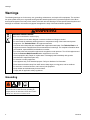
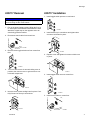
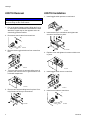
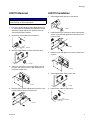
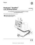
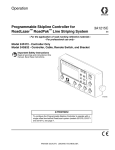
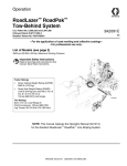
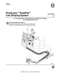
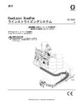
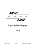
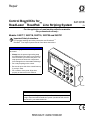
Repair
Control Board Kits for
3A1301B
™
™
EN
RoadLazer RoadPak Line Striping System
- For the application of road marking reflective materials - For professional use only -
Models: 24G717, 24G718, 24G719, 24G720 and 24G721
Important Safety Instructions
For complete warnings and safety instructions see RoadLazer™
RoadPak™ Line Striper System manual. Save these instructions.
NOTICE
To avoid damaging the electronic components of
the control:
•
•
•
•
Always use the personal grounding strap
provided with the kits when you remove the
cover and while you remove the parts. This
strap protects the electronic components
from damage due to electrostatic discharge.
A
B
C
D
E
F
SY
S
DE TEM
LA
Y
Do not lay anything on the control.
Be sure the open side of the control faces up
if you lay it down.
Do not twist or force parts. Align them
properly as instructed in this manual.
PO
W
ONER
ST
A
SK RT
SP IP
AC
E
BE
AD
SO
N
ME
NU
ME
NU
BE
AD
TE
ST
OF
F
P
SKROG
IPL RA
INE MM
CO ABL
NT E
RO
L
RE
SE
T
HO
LD
ti16358a
ATTENTION!
To configure the Programmable Skipline Controller to operate with a
single wheel tow-behind RoadLazer system (models 231378, 231571
and 231571), see manual 3A1215.
Warnings
Warnings
The following warnings are for the setup, use, grounding, maintenance, and repair of this equipment. The exclamation point symbol alerts you to a general warning and the hazard symbols refer to procedure-specific risks. When
these symbols appear in the body of this manual, refer back to these Warnings. Product-specific hazard symbols and
warnings not covered in this section may appear throughout the body of this manual where applicable.
WARNING
WARNING
EQUIPMENT MISUSE HAZARD
Misuse can cause death or serious injury.
• Do not operate the unit when fatigued or under the influence of drugs or alcohol.
• Do not exceed the maximum working pressure or temperature rating of the lowest rated system
component. See Technical Data in all equipment manuals.
• Use fluids and solvents that are compatible with equipment wetted parts. See Technical Data in all
equipment manuals. Read fluid and solvent manufacturer’s warnings. For complete information about
your material, request MSDS from distributor or retailer.
• Do not leave the work area while equipment is energized or under pressure. Turn off all equipment and
follow the Pressure Relief Procedure when equipment is not in use.
• Check equipment daily. Repair or replace worn or damaged parts immediately with genuine
manufacturer’s replacement parts only.
• Do not alter or modify equipment.
• Use equipment only for its intended purpose. Call your distributor for information.
• Route hoses and cables away from traffic areas, sharp edges, moving parts, and hot surfaces.
• Do not kink or over bend hoses or use hoses to pull equipment.
• Keep children and animals away from work area.
• Comply with all applicable safety regulations.
Grounding
The equipment must be grounded. Grounding
reduces the risk of static shock by providing an
escape path for the electrical current due to static
build up or in the event of a short circuit.
2
3A1301B
Warnings
24G717 Removal
24G717 Installation
1. Install toggle switch spacers on new board.
NOTICE
Wear the grounding strap provided with this kit to
avoid shorting out the circuit boards.
1. Put on the ground strap provided. Wrap the first 12
in. around your wrist with the black adhesive inward.
Attach the copper tape on the opposite end to an
electrically grounded surface.
2. Disconnect control cable from control box.
ti17054a
2. Install board on pin connections and tighten three
screws to hold board in place.
ti17049a
3. Remove three toggle switch nuts from control box
face.
BE
BE
AD
AD
RE
SO
TE
SE
HO
ti17052a
3. Replace cover and tighten six screws to hold cover
in place.
N
ST
T
LD
ti17050a
4. Turn over and remove six screws holding cover in
position, then remove cover to gain access to control board components.
ti17051a
4. Install toggle switch nuts into control box.
N
SO
AD
BE
ST
TE
AD
BE
ti17051a
5. Remove three screws holding board in place. Carefully lift board off from pin connections.
T
SE
RE
LD
HO
ti17050a
5. Install control cable on control box.
ti17052a
3A1301B
ti17049a
3
Warnings
24G718 Removal
24G718 Installation
1. Install toggle switch spacers on new board.
NOTICE
Wear the grounding strap provided with this kit to
avoid shorting out the circuit boards.
1. Put on the ground strap provided. Wrap the first 12
in. around your wrist with the black adhesive inward.
Attach the copper tape on the opposite end to an
electrically grounded surface.
2. Disconnect control cable from control box.
ti17055a
2. Install board on pin connections and tighten two
screws to hold board in place.
ti17049a
3. Remove three toggle switch nuts from control box
face.
E
ST
SY AY
DEL
T
D
A
BE
F
MEN
E
D
MEN
ti17056a
3. Replace cover and tighten six screws to hold cover
in place.
U
U
T
SE
RE
LD
HO
E
BL L
O
TR
ti17057a
ti17051a
4. Turn over and remove six screws holding cover in
position, then remove cover to gain access to control board components.
4. Install toggle switch nuts to control box.
E
ST
SY AY
DEL
T
AD
BE
F
MEN
E
D
MEN
U
U
T
SE
RE
LD
HO
ti17051a
5. Remove two screws holding board in place. Carefully lift board off from pin connections.
ti17056a
4
E
BL L
O
TR
ti17057a
5. Install control cable to control box.
ti17049a
3A1301B
Warnings
24G719 Removal
24G719 Installation
1. Install toggle switch spacer on new board.
NOTICE
Wear the grounding strap provided with this kit to
avoid shorting out the circuit boards.
1. Put on the ground strap provided. Wrap the first 12
in. around your wrist with the black adhesive inward.
Attach the copper tape on the opposite end to an
electrically grounded surface.
2. Disconnect control cable from control box.
ti17060a
2. Install board on pin connections and position board
spacer (S). Install and tighten three screws to hold
board in place.
S
ti17058a
ti17049a
3. Remove toggle switch nut from control box face.
R
WE
PO N
O
F
OF
3. Replace cover and tighten six screws to hold cover
in place.
LE
AB OL
MM TR
RA ON
OG E C
PR LIN
IP
SK
ti17059a
4. Turn over and remove six screws holding cover in
position, then remove cover to gain access to control board components.
ti17051a
4. Install toggle switch nut to control box.
R
WE
PO N
O
OF
ti17051a
5. Remove three screws holding board in place. Carefully lift board off from pin connections.
F
LE
AB O L
M M TR
RA ON
OG E C
P R LIN
IP
SK
ti17059a
5. Install control cable to control box.
ti17049a
ti17058a
3A1301B
5
Warnings
24G720 Removal
24G720 Installation
1. Place control board onto connecting membrane on
front of housing.
NOTICE
Wear the grounding strap provided with this kit to
avoid shorting out the circuit boards.
1. Put on the ground strap provided. Wrap the first 12
in. around your wrist with the black adhesive inward.
Attach the copper tape on the opposite end to an
electrically grounded surface.
ti17063a
2. Disconnect control cable from control box.
2. Install and tighten four screws to hold board into
place. Install and tighten side jack nut.
ti17049a
3. Turn over and remove six screws holding cover in
position, then remove cover to gain access to control board components.
ti17061a
3. Replace boards 24G719, 24G718, and 24G717 as
described earlier.
4. Replace cover and tighten six screws to hold cover
into position.
ti17051a
4. Remove boards 24G717, 24G718, and 24G719 as
described earlier.
5. Remove four screws holding board in place and
remove side jack nut.
ti17051a
5. Install control cable into control box.
ti17061a
6. Carefully remove board from connecting membrane
on front of housing.
ti17049a
ti17062a
6
3A1301B
Warnings
24G721 Removal
24G721 Installation
1. Replace housing.
NOTICE
Wear the grounding strap provided with this kit to
avoid shorting out the circuit boards.
N
SO
AD
BE
EM
ST
SY LAY
DE
AD
BE
ST
TE
F
1. Put on the ground strap provided. Wrap the first 12
in. around your wrist with the black adhesive inward.
Attach the copper tape on the opposite end to an
electrically grounded surface.
2. Disconnect control cable from control box.
T
AR
ST IP
SK E
AC
SP
U
MEN
E
D
U
MEN
C
B
T
SE
RE
A
LD
HO
ti17064a
R
WE
PO N
O
F
OF
LE
AB OL
MM TR
RA ON
OG E C
PR LIN
IP
SK
2. Replace boards 24G720, 24G719, 24G718, and
24G717 as described earlier.
ti17049a
3. Remove all toggle switch nuts from control box face.
3. Replace cover and tighten six screws to hold cover
into position.
4. Turn over and remove six screws holding cover in
position, then remove cover to gain access to control board components.
ti17051a
4. Install control cable to control box.
ti17051a
5. Remove boards 24G717, 24G718, 24G719, and
24G720 as described earlier.
ti17049a
3A1301B
7
Graco Standard Warranty
Graco warrants all equipment referenced in this document which is manufactured by Graco and bearing its name to be free from defects in
material and workmanship on the date of sale to the original purchaser for use. With the exception of any special, extended, or limited warranty
published by Graco, Graco will, for a period of twelve months from the date of sale, repair or replace any part of the equipment determined by
Graco to be defective. This warranty applies only when the equipment is installed, operated and maintained in accordance with Graco’s written
recommendations.
This warranty does not cover, and Graco shall not be liable for general wear and tear, or any malfunction, damage or wear caused by faulty
installation, misapplication, abrasion, corrosion, inadequate or improper maintenance, negligence, accident, tampering, or substitution of
non-Graco component parts. Nor shall Graco be liable for malfunction, damage or wear caused by the incompatibility of Graco equipment with
structures, accessories, equipment or materials not supplied by Graco, or the improper design, manufacture, installation, operation or
maintenance of structures, accessories, equipment or materials not supplied by Graco.
This warranty is conditioned upon the prepaid return of the equipment claimed to be defective to an authorized Graco distributor for verification of
the claimed defect. If the claimed defect is verified, Graco will repair or replace free of charge any defective parts. The equipment will be returned
to the original purchaser transportation prepaid. If inspection of the equipment does not disclose any defect in material or workmanship, repairs
will be made at a reasonable charge, which charges may include the costs of parts, labor, and transportation.
THIS WARRANTY IS EXCLUSIVE, AND IS IN LIEU OF ANY OTHER WARRANTIES, EXPRESS OR IMPLIED, INCLUDING BUT NOT LIMITED
TO WARRANTY OF MERCHANTABILITY OR WARRANTY OF FITNESS FOR A PARTICULAR PURPOSE.
Graco’s sole obligation and buyer’s sole remedy for any breach of warranty shall be as set forth above. The buyer agrees that no other remedy
(including, but not limited to, incidental or consequential damages for lost profits, lost sales, injury to person or property, or any other incidental or
consequential loss) shall be available. Any action for breach of warranty must be brought within two (2) years of the date of sale.
GRACO MAKES NO WARRANTY, AND DISCLAIMS ALL IMPLIED WARRANTIES OF MERCHANTABILITY AND FITNESS FOR A
PARTICULAR PURPOSE, IN CONNECTION WITH ACCESSORIES, EQUIPMENT, MATERIALS OR COMPONENTS SOLD BUT NOT
MANUFACTURED BY GRACO. These items sold, but not manufactured by Graco (such as electric motors, switches, hose, etc.), are subject to
the warranty, if any, of their manufacturer. Graco will provide purchaser with reasonable assistance in making any claim for breach of these
warranties.
In no event will Graco be liable for indirect, incidental, special or consequential damages resulting from Graco supplying equipment hereunder, or
the furnishing, performance, or use of any products or other goods sold hereto, whether due to a breach of contract, breach of warranty, the
negligence of Graco, or otherwise.
FOR GRACO CANADA CUSTOMERS
The Parties acknowledge that they have required that the present document, as well as all documents, notices and legal proceedings entered into,
given or instituted pursuant hereto or relating directly or indirectly hereto, be drawn up in English. Les parties reconnaissent avoir convenu que la
rédaction du présente document sera en Anglais, ainsi que tous documents, avis et procédures judiciaires exécutés, donnés ou intentés, à la suite
de ou en rapport, directement ou indirectement, avec les procédures concernées.
Graco Information
For the latest information about Graco products, visit www.graco.com.
TO PLACE AN ORDER, contact your Graco distributor or call 1-800-690-2894 to identify the nearest distributor.
All written and visual data contained in this document reflects the latest product information available at the time of publication.
Graco reserves the right to make changes at any time without notice.
For patent information, see www.graco.com/patents.
Original instructions. This manual contains English. MM 3A1301
Graco Headquarters: Minneapolis
International Offices: Belgium, China, Japan, Korea
GRACO INC. AND SUBSIDIARIES P.O. BOX 1441 MINNEAPOLIS, MN 55440-1441 USA
Copyright 2010, Graco Inc. All Graco manufacturing locations are registered to ISO 9001
www.graco.com
Revised - June 2013