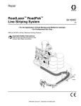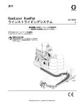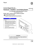
1
Operation
RoadLazer™ RoadPak™
Tow-Behind System
U.S. Patent No. 5,368,232 and 5,947,385
Chinese Patent ZL97111289.4
Brazilian Patent No. PI9701899-6
3A2091C
EN
- For the application of road marking and reflective coatings - For professional use only -
List of Models (see page 2)
2900 psi (20 MPa, 200 bar) Maximum Working Pressure
Important Safety Instructions
Read all warnings and instructions in this
manual. Save these instructions.
Trailer Ratings
•
Gross Vehicle Weight Rating (GVWR)
2800 lb (1270 kg)
•
Gross Axle Weight Rating (GAWR)
1200 lb (544 kg) per axle with 5.70 x 8
tire, 8 x 3.75 5-45 rim at
100 psi (690 KPA) cold single.
Tire Ratings
Size: 5.70 x 8, Load Range D
Cold tire pressure: 100 psi (690 KPA)
Lug Torque: 90-120 ft-lb (122-163 N•m)
NOTE: This manual replaces the Operation Manual (3A1214)
for the standard RoadLazer™ RoadPak™ Line Striping System.
ti18134a
Table of Contents
Table of Contents
Models . . . . . . . . . . . . . . . . . . . . . . . . . . . . . . . . . . . 3
Complete Assemblies . . . . . . . . . . . . . . . . . . . . . 3
Warnings . . . . . . . . . . . . . . . . . . . . . . . . . . . . . . . . . 4
Introduction and General Information . . . . . . . . . . 7
Introduction . . . . . . . . . . . . . . . . . . . . . . . . . . . . . 7
General Information . . . . . . . . . . . . . . . . . . . . . . 7
Component Identification . . . . . . . . . . . . . . . . . . . . 8
Component Function . . . . . . . . . . . . . . . . . . . . . . . 9
Pre-Setup Requirements . . . . . . . . . . . . . . . . . . . . 10
Tow Vehicle Requirements . . . . . . . . . . . . . . . . 10
Hitch Requirements . . . . . . . . . . . . . . . . . . . . . 10
Receivers . . . . . . . . . . . . . . . . . . . . . . . . . . . . . 10
Paint Drum Bracket . . . . . . . . . . . . . . . . . . . . . . 10
Programmable Skipline Controller . . . . . . . . . . 10
Hitch Receiver Kit: 238944 (Standard) . . . . . . . . . 11
Installation Instructions for Hitch Kit 238944 (straight
cross tube) . . . . . . . . . . . . . . . . . . . . . . . . . 11
Hitch Receiver Kit: 239692 (Optional) . . . . . . . . . 12
Installation Instructions for Hitch Kit 239692 (angled
cross tube) . . . . . . . . . . . . . . . . . . . . . . . . . 12
Setup . . . . . . . . . . . . . . . . . . . . . . . . . . . . . . . . . . . . 13
Charge Battery . . . . . . . . . . . . . . . . . . . . . . . . . 13
Grounding Instructions . . . . . . . . . . . . . . . . . . . 13
Level Draw Bar with Tow-Behind System . . . . . 13
Connect Tow-Behind to Vehicle . . . . . . . . . . . . 13
Trailer Tires . . . . . . . . . . . . . . . . . . . . . . . . . . . . 14
Gun Arm Beam Bracket . . . . . . . . . . . . . . . . . . 15
Gun Arm Stow Bracket . . . . . . . . . . . . . . . . . . . 15
Installing RoadLazer onto Trailer . . . . . . . . . . . 16
Adjustable Gun Arm Beam Installation (24G630) 16
Adjustable Gun Arm Installation (24G628, 24G629)
17
Install Safety Switch and Gun Arm Stow Plate . 17
Hose Routing to Pumps and Tanks . . . . . . . . . 20
Filter Orientation . . . . . . . . . . . . . . . . . . . . . . . . 21
Hose Routing . . . . . . . . . . . . . . . . . . . . . . . . . . 21
. . . . . . . . . . . . . . . . . . . . . . . . . . . . . . . . . . . . . 23
Notes . . . . . . . . . . . . . . . . . . . . . . . . . . . . . . . . . 24
Wiring Diagrams . . . . . . . . . . . . . . . . . . . . . . . . 25
Schematics - 24F472, Controller . . . . . . . . . . . 25
Schematics -16G161, Cable, Gun Arm . . . . . . . 26
Schematics - 16G049, Valve Air Solenoid . . . . 27
Install Simple Guide System . . . . . . . . . . . . . . . 28
2
Operation . . . . . . . . . . . . . . . . . . . . . . . . . . . . . . . . 29
Pressure Relief Procedure . . . . . . . . . . . . . . . . 29
Emergency Shut Off . . . . . . . . . . . . . . . . . . . . . 30
Load Reflecting Materials . . . . . . . . . . . . . . . . . 30
Set Up Adjustable Gun Arm Beam and Gun Arm 30
Prepare System to Paint . . . . . . . . . . . . . . . . . . 31
Start Engine . . . . . . . . . . . . . . . . . . . . . . . . . . . . 33
Select/Prime Pumps . . . . . . . . . . . . . . . . . . . . . 33
Prime Guns . . . . . . . . . . . . . . . . . . . . . . . . . . . . 34
Turn on Bead System . . . . . . . . . . . . . . . . . . . . 34
Begin to Spray . . . . . . . . . . . . . . . . . . . . . . . . . . 34
Flushing the System . . . . . . . . . . . . . . . . . . . . . 35
Securing Gun Arm for Transportation . . . . . . . . 37
Removing RoadLazer from Vehicle . . . . . . . . . . . 38
Repair . . . . . . . . . . . . . . . . . . . . . . . . . . . . . . . . . . . 39
Trailer Tire . . . . . . . . . . . . . . . . . . . . . . . . . . . . . 39
Trailer Tire Replacement . . . . . . . . . . . . . . . . . . 39
General Trailer Service . . . . . . . . . . . . . . . . . . . 39
Parts . . . . . . . . . . . . . . . . . . . . . . . . . . . . . . . . . . . . 40
Parts List . . . . . . . . . . . . . . . . . . . . . . . . . . . . . . 40
Parts . . . . . . . . . . . . . . . . . . . . . . . . . . . . . . . . . 41
Parts List . . . . . . . . . . . . . . . . . . . . . . . . . . . . . . 41
Technical Data . . . . . . . . . . . . . . . . . . . . . . . . . . . . 42
Notes . . . . . . . . . . . . . . . . . . . . . . . . . . . . . . . . . . . . 43
Graco Standard Warranty . . . . . . . . . . . . . . . . . . . 44
3A2091C
Models
Models
Ref.
Model Number
Description
1
24G624
1 Pump RoadPak
2
24G625
2 Pump RoadPak
3
24G628
1 Pump RoadPak Gun Arm
4
24G629
2 Pump RoadPak Gun Arm
5
24G630
Adjustable Gun Arm Beam
6
24G632
Programmable Skipline Controller
7
24G633
RoadView™ Camera System
8
24G634
Simple Guide System
9
24M255
Siphon and Drain Hose Extension Kit (Waterborne)
10
16M239
RoadPak Trailer (mounting parts not included)
11
239692
Hitch Receiver Kit (class 4, 2 in.)
12
24M138
Trailer Mounting Parts
Complete Assemblies
Part Number
Description
24M143
1 Pump Tow-Behind RoadPak System (1, 3, 5, 6, 8, 9, 10, 11, 12)
24M144
2 Pump Tow-Behind RoadPak System (2, 4, 5, 6, 8, 9 (x2), 10, 11, 12)
24M200
Tow-Behind Trailer Conversion Kit (9 (x2), 10, 11, 12)
16N437
1 Pump Tow-Behind System with Camera (1, 3, 5, 6, 7, 8, 9, 10, 11, 12)
16N438
2 Pump Tow-Behind System with Camera (2, 4, 5, 6, 7, 8, 9 (x2), 10, 11, 12)
3A2091C
3
Warnings
Warnings
The following warnings are for the setup, use, grounding, maintenance, and repair of this equipment. The exclamation point symbol alerts you to a general warning and the hazard symbols refer to procedure-specific risks. When
these symbols appear in the body of this manual, refer back to these Warnings. Product-specific hazard symbols and
warnings not covered in this section may appear throughout the body of this manual where applicable.
WARNING
WARNING
TOWING HAZARD
The driver can lose control when pulling trailer if correct equipment is not used. The driver and passengers could
be seriously injured. The vehicle or system may also be damaged.
• Tow vehicle must meet all requirements and load ratings. See Tow Vehicle Requirements.
• Clamp-on hitch receivers must be installed properly. See Tow Hitch Requirements.
• Do not use additional bead or paint tanks on Tow-Behind System.
• Clamp on hitch receivers are to be used for towing Graco double-hitch equipment only. Do not tow any
other equipment with these receivers.
• Do not use Tow-Behind System trailer for other equipment.
FIRE AND EXPLOSION HAZARD
Flammable fumes, such as solvent and paint fumes, in work area can ignite or explode. To help prevent fire
and explosion:
• Use equipment only in well ventilated area.
• Do not fill fuel tank while engine is running or hot; shut off engine and let it cool. Fuel is flammable and can
ignite or explode if spilled on hot surface.
• Eliminate all ignition sources; such as pilot lights, cigarettes, portable electric lamps, and plastic drop cloths
(potential static arc).
• Keep work area free of debris, including solvent, rags and gasoline.
• Do not plug or unplug power cords, or turn power or light switches on or off when flammable fumes are
present.
• Ground all equipment in the work area. See Grounding instructions.
• Use only grounded hoses.
• Hold gun firmly to side of grounded pail when triggering into pail.
• If there is static sparking or you feel a shock, stop operation immediately. Do not use equipment until you
identify and correct the problem.
• Keep a working fire extinguisher in the work area.
4
3A2091C
Warnings
WARNING
WARNING
SKIN INJECTION HAZARD
High-pressure fluid from dispensing device, hose leaks, or ruptured components will pierce skin. This may look
like just a cut, but it is a serious injury that can result in amputation. Get immediate SURGICAL TREATMENT.
• Keep clear of fluid outlet and leaks.
• Use guns, hoses and other components with pressure ratings equal to or higher than the pump rating.
+
• Follow the Pressure Relief Procedure before servicing or cleaning.
• Do not point dispensing device at anyone or at any part of the body.
• Do not stop or deflect leaks with your hand, body, glove, or rag.
• Tighten all fluid connections before operating the equipment.
• Check hoses and couplings daily. Replace worn or damaged parts immediately.
MOVING PARTS HAZARD
Moving parts can pinch, cut or amputate fingers and other body parts.
• Keep clear of moving parts.
• Do not operate equipment with protective guards or covers removed.
• Do not wear loose clothing, jewelry or long hair while operating equipment.
• Pressurized equipment can start without warning. Before checking, moving, or servicing equipment, follow
the Pressure Relief Procedure and disconnect all power sources.
EQUIPMENT MISUSE HAZARD
Misuse can cause death or serious injury.
• Do not operate the unit when fatigued or under the influence of drugs or alcohol.
• Do not exceed the maximum working pressure or temperature rating of the lowest rated system component.
See Technical Data in all equipment manuals.
• Use fluids and solvents that are compatible with equipment wetted parts. See Technical Data in all
equipment manuals. Read fluid and solvent manufacturer’s warnings. For complete information about your
material, request MSDS from distributor or retailer.
• Do not leave the work area while equipment is energized or under pressure. Turn off all equipment and
follow the Pressure Relief Procedure when equipment is not in use.
• Check equipment daily. Repair or replace worn or damaged parts immediately with genuine manufacturer’s
replacement parts only.
• Do not alter or modify equipment.
• Use equipment only for its intended purpose. Call your distributor for information.
• Route hoses and cables away from traffic areas, sharp edges, moving parts, and hot surfaces.
• Do not kink or over bend hoses or use hoses to pull equipment.
• Keep children and animals away from work area.
• Comply with all applicable safety regulations.
3A2091C
5
Warnings
WARNING
WARNING
CARBON MONOXIDE HAZARD
Exhaust contains poisonous carbon monoxide, which is colorless and odorless. Breathing carbon monoxide
can cause death.
• Do not operate in an enclosed area.
TOXIC FLUID OR FUMES HAZARD
Toxic fluids or fumes can cause serious injury or death if splashed in the eyes or on skin, inhaled, or swallowed.
• Read MSDSs to know the specific hazards of the fluids you are using.
• Store hazardous fluid in approved containers, and dispose of it according to applicable guidelines.
BURN HAZARD
Equipment surfaces and fluid that’s heated can become very hot during operation. To avoid severe burns:
• Do not touch hot fluid or equipment.
PERSONAL PROTECTIVE EQUIPMENT
Wear appropriate protective equipment when in the work area to help prevent serious injury, including eye
injury, hearing loss, inhalation of toxic fumes and burns. This equipment includes but is not limited to:
• Protective eyewear, and hearing protection.
• Respirators, protective clothing, and gloves as recommended by the fluid and solvent manufacturer.
CALIFORNIA PROPOSITION 65
The engine exhaust from this product contains a chemical known to the State of California to cause
cancer, birth defects or other reproductive harm.
6
3A2091C
Introduction and General Information
Introduction and General Information
Introduction
Simple Guide System
This manual and those supplied provide pre-setup
requirements, parts lists, setup, operation, and maintenance instructions for the RoadLazer RoadPak
Tow-Behind System. This manual includes instructions
for a 2-pump system. For 1-pump systems, all parts
remain the same with the exception of plugged ports for
missing pumps and hoses.
The Simple Guide System provides the user with a
pointer for alignment on either the left or right side of the
vehicle.
General Information
The Tow-Behind System is attached to a vehicle and is
used to apply up to two stripes in one or two colors with
glass beading.
RoadView™ Camera System (optional)
The RoadView Camera System provides the user with
video of a bore sight view for alignment on either the left
or right side of the tow vehicle. The system consists of a
9 in. monitor, interfacing cables, video camera and
mounting bracket.
RPS 2900 Hydraulic Pumps
The Tow-Behind System consists of a Programmable
Skipline Controller, Displacement Pumps, two Paint
Spray Guns, and two Bead Spray Guns.
The RPS 2900 Hydraulic Pump supplies paint to the
spray guns. There are two displacement pumps. Two
displacement pumps allows the user to have a two-color
system.
Programmable Skipline Controller
Paint Spray Guns
The Programmable Skipline Controller consists of the
control box and a 30 ft (9.1 m) cable. It is the main control for the Tow-Behind System and turns the spray guns
and accessories on and off.
The Paint Spray Guns are pneumatically triggered to
spray paint stripes when commanded by the Programmable Skipline Controller.
Bead Spray Guns
The Bead Spray Guns are pneumatically triggered to
spray reflective materials when commanded by the
Programmable Skipline Controller.
3A2091C
7
Component Identification
Component Identification
B
A
AC
Y
W
C
AK
T
AL
D
S
R
AB
E
F
P
G
H
M
N
J
K
L
AN
AJ
AR
AM
AP
ti18135a
AE
AD
AG
8
AF
3A2091C
Component Function
Component Function
A
Air Regulator
Allows regulation of the bead tank air pressure
B
Bead Tank
Holds up to 36 gallons (136 liters) of reflective materials or element for single or
double drop beading
C
Air Accumulator Tank
Helps reduce air temperature from compressor
D
Hydraulic Valve
Valve to shut off/on the hydraulic fluid to the hydraulic motor
E
Fluid Filter
Filters fluid between the fluid source and the spray gun
F
Pressure Drain Valve
Relieves fluid pressure when open
G
RPS 2900 Hydraulic Pump
Provides fluid to be sprayed through the spray gun
H
Fluid Outlet
Supplies fluid from the displacement pump to the spray gun
J
Fluid Inlet
Displacement Pump entry for fluid from the paint drums (paint drums not shown)
K
Electrical Junction Box
Allows the user access to electrical system
L
18 HP Engine
Powers the hydraulic pump and the air compressor
M
Battery
Provides power to start the engine and control box
N
Fuel Tank
Holds 6 gallons (23 liters) of gasoline
P
Hydraulic Pressure Control Knob
Provides adjustment of hydraulic pressure (clockwise increases pressure)
R
Compressor
Provides an air supply for the solenoids and pressurizes the bead tanks
S
Hydraulic Reservoir
Holds 4 gallons (15.1 liters) of hydraulic oil for the hydraulic pump
T
I/O Cable
Carries electronic control signals from the controller to the RoadLazer
W
Programmable Skipline Controller
Allows the user to program the operation of the RoadLazer
Y
Air Pressure Quick Connect
Allows the user to use pressurized air
AB
Stow Bracket Pin
Secures the spray gun boom arm when the RoadLazer is in transport mode
AC
Breather Cap
Provides a means for hydraulic reservoir ventilation, oil check, and fill
AD
Adjustable Gun Arm Beam
Supports the RoadPak Gun Arm
AE
RoadPak Gun Arm
Allows striping on either side of the vehicle at adjustable distances
AF
Bead Spray Gun
Sprays beads when commanded by the Controller
AG
Paint Spray Gun
Sprays fluid when controller by the Controller
AJ
Simple Guide System
Provides an alignment tool for the user
AK
Gun Arm Stow Bracket
Allows upright storage of RoadPak gun arm
AL
Gun Arm Stow Plate
Allows connection between stow bracket and spray gun boom arm
AM
Trailer Jack
Used to hold Tow-Behind System upright when disconnected from tow vehicle
and during storage
AN
Gun Arm Beam Bracket
Supports the slide beam
AP
Wheel Assembly
Supports RoadLazer RoadPak trailer
AR
RoadLazer RoadPak Trailer
Allows user to tow RoadPak behind a vehicle
3A2091C
9
Pre-Setup Requirements
Pre-Setup Requirements
Tow Vehicle Requirements
Receivers
•
Tow vehicle with minimum wheel base (front to back)
of 130 in (330 cm).
•
Tow vehicle with minimum rated payload capacity of
3500 lb (1588 kg). NOTE: Tongue weight (TW) of
Tow-Behind System is 1000 lb (454 kg).
Two Graco clamp-on receivers must be mounted 36 in.
(91 cm) on center on the installed DRAW-TITE Class IV
Ultra Frame Hitch. See Hitch Receiver Kit for mounting
instructions, pages 11 and 12.
•
Tow vehicle with minimum rated capacity of 7500 lb
(3402 kg) gross trailer weight (GTW)
•
Tow hitch with minimum rated capacity of 750 lb
(340 kg) TW, 7500 lb (3402 kg) GTW.
•
Warning lights and/or sign board per federal, state,
and local regulations. Reference Part IV of the
Manual on Uniform Traffic Control Devices (MUTCD)
by the U.S. Department of Transportation, Federal
Highway Administration, or equivalent regulations for
your region.
•
Securing device for paint supply containers.
•
Standard trailer light connector.
•
I/O cable access from the tow vehicle cab to the
RoadLazer.
Hitch Requirements
Have a DRAW-TITE® Class IV Ultra-Frame tow hitch (or
equivalent hitch with a 7500 lb (3402 kg) GTW rating and
3 in. x 3 in. (7.6 cm x 7.6 cm) square cross tube) installed
on your vehicle (reference DRAW-TITE part no. series
419XXX). NOTE: Tow hitch not supplied by Graco.
Paint Drum Bracket
Paint drums are heavy and could shift from side to side
when the tow vehicle is cornering. The paint drums
could fall from the vehicle and cause serious injury.
Secure the drums when the vehicle is moving.
It is recommended that the paint drums be secured with a
paint drum bracket. Graco does not provide a paint drum
bracket with the Tow-Behind System.
Programmable Skipline
Controller
The Programmable Skipline Controller must be installed
in the cab of the tow vehicle. Select a position for ease of
operation. This controller connects to the RoadPak with
an I/O cable, so there must be cable access from the tow
vehicle cab to the RoadPak. See manual 3A1215.
Choose a ball mount that allows the Tow-Behind System
to travel level to the ground with an average payload. A
recommended option is two DRAW-TITE adjustable 2 in.
(5 cm) ball mounts. The ball mount must have a 2 in. x 2
in. (5 cm x 5 cm) insert with at least a 1 in. diameter ball
mount hole. The ball mount hole and shank diameter
must match. The ball mount must have a rating of at least
5000 lb (2270 kg) GTW, 5000 lb (2270 kg) TW.
10
3A2091C
Hitch Receiver Kit: 238944 (Standard)
Hitch Receiver Kit: 238944 (Standard)
Installation Instructions for Hitch Kit 238944 (straight cross tube)
1
Torque to 220-240 ft-lb (298-325 N•m)
Ref.
1
2
DRAW-TITE® Class IV Ultra-Frame tow
hitch is not included. Cross tubes must be
3 in. x 3 in. (7.6 cm x 7.6 cm) square.
2
Part
Description
113665 SCREW, cap, hex head,
grade 8; 5/8-11 unc-2a;
4.5 in. (11.4 cm)
113980 NUT, lock, hex, grade 8;
5/8-11 unc-2b
Qty.
6
6
A
2
7246c
18 in.
36 in.
1 1
2
NOTE: For the nearest DRAW-TITE® installer call 1-800-428-7303
NOTE: Pre-torque each of the screws to set the
hitch receiver in place.
1. Have a DRAW-TITE® Class IV Ultra-Frame tow
hitch (or equivalent hitch with a 7500 lb (3401 kg)
GTW rating and 3 in. x 3 in. (7.6 cm x 7.6 cm)
square cross tube) installed on your vehicle (reference DRAW-TITE® part no. series 419XXX).
4. Repeating the process from step 2, attach the right
hitch receiver (4) to the trailer hitch with the three
remaining screws (1) and nuts (2).
2. Both of the Graco clamp-on receivers must be 18 in.
from the center of the hitch frame (A).
5. Verify that the centers of the hitch receivers are 36
in. (91 cm) apart. Make any necessary adjustments.
3. Attach the left hitch receiver (3) to the trailer hitch
with three of the supplied screws (1) and nuts (2).
6. Torque all of the screws to 220-240 ft-lb (298-325
N•m).
3A2091C
11
Hitch Receiver Kit: 239692 (Optional)
Hitch Receiver Kit: 239692 (Optional)
Installation Instructions for Hitch Kit 239692 (angled cross tube)
1
Torque to 220-240ft-lb (298-325 N•m)
Ref.
1
2
DRAW-TITE® Class IV Ultra-Frame tow
hitch is not included. Cross tubes must be
3 in. x 3 in. (7.6 cm x 7.6 cm) square
2
A
Part
Description
113665 SCREW, cap, hex head,
grade 8; 5/8-11 unc-2a;
4.5 in. (11.4 cm)
113980 NUT, lock, hex, grade 8;
5/8-11 unc-2b
Qty.
6
6
2
1
1
18 in.
2
36 in.
7247c
NOTE: For the nearest DRAW-TITE® installer call 1-800-428-7303
4. Repeating the process from step 2, attach the right
hitch receiver (4) to the trailer hitch with the three
remaining screws (1) and nuts (2).
1. Have a DRAW-TITE® Class IV Ultra-Frame tow
hitch (or equivalent hitch with a 7500 lb (3401 kg)
GTW rating and 3 in. x 3 in. (7.6 cm x 7.6 cm)
square cross tube) installed on your vehicle (reference DRAW-TITE® part no. series 419XXX).
5. Verify that the centers of the hitch receivers are 36
in. apart. Make any necessary adjustments.
2. Both of the Graco clamp-on receivers must be 18 in.
from the center of the hitch frame (A).
6. Torque all of the screws to 220-240 ft-lb (298-325
N•m).
3. Attach the left hitch receiver (3) to the trailer hitch
with three of the supplied screws (1) and nuts (2).
NOTE: Pre-torque each of the screws to set the
hitch receiver in place.
12
3A2091C
Setup
Setup
Connect Tow-Behind to Vehicle
Charge Battery
If the battery is newly purchased or has not been used
for a long time, charge it before you use it.
If the wheels are not rotated to the rear of the trailer, it
can become unstable and tip over if the tow vehicle is
removed, causing serious injury.
Grounding Instructions
Only remove the Tow-Behind system from its tow
vehicle when the wheels are facing the rear of the
trailer and are blocked on both sides.
1. Attach Tow-Behind System ground clamp to earth
ground.
ti18281a
TI3058A
Level Draw Bar with Tow-Behind
System
Use the following procedure to ensure level operation of
the Tow-Behind System.
ti18279a
1. Empty tow vehicle of any payload.
2. Install draw bar to measure approximately 22 in. (56
cm) from top of ball mount to ground.
1. Install two ball mounts in hitch receivers:
a. Slide ball mount into hitch receiver.
6244a
22 in.
(56 cm)
ti18138a
NOTE: For initial setup, leave trailer on supplied pallet
until final step of Connect Tow-Behind System to
Vehicle procedure.
3A2091C
b. Insert pin.
c.
Insert clip.
13
Setup
2. Connect trailer to ball mounts:
a. Back tow vehicle into trailer and align ball
mounts with trailer arms.
g. Rotate jack to horizontal position. Insert safety
pins into place to secure jacks.
b. Crank trailer arm jacks to clear ball mounts.
ti18141a
3. Shorten each safety chain:
a. Unscrew nut fastening chain to RoadLazer.
ti18139a
c.
Move tow vehicle backward and align ball
mounts under trailer arms.
d. Crank trailer arm jacks to lower RoadPak trailer
arms onto ball mounts.
b. Refasten chain to RoadLazer so it connects to
tow vehicle with minimum slack.
4. Connect wires for lights.
5. If trailer is still attached to shipping pallet, remove
straps and tow trailer off of pallet.
Trailer Tires
Trailer tires can cause noticeable vibration when out of
balance. For extended highway use Graco recommends
adding 1 oz. of Dyna Beads® to each wheel. Dyna
Beads and installation instructions can be found at:
www.innovativebalancing.com.
ti18140a
e. Secure safety pins (A) for both trailer arm couplers and connect safety chains.
f.
Connect safety chains.
A
ti18142a
14
3A2091C
Setup
Gun Arm Beam Bracket
Gun Arm Stow Bracket
1. Center Gun Arm Beam Bracket on trailer
cross-member as shown and install supplied bolts
and nuts as shown. Torque to 215-235 in-lb
(24.3-26.5 N•m).
NOTE: Install Gun Arm Stow Bracket before mounting
RoadPak to trailer.
1. Align stow bracket with mounting holes.
2. Install and tighten four bolts and washers (use one
washer on each side of each bolt). Torque bolts to
28 ft-lb (38 N•m).
ti18145a
ti18136a
3A2091C
15
Setup
Installing RoadLazer onto Trailer
After loading the RoadPak on the trailer, secure the
RoadPak to the trailer using the supplied bolts, nuts,
and washers. Torque bolts to 28 ft-lb (38 N•m). Replace
rear jack.
If RoadPak is not properly secured to trailer, it can fall
off of trailer and cause serious injury.
Use only Graco supplied fasteners and tighten them to
the required torque. Use all of the fasteners provided.
NOTE: Only install RoadLazer onto trailer if trailer is
properly attached to tow vehicle.
NOTE: Remove rear jack from trailer before mounting
RoadPak.
NOTE: If tow vehicle is a pick-up, remove tailgate before
installation.
Load RoadPak onto trailer using a forklift or a hoist that
is rated for the weight of the RoadPak. For RoadPak
weight information see Technical Data, page 42.
ti18137a
Adjustable Gun Arm Beam
Installation (24G630)
The gun arm beam is shipped at 87.75 in. (2.2 m) long
to accommodate wider vehicles. The beam can be cut
down to 75.75 in. (1.9 m) long or 60 in. (1.5 m) long to
accommodate different vehicle sizes.
1. To shorten the beam to 75.75 in. (2.2 m), cut 12 in.
(30 cm) from the end of the beam towards the next
hole on the beam. To shorten the beam to 60 in.
(1.5 m), cut 27.75 in. (70 cm) from the end of the
beam towards the third hole as shown below.
27.75 in.
12 in.
ti18377a
ti16600a
2. After shortening to the desired length, slide the
beam into the channel in the gun arm beam bracket.
ti16665a
ti18144a
16
3A2091C
Setup
Adjustable Gun Arm Installation
(24G628, 24G629)
Install Safety Switch and Gun
Arm Stow Plate
1. Position the gun arm next to the vehicle.
2. Pull the gun arm beam out to the side of the vehicle
where the gun arm is located. Lift the gun arm and
hold the traverse bracket in the position shown
below. Slide the beam through the wheels so they
are mounted on the track of the gun arm beam as
shown below.
1. Remove two nuts and washers from safety switch
bracket and remove from gun arm.
ti18147a
2. Disconnect two wires on safety switch and pull wires
out of rectangular tube.
ti18143a
3. Attach the handle (704) to each end of the gun arm
beam. Press the cotter pin (707) through the handle
to hold it in place. Fasten nut (706) and bolt (705)
through the slide beam on both ends to act as stops
on the channel.
ti18147a
ti18147a
3. Reposition and install safety switch bracket as
shown.
708
707
704
706
ti16662a
705
ti18150a
4. Install gun arm stow plate as shown.
ti18147a
3A2091C
17
Setup
5. Hand-tighten two mounting nuts but allow enough
movement to make slight adjustments once in
place.
ti18148a
6. Connect safety switch wires.
ti18154a
ti18152a
NOTICE
Use cable ties to secure wires to gun arm. System will
not operate if wires become damaged.
8. Measure gap between safety switch and stowing
bracket. NOTE: If gap is less than 0 in. or greater
than 3/16 in. (4.7 mm) use a mallet to tap stowing
bracket to create a proper gap. Move safety switch
away from this area when adjusting gap.
7. Swing gun arm up and align stow plate in channel of
stow bracket. Slide gun arm towards center of stow
bracket until safety switch aligns with stow bracket
as shown. NOTE: Be sure that the hose bundle
does not become caught or pinched when moving
gun arm.
ti18158a
9. Align hole in stow bracket with slot in stow plate.
install safety pin.
18
3A2091C
Setup
ti18159a
ti18157a
10. Align safety switch bracket so safety switch is
aligned with stowing bracket as shown and tighten
nuts.
3A2091C
19
Setup
Hose Routing to Pumps and Tanks
ti18153a
20
3A2091C
Setup
Filter Orientation
1. Use a hammer to loosen the large jam nut on the
pump assembly.
1. Pull gun arm beam out to one side of the vehicle.
Pull gun arm out and lower it to make sure the hose
bundle has been secured at the proper location to
ensure full movement for the gun arm to move from
one side to the other. Make adjustments as needed.
ti16782a
ti18276a
2. Rotate the filter assembly to the desired orientation
and use a hammer to tighten the jam nut and lock
the assembly into place.
2. Lift gun arm back to the stow position. Pull gun arm
beam out to other side of vehicle and pull the gun
arm to that side to ensure the hose location is adequate for full movement.
ti16784a
ti16783a
Hose Routing
NOTICE
Never allow hoses to touch the ground during operation. Damage to hoses will occur. Attach a tie-down
strap across the truck bed and lay excess hose on top
of the strap to suspend excess hose length.
ti18277a
3. Put gun arm back to the stow position and pin it into
place. Center the gun arm beam to the vehicle. Lock
the gun arm beam and gun arm into place by
engaging the clamps for each.
ti18151a
NOTE: If tow vehicle is a pick-up, remove tailgate.
ti18156a
Underside View
3A2091C
21
Setup
Hose Connection
1. Modify suction hoses by loosening the hose clamps
and separating the flexible hose from the bent
siphon tube. Install barbed coupler and extension
hose as shown.
5. Install paint lines to RPS 2900 filter assemblies. For
a two color system, route the hose from paint gun 1
to pump 1 and route one hose from paint gun 2 to
pump 1. Route the second hose from paint gun 2 to
pump 2.
ti18278a
ti16446a
2. Use supplied clamps to secure suction hose to each
end of the barbed coupler and to bent siphon tube.
6. Install bead lines to the bead tank.
3. Install modified suction tubes on the RPS 2900
pump and route to paint drum.
ti16598a
ti16445a
ti16444a
7. Install air hose to quick connect fitting on air tank.
4. Extend return line by adding extra hose length and
fitting included in the siphon and drain hose extension kit. Install return line on the RPS 2900 filter
assembly and route back to the paint drum.
ti16914a
ti16597a
22
3A2091C
Setup
Electrical Cable Connections
1. Connect gun arm cable to the junction box. Fasten
cable to cable clamp for strain relief (S) on the connection.
ti16596a
S
3. Route the control cable to the cab of the vehicle
without pinching the cable. Connect the cable to the
Programmable Skipline Controller. Route cable
through the cable clamp for strain relief on the connection.
ti16601a
2. Connect control cable to the junction box. Fasten
cable to cable clamp for strain relief (S) on the connection.
ti16595a
3A2091C
S
23
Setup
Notes
24
3A2091C
Setup
Wiring Diagrams
Schematics - 24F472, Controller
Control Cable Diagram for RoadPak System
Contact
Description
Action
12 VDC
Leave Open- Do Not Connect
Leave Open- Do Not Connect
Sensor, pump (1)
Sensor, pump (2)
Paint Gun (1) Solenoid 1
Paint Gun (2) Solenoid 3
Paint Gun (3) Solenoid 5
Bead Gun (1) Solenoid 2
Bead Gun (2) Solenoid 4
Bead Gun (3) Solenoid 6
Engine Shutdown (ground)
Ground **
Ground **
Ground **
Sensor Distance
Ground **
Leave Open- Do Not Connect
Supply Voltage
Input
Input
Output (1 amp Max)
Output (1 amp Max)
Output (1 amp Max)
Output (1 amp Max)
Output (1 amp Max)
Output (1 amp Max)
A
B
C
D
E
F
SY
ST
DE EM
LA
Y
PO
W
ONER
ST
AR
SK T
SP IP
AC
E
BE
AD
SO
ME
N
NU
ME
NU
BE
AD
OFF
TE
ST
PR
SK OG
IPLI RAM
NE M
CO ABLE
NTR
OL
RES
ET
9
HO
LD
ti16358a
Input
Schematics - 24F922, BOARD,
Interconnect
24F469, Cable, Control
1
2
3
4
5
6
7
8
9
10
11
12
13
14
15
16
17
18
6
10
7
11
15
13
14
16
18
9
1
2
17
4
5
3
8
6
10
7
11
12
15
13
14
18
17
+12 VDC Postive Battery
4 AMP
20 AMP
3A2091C
5
3
8
16
Negative battery
Yellow +12 VDC Engine Auxiliary
White Engine Shutdown
1
2
3
4
2
4
12
24F922, BOARD,
Interconnect
PIN
1
Description
Not Used
Pump Counter Signal
Pump Counter Ground
Pumper Counter Power +12 VDC
ti17509b
PIN
Description
1
2
3
4
5
6
7
8
9
10
Paint Gun (1) Solenoid 1
Bead Gun (1) Solenoid 2
Paint Gun (2) Solenoid 3
Bead Gun (2) Solenoid 4
Paint Gun (3) Solenoid 5
Bead Gun (3) Solenoid 6
Wheel Sensor Signal
Wheel Sensor Ground
Wheel Sensor Power + 12 VDC
Solenoid Power + 12 VDC
1
2
3
4
5
6
7
8
9 10
25
Setup
Schematics -16G161, Cable, Gun Arm
16G161, Cable, Gun Arm
26
10
BLUE
8
6
ORANGE
6
5
WHITE/BLACK
5
4
RED/BLACK
4
3
WHITE
3
2
GREEN/BLACK
2
1
ORANGE/BLACK
1
9
RED
8
BLACK
7
GREEN
19418-0022 & 19420-0002
FEMALE TERMINALS
19418-0024 & 19420-0002
FEMALE TERMINALS
16G161, Cable, Gun Arm
3A2091C
Setup
Schematics - 16G049, Valve Air Solenoid
16G049, Valve, Air Solenoid
1
(Gun On)
2
3
4
5
6
PIN
1
2
3
Description
Wheel Sensor Power +12VDC
Wheel Sensor Ground
Wheel Sensor Signal
A
15E943, Senor Distance
B
(Gun Off)
3
16G049, Valve, Air Solenoid
F-1/4” QC.
19435-0814 & 19417-0028
MALE TERMINALS
F-1/4” QC.
1
2
3
8
RED (12vdc FROM BATTERY)
6
BLACK (GROUND SWITCHED AT CONTROLLER)
5
BLACK (GROUND SWITCHED AT CONTROLLER)
4
BLACK (GROUND SWITCHED AT CONTROLLER)
3
BLACK (GROUND SWITCHED AT CONTROLLER)
2
BLACK (GROUND SWITCHED AT CONTROLLER)
1
BLACK (GROUND SWITCHED AT CONTROLLER)
2
1
ARM-UP
SAFETY SWITCH
(
MAC VALVES
SOLENOID F BEAD 3
SOLENOID E BEAD 3
SOLENOID D BEAD 2
SOLENOID C BEAD 2
SOLENOID B BEAD 1
SOLENOID A BEAD 1
#1 RED (12vcd)
#2 BLACK (GRD)
#1 GREEN (SIGNAL +)
ti17511b
3A2091C
27
Setup
Install Simple Guide System
1. Locate an area on the vehicle to mount the Simple
Guide System that will allow the user to see the indicator rod from the driving position or with the help of
the RoadView Camera System.
5. Slide support bar (351) through brackets (355) and
tighten fasteners to secure in place.
355
351
ti17000a
6. Assemble extension clamp to support bar.
ti16408a
2. If needed, drill two 9/16 in. holes in the desired location.
3. Assemble mounting bracket (355) to desired location with bolt (359), washer (360), and nut (361).
361
ti16925a
7. Insert indicator rod (362) into guide extension arm
(352) and secure in place with knob(354).
8. Adjust the indicator rod by loosening extension
clamps and sliding the guide extension arm (352) to
desired position. Secure by tightening knob (354).
Install and Align RoadView Camera System
(Optional)
360
355
See RoadView Camera System manual.
359
ti16927a
4. Hand tighten lock bar (6) to mounting bracket (355)
with bolts (357) and nuts (358).
358
6
357
28
ti16926a
3A2091C
Operation
Operation
5. Close paint gun ball valves.
Pressure Relief Procedure
The system pressure must be manually relieved to prevent the system from starting or spraying accidentally.
Fluid under high pressure can be injected through the
skin and cause serious injury. To reduce the risk of an
injury from injection, splashing fluid, or moving parts,
follow the Pressure Relief Procedure whenever you:
•
are instructed to relieve the pressure
•
stop spraying
•
check or service any of the system equipment
•
install or clean the spray tip
ti15953a
6. Open all drain valves, one at a time.
7. Close valves immediately to prevent paint from drying in system. NOTE: If you suspect that the spray
gun or hose is completely clogged, or that pressure
has not been fully relieved after following the steps
above, very slowly loosen the hose end coupling,
and relieve pressure gradually. Then loosen it completely. Then clear the valve or hose.
RPS 2900 Pump Fluid Pressure Relief
Bead System Pressure Relief
1. Set hydraulic valve to OFF position.
1. Relieve air pressure in bead tank by turning bead
system valve to OFF position.
ti16550a
ti15838a
2. Run engine at half throttle.
Air System Pressure Relief
3. Place empty pail under paint guns to catch drainage.
1. Relieve air pressure in air tank by turning air valve
to OPEN position.
4. Relieve hose pressure through guns. Use Programmable Skipline Controller to trigger each gun for at
least 3 seconds each. NOTE: Always relieve pressure with the guns--not with the filter drain valves.
ti16961a
3A2091C
29
Operation
Emergency Shut Off
To shut down the entire Tow-Behind system, set
POWER ON/OFF on the Programmable Skipline Controller to the OFF position.
Set Up Adjustable Gun Arm
Beam and Gun Arm
1. Unlock gun arm clamp and gun arm beam clamps.
Load Reflecting Materials
1. Set POWER ON/OFF on Programmable Skipline
Controller to OFF.
2. Set RoadPak engine ignition key to OFF.
3. Relieve air system pressure by opening ball valve
until gauge reads 0.
4. Relieve air pressure in bead tank by turning bead
system valve to OFF position.
5. Remove cover from bead tank.
6. Screen reflective materials to prevent debris from
entering tank.
ti16425a
2. Pull gun arm beam to left or right side of vehicle.
Lock slide beam clamps.
3. Remove gun arm from upright stowed position, and
slide to end of gun arm beam. Slowly lower gun
arm, and lock into position with clamp.
7. Load bead tank with reflective materials.
ti16423a
30
3A2091C
Operation
Prepare System to Paint
6. Check oil level in compressor. NOTE: If red dot is
visible, add oil.
Initial Settings
1. Attach Tow-Behind System ground clamp to earth
ground. See Grounding Instructions, page 13.
2. Fill throat packing nut with TSL to prevent premature packing wear. Do this each time you spray and
store.
7. Verify all hose/fitting connections are tight.
8. Turn hydraulic lines to closed position.
Approximate
Fill Level
ti5240a
3. Check engine oil level. Add SAE 10W-30 (summer)
or 5W-20 (winter), if necessary.
ti15838a
9. Turn pump lever by guns 1/4 turn to OFF position.
(cold)
ti16447a
4. Fill fuel tank.
5. Check hydraulic oil level. Add only Graco Hydraulic
Oil, ISO 46 169236 (5 gallon/18.9 liter) or 207428 (1
gallon/3.8 liter). Hydraulic tank capacity is approximately 4.0 gallons (15.14 liters).
ti5243a
3A2091C
ti15953a
10. Place suction tube and drain tube in grounded metal
pail partially filled with flushing fluid. Attach ground
wire to pail and to earth ground.
Safe Range (cold)
31
Operation
ti16553a
ti16547a
13. Turn pressure control counterclockwise to lowest
pressure.
11. Turn prime valve down.
ti16552a
12. Install clean inlet strainer. NOTE: There must be a
minimum of 0.5 in. (1.3 cm) between bottom of
strainer and suction tube.
32
ti16919a
3A2091C
Operation
Start Engine
3. When flushing fluid comes out of return lines, set
hydraulic valve to OFF position.
1. Set POWER ON/OFF on Programmable Skipline
Controller to ON.
2. Set engine to choke position ON.
3. Set throttle to half speed and turn key.
ti15838a
4. Place suction hoses in paint drums.
4. After engine starts, set choke to OFF.
Select/Prime Pumps
ti16645a
1. Open hydraulic valves to activate pumps.
5. Open hydraulic valves to activate pumps.
ti16920a
ti16920a
2. Slowly turn pressure control clockwise until pump
begins to stroke.
6. When paint comes out of return lines, set hydraulic
valve to OFF position.
7. Close all prime valves.
ti16551a
ti16922a
3A2091C
8. Place return lines into paint drum.
33
Operation
Prime Guns
Turn on Bead System
1. Close air valve to pressurize air system.
1. Turn bead system valve to ON position.
ti16959a
2. Open only spray gun ball valves corresponding to
paint pumps or color used. NOTE: Never open both
ball valves on the two-color gun at the same time.
Paint color contamination could result.
ti16549a
2. Set desired bead tank pressure by turning regulator
knob.
ti15657a
3. Turn guns on with Programmable Skipline Controller (see Skipline Controller manual).
+
4. Place an empty pail under spray guns to catch
drainage from spray guns.
5. Set hydraulic valve(s) to ON position to activate
pumps.
ti16910a
3. Remove and secure ground clamp from earth
ground.
4. System is now ready for painting. Select guns 1 or 2
with the Programmable Skipline Controller.
ti16920a
6. When paint begins to flow out of guns, turn off guns
with Programmable Skipline Controller.
34
Begin to Spray
Select appropriate procedure from menu on RoadLazer
control system. See Skipline Controller manual.
3A2091C
Operation
Flushing the System
5. Place paint return lines in empty pail.
6. Open all paint pump dump valves.
When flushing system, always connect grounding cord
to reduce the risk of fire and explosion.
ti16552a
NOTE: Use only compatible solvents to flush system.
1. Perform Pressure Relief Procedure, see page 29.
2. Attach Tow-Behind System with grounding clamp to
earth ground. NOTE: The grounding clamp is
required for safe RoadPak operation. The grounding
clamp is for stationary use only.
3. Set pump hydraulic valves to OFF position.
7. Turn on Programmable Skipline Controller.
NOTE: Unit will not start until Controller is turned
ON.
8. Start Engine.
a. Set choke ON.
b. Set throttle to half speed.
c.
Turn key.
d. After engine starts, set choke to OFF.
e. Set throttle to desired speed.
ti15838a
4. Fill a grounded 5 gallon (19 liter) pail with flushing
fluid. Place paint suction hose in pail.
To reduce the risk of static sparking and splashing,
always remove the spray tip from the gun, and hold a
metal part of the gun firmly to the side of a grounded
metal pail during flushing.
9. Set hydraulic valve to ON position to activate
pumps.
ti16547a
ti16920a
10. When flushing fluid comes out of spray gun, set
hydraulic valve to OFF position.
3A2091C
35
Operation
16. When flushing fluid comes out of spray gun, set
hydraulic valve to OFF position.
11. Close dump valves.
17. Turn off guns with Programmable Skipline
Controller.
18. Shut off engine and Programmable Skipline Controller.
ti16551a
19. Leave paint pump dump valves and spray gun ball
valves open.
12. Open only spray gun ball valves corresponding to
paint pumps or color used. NOTE: Never open both
valves on the two-color gun at the same time. Paint
color contamination could result.
20. Remove and secure ground clamp from earth
ground.
13. Place empty pail under spray guns to catch
drainage from spray guns.
14. Turn guns on with Programmable Skipline
Controller.
15. Set hydraulic valves to ON position to activate
pumps.
ti16920a
36
3A2091C
Operation
Securing Gun Arm for
Transportation
4. Put stow bracket pin through gun arm stowing
bracket and plate. Secure with attached clip.
.
NOTICE
Never transport the RoadLazer while the paint gun ball
valves are open, the system is under pressure, and the
engine is running, as this could cause accidental discharge.
ti18157a
5. Unlock two red-handled clamps and center the gun
arm beam on the trailer.
1. Perform Pressure Relief Procedure, page 29.
2. Unlock gun arm red-handled clamp on gun arm
beam.
ti16923a
6. Lock three red-handle clamps to secure the slide
beam and gun arm.
ti16425a
3. Lift gun arm up from ground, and push in to center
of Tow-Behind System.
ti16915a
ti18154a
3A2091C
ti18280a
37
Removing RoadLazer from Vehicle
Removing RoadLazer
from Vehicle
A free-standing RoadLazer RoadPak Tow-Behind
System could become unstable when being moved
without a tow vehicle, causing serious injury.
To reduce the risk of injury and equipment damage,
never move Tow-Behind System without it being
properly secured to a tow vehicle.
If the wheels are not rotated to the back of the trailer,
it can become unstable and tip over if the tow vehicle
is removed.
Never remove the Tow-Behind RoadLazer RoadPak
from its tow vehicle if the wheels are not facing the
rear of the trailer.
1. Park on level concrete surface where Tow-Behind
System is intended to be parked.
NOTE: Make sure trailer wheels are at the far rear
of the trailer as shown. If parking the trailer with
wheels in this orientation is not possible, use rear
jack to lift tires and rotate wheels into their correct
orientation, then lower to ground.
2. Block trailer wheels.
3. Disconnect Programmable Skipline Controller,
trailer lighting, suction tubes, return lines, and any
straps that connect RoadLazer or its hose assemblies to the tow vehicle. Do not disconnect safety
chains.
4. Remove safety pins and rotate two side jacks and
rear jack to vertical position. Replace safety pins to
secure jacks.
5. Crank rear jack until jack foot plate touches the
ground. Crank jack 5 more times to help stabilize
trailer while in storage. Make sure wheels do not
leave the ground. If wheels leave the ground, lower
jacks until all trailer wheels are in contact with the
ground.
6. Unlatch ball couplers and crank side jacks to raise
trailer arms from ball mounts.
NOTE: Crank jacks sequentially (3 - 4 turns per
side) to ensure the trailer arms are lifted evenly,
keeping the trailer stable.
7. Disconnect safety chains.
8. Move tow vehicle forward to clear ball mounts. If all
connections between vehicle and trailer have been
removed, the tow vehicle can be removed from the
trailer.
9. Crank jacks down equally to bring Tow-Behind
System to level position for storage.
10. Always use rear jack during storage to provide additional stability.
ti18281a
ti18279a
38
3A2091C
Repair
Repair
Trailer Tire
3. Crank jack to lift Tow-Behind System wheels off the
ground.
NOTE: Replace trailer tire when damaged. or tread on
tire is 3/32 in. (2.4 mm) or less.
Trailer Tire Replacement
A free-standing Tow-Behind System could become
unstable and fall when raised by the jack, causing
serious injury.
To reduce the risk of injury and equipment damage:
• Connect Tow-Behind System to tow vehicle
before raising with jack.
ti18336a
• Follow Connect Tow-Behind to Vehicle
instructions, page 13.
4. Remove lug nuts and wheel.
1. Connect Tow-Behind System to tow vehicle.
ti18140a
ti18337a
NOTE: Any service station can repair a Tow-Behind
System flat tire.
2. Rotate rear jack to vertical position and install safety
pin to secure jack.
5. Install new wheel and lug nuts. Torque lug nuts to
90-120 ft-lb (122-163 N•m).
NOTE: Replace lug nuts in same orientation as when
they were removed.
NOTE: If not replacing all tires, be sure new tires are
from the same manufacturer as existing tires to ensure
consistent size.
General Trailer Service
ti18338a
3A2091C
For any other trailer-specific service needs, contact
Graco Technical Service or a certified manufacturer/service center.
39
Parts
Parts
4
5
6
18
10
17
3
16
15
9
14
13
8
7
19
20
1
12
2
22
11
21
23
24
ti18339a
25
Parts List
Ref.
1
2
3
4
5
6
7
8
9
10
11
12
13
14
40
Part
24M140
125976
16M018
123982
100696
126023
16M239
125977
125978
108527
100454
101566
100454
16M022
Description
KIT, repair, wheel, pneumatic
JACK
BRACKET, slide, weldment
SCREW, cap, hex head
WASHER, wrought
NUT, hex, lock
TRAILER, Roadpak
SCREW, cap, hex hd
WASHER, plain, wide
NUT, lock, hex
SCREW, cap, hex hd
NUT, lock
SCREW, cap, hex hd
RECEIVER, pin, slide
Qty.
Ref.
15
16
17
18
Part
100023
101566
115473
24G624
24G625
19
20
21
22
23
24
25
113696
238301
113467
191099
113451
111040
113304
Description
WASHER, flat
NUT, lock
PIN, hitch
MODULE, Roadpak, 1 pump
(model 24m143)
MODULE, Roadpak, 2 pump
(model 24m144)
PIN, safety
GUIDE, bracket
SCREW, cap, socket hd
CLAMP, wedge
WASHER, wave
NUT, lock, insert, nylock, 5/16
CLAMP, cam over
Qty.
3A2091C
Parts
Parts
3
ti18473a
1
2
5
4
Parts List
Ref.
1
2
3
4
5
Part
Description
16N405 FITTING, 1-1/2 x 1-1/2 hose,
barbed
101368 CLAMP, hose
24M136 HOSE, suction, 8.5 ft
867280 CONNECTOR, hose connector,
1/4-18 NPS
24M253 HOSE, coupled, 1/4 in. x 10 ft
3A2091C
Qty.
1
2
1
1
1
41
Technical Data
Technical Data
RoadLazer™ RoadPak™
U.S.
Metric
Paint
2900 psi
200 bar
Hydraulics
1950 psi
134 bar
75 psi
5 bar
4.5 gpm @ 2000 psi
17 lpm @ 138 bar
Minimum
80 psi
5.5 bar
Maximum
200 psi
14 bar
Maximum Working Pressure
Glass bead system
Maximum paint flow
Operating pressure of air-actuated trigger
Sound levels - measured at 6.2 ft (2 m)
under maximum operating conditions per ISO-3744
Sound power level
111.7 dB(A)
Sound pressure level
91.7 dB(A)
Weight
*(1) Pump RoadPak Complete Tow-Behind System
1544 lb
700 kg
*(2) Pump RoadPak Complete Tow-Behind System
1644 lb
746 kg
24G627 Trailer
560 lb
254 kg
24G624 (1) Pump RoadPak
850 lb
386 kg
24G625 (2) Pump RoadPak
950 lb
431 kg
24G629 (2) Pump Gun Arm
134 lb
61 kg
Kohler® 18 HP
Kohler® 13.4 kW
4 gallons
15 liters
9502 SAE 30W
non-detergent oil
9502 SAE 30W
non-detergent oil
Graco approved 169236
5 gallon 207428 1 gal ISO 46
Graco approved 169236
19 liter 207428 3.8 liter ISO 46
450 lb
204 kg
Miscellaneous
Engine
Hydraulic oil reservoir capacity
Compressor Oil
Hydraulic Oil
Glass bead capacity
Kohler® is a registered trademark of the Kohler Co.
Dyna Beads® is a registered trademark of Innovative Balancing.
* Add 450 lb (204 kg) for a full glass bead tank. Do not install the second bead tank option.
42
3A2091C
Notes
Notes
3A2091C
43
Graco Standard Warranty
Graco warrants all equipment referenced in this document which is manufactured by Graco and bearing its name to be free from defects in
material and workmanship on the date of sale to the original purchaser for use. With the exception of any special, extended, or limited warranty
published by Graco, Graco will, for a period of twelve months from the date of sale, repair or replace any part of the equipment determined by
Graco to be defective. This warranty applies only when the equipment is installed, operated and maintained in accordance with Graco’s written
recommendations.
This warranty does not cover, and Graco shall not be liable for general wear and tear, or any malfunction, damage or wear caused by faulty
installation, misapplication, abrasion, corrosion, inadequate or improper maintenance, negligence, accident, tampering, or substitution of
non-Graco component parts. Nor shall Graco be liable for malfunction, damage or wear caused by the incompatibility of Graco equipment with
structures, accessories, equipment or materials not supplied by Graco, or the improper design, manufacture, installation, operation or
maintenance of structures, accessories, equipment or materials not supplied by Graco.
This warranty is conditioned upon the prepaid return of the equipment claimed to be defective to an authorized Graco distributor for verification of
the claimed defect. If the claimed defect is verified, Graco will repair or replace free of charge any defective parts. The equipment will be returned
to the original purchaser transportation prepaid. If inspection of the equipment does not disclose any defect in material or workmanship, repairs
will be made at a reasonable charge, which charges may include the costs of parts, labor, and transportation.
THIS WARRANTY IS EXCLUSIVE, AND IS IN LIEU OF ANY OTHER WARRANTIES, EXPRESS OR IMPLIED, INCLUDING BUT NOT
LIMITED TO WARRANTY OF MERCHANTABILITY OR WARRANTY OF FITNESS FOR A PARTICULAR PURPOSE.
Graco’s sole obligation and buyer’s sole remedy for any breach of warranty shall be as set forth above. The buyer agrees that no other remedy
(including, but not limited to, incidental or consequential damages for lost profits, lost sales, injury to person or property, or any other incidental or
consequential loss) shall be available. Any action for breach of warranty must be brought within two (2) years of the date of sale.
GRACO MAKES NO WARRANTY, AND DISCLAIMS ALL IMPLIED WARRANTIES OF MERCHANTABILITY AND FITNESS FOR A
PARTICULAR PURPOSE, IN CONNECTION WITH ACCESSORIES, EQUIPMENT, MATERIALS OR COMPONENTS SOLD BUT NOT
MANUFACTURED BY GRACO. These items sold, but not manufactured by Graco (such as electric motors, switches, hose, etc.), are subject to
the warranty, if any, of their manufacturer. Graco will provide purchaser with reasonable assistance in making any claim for breach of these
warranties.
In no event will Graco be liable for indirect, incidental, special or consequential damages resulting from Graco supplying equipment hereunder, or
the furnishing, performance, or use of any products or other goods sold hereto, whether due to a breach of contract, breach of warranty, the
negligence of Graco, or otherwise.
FOR GRACO CANADA CUSTOMERS
The Parties acknowledge that they have required that the present document, as well as all documents, notices and legal proceedings entered into,
given or instituted pursuant hereto or relating directly or indirectly hereto, be drawn up in English. Les parties reconnaissent avoir convenu que la
rédaction du présente document sera en Anglais, ainsi que tous documents, avis et procédures judiciaires exécutés, donnés ou intentés, à la suite
de ou en rapport, directement ou indirectement, avec les procédures concernées.
Graco Information
For the latest information about Graco products, visit www.graco.com.
TO PLACE AN ORDER, contact your Graco distributor or call 1-800-690-2894 to identify the nearest distributor.
All written and visual data contained in this document reflects the latest product information available at the time of publication.
Graco reserves the right to make changes at any time without notice.
For patent information, see www.graco.com/patents.
Original instructions. This manual contains English. MM 3A2091
Graco Headquarters: Minneapolis
International Offices: Belgium, China, Japan, Korea
GRACO INC. AND SUBSIDIARIES • P.O. BOX 1441 • MINNEAPOLIS MN 55440-1441 • USA
Copyright 2011, Graco Inc. All Graco manufacturing locations are registered to ISO 9001.
www.graco.com
Revised November 2013