1
Operation
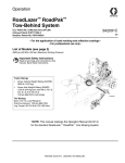
Programmable Skipline Controller for
RoadLazer™ RoadPak™ Line Striping System
3A1215C
EN
- For the application of road marking reflective materials - For professional use only -
Model 24F472 - Controller Only
Model 24G632 - Controller, Cable, Remote Switch, and Bracket
Important Safety Instructions
Read all warnings and instructions in this
manual. Save these instructions.
A
B
C
D
E
F
SY
S
DE TEM
LA
Y
PO
ST
A
SK RT
SP IP
AC
E
BE
W
ONER
AD
SO
ME
N
NU
ME
NU
BE
AD
OF
F
TE
ST
P
SKROG
IPL RA
INE MM
CO ABL
NT E
RO
L
RE
SE
T
HO
LD
ti16358a
ATTENTION!
To configure the Programmable Skipline Controller to operate with a
single wheel tow-behind RoadLazer system (models 231378, 231571
and 231571), see page 7.
Warnings
Warnings
The following warnings are for the setup, use, grounding, maintenance, and repair of this equipment. The exclamation point symbol alerts you to a general warning and the hazard symbols refer to procedure-specific risks. When
these symbols appear in the body of this manual, refer back to these Warnings. Product-specific hazard symbols and
warnings not covered in this section may appear throughout the body of this manual where applicable.
WARNING
WARNING
EQUIPMENT MISUSE HAZARD
Misuse can cause death or serious injury.
• Do not operate the unit when fatigued or under the influence of drugs or alcohol.
• Do not exceed the maximum working pressure or temperature rating of the lowest rated system
component. See Technical Data in all equipment manuals.
• Use fluids and solvents that are compatible with equipment wetted parts. See Technical Data in all
equipment manuals. Read fluid and solvent manufacturer’s warnings. For complete information about
your material, request MSDS from distributor or retailer.
• Do not leave the work area while equipment is energized or under pressure. Turn off all equipment
and follow the Pressure Relief Procedure when equipment is not in use.
• Check equipment daily. Repair or replace worn or damaged parts immediately with genuine
manufacturer’s replacement parts only.
• Do not alter or modify equipment.
• Use equipment only for its intended purpose. Call your distributor for information.
• Route hoses and cables away from traffic areas, sharp edges, moving parts, and hot surfaces.
• Do not kink or over bend hoses or use hoses to pull equipment.
• Keep children and animals away from work area.
• Comply with all applicable safety regulations.
2
3A1215C
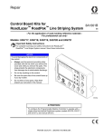
Component Identification and Function
Component Identification and Function
P
N
R
L
T
A
B
C
D
E
SYSTEM
DELAY
F
START
SKIP
SPACE
BEADS ON
S
BEAD TEST
MENU
MENU
K
POWER
ON
OFF
RESET
J
HOLD
PROGRAMMABLE
SKIPLINE CONTROL
G
ti16359a
H
Switch / Indicator
A - F Menu Controls
Explanation
Provides menu specific commands as display on LCD screen. Provides skipline paint and cycle
distance storage for instant change. Press and hold button to store pattern.
G
Power ON/OFF
switch
ON enables battery DC power to the Skipline Control. OFF removes power from the Control and
grounds the engine spark-plug. Engine can not be started when this switch is in the OFF position.
NOTE: This switch is also used to perform an emergency shutdown of the entire system.
H
Paint gun switches
1, 2 and 3
Enables/disables paint guns 1, 2 and 3. Up – skip line. Center – off. Down – continuous line. In
skipline mode, a new cycle will be activated each time unless another switch is already activated.
J
RESET/HOLD switch
HOLD disables paint guns 1, 2 and 3 and resets the internal cycle counter. RESET resets the
internal cycle counter but does not affect continuous line activity. If switch is held in RESET, a
new cycle will not begin until the switch is released.
K
switch
Used in conjunction with the arrow switches to adjust the paint line position to match a previously
painted line.
allows the dash line to be moved forward.
moved closer. The
allows the dash line to be
switch adjusts the position by 1/10’ every time it is toggled.
L
BEADS ON/BEADS
TEST
Enables/disables bead gun BEADS ON (up) – beads start to flow when paint guns start to paint.
Center – off. BEADS TEST (down) – continuous bead flow.
M
I/O cable port
The control cable connects here and at the striping system. The cable also brings in 12 VDC from
the striping system. See page 19.
N
Start Skip Space
Choose between starting with paint or space in skip line.
P
SYSTEM DELAY
ON/OFF
OFF – the paint guns and RESET/HOLD respond immediately. ON – the paint gun switches 1, 2
and 3; and RESET/HOLD switch are delayed by the preset system delay distance.
R
MENU arrow
switches
Used to switch between menus, adjusting values and resetting values.
S
Arrow switches
Used in conjunction with the Skipline Controller’s menus to adjust on-screen values.
T
Remote control
switch
Overrides the RESET/HOLD switch (J) when activated.
3A1215C
3
Installation
Installation
Operation
Mount Programmable Skipline
Control
General
To reduce the risk of serious injury, mount the
Skipline Controller where it is easily visible and will
not interfere with your view of the road. It should take
no longer to look at the controller than it does to look
at a rear-view mirror.
To reduce the risk of serious injury, make sure that
the Skipline Controller is turned OFF whenever you
service any part of the RoadLazer system or leave
the RoadLazer unattended.
•
All adjusted values remain in memory during power
down.
•
UP/DOWN: Numbers change faster when button is
pressed for more than 2 seconds.
•
Standard numbers are adjustable to 1/10 foot.
•
Metric numbers are adjustable to 1/50 meter.
Connect the Control Cable
•
Clean all connections of dirt, burrs, moisture, et. before
connecting them to the system.
NOTE: The controller must be calibrated in the units
that you desire to use.
•
Paint and cycle length are adjustable from 0.0 to
999.9 feet. or 0.0 to 99.99 meter.
•
Footage counters read out to 999,999.
•
BEAD ON/OFF and PAINT ON/OFF delays are
adjustable.
•
Pump output constant is adjustable from 0.0000 to
0.9999 gallons (liters)/stroke.
Place the Control in a position that is comfortable and
easy to use. If you decide to mount the control, mount
the 0.50” (13mm) wide mounting bracket to a solid location.
4
3A1215C
Operation
Menus
Information Readout (Startup/Main Menu)
Measuring Counter: Resets every time HOLD/RESET is activated.
Switch (J) must be in HOLD position
See System Delay
Example, page 9.
!
"#$%
!%
The First Menu is used to set the paint length of a skip line
and the frequency of that length.
1.
Set paint length with adjacent arrows.
2.
Set cycle length with adjacent arrows.
ti16373a
AVERAGE MILS (MIC): Continuously displays line thickness based on accumulated distance and material usage
from application totals in next menu.
NOTE: To store current skip line, press and hold any Menu
Control button (A - F) to assign the skip line to that button.
Application Totals
(
&
'
'
(*
(
)
(
)
+,
1(
(
)
(
234
23
23
0$
!
+,
-
.#/./#$%
,
The Counter Menu measures the actual paint distance in
feet (meters) from each paint gun. This menu also measures the gallons (liters) of paint sprayed by guns 1, 2, and
3. The average rate is calculated in the row at the bottom of
the screen based on line width.*
(
&
'
'
(*
(
)
(
)
ti16374a
NOTE: The DOUBLE row indicates when Gun 1 and Gun 2
are on at the same time.
$-!
##
!
+,
-
.#/./#$%
5 "#//%
5 )
"#//%
5 "#//%
#6
5$/!
0$
!
#%
,/
!!
Audible Speed Indicator™
!!
/#5
(7
+
,,
!
,,
8-#
9!! :
;
5 <
!
+
8/=
9!! :
>
5 <
ti16375a
The Speed Alarm Menu allows you to set the speed range (mph) that you would like to work within. The controller will beep
rapidly when you exceed the upper limit, and slowly when you fall below the lower limit.
3A1215C
5
Operation
Distance Calibration
$#%.!
#/$9#$%
5 #/$9#$%
!
%
!/#6
!
#?!
#6
!
$#"%$.
$#%.!
#/$9#$%
#
0$
#@!/
$#%.!
The Distance Calibration Menu is used to calibrate the
system against a measured distance (see Distance
Calibration Procedure, page 9).
2. Press
course.
1. Use adjacent arrows to enter the length of the measured course.
3. Press
ti16376a
at the beginning of the measured
at the end of the measured course.
NOTE: Distance accuracy is based on calibration. Use a
good quality measuring tape.
Pump Calibration
$#%.!
#/$9#$%
5 #/$9#$%
!
%
!/#6
!
#?!
#6
!
$#"%$.
5 #/$9#$%
0$
5 6./!
!
#//%
2A
ti16381a
The Pump Calibration Menu is used to adjust the unit of
measurement for accurate material usage in gallons or
liters.
2. Use adjacent arrows to change pump cycles per
unit volume (RPS 2900 preset value is 14.9, RoadLazer Tow Behind is 37. Value may need adjusting
due to viscosity of material)
1. Press
to toggle between units for display measurements.
Set Gun Delays
$#%.!
#/$9#$%
5 #/$9#$%
!
%
!/#6
!
#?!
#6
!
#%"#"!B$#"%$.
#$%
%
!/#6
!$%"
*!#
%
The Set Gun Delays Menu is used to synchronize paint
and bead guns in inches (cm). Incrementing value is
based on the resolution of the distance sensor.
NOTE: In the event of no distance travel sensing the
guns will default to a 1 second delay.
6
0$
#$%
%
%
!/#6
3
#$%
%
--
!/#6
3
ti16377a
NOTE: Follow on-screen instructions.
1. Press
Gun.
to switch between Bead Gun and Paint
2. Use adjacent arrows to change ON/OFF Delay
Distance.
3A1215C
Operation
Setup
A
B
C
D
E
F
Distance Calibration
Pump Calibration
Set Gun Delays
Setup
Marker Layout Mode
Diagnostics
A Distance Units
B GALLONS or LITERS
D
C Display SPACE or CYCLE
D Adjust Display Contrast
E Bead Gun Enable/Disable
F System Type
ti16378b
Distance Units
Changing units will reset
to factory settings
A
A English
B Metric
ft/in/mph
m/cm/kph
C Exit
Press A or B to switch English or Metric Units.
B
Press to choose between GALLONS or LITERS
C
Press to choose between SPACE or CYCLE
to be displayed on the main menu.
Adjust Display Contrast
A Reset to factory default
D
B Exit
Current Setting: Factory Default
CHANGE
1. Use adjacent arrow to change the display contrast.
2. Press “A” to reset to factory default setting.
Bead Gun Solenoids
A Solenoid 2 ENABLE
E
B Solenoid 4
ENABLE
C Solenoid 6 ENABLE
DISABLED
DISABLED
DISABLED
D Exit
This menu allows the user to turn off individual bead gun solenoids.
1. Press “A” to ENABLE/DISABLE solenoid 2.
2. Press “B” to ENABLE/DISABLE solenoid 4.
3. Press “C” to ENABLE/DISABLE solenoid 6.
Configure control to connect to
original single wheel tow-behind
Roadlazer system?
F
A Yes
B NO - cancel with no changes
3A1215C
7
Operation
Marker Layout Mode
#?!
#6
!
$#%.!
#/$9#$%
5 #/$9#$%
!
%
!/#6
!
#?!
#6
!
#%"#"!B$#"%$.
1_`
4
_)`
_`
_2`
_q`
_>`
_v`
_;`
{
,
|
8!.:
q
ti16379a
NOTE: To operate Marker Layout Mode, you must be in the Marker Layout Mode Menu.
Choose a spray gun and toggle that switch to the skipline setting.
Change Value
DOT Size (sec)
Set space sizes up to 8 consecutive measurements. By leaving zeros in any space, Marker Layout Mode will skip to the
next measurement in a continuous loop.
The amount of time the gun will be activated.
NOTE: Lowering system pressure may help produce smaller
more precise DOTS.
Marker Layout Mode Example:
48.00 ft
8.00 ft
16.00 ft
4.00 ft
4.00 ft
4.00 ft
4.00 ft
#?!
#6
!
1_`
;4
_)`
2
_`
2
_2`
>
_q`
2
_>`
2
_v`
;
_;`
ti16733a
8.00 ft
{
1.
Set space sizes.
2.
Select DOT SIZE (amount of time gun activates).
,
3.
Select one or more guns in skip line.
|
8!.:
q
4.
Activate with HOLD/RESET switch.
Diagnostics
ROADLAZER ROADPAK
Diagnostics
B Exit
Distance
Pump 1
Pump 2
SOLENOIDS
1 2 3 4 56
0
0
0
BEADS ON
SWITCH TEST
CAUTION
SOLENOIDS WILL
STILL ACTUATE
BEAD TEST
ADV
RET
RESET
A Reset
counters
1
2
Distance - Counts 50 +/- 2 pulses per revolution of the wheel. Input can be checked
by spinning the RoadPak gun arm wheel.
Pump 1 and Pump 2 - Counts one pulse per complete cycle/stroke.
3
HOLD
ROADLAZER TOW BEHIND
Diagnostics
B Exit
gun safety ON OFF
Distance
0
Pump 1
0
Pump 2
0
Pump 3
0
A Reset
counters
This menu is used to verify inputs from control box switches and sensors on the system, as well as to check if the solenoids are functioning properly. NOTE: Solenoid
will still be active during the test, which could result in turning the paint and bead
guns ON and OFF.
SOLENOIDS
1 2 3 4 56
BEADS ON
SWITCH TEST
CAUTION
SOLENOIDS WILL
STILL ACTUATE
BEAD TEST
ADV
RET
RESET
1
2
3
Switches: The darkened box indicates the position of the switch. Toggle each switch
individually and the darkened box should move to the new location if functioning
properly. If the darkened box does not move, the switch is not functioning properly
and will most likely need to be replaced.
Solenoids - Checks for presence of solenoid valve in system. A darkened box indicates solenoid is recognized by the control box. Solenoids will not be recognized with
gun arm in up position when mechanical safety switch is used. Solenoid bank will not
appear if power is not present.
HOLD
ti17006b
8
3A1215C
Operation
Distance Calibration Procedure
NOTE: Although the RoadLazer is calibrated prior to
shipping, the sensor will need to be recalibrated periodically due to wheel wear, and also whenever the gun-arm
wheel is replaced.
NOTE: Before recalibrating, ensure that the gun-arm
wheel is inflated to 40 psi. and verify the wheel is the
proper number of revolutions (see Diagnostics, page
8).
1. Measure and tape off an exact distance up to 1000
ft. Suggested distance is 300 ft - 500 ft.
NOTE: Any error made in this measurement causes
inaccurate line lengths.
2. Access the Distance Calibration Menu.
3. Use adjacent arrows to enter the length of the measured course.
4. Drive the RoadLazer to the beginning of the measured course. Line up the gun arm wheel exactly on
the first mark.
5. Press
button.
7. Press
button.
8. The system is now calibrated.
System Delay Set-Up
The start and stop of the guns in either solid lines or
skiplines may be delayed by a specified distance. The
One Operator System Delay™ is designed to make the
striping job a one person operation by eliminating the
need to look back at the guns to trigger them at the correct time. With the System Delay set, all gun activity is
controlled using the mechanical pointer reference point
on the road ahead of the vehicle.
1. Enable the system Delay Setup Menu.
2. Sight the mechanical pointer with start of paint stripe
(B).
3. Measure delay distance from start of paint stripe to
gun. Measure from (A) to (B).
4. Enter measured delay distance with adjacent
arrows.
When system delay is ON, all gun switches including
HOLD/RESET will be delayed by the distance set in system delay.
6. Driver the RoadLazer in a straight line to the mark at
the end of the measured course. Stop with the gun
arm wheel exactly on the second mark.
A
B
ti16418a
3A1215C
9
Operation
Example: Painting Two Solid Lines
with the One-Operator System
Delay™ On
B
1. Turn on System Delay.
2. Set guns 1 and 2 in the solid position and the
RESET/HOLD switch in the hold position.
Reset
1
2
3
Hold
ti16401a
3. Align the mechanical reference point with the beginning of the area to be painted (A).
4. Toggle the REST/HOLD button to center and drive
the course. This enables the selected guns to begin
painting when Point A is reached.
Reset
1
2
3
Hold
ti16402a
5. When the mechanical pointer reaches the end of the
desired course (B), toggle the RESET/HOLD switch
to hold. Continue driving until the guns stop spraying.
ti6408a
A
Reset
1
2
3
Hold
ti16401a
NOTE: For painting single lines, toggle either gun 1 or 2
to Solid, and the unused gun to center.
ti16392a
10
3A1215C
Operation
Skipline Applications with
One-Operator System Delay™ On
1. Turn on System Delay.
C
2. Load the cycle and paint length of the skipline to be
painted using the First Menu.
3. Align the mechanical pointer with point A.
4. Set gun 1 to Skip, and toggle the HOLD/RELEASE
switch to center.
B
Reset
1
2
3
Hold
ti16399a
5. When the mechanical point reaches point B, set gun
2 to solid
.
Reset
1
2
3
Hold
ti16400a
6. When the mechanical point reaches point C, return
gun 2 to center.
A
Reset
1
2
ti6406a
3
Hold
ti16399a
ti16392a
3A1215C
11
Troubleshooting
Troubleshooting
Problem
Control will not turn on.
Cause
12 VDC power supply low, or disconnected.
Solution
Connect the I/O cable.
Charge the RoadLazer battery.
Check the battery connections.
Guns will not spray.
Various causes.
Toggle RESET on the controller.
Check the paint supply.
Check the gun ball valves. See manual 306861.
Check the RoadLazer and engine
fuses. See manual 308611 or 3A1214
and separate engine manual.
MPH readout reads zero, or inconsistent reading.
Improper sensor alignment.
Sensor should be .03 in. from the timing gear, and centered.
Glass beads miss a portion of a stripe
when turned on.
Paint and bead gun delays not set
properly.
Adjust Paint and Bead Gun Delay values.
Glass beads stay on longer than the
paint guns, wasting beads.
Bead Off Delay is too high.
Lower the Bead Off Delay value.
Skipline is longer than the actual programmed distance.
The gun solenoids are taking longer
to turn off than to turn on.
Increase the value of the Paint Gun
on Delay.
Guns will not stop spraying.
The system delay is set to ON while
the vehicle is stopped.
Turn the Skipline Controller’s main
power switch OFF.
Gun needle and seat are worn out.
Replace. See manual 308613.
12
3A1215C
Troubleshooting
Control Cable Diagram for RoadPak
System
Contact
1
2
3
4
5
6
7
8
9
10
11
12
13
14
15
16
17
18
Description
12 VDC
Leave Open - Do Not Connect
Leave Open - Do Not Connect
Sensor, pump (1)
Sensor, pump (2)
Paint Gun (1) Solenoid 1
Paint Gun (2) Solenoid 3
Paint Gun (3) Solenoid 5
Bead Gun (1) Solenoid 2
Bead Gun (2) Solenoid 4
Bead Gun (3) Solenoid 6
Engine Shutdown (ground)
Ground **
Ground **
Ground **
Sensor Distance
Ground **
Leave Open - Do not connect
** All ground pins MUST be connected to ground
++ Input for pull-up/PNP/Sourcing Sensor
Action
Supply Voltage
4
Input
Input
Output (1 amp Max)
Output (1 amp Max)
Output (1 amp Max)
Output (1 amp Max)
Output (1 amp Max)
Output (1 amp Max)
Input
9
5
1
2
3
6
8
10
7
11
12
15
13
14
ti6355a
16
17
18
Alternative Pin Arrangement for
OEM Applications
NOTE: Pin 18 must be grounded to activate this configuration.
Contact
1
2
3
4
5
6
7
8
9
10
11
12
13
14
15
16
17
18
Description
12 VDC
Sensor Distance ++
Sensor, safety, guns
Sensor, pump (1)
Sensor, pump (2)
Paint Gun (1) Solenoid 1
Paint Gun (2) Solenoid 3
Paint Gun (3) Solenoid 5
Bead Gun (1) Solenoid 2
Bead Gun (2) Solenoid 4
Bead Gun (3) Solenoid 6
Engine Shutdown (ground)
Ground **
Ground **
Ground **
Sensor Pump (3)
Ground **
Ground **
Action
Supply Voltage
Input ++
Input
Input
Input
Output (1 amp Max)
Output (1 amp Max)
Output (1 amp Max)
Output (1 amp Max)
Output (1 amp Max)
Output (1 amp Max)
Input
NOTE: All inputs are for open-collector/pull-down/NPN/Sinking
Sensors unless otherwise noted.
3A1215C
13
Parts
Parts
4
BE
1
10
EM
ST
SY LAY
DE
SO
AD
T
AR
ST IP
SK E
AC
SP
BE
AD
TE
N
ST
F
E
D
ME
ME
NU
NU
C
B
SE
RE
A
T
LD
HO
BE
EM
ST
SY LAY
DE
S
AD
T
AR
ST IP
SK E
AC
SP
ON
R
WE
PO N
O
ST
D
EA
TE
B
F
OF
E
D
ME
ME
F
10
LE
AB OL
MM TR
RA ON
OG E C
PR LIN
IP
SK
NU
NU
C
B
A
RE
3
SE
T
OLD
H
R
WE
PO N
O
F
6
7
LE
AB OL
MM TR
RA ON
OG E C
PR LIN
IP
SK
OF
2
ti16360a
5
8
Ref.
1
2
3
4
5
6
7
8
9
10
Part
Description
24F472 CONTROLLER, skipline (includes 2)
KNOB, mounting
24F469 CABLE, control
113617 SWITCH, remote
191864 BRACKET, mounting
24G720 KIT, board, display, RoadLazer
24G717 KIT, board, switch, toggle
24G719 KIT, board, switch, power
24G718 KIT, board, control, switch, guns
24G721 KIT, switch, membrane
9
Qty.
1
2
1
1
1
1
1
1
1
1
Technical Data
Electrical requirements
Control
Sender input
Ground
Gun output switching to ground
Reverse polarity and noisy spikes
Operating speed range
Operating temperature
Weight
Dimensions
14
12 Vdc
12 Vdc
Negative
2A max
Protected
Up to 20 mph (450 pulses/sec)
32-130° F
3
7.25 in. x 4.50 in. x 2.25 in.
(184 mm x 114 mm x 57 mm)
3A1215C
Notes
Notes
3A1215C
15
Graco Standard Warranty
Graco warrants all equipment referenced in this document which is manufactured by Graco and bearing its name to be free from defects in
material and workmanship on the date of sale to the original purchaser for use. With the exception of any special, extended, or limited warranty
published by Graco, Graco will, for a period of twelve months from the date of sale, repair or replace any part of the equipment determined by
Graco to be defective. This warranty applies only when the equipment is installed, operated and maintained in accordance with Graco’s written
recommendations.
This warranty does not cover, and Graco shall not be liable for general wear and tear, or any malfunction, damage or wear caused by faulty
installation, misapplication, abrasion, corrosion, inadequate or improper maintenance, negligence, accident, tampering, or substitution of
non-Graco component parts. Nor shall Graco be liable for malfunction, damage or wear caused by the incompatibility of Graco equipment with
structures, accessories, equipment or materials not supplied by Graco, or the improper design, manufacture, installation, operation or
maintenance of structures, accessories, equipment or materials not supplied by Graco.
This warranty is conditioned upon the prepaid return of the equipment claimed to be defective to an authorized Graco distributor for verification of
the claimed defect. If the claimed defect is verified, Graco will repair or replace free of charge any defective parts. The equipment will be returned
to the original purchaser transportation prepaid. If inspection of the equipment does not disclose any defect in material or workmanship, repairs
will be made at a reasonable charge, which charges may include the costs of parts, labor, and transportation.
THIS WARRANTY IS EXCLUSIVE, AND IS IN LIEU OF ANY OTHER WARRANTIES, EXPRESS OR IMPLIED, INCLUDING BUT NOT
LIMITED TO WARRANTY OF MERCHANTABILITY OR WARRANTY OF FITNESS FOR A PARTICULAR PURPOSE.
Graco’s sole obligation and buyer’s sole remedy for any breach of warranty shall be as set forth above. The buyer agrees that no other remedy
(including, but not limited to, incidental or consequential damages for lost profits, lost sales, injury to person or property, or any other incidental or
consequential loss) shall be available. Any action for breach of warranty must be brought within two (2) years of the date of sale.
GRACO MAKES NO WARRANTY, AND DISCLAIMS ALL IMPLIED WARRANTIES OF MERCHANTABILITY AND FITNESS FOR A
PARTICULAR PURPOSE, IN CONNECTION WITH ACCESSORIES, EQUIPMENT, MATERIALS OR COMPONENTS SOLD BUT NOT
MANUFACTURED BY GRACO. These items sold, but not manufactured by Graco (such as electric motors, switches, hose, etc.), are subject to
the warranty, if any, of their manufacturer. Graco will provide purchaser with reasonable assistance in making any claim for breach of these
warranties.
In no event will Graco be liable for indirect, incidental, special or consequential damages resulting from Graco supplying equipment hereunder, or
the furnishing, performance, or use of any products or other goods sold hereto, whether due to a breach of contract, breach of warranty, the
negligence of Graco, or otherwise.
FOR GRACO CANADA CUSTOMERS
The Parties acknowledge that they have required that the present document, as well as all documents, notices and legal proceedings entered into,
given or instituted pursuant hereto or relating directly or indirectly hereto, be drawn up in English. Les parties reconnaissent avoir convenu que la
rédaction du présente document sera en Anglais, ainsi que tous documents, avis et procédures judiciaires exécutés, donnés ou intentés, à la suite
de ou en rapport, directement ou indirectement, avec les procédures concernées.
Graco Information
For the latest information about Graco products, visit www.graco.com.
TO PLACE AN ORDER, contact your Graco distributor or call 1-800-690-2894 to identify the nearest distributor.
All written and visual data contained in this document reflects the latest product information available at the time of publication.
Graco reserves the right to make changes at any time without notice.
For patent information, see www.graco.com/patents
Original instructions. This manual contains English. MM 3A1215
Graco Headquarters: Minneapolis
International Offices: Belgium, China, Japan, Korea
GRACO INC. P.O. BOX 1441 MINNEAPOLIS, MN 55440-1441
Copyright 2010, Graco Inc. is registered to ISO 9001
www.graco.com
Revised November 2013