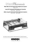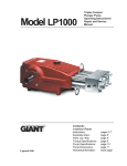
1
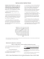
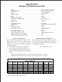
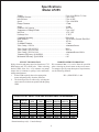
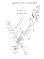
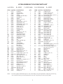
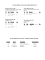
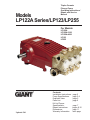
Triplex Ceramic Plunger Pump Operating Instructions/ Repair and Service Manual Models LP122A Series/LP123/LP255 For Models: LP122A LP122A-3100 LP122A-4000 LP123 LP255 Updated 5/01 Contents: Installation Instructions: Pump Specifications: Exploded View: Parts List: Kit List/Torque Specifications: Repair Instructions: Dimensions: Warranty Information: page 2 page 3-4 page 5 page 6 page 7 pages 8-10 page 11 back page INSTALLATION INSTRUCTIONS Installation of the Giant Industries, Inc., pump is not a complicated procedure, but there are some basic steps common to all pumps. The following information is to be considered as a general outline for installation. If you have unique requirements, please contact Giant Industries, Inc. or your local distributor for assistance. 1. The pump should be installed flat on a base to a maximum of a 15 degree angle of inclination to ensure optimum lubrication. 2. The inlet to the pump should be sized for the flow rate of the pump with no unnecessary restrictions that can cause cavitation. Teflon tape should be used to seal all joints. If pumps are to be operated at temperatures in excess of 1600 F, it is important to insure a positive head to the pump to prevent cavitation. See NPSH curve. 3. The discharge plumbing from the pump should be properly sized to the flow rate to prevent line pressure loss to the work area. It is essential to provide a safety bypass valve between the pump and the work area to protect the pump from pressure spikes in the event of a blockage or the use of a shut-off gun. 4. Use of a dampener is necessary to minimize pulsation at drive elements, plumbing, connections, and other system areas. The use of a dampener with Giant Industries, Inc. pumps is optional, although recommended by Giant Industries, Inc. to further reduce system pulsation. Dampeners can also reduce the severity of pressure spikes that occur in systems using a shut-off gun. A dampener must be positioned downstream from the unloader. 5. Crankshaft rotation on Giant Industries, Inc. pumps should be made in the direction designated by the arrows on the pump crankcase. Reverse rotation may be safely achieved by following a few guidelines available upon request from Giant Industries, Inc. Required horsepower for system operation can be obtained from the charts on pages 3. 6. Before beginning operation of your pumping system, remember: Check that the crankcase and seal areas have been properly lubricated per recommended schedules. Do not run the pump dry for extended periods of time. Cavitation will result in severe damage. Always remember to check that all plumbing valves are open and that pumped media can flow freely to the inlet of the pump. Finally, remember that high pressure operation in a pump system has many advantages. But, if it is used carelessly and without regard to its potential hazard, it can cause serious injury. IMPORTANT OPERATING CONDITIONS Failure to comply with any of these conditions invalidates the warranty. 1. Prior to initial operation, add oil to the crankcase so that oil level is between the two lines on the oil dipstick. DO NOT OVERFILL. 2. Pump operation must not exceed rated pressure, volume, or RPM. A pressure relief device must be installed in the discharge of the system. Use SAE 90 Industrial gear oil 3. Acids, alkalines, or abrasive fluids cannot be pumped unless approval in writing is obtained before operation from Giant Industries, Inc. Crankcase oil should be changed after the first 50 hours of operation, then at regular intervals of 500 hours or less depending on operating conditions. 4. Run the pump dry approximately 10 seconds to drain the water before exposure to freezing temperatures. NOTE: Contact Giant Industries for Service School Information. Phone: (419)-531-4600 2 Specifications Models LP122A Series/LP123 Volume ............................................................................................... Up to 39.0 GPM (147.6 l/m) Discharge Pressure ............................................................................ Up to 2000* PSI (138* Bar) Inlet Pressure ..................................................................................... Up to 90 PSI (6.2 Bar) Speed ................................................................................................. Up to 885 RPM Plunger Diameter ............................................................................... 42 mm Stroke ................................................................................................. 42 mm Crankcase Oil Capacity ..................................................................... 116 fl.oz. Temperature of Pumped Fluids ......................................................... Up to 160oF (71oC) Inlet Port ............................................................................................ 1-1/2" NPT Discharge Port ................................................................................... 1" NPT Crankshaft Mounting ......................................................................... Either Side Shaft Rotation .................................................................................... Top of Pulley Towards Fluid End Weight................................................................................................ 116 lbs. Crankshaft Diameter.......................................................................... 35 mm Valve Casing - LP122A ..................................................................... Aluminum Bronze Valve Casing - LP123 ........................................................................ Brass Valve Casing - LP122A-4000 ............................................................ 303 S.S. Valve Casing - LP122A-3100 ............................................................ Aluminum Bronze-Nickle Volumetric Efficiency @ 800 RPM................................................... 0.96 Mechanical Efficiency @ 800 RPM.................................................. 0.85 HORSEPOWER INFORMATION We recommend that a 1.1 service factor be specified when s electing an electric motor as the power source. To compute specific pump horsepower requirements, use the following formula: PULLEY INFORMATION Pulley selection and pump speed are based on a 1725 RPM motor and "B" section belts. When selecting desired GPM, allow for a ±5% tolerance on pumps output due to variations in pulleys, belts and motors among manufacturers. 1. Select GPM required, then select appropriate motor and pump pulley from the same line. 2. The desired pressure is achieved by selecting the correct nozzle size that corresponds with the pump GPM. HP = (GPM X PSI) / 1440 Pump speeds of 640 RPM and above require a minimum inlet pressure of 12 psig. Pump speeds of 805 RPM and above require a minimum inlet pressure of 14 psig. LP122A SERIES/LP123 PULLEY SELECTION AND HORSEPOWER REQUIREMENTS GPM 22.3 24.7 28.5 30.9 33.4 35.6 39.4 * PUMP PULLEY 12.75" 12.75" 12.75" 12.75" 12.75" 12.75" 12.75" MOTOR PULLEY 3.95" 4.35" 4.95" 5.35" 5.75" 6.15" 6.50" RPM 600 PSI 800 PSI 500 555 640 695 750 800 885 9.6 10.6 12.2 13.2 14.3 15.3 16.9 12.7 14.1 16.3 17.7 19.1 20.3 22.5 *Intermittent duty only! - Consult factory! 3 1000 PSI 1300 PSI 2000 PSI* 15.9 17.6 20.4 22.1 23.9 25.4 28.1 20.7 22.9 26.5 28.7 31.0 33.1 36.6 31.9 35.3 40.7 44.1 47.7 50.9 56.3 Specifications Model LP255 Volume ............................................................................................... Up to 26.0 GPM (147.6 l/m) Discharge Pressure ............................................................................ Up to 2200* Inlet Pressure ..................................................................................... Up to 90 PSI Speed ................................................................................................. Up to 1000 RPM Plunger Diameter ............................................................................... 32 mm Stroke ................................................................................................. 42 mm Crankcase Oil Capacity ..................................................................... 116 fl.oz. Temperature of Pumped Fluids ......................................................... Up to 160oF Inlet Port ............................................................................................ 1-1/2" NPT Discharge Port ................................................................................... 1" NPT Crankshaft Mounting ......................................................................... Either Side Shaft Rotation .................................................................................... Top of Pulley Towards Fluid End Weight................................................................................................ 116 lbs. Crankshaft Diameter.......................................................................... 35 mm Valve Casing - LP122A ..................................................................... Aluminum Bronze Valve Casing - LP123/LP255 ............................................................ Brass Valve Casing - LP122A-4000 ............................................................ 303 S.S. Valve Casing - LP122A-3100 ............................................................ Aluminum Bronze-Nickle Volumetric Efficiency @ 800 RPM................................................... 0.96 Mechanical Efficiency @ 800 RPM.................................................. 0.85 HORSEPOWER INFORMATION We recommend that a 1.1 service factor be specified when s electing an electric motor as the power source. To compute specific pump horsepower requirements, use the following formula: PULLEY INFORMATION Pulley selection and pump speed are based on a 1725 RPM motor and "B" section belts. When selecting desired GPM, allow for a ±5% tolerance on pumps output due to variations in pulleys, belts and motors among manufacturers. 1. Select GPM required, then select appropriate motor and pump pulley from the same line. 2. The desired pressure is achieved by selecting the correct nozzle size that corresponds with the pump GPM. HP = (GPM X PSI) / 1440 LP255 PULLEY SELECTION AND HORSEPOWER REQUIREMENTS PUMP PULLEY 12.75" 12.75" 12.75" 12.75" 12.75" 12.75" 12.75" MOTOR PULLEY 3.95" 4.35" 4.95" 5.35" 5.75" 6.15" 6.50" RPM GPM 500 640 750 805 865 920 1000 13 16.6 19.5 20.9 22.5 23.9 26 1000 PSI 1500 PSI 2000 PSI 2200 PSI 9.3 11.9 13.9 14.9 16.1 17.1 18.6 13.9 17.8 20.9 22.4 24.1 25.6 27.9 *Intermittent duty only! - Consult factory! 4 18.6 23.7 27.9 29.9 32.1 34.1 37.1 20.4 26.1 30.6 32.8 35.4 37.6 40.9 Exploded View - LP122A Series/LP123/LP255 5 LP122A SERIES/LP123/LP255 PARTS LIST A = LP122A ITEM 1 2 4 5 6 8 9 10 10 11 11 12 12 13 13 14 15 16 17 17 20 20A 20B 21 22 23 24 24A 24B 25 28 29A 29B 29B 29C 29C 29D 29D 29E 29E 30 30 31 31A 31B 32 32A 33 35 35 35 35A 35A NOTE: B = LP123 C = LP122-4000 PART NO. 07759 13000 06085 07104 07186 06086 01009 01010 08093 01011 08094 07109 12137 07110 07182 07111 07112 07113 07114 08095 07116 07117 13001 07118 13242 13243 13340 13277 13278 13341 DESCRIPTION QTY. Crankcase 1 Oil Filler Plug 1 Crankcase Cover 1 O-Ring 1 Oil Sight Glass W/Gasket 1 Oil Dipstick 1 O-Ring 1 Screw, (A, B, C, E) 4 Screw, (D) 4 Spring Washer, (A, B, C) 5 Spring Washer, (D) 5 Oil Drain Plug, (A, B, C, E) 1 Oil Drain Plug, (D) 1 Gasket, (A, C) 1 Gasket, (B, D, E) 1 Bearing Cover 2 Crankshaft Seal 2 O-Ring 2 Hex Screw, (A, B, C, E) 8 HexScrew, (D) 8 Taper Roller Bearing 2 Fitting Disc, 0.1mm 2 Fitting Disc, 0.15mm 3 Shaft Protector 1 Crankshaft 1 Key 1 Connecting Rod Assy. 3 Hex Screw 6 Spring Washer 6 Crosshead Plunger Base Assy. 3 13232 Crosshead Pin 3 07735 Centering Sleeve 3 07736 Plunger Pipe (A-D) 3 13022 Plunger Pipe (E) 3 07737 Plunger Bolt, (A, B, C, E) 3 07737-0100 Plunger Bolt, (D) 3 07755 Copper Gasket, (A, B, C, E) 3 07761-0100 Gasket for Bolt, (D) 3 06087 Spacer Pipe, (A, B, C, E) 3 06618 Spacer Pipe, (D) 3 07789 Flinger (A, B, C, D) 3 07779 Flinger (E) 3 06120 Seal Retainer, Complete, (A, C) 3 06118 Oil Seal, (A, C) 3 07133 Radial Shaft Seal, (B, D, E) 3 06116 Oil Seal Retainer, (A, C) 3 06119 O-Ring, (A, C) 3 06117 Backup Seal, (A, C) 3 13342 Seal Sleeve, (A, B, C) 3 13342-0100 Seal Sleeve, (D) 3 06699 Seal Sleeve (E) 3 07740 O-Ring, (A, B, C, E) 3 06619 O-Ring, (D) 3 D = LP122A-3100 ITEM 35B 36 36 36A 36A 36A 37 39 39 39 40 40 41 41 41 42 42A 43 43 43 43 43 44 44 44A 44A 45 45 46 46A PART NO. 13141 13415 13025 13416 13416-0100 06700 06701 07744 07744-0100 13026 07745 13027 07746 06621-0100 06702 06589 07204-0100 13343 06625 13343-4000 13343-3000 06703 07748 07748-0100 07150 06620 07749 07749-0100 07750 07751 46A 07751-0100 47 48 48 48 48A 48A 49 49A 49B 50 50 50A 50A 52 53 54 54 54 55 55 55 07752 07753 06504 06089 12055 06577 07157 07158 07159 07423 07423-0100 07161 07755-0100 13020 06607 07756 06626 13321-0100 07757 06627 13322-0100 E = LP255 DESCRIPTION QTY. O-Ring (E only) 3 V-Sleeve, Weep (A-D) 3 V-Sleeve, Weep (E) 3 Pressure Ring, Weep, (A, B, C) 3 Pressure Ring, (D) 3 Pressure Ring (E) 3 Support Disc (E only) 3 Pressure Ring, (A, B, C) 3 Pressure Ring, (D) 3 Pressure Ring (E) 6 V-Sleeve (A, B, C, D) 6 V-Sleeve (E) 6 Support Ring, (A, B, C) 3 Support Ring, (D) 3 Support Ring (E) 3 Plug, (D only) 3 Steel Ring, (D only) 3 Valve Casing, (A) 1 Valve Casing, (B) 1 Valve Casing, (C) 1 Valve Casing, (D) 1 Valve Casing, (E) 1 Valve Seat, (A, B, C, E) 6 Valve Seat, (D) 6 O-Ring, (A, B, C, E) 6 O-Ring, (D) 6 Valve Plate, (A, B, C, E) 6 Valve Plate, (D) 6 Valve Spring 6 Valve Assy. Complete, (A, B, C, E) (#44, 44A, 45, 46, & 47) 6 Valve Assmebly Complete (D) (#44, 44A, 45, 46, & 47) 6 Spring Retainer 6 Plug, (A) 6 Plug, (B, E) 6 Plug, (C, D) 6 O-Ring, (A, B, C, E) 6 O-Ring, (D) 6 Stud Bolt 8 Nut 8 Washer 8 Plug, (A,B, E) 1 Plug, (C, D) 1 Gasket, (A, B,C, E) 1 Gasket, (D) 1 Disk for Crankshaft 1 Hexagon Screw 1 Plug 1" NPT, (A, C) 1 Plug 1" NPT, (B, E) 1 Plug 1" BSP, (D) 1 Plug 1-1/2" NPT, (A, C) 1 Plug, 1-1/4" NPT, (B, E) 1 Plug, 1" BSP, (D) 1 For LP122 pumps manufactured prior to 5/94, and needing weep seal replacement, change the pressure ring (36) to the newer style (p/n 13416) and use the new style weep seal (p/n 13415) in your pumps. 6 LP122A SERIES/LP123/LP255 PUMP REPAIR KITS Plunger Packing Kit Valve Assembly Kit # 09477 (LP122A, LP123, LP122A-4000) (for pumps manufatured after 4/98) LP122A. LP123, LP122A-4000, LP255 #09136 Item Part # Description Qty. Item Part # Description Qty. 35A 07740 O-ring 3 46A 07751 Valve Assembly, Complete 3 36 13415 V-Sleeve, Weep 3 48A 12055 O-Ring 3 40 07745 V-Sleeve 6 Plunger Packing Kit Valve Assembly Kit # 09535 (LP255) Item Part # Description Qty. LP122A-3100 #09305 35A 07740 O-ring 3 Item Part # 35B 13141 O-Ring 3 46A 07751-0100 Valve Assembly Complete 3 36 13025 V-Sleeve weep 3 48A 06577 3 40 13027 V-Sleeve 6 Description O-Ring LP122A SERIES/LP123/LP255 TORQUE SPECIFICATIONS Position Item# 10 17 24A 29C 48 49A 01010/08093 07114/08095 13277 07737/07737-0100 07753/06504/06089 07158 Description Screw, Cover Hex Screw, Bearing Cover Hex Screw, Connecting Rod Plunger Bolt Plug, Valve Nut, Stud Bolt 7 Torque Amount 125 in.-lbs. 125 in.-lbs. 250 in.-lbs. 26 ft.-lbs. 160 ft.-lbs. 60 ft.-lbs. Qty. LP122A Series/LP123 - Repair Instructions 44A 1. With a 30mm wrench, remove the six (6) plugs (48) from the valve casing (43). Inspect the o-rings (48A) and replace if necessary. Remove the complete valve assembly (46A) by threading a 12mm bolt into the spring retainer and pulling straight out. 5. If there are signs of oil leaking through the plunger oil seals, then replacment is neccessary.For LP122A & LP122A-4000, remove the plunger pipe (29B) before inspecting oil seals (31A & 33). For the LP123 & LP122A-3100 dissassemble the gear end and push out the seals from the back of the pump. 45 48 47 2. To disassemble the valve, screw the bolt into the retainer until the valve plate (45) presses the valve seat (44) out of the spring retainer. Examine all parts and replace if necessary. If the seat doesn’t come out, use a valve puller to remove. 36A 3. Remove the eight (8) hex nuts (49A) with a 19mm wrench. Tap the back of the manifold (43) with a rubber mallet to dislodge and slide off the studs. 44 36 35 35A 35B (LP255 only) 39 40 40 41 37 (LP255 only) 4. Remove the seal sleeve (35) from the manifold and/or crankcase. Remove the pressure rings (39&36A), v-sleeves (40&36), support ring (41) and o-rings (35A and 35B in Lp255A only) from the manifold and seal sleeve, respectively. For LP255 only, remove support ring (37). Examine seals carefully and replace if worn. Clean all parts. 29E 29A 29B 29D 29C 6. Inspect surface of plunger pipe (29B) carefully. Remove any chemical or mineral deposits taking care not to damage the surface of the plunger. If plunger pipe is worn, remove the plunger bolt (29C) , plunger pipe (29B) and spacer (29E). Replace worn parts necessary. Note: Always use a new copper gasket (29) when repairing the plunger assembly. 8 oil. 7. For LP122A & LP122A-4000 pumps, oil seal replacement can be accomplished by pulling the retainer forward out of the crankcase. The o-ring around the outside of the retainer should be replaced and lubricated with a light film of 8. The back-up seal (33) can be pried out of the back of the retainer (32) with a small screwdriver. To replace with new seal, lubricate edges of new seal, then squeeze outside edges of seal, forcing the seal to collapse into a figure 8. Tuck the two outside edges of the figure 8 into the rear of the retainer, making sure that the inner lip of the seal faces the oil. The seal may now be pressed firmly into place. 9. The front oil seal (31A) can now be removed by inserting a screwdriver through the rear of the retainer and tapping the seal out through the front of the retainer. Remove any excess old loc-tite from retainer. To replace oil seal, apply a light film of loc-tite around outside edges of seal. Tap seal firmly into the retainer with a wooden dowel making certain that the spring side of the seal is installed first and that the seal sits squarely in the retainer. TO REASSEMBLE PROCEED AS FOLLOWS: 29E 29A 10. For LP122A & LP122A-4000 pumps, generously lubricate the inside of the oil seals (31A & 33) and o-ring (32A). Next, place the seal retainer, complete (31) over the steel plunger base seat firmly into the crankcase. Replace the flinger (30). 29B 29D 29C 11. If previously disassembled thoroughly clean all exposed surfaces on the spacer (29E) and all exposed threads on the plunger bolt (29C) and the steel plunger base (25). Threads MUST be free of old loc-tite and any other material such as oil, grease, etc. This is necessary to ensure proper curing of new loc-tite. Giant recommends cleaning the threads with acetone or other suitable cleaner. Reassemble plunger assembly parts (29A, 29B, & 29E) using a new copper gasket (29D) and the cleaned plunger bolt (29C). Slide the bolt through the center of the four (4) pieces so that the threaded end is exposed. Apply several drops of loc-tite 243 (or equivalent) adhesive to the threads. Thread into steel plunger base and tighten to 26 ft.-lbs. BE CERTAIN ALL PARTS ARE CENTERED WITH THE BOLT! 9 36A 36 35 35A 35B (LP255 only) 39 12. Lubricate weep seal (36). Place, weep seal (36), and pressure ring (36A) into the seal sleeve (35). Assemble the o-ring (35A and 35B for LP255 only) onto seal sleeve and lubricate. 14. Press seal sleeve assembly into the manifold and seat firmly. Put the support ring (41) on plunger with v-side facing the manifold. 15. Place entire manifold/seal sleeve assembly over the studs and push firmly until seated 13. For LP255 pumps, insert support ring (37) into valve casing (43). Place support ring (41) and v-sleeves (40) into valve casing. 6 4 2 7 8 1 3 5 against the crankcase. 16. Tighten hex nuts (49A) in a crosswise pattern (shown above) to 60 ft.-lbs. 48A) and tighten to 160 ft.-lbs. 19. Fill crankcase with approximately 116 fluid ounces of Giant oil or equivalent SAE 90 industrial gear oil and check oil level of the crankcase with the dipstick. Proper level is center of two lines. Reinstall your Giant LP pump into your system. 17. Next, place valve assemblies (46A) into manifold after first lubricating the o-ring (44A). Seat firmly into manifold. 18. Replace plug with o-ring (48, & Contact Giant Industries or your local distributor for maintenance of the gear end of your pump. Phone: 419/531-4600 Contact Giant Industries for service school information. Phone: (419) 531-4600 10 11 GIANT INDUSTRIES LIMITED WARRANTY Giant Industries, Inc. pumps and accessories are warranted by the manufacturer to be free from defects in workmanship and material as follows: 1. For portable pressure washers and self-service car wash applications, the discharge manifolds will never fail, period. If they ever fail, we will replace them free of charge. Our other pump parts, used in portable pressure washers and in car wash applications, are warranted for five years from the dateof shipment for all pumps used in NON-SALINE, clean water applications. 2. One (1) year from the date of shipment for all other Giant industrial and consumer pumps. 3. Six (6) months from the date of shipment for all rebuilt pumps. 4. Ninety (90) days from the date of shipment for all Giant accessories. This warranty is limited to repair or replacement of pumps and accessories of which the manufacturers evaluation shows were defective at the time of shipment by the manufacturer. The following items are NOT covered or will void the warranty: 1. Defects caused by negligence or fault of the buyer or third party. 2. Normal wear and tear to standard wear parts. 3. Use of repair parts other than those manufactured or authorized by Giant. 4. Improper use of the product as a component part. 5. Changes or modifications made by the customer or third party. 6. The operation of pumps and or accessories exceeding the specifications set forth in the Operations Manuals provided by Giant Industries, Inc. Liability under this warranty is on all non-wear parts and limited to the replacement or repair of those products returned freight prepaid to Giant Industries which are deemed to be defective due to workmanship or failure of material. A Returned Goods Authorization (R.G.A.) number and completed warranty evaluation form is required prior to the return to Giant Industries of all products under warranty consideration. Call (419)-531-4600 or fax (419)-531-6836 to obtain an R.G.A. number. Repair or replacement of defective products as provided is the sole and exclusive remedy provided hereunder and the MANUFACTURER SHALL NOT BE LIABLE FOR FURTHER LOSS, DAMAGES, OR EXPENSES, INCLUDING INCIDENTAL AND CONSEQUENTIAL DAMAGES DIRECTLY OR INDIRECTLY ARISING FROM THE SALE OR USE OF THIS PRODUCT. THE LIMITED WARRANTY SET FORTH HEREIN IS IN LIEU OF ALL OTHER WARRANTIES OR REPRESENTATION, EXPRESS OR IMPLIED, INCLUDING WITHOUT LIMITATION ANY WARRANTIES OR MERCHANTABILITY OR FITNESS FOR A PARTICULAR PURPOSE AND ALL SUCH WARRANTIES ARE HEREBY DISCLAIMED AND EXCLUDED BY THE MANUFACTURER. GIANT INDUSTRIES, INC., 900 N. Westwood Avenue, P.O. Box 3187, Toledo, OH 43607 PHONE: (419) 531-4600, FAX: (419) 531-6836, www.giantpumps.com Ó Copyright 2001 Giant Industries, Inc. 05/01 LP122A/LP123/LP255.PM6