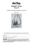
1
OVATION™ Series
Automatic Transfer Switch Systems
Installation, Operating and Maintenance Instructions
For Models:
• ATS1001D, ATS1001R
• ATS2001D, ATS2001R
• ATS2002R
Model ATS1001D
Model ATS1001R
Model ATS2001D
Model ATS2001R
Model ATS2002R
NOTE TO INSTALLER: Please leave this manual with the customer for future reference.
Una versión en español de este manual está disponible para descargar en nuestra página web www.gentran.com/support/installation
MODEL NUMBER ___________________________________SERIAL NUMBER ________________________________________________________
DATE OF INSTALLATION ______________________________DEALER NAME/PHONE ___________________________________________________
Please note your model number and serial number here for future reference. The serial number may be found inside the
enclosure, lower left or right.
OVATION™ Series Automatic Transfer Switches should NOT be used for Emergency Systems
(See NEC Articles 517 and 700), nor as a Legally Required System (see NEC Article 701), nor for
primary power in place of the electric utility or in life support applications.
This manual is published for informational purposes and should not be considered all inclusive. If further information is required, you
should consult Gen/Tran Corporation. Sale of product shown in this document is subject to terms and conditions outlined in
appropriate Gen/Tran selling policies or other contractual agreement between the parties. This document is not intended to and
does not enlarge or add to any such contract. Every effort has been made to ensure the accuracy and completeness of the
information in this manual. GenTran reserves the right to change and update the manual and product at any time without prior
notice.
No warranties, expressed or implied, including warranties of fitness for a particular purpose or merchantability, or warranties arising
from course of dealing or usage of trade, are made regarding the information, recommendations and descriptions contained herein.
In no event will Gen/Tran Corporation be responsible to the purchaser or user in contract, in tort (including negligence), strict liability
or otherwise for any special, indirect, incidental or consequential damage or loss whatsoever, including but not limited to damage or
loss of use of equipment, plant or power system, cost of capital, loss of power, additional expenses in the use of existing power
facilities, or claims against the purchaser or user by its customers resulting from the use of the information, recommendations and
description contained herein.
SAFETY PRECAUTION DEFINITIONS:
This symbol refers to a hazard or unsafe practice that can result in personal injury or product or property damage.
This symbol refers to a hazard or unsafe practice that can result in severe personal injury or death.
This symbol warns of immediate hazards that will result in severe personal injury, death or property damage.
PLEASE READ THIS MANUAL IN ITS ENTIRETY BEFORE ATTEMPTING TO UNPACK, ASSEMBLE, INSTALL, OPERATE
OR MAINTAIN THIS EQUIPMENT. HAZARDOUS VOLTAGES ARE PRESENT INSIDE TRANSFER SWITCH ENCLOSURES THAT CAN
CAUSE DEATH OR SEVERE PERSONAL INJURY. FOLLOW PROPER INSTALLATION, OPERATION AND MAINTENANCE PROCEDURES TO
AVOID THESE VOLTAGES.
TRANSFER SWITCH EQUIPMENT COVERED BY THIS DOCUMENT IS DESIGNED AND TESTED TO OPERATE WITHIN
ITS NAMEPLATE RATINGS. OPERATION OUTSIDE OF THESE RATINGS MAY CAUSE THE EQUIPMENT TO FAIL RESULTING IN DEATH,
SERIOUS BODILY INJURY AND/OR PROPERTY DAMAGE. ALL RESPONSIBLE PERSONNEL SHOULD LOCATE THE DOOR-MOUNTED
EQUIPMENT NAMEPLATE AND BE FAMILIAR WITH THE INFORMATION PROVIDED THEREIN.
High voltage in transfer panel components presents serious shock hazards that can result in severe personal injury
or death. Read and follow all directions before installation and use.
Keep the automatic transfer switch panel closed. Make sure only authorized personnel have access to the cabinet.
Due to the serious shock hazard from high voltages within the cabinet, all service and adjustments to the transfer switch must be
performed by an electrician or authorized service personnel. All possible contingencies which may arise during installation,
operation or maintenance, and all details and variations of this equipment do not purport to be covered by these instructions. If
further information is desired by purchaser regarding his particular installation, operation or maintenance of particular equipment,
contact Gen/Tran Corporation.
2
TABLE OF CONTENTS
SECTION 1 - INTRODUCTION........................................................................................................................................ 4
1.1 General Description ............................................................................................................................... 4
1.2 Standard Configurations ...................................................................................................................... 5
1.3 Typical Installations............................................................................................................................... 5
1.4 How the OVATION™ Series Automatic Transfer Switch Works .................................................. 6
1.5 Key Components..................................................................................................................................... 7
1.6 Standards Compliance .......................................................................................................................... 10
SECTION 2 – COMPATIBLE EQUIPMENT..................................................................................................................... 11
2.1 Compatible Generators......................................................................................................................... 11
2.2 Compatible Circuit Breakers................................................................................................................ 11
SECTION 3 – PREPARING FOR INSTALLATION.......................................................................................................... 12
3.1 Tools Required ........................................................................................................................................ 12
3.2 Unpacking/Inspection............................................................................................................................ 12
3.3 Mounting Location................................................................................................................................. 12
3.4 Planning, Selecting and Prioritizing Your Circuits.......................................................................... 12
SECTION 4 – INSTALLATION AND WIRING ................................................................................................................ 15
4.1 Standard Mounting Procedures.......................................................................................................... 18
4.2 Mounting Procedure for Two Load Centers..................................................................................... 20
4.3 Connecting the Low Voltage Cable to the OVATION™ Series ATS............................................. 20
4.4 Connecting the Low Voltage Cable to the Generator ................................................................... 21
4.5 Installing and Wiring PowerPause™ Load Management Modules............................................. 21
SECTION 5 – PROGRAMMING THE SYSTEM .............................................................................................................. 23
5.1 Setting Generator Size.......................................................................................................................... 23
5.2 Setting Generator Exercise Schedule and Transfer Option.......................................................... 23
5.3 User Interface Display LEDs ................................................................................................................. 23
5.4 User Interface Display/Control Module Functions.......................................................................... 24
SECTION 6 –STARTUP AND TESTING .......................................................................................................................... 25
6.1 Preliminary Checks................................................................................................................................. 25
6.2 Energizing the Transfer Switch ........................................................................................................... 25
6.3 Testing the Transfer Switch ................................................................................................................. 25
6.4 Programming the PowerPause™ Load Management Modules (if installed) ........................... 25
6.5 Re-Installing Covers and Labeling Circuits....................................................................................... 26
6.6 Generator Battery Monitoring............................................................................................................ 26
SECTION 7 – TROUBLESHOOTING ............................................................................................................................... 27
7.1 Basic Troubleshooting........................................................................................................................... 27
7.2 Troubleshooting Guide ......................................................................................................................... 27
SECTION 8 – MAINTENANCE AND SERVICE .............................................................................................................. 29
8.1 Maintenance............................................................................................................................................ 29
8.2 Factory Default Settings....................................................................................................................... 29
8.3 Product Registration ............................................................................................................................. 29
8.4 Exploded View and Replacement Parts Diagram
29
3
SECTION 1 - INTRODUCTION
1.1 General Description
The OVATION™ Series Automatic Transfer Switch (ATS) system, used in conjunction with a standby generator, provides a
convenient, economical way to maintain power in a home or business during a utility outage. The transfer switch senses when
utility power is lost, starts a permanently installed generator and transfers the connected loads to generator power, reversing the
sequence when utility power is restored.
Each OVATION™ Series ATS is tested and shipped from the factory with the following:
•
•
•
•
•
Two-pole service disconnect circuit breaker mechanically interlocked with generator source circuit breaker
Microprocessor based controller module with user display panel (UID).
Sub-panel for installing and connecting branch circuit breakers (branch circuit breakers sold separately).
Relay Kit (Model ATSRK) to connect certain stationary generators to the ATS
Options:
o The Control Module can accept up to 3 PowerPause™ Load Management modules (sold separately),
together with PowerPause™ Relay Boxes to dynamically manage up to six 240 VAC, up to 50A loads (or up
to 12 120VAC loads).
o A surge protection module can be factory or field installed.
o 22K AIC rated utility circuit breakers can be factory installed.
Transfer switches are used to protect critical electrical equipment and appliances against the loss of utility power. The appliance’s
normal power source is the utility, backed up by a secondary (generator) power source. The transfer switch is connected to both the
utility and generator sources and supplies the appliance with power from either the normal or secondary source. In the event that
the power is lost from the normal source (utility), the transfer switch system transfers the load to the secondary (generator) source.
Once utility power is restored to the home or building, the transfer switch transfers the load back to the normal source, and initiates
generator engine shutdown.
The following features are incorporated into each OVATION™ Series Automatic Transfer Switch:
• Automatic Transfer Switch and Load-center combined in one enclosure – Eliminates the need for a separate sub
panel; significantly reduces installation time, expense and complexity. Load-center accepts interchangeable type circuit breakers
from Siemens®, Square D®, Cutler-Hammer®, and GE®. See Section 2.2.
• Service Entrance Rated – All models carry service entrance ratings, eliminating the need for separate service entrance
equipment.
• Automatic Switching between utility and generator – When the transfer switch senses partial or total loss of electricity
for 5 seconds, it automatically starts the generator (equipped with appropriate remote-starting capabilities), and transfers the
load to generator power with circuit breaker based switching.
• Programmable Generator Exerciser – Tests generator on a regular interval (programmable to 0, 7, 14 or 28 days) to help
maintain a reliable generator.
• User Interface Display – User display with LEDs that indicate system status and situations requiring attention.
In the generator mode, optional PowerPause™ Load Management modules can manage up to six (6) 240 VAC (or 12 x 120 VAC)
connected loads based on parameters set up at installation. As generator power capacity becomes available, the OVATION™
transfer switch will attempt to turn on each PowerPause™-controlled load until the generator reaches 85% utilization. This allows a
larger number of loads – some intermittent – to be supported without nuisance tripping of the generator or investing in a larger
generator. Installing an OVATION™ Automatic Transfer Switch system with PowerPause™ Load Management modules, most
applications can utilize a generator that has 25% less output than standard installations with a conventional automatic transfer
switch, reducing initial installation and generator operating costs and maintenance.
The startup and shutdown sequence limits the generator from rapid, intermittent start-up and shutdown, thus prolonging generator
life. Here’s how your OVATION™ Series ATS works:
1. Waits up to 5 seconds after sustained power loss to start up generator.
2. Waits up to 15 seconds to transfer load to generator. Delay looking for successful utility power grid re-strike.
3. Once utility power is restored, the system waits one minute to transfer the load back to utility.
4. Five minutes after re-transfer, the system completes the generator cool down and shuts down.
4
1.2 Standard Configurations:
TABLE 1.2
Model
ATS1001D
ATS1001R
ATS2001D
ATS2001R
ATS2002R
# Circuits (1 Pole)
Enclosure Type
GENERATOR Main
UTILITY Main
Max Amps @ 240V
Max Generator Size
14
NEMA 1
100 A, 2 Pole
100 A, 2 Pole
100 Amps
Up to 25KW
16
NEMA 3R
100 A, 2 Pole
100 A, 2 Pole
100 Amps
Up to 25KW
38
NEMA 1
125 A, 2 Pole
200 A, 2 Pole
125 Amps
Up to 30KW
38
NEMA 3R
125 A, 2 Pole
200 A, 2 Pole
125 Amps
Up to 30KW
4
NEMA 3R
200 A, 2 Pole
200 A, 2 Pole
200 Amps
Up to 50KW
Voltage
120/240VAC
120/240VAC
120/240VAC
120/240VAC
120/240VAC
60 Hz, 1 Phase
25Kw
10K
22K available
60 Hz, 1 Phase
25Kw
10K
22K available
60 Hz, 1 Phase
30Kw
60 Hz, 1 Phase
30Kw
22K
22K
60 Hz, 1 Phase
50Kw
10K
22K available
Frequency/Phases
Max GEN Size
UTIL AIC Rating*
Dimensions HxWxD
24”x14.31”x3.93” 28”x14.5”x4.25” 42”x14.31”x3.93” 41”x14.5”x4.25” 23.5”x18.5”x4.25”
Weight, LBS
28
27
46
43
23
* 22K AIC rating available, order -22 suffix.
It is inappropriate to use any OVATION™ Series ATS to operate central air conditioning/heat pump systems unless
the connected generator can deliver the required Locked Rotor Amps (LRA) required by the air conditioning/heat pump system.
Incorrect connection of a central air conditioning/heat pump system to an OVATION™ Series ATS can be dangerous, and may cause
damage to the transfer switch, generator, or air conditioning/heat pump equipment, and will void all warranties. Late model (2007+)
air conditioning/heat pump compressors may require modification with Hard Start Kits to ensure proper startup under generator
power. Consult a qualified HVAC contractor for more information.
1.3 Typical Installations:
NEW CONSTRUCTION:
5
RETROFIT:
NEW CONSTRUCTION OR RETROFIT
1.4 How the OVATION™ Series Automatic Transfer Switch Works:
1)
When the utility power fails or drops below 190 volts or 54 Hz or exceeds 280 volts or 66 Hz, the OVATION™ Automatic Transfer
Switch will begin the generator starting sequence after a 5-second delay.
2)
Once the generator is started, the system is programmed to allow the generator to warm up and wait for possible successful utility
power grid re-strike (approx. 15 seconds) before the load is transferred to generator power. At the time of load transfer to generator
power, all appliances connected to PowerPause™ Load Management modules are disconnected (“locked out”) for 5 minutes to
avoid overloading the generator(e.g. allows time for head pressure bleed-off in AC Compressors). NOTE: For best results, electronic
equipment such as computers, clocks, security systems and phone systems should be connected to an Uninterruptible Power System
(UPS) to ensure no data is lost until transfer of power occurs.
6
3)
The transfer switch will automatically monitor if the generator has sufficient available capacity to operate any or all appliances
connected to PowerPause™ Load Management modules, starting with priority 1 Load, based upon appliance power requirements
“learned” from a setup utility at the time of the transfer switch installation. One or more PowerPause™ Load Management
connected appliances may operate simultaneously as long as the generator capacity utilization does not exceed 85%. If connected
load exceeds 85% of generator capacity, the OVATION™ ATS will begin power management, and will lock out those appliances
connected to the PowerPause™ Load Management modules in reverse priority order until the connected load is less than 85%.
Those appliances that are “locked out” by the transfer switch will stay “locked out” for 5 minutes before the transfer switch will
attempt to re-power the PowerPause™ connected appliances again.
4) During the utility power failure, the generator will continue to power the load until it either runs out of fuel (gasoline, propane or
diesel-powered gensets) or until the utility power is restored. WARNING! Do NOT refuel generator while it is running. Turn off the
Generator and allow it to cool down before refueling.
5)
When the utility power has been restored, the generator will continue to power loads for 60 seconds to ensure utility power has
stabilized, then re-transfers the loads back to utility power.
6)
The generator will continue to run without load for five minutes to cool down, and then is automatically shut off.
1.5 Key Components:
Model ATS1001D/R**
Current
Transformers*
(CT1 + CT2)
Ground Bar
Drive Motor Assembly
Actuator (See 1.5.3)
Utility Main 100 Amp (See 1.5.2)
Neutral Bar
[Branch
Circuit
Breaker
Spaces]
Control Module
(Stabs onto
Generator Main 100 Amp (See 1.5.2)
Neutral Bar
User Interface Display (See 1.5.1)
To Set Generator Size
To Set Exercise Schedule
* Supplied with optional PowerPause™ Load Management Module (Model LSM)
** Not shown: ATSRK Relay Kit
7
1.5 Key Components: (continued)
Model ATS2002R**
Ground Bar
To Set Exercise Schedule
To Set Generator Size
Neutral Bar
Control Module
User Interface Display (UID)
Generator Main 200 Amp
Utility Main 200 Amp
Actuator
[ Circuit Breaker
Spaces - 4]
Drive Motor Assembly
Current
Transformers*
(CT1 + CT2)
* Supplied with optional PowerPause™ Load Management Module (Model LSM)
** Not shown: ATSRK Relay Kit
8
1.5 Key Components: (continued)
Model ATS2001D/R**
Drive Motor Assembly
Current
Transformers*
CT1 + CT2
Actuator
Utility Main 200 Amp
Generator Main 125 Amp
[Branch
Circuit
Ground Bar
Breaker
Neutral Bar
Spaces]
Control Module
(Stabs onto Bus)
User Interface Display
To Set Generator Size
To Set Exercise Schedule
* Supplied with optional PowerPause™ Load Management Module (Model LSM)
** Not shown: ATSRK Relay Kit
1.5.1 User Interface Display (UID)
The User Interface Display (UID), programming set switches and LEDs provide information about the transfer switch, generator and
utility status. This UID is also used for programming the OVATION™ Series ATS for generator size, exercise intervals and other
settings.
1.5.2 Utility and Generator Source Circuit Breakers
Siemens UL489 Listed 10K or 22K AIC utility circuit breakers act as Service Equipment disconnects and source feed wiring protection.
1.5.3 Mechanical Interlocked UTILITY and GENERATOR Main Circuit Breakers and Actuator
NEVER remove the mechanical interlocks/actuators unless the UTILITY or GENERATOR MAIN circuit breakers
require replacement by a qualified service professional. UTILITY or GENERATOR MAIN circuit breakers are mechanically interlocked
to prevent simultaneous UTILITY and GENERATOR power source feeds. Interlocks are automatically moved by a computer controlled
actuator and motor, which may move the circuit breaker handles at any time.
1.5.4 PowerPause™ Load Management Modules (Optional)
Up to 6 connected loads based on parameters set up at installation are actively managed to optimize generator capacity utilization.
As generator power capacity becomes available, the transfer switch will attempt to turn on each load controlled by PowerPause™
Load Management until the generator reaches 85% output utilization. Ideal for seasonal (i.e. air conditioning, pool equipment, etc)
or intermittent (i.e. hot water heater, range, etc) loads. Contact your distributor or Gen/Tran for additional accessories information.
9
1.5.5 Remote PowerPause™ Relay Box (Optional)
The PowerPause ™ Relay Box can control up to two 2-Pole (240VAC) 30A or 50A loads by interrupting
power to the load when commanded by the PowerPause ™ Load Management Module, thereby
preventing overloading the standby generator. Packaged in a NEMA 3R enclosure, the PowerPause ™
Relay Box can be conveniently installed indoors or outdoors adjacent to the load center, OVATION™
Automatic Transfer Switch or controlled load. See Photo at right.
1.5.6 Surge Protection Module (Optional)
Using state-of-the-art technology, a combination surge arrester module and two single pole 20or 30
amp circuit breakers is designed to protect devices connected to the transfer from surges coming in from
the power lines.
1.6 Standards Compliance
OVATION™ Series ATS systems have been tested and listed by Underwriters Laboratories (UL) to standard UL67. UL performs
periodic factory inspections to ensure compliance with the engineering documentation. Call Factory if your installer needs the UL file
number.
Each OVATION™ Series ATS complies with NFPA 70 (National Electric Code) Article 702 as an “automatic transfer switch for use in
Optional Standby Systems.”
IMPORTANT: The OVATION™ Series ATS should NOT be used for emergency system (see NEC Articles 517 and 700), nor as a Legally
Required System (see NEC Article 701), nor for primary power in place of the electric utility or in life support applications.
10
SECTION 2 – COMPATIBLE EQUIPMENT
2.1 Compatible Generators
In order for the OVATION™ Series ATS to function as designed, it must be connected to a permanently installed, automatic starting
generator, with a continuous supply of fuel, such as gasoline, diesel, LPG or natural gas. Additionally, gasoline or diesel-powered
generators must be equipped with automatic choke and electric/remote start. All OVATION™ Series ATS systems supports 2-wire
(ON, +12V) or 4-wire (CRANK, ON, +12V, -12V) generator signaling.
Note: Many generators require additional control circuits to properly operate with OVATION™ Series ATS. Contact Gen/Tran or visit
http://www.gen-tran.com/content/support/installation_instructions.asp , see: Ovation™ Series ATS – Generator Connection
Diagrams for additional information.
2.2 Compatible Circuit Breakers
Each OVATION™ Series ATS has been configured; factory tested and shipped with the UTILITY MAIN and GENERATOR MAIN circuit
breakers installed. Compatible branch circuit breakers (supplied by installer) are as follows:
COMPATIBLE CIRCUIT BREAKER TYPES:
• Siemens QAF (arc fault), QFH, QE, QEH, QFP, QNR, QNRH, QP, QPH, QF, QT, QPF (GFCI), QSAP (Surge Protector), HQP
• Cutler-Hammer/Westinghouse Series BD, BR, BQ, GFC
• Square D Series HOM*
• GE Series THQL, THHQL (60 amp maximum)
*NOTE: Square D HOM series branch circuit breakers cannot be installed in the top right position on Models ATS2001D and
ATS2001R. If you are planning to use Square D branch circuit breakers, please install them in other positions on the bus.
11
SECTION 3 – PREPARING FOR INSTALLATION
ALL Gen/Tran OVATION™ Series ATS systems should be installed by a professional licensed
electrician familiar with electrical wiring and codes, and experienced in working with generators. Gen/Tran
accepts no responsibility for accidents caused by incorrect and/or improper installation. OVATION™ Series ATS
systems are designed and intended for installation with 120/240VAC, single-phase applications ONLY.
3.1
•
•
•
•
•
•
•
•
Tools and Documents Required
Electric Drill
Wire Cutter/Stripper for 18 to 8 gauge AWG wire
Screwdrivers – Straight Blade and Phillips
Hammer
Digital Voltmeter (DVM)
Stud Finder – For flush mounting in existing construction
Hole Saw – For flush mount installations
Installation/Owners Manual for generator being installed to determine correct wiring to the OVATION™ ATS
OTHER ITEMS YOU MAY NEED:
• Anchors and screws to mount transfer switch
• 12 VDC battery charger for generator.
• If installing as a sub panel, a new 100 or 200A 2-pole, 240V circuit breaker to mount in main load center – amperage to match
utility breaker (see specifications Table I for Utility Main Breaker size – should be manufactured by same as Main load center).
• Standard, Arc-fault, GFCI or Surge protection circuit breakers for branch circuits. If Arc-fault, GFCI or Surge protection circuit
breakers are used as the branch circuit protector in the main load center, they MUST be used in the transfer switch. See Section
2.2 for compatible breakers. (Available through most electrical distributors).
• Appropriately sized conduit, wire and fittings to terminate UTILITY MAIN, GENERATOR MAIN source power and branch circuits
into the transfer switch
• 18 AWG, 3 or 4 conductor, 300V, UL Listed wire (for low voltage signaling between transfer switch and generator).
• An additional Relay Kit (PN: ATSRK) for generator control. See Section 2.1 if required.
3.2 Unpacking/Inspection
After unpacking, carefully inspect the transfer switch for shipping damage. Shipping Damage is not warranted. Contact the freight
carrier for claims. Contact your local distributor or Gen/Tran to order missing or replacement parts. Retain paint/plaster shield for
use after installation.
3.3 Mounting Location
The OVATION™ Series ATS may be installed outdoors (if NEMA Type 3R enclosure, Models ATS1001R, ATS2001R or ATS2002R) or
indoors next to the existing load center or meter base in the house or building. Choose a location that offers a flat, rigid mounting
surface capable of supporting the weight of the transfer switch. Avoid locations that are moist, hot, and dusty or contain corrosive
substances. Models ATS1001D and ATS2001D may be flush mounted; check that there are no pipes, wires or other obstructions or
interferences in the immediate area.
3.4 Planning, Selecting and Prioritizing Your Circuits
1)
Provide your installer with a list of the appliances or circuits you want to have powered during a power outage. Examples might
include: Refrigerator, freezer, furnace, microwave, lights, well pump, television, garage door opener, aquarium, computer,
phone, security system, air conditioner, hot water heater, electric range, pool pump, etc. Review the labels on your load center
to determine which circuit breakers these appliances are assigned to. You may need to turn off and on various circuit breakers
in your load center to determine the circuits. Circuits/appliances can be selected from two different adjacent load centers.
NOTE: You cannot select a single appliance that exceeds the generator output rating. For example, a typical electric range is
connected to a 2-pole 50 amp circuit breaker. If your generator’s maximum output rating is only 7500 Watts (30 amps at
240Volts AC), then you cannot select the electric range for back-up power because your generator cannot produce enough
power to run this appliance.
12
2)
3)
4)
Your Installer will determine if all of the desired back-up loads can be operated by the generator at the same time. If not, you
will need to purchase/install PowerPause™ Load Management modules to manage pre-determined loads so as to not exceed
the generator capacity.
If PowerPause™ Load Management modules are required, determine which appliances will be connected to the PowerPause™
modules (up to six appliances, 240VAC, 50A). Central air condition compressors can be directly connected and controlled by a
PowerPause™ Load Management module via the 24 VAC thermostat circuit.
Assign a priority to each circuits/appliances by ranking them from most important to least important, with 1 being most
important. Keep in mind that less important circuits will be powered infrequently by the generator and possibly not at all if the
generator does not have capacity available to start and run the appliance. Complete Table 3.4 below.
For example, let's assume that your first floor central air conditioning system is your most important PowerPause™ Load
Management appliance (priority 1), as it is the most important occasionally operating priority load (i.e.: it does not need to
operate all of the time, but when there is sufficient generator capacity available, it is the first load desirable to operate).
Typically a central AC system will be connected to two circuit breakers: one 15A 1-pole circuit breaker for the air handling unit
and one 30A 2-pole circuit breaker for the outdoor AC compressor unit. Only the AC compressor unit should be connected to a
PowerPause™ Load Management module in priority position 1; with the air handler continuously connected to generator
power, air will continue to circulate within the house.
Continuing with the example, let’s say the second priority appliance is a 30 gallon electric water heater, which will require
connection to a PowerPause™ Load Management Module and a PowerPause™ Relay Box. Install the PowerPause™ Relay
Box as close to the load center where the 30 Amp 2-pole circuit breaker is located for the water heater.
POWERPAUSE™ LOAD MANAGEMENT PRIORITY
Priority
Appliance
EXAMPLE
1
1st Floor air conditioner compressor
2
30 Gal electric hot water heater
Priority
1
2
3
4
5
6
Appliance
Circuit Breaker
TABLE 3.4
Circuit in Load Center
30A, 2P
30A, 2P
23/24
15/16
Circuit Breaker
Circuit in Load Center
Typical appliances recommended (OK) to connect to a PowerPause ™ Relay Box:
• Electric oven
• Electric clothes dryer
• Electric cook top
• Well pump
• Electric range
• Fountain
• Electric hot water heater
• Spa equipment
(tank)
• Pool equipment
• Instant hot water heater
• Outbuilding
•
•
•
Boat lift
Room air conditioner
Supplemental electric space
heater
NOTE: Most central air conditioning compressor units are controller through a 24 VAC thermostat control circuit. If central air
conditioning load management is required, interrupt the 24 VAC thermostat control circuit by wiring directly in series with the
PowerPause ™ Load Management module.
NOTE: Critical loads that MUST operate when required should NOT be connected to a PowerPause ™ Load Management Module. It
is recommended that the generator and transfer switch be sized properly to power ALL critical loads without the need for load
management. The PowerPause ™ Load Management Module and Relay Box can and will disconnect power to connected loads
without notice and may not re-power the load until utility power is restored.
13
Examples of critical loads that are NOT recommended (NOT OK) to be connected to the PowerPause ™ Load
Management Module and Relay Box are:
•
•
•
•
•
•
•
•
•
•
•
Refrigerators and freezers
Aquariums
Central heating systems (gas, oil, electric)
Furnace fan (air handler)
Sump pumps
Septic lift pumps
Pool and spa anti-freeze pumps
Medical, safety and security equipment
Garage door openers
Access gates
Computer, printer, fax, phone and router
14
SECTION 4 – INSTALLATION AND WIRING
Extreme care should be taken to protect the transfer switch from drill chips, fillings, and other contaminants when
making the cable entry holes and mounting the enclosure to prevent component damage or a future malfunction.
This device should be installed in accordance with all local codes, standards and regulations and the latest edition of
the National Electrical Code®.
Do not allow petroleum-based (hydrocarbon) sprays, chemicals, solvents or any paint to contact interior components.
Petroleum based chemicals can cause degradation of electrical insulating materials.
INTERNAL WIRING DIAGRAMS
MODELS ATS1001D/R:
Diagram 4.1
15
INTERNAL WIRING DIAGRAMS
MODELS ATS2001D/R:
Diagram 4.2
16
INTERNAL WIRING DIAGRAMS
MODEL ATS2002R:
Diagram 4.3
17
4.1 Standard Mounting Procedures
4 .1.1. As Service Equipment and/or primary Load Center Panel: Models ATS1001D/R, ATS2001D/R or ATS2002R:
When using the transfer switch as Service Entrance Equipment, mount the OVATION™ Series ATS as close as possible to the utility
meter.
NOTE on Models ATS1001R, ATS2001R and ATS2002R only (NEMA Type 3R enclosures): If conduit hub is required, purchase
separately from an authorized Siemens distributor, following directions provided. See product label on door/cover for list of hubs
available. See product label on door/cover for conduit hub part numbers. Punch appropriate size hub hole in Model ATS2002R
enclosure, all other enclosures have pre-punched hub holes. If a conduit hub will not be used, install included cover plate using
provided hardware.
1.
2.
3.
4.
5.
6.
7.
8.
9.
10.
11.
12.
13.
Remove the cover and dead front from the OVATION™ Series ATS. Hold it level
against the mounting surface, mark and drill the mounting holes. If flush mounting,
locate between appropriate studs and secure properly. Required knockouts may be
removed prior to mounting.
Remove the cables plugged into the Control Module. Care should be taken in
unplugging these cables as they have a securing ‘latch’. Forcing the cables loose
will damage the connectors. Observe that the power mating plug J6 is installed in
the connector. Unplug it and set aside for future use in Section 4.3.
To avoid debris and metal chips from entering the Control Module, cover or remove
THEN
PULL UP
HERE
the Control Module from the panel, to remove, slide it towards the center of the
SLIDE
panel then lift the outside end to disengage it from the locking tabs in the base of
FIRST
the panel, then pull the Control Module up to disengage it from the contacts on the
bus. Note: to install the Control Module, reverse the above removal instructions.
See Fig.4.1.1.3
FIGURE 4.1.1.3
Cover or remove the installed circuit breakers and associated mechanisms from dust and metal chips.
Fasten the OVATION™ Series ATS to mounting surface with appropriate fasteners (not provided); use spacers behind the
mounting holes to ensure the enclosure is plumb and not distorted.
Install appropriately sized Utility and Generator source wire into the enclosure and use proper fittings to secure and provide
proper protection to conductor insulation. (For more information on wire size and ampacity ratings, see NEC Article 310, Table
310.16). The OVATION™ Series ATS have been UL Listed for use with Copper or AL wire.
Connect the X and Y source wire to the appropriate circuit breaker terminals marked “UTILITY MAIN” or “GENERATOR MAIN”. If
optional PowerPause™ Load Management Modules are going to be installed, each X and Y generator source wire should pass
through the hole of current transformer on the current sense cable supplied with PowerPause Load Management module kit
BEFORE connection to GENERATOR MAIN circuit breaker. Route current sense cable as shown in diagrams 4.1 – 4.3, and plug P4
into J4 on Control Module. Ensure UTILITY and GENERATOR SENSE lead wires located in UTILITY and GENERATOR MAIN circuit
breaker lugs remain in the UTILITY and GENERATOR MAIN lugs when tightening the UTILITY and GENERATOR MAIN source wire.
When AL conductors are used, the application of a UL-Listed conductor termination compound is recommended. Connect neutral
and ground source wires from the utility and generator to the corresponding NEUTRAL and GROUND bars. Refer to product label
on transfer switch for correct terminal tightening torque requirements.
If transfer switch is used as Service Equipment:
a. ATS1001D/R: Tighten “NEUTRAL BOND” green screw at top of right hand neutral bar into enclosure.
b. ATS2001D/R: Install “NEUTRAL BOND” kit provided, following Installation Instructions included with kit.
c. ATS2002R: Connect provided “NEUTRAL BOND” pigtail located on neutral buss to ground bus.
Apply provided “Service Disconnect” label next to the UTILITY MAIN circuit breaker on deadfront.
Install branch circuit breakers and wiring as required.
If transfer switch is installed in new construction, affix provided paint/plaster shield to transfer switch to keep interior clean.
Remove when all wallboard and painting is completed and proceed to next step.
Install and wire the correct type and rating of compatible branch circuit breakers (see Section 2.2), complying with the product
label wiring diagram for each branch circuit. See the branch circuit breaker markings for correct wire size and tightening torque
requirements.
Ensure all wires are clear of the actuator/motor module and mechanical interlocks.
Reinstall all components and cables if removed, and proceed to Section 4.2.
18
4.1.2. As a Generator subpanel: Models ATS1001D/R:
If using the Ovation™ Series ATS as a generator sub panel, mount the transfer switch as close to the load center as possible. The
OVATION™ ATS can be installed on either the left or right side of the load center. If flush-mounting is desired, the OVATION™ ATS
can be mounted in the adjacent stud space next to the existing load center.
1.
2.
Follow steps 1-2 as above.
TURN OFF the main circuit breaker supplying power to
existing load center. Remove cover from load center.
3. Install appropriate sized conduit, fittings and wire
between transfer switch and load center to
accommodate all branch circuits that will be relocated to
the transfer switch and UTILITY MAIN feed (4 wire) from
load center to transfer switch.
4. Remove branch circuit wires from circuit breakers that
will be relocated to transfer switch. Remove two
adjacent single pole circuit breakers from which branch
circuit wires were removed. Install NEW 2-pole circuit
breaker (as noted in the Other Items Needed Section).
Circuit breaker must have the same rating as UTILITY
MAIN circuit breaker in transfer switch.
5. Connect UTILITY MAIN feed wire from new circuit
breaker in load center to UTILITY MAIN circuit breaker in transfer switch. The OVATION™ Series ATS have been UL Listed for
use with Copper or AL wire.
6. Install and connect appropriately sized wire from the generator to the terminals marked “GENERATOR MAIN”. If installing
the Current Sense Cable provided with the optional PowerPause™ Load Management Module Kit, each X and Y generator
source wire should pass through the hole of current transformer on the Current Sense Cable before connection to
GENERATOR MAIN circuit breaker. Ensure UTILITY and GENERATOR SENSE lead wires located in UTILITY and GENERATOR
MAIN circuit breaker lugs remain in the UTILITY and GENERATOR MAIN lugs when tightening the UTILITY and GENERATOR
MAIN source wire. When AL conductors are used, the application of a UL-Listed conductor termination compound is
recommended. Connect neutral and ground source wires from the utility and generator to the corresponding NEUTRAL and
GROUND bars. Refer to product label on transfer switch for correct terminal tightening torque requirements.
7. If the OVATION™ Series ATS is installed in new construction, affix paint/plaster shield to OVATION™ ATS to keep interior
clean. Remove when all wallboard and painting is completed and proceed to next step.
8. Install and wire the correct type and rating of compatible branch circuit breakers (see Section 2), complying with the product
label wiring diagram for each branch circuit. See the branch circuit breaker markings for correct wire size and tightening
torque requirements.
9. Ensure all wires are clear of the actuator/motor module and mechanical interlocks.
10. Proceed to Section 4.2.
19
4.2 Mounting Procedure for Two Load Centers
When the main service is 400A or more and/or 2 or more load centers will be installed, dedicate one load center to non-emergency
loads (not connected to generator power) and the 2nd load center as an OVATION™ Model 1001 or 2001D/R load center/transfer
switch for generator back-up circuits. Follow 4.1 Standard Mounting Procedures for installation.
™
Ovation ATS As Load Center
With 400 Amp Service
UTIL
400 Amp Meter
200 Amp
Disconnect
Non-Essential
Branch
Circuits
Etc.
GEN
™
Load
Center
OVATION
ATS2001
or
ATS1001
Furnace
Well Pump
Lighting
Refrigerator
Etc.
Service Entrance
Load Center
Disconnect
NON-EMERGENCY
LOADS
Well
Pump
Air
Conditioner
Compressor
EMERGENCY
LOADS
PP1 Control Module With
PP2
PowerPause™
PP3
Modules
™
PowerPause
Relay Box
Control Wiring
Line Wiring
4.3 Connecting the Low Voltage Cable to the OVATION™ Series ATS
The low voltage cable delivers important signaling information between the generator and the OVATION™ ATS for generator startup,
running and shutdown and powers the Control Module with the generator battery. Some generators utilize all four wires for signaling
while others use only three or two wires. Since no two generators are alike, the termination of the low voltage cable to the generator
will be different from manufacturer to manufacturer. Refer to the generator manufacturer’s installation instructions and visit
http://www.gen-tran.com/support/installation instructions for additional information for proper connection of low voltage wiring.
Three or four-conductor, UL listed, 300V, 18 AWG (Type TC recommended) wire minimum is required.
Low voltage wire cannot be installed in the same conduit as the generator wires UNLESS at least 300V rated.
The low voltage cable will be terminated in the transfer switch on the control module. There is a small black 4-position terminal
connector (delivered plugged into J6 on the Control Module) that is labeled to indicate how to connect the low voltage cable. The low
voltage cable should be stripped about ¼” and inserted in the terminal block and tightened as shown in Figure 4.3. A 12 VDC contact
closure is provided between Pin 1&3 (close to run). If a voltage free contact closure is required to start/run/stop the generator,
terminate Pin 1&3 to the coil side of the ATSRK Relay Kit and terminate the primary side of the relay to the generator control.
Table 4.3
PIN NUMBER on J6
1
2
3
4
FUNCTION
Ground (-12VDC)
Battery + (+12VDC)
ON/OFF (RUN)
Crank/Start
Note: Pin 1 is located towards the top of the Control Module.
IMPORTANT: The OVATION™ Series ATS is powered by the 12VDC battery located in the generator. The + and -12VDC MUST be
brought over from the generator. If the generator is a 2-wire control system, use a 3-wire conductor to ensure a -12VDC signal is
wired to the transfer switch on PIN 1. If 3-wire conductor is not available, install a jumper between PIN 1 and the ground bar in the
OVATION™ ATS.
20
NOTE: Not all generators require four control wires to operate. Some may combine the CRANK and ON function in which case the
CRANK wire is not required. Additionally, select generators are controlled by a 240VAC signal from the transfer switch. If you need
assistance with your particular generator-transfer switch control connection, contact your distributor or Gen/Tran for control wiring
instructions.
4.4 Connecting the Low Voltage Cable to the Generator
There is a terminal block in the wiring compartment of the generator to connect the power cables and the low voltage wire to control
the generator. Some generators use 2, others 4 control wires. Refer to the generator installation manual for proper connection.
1. Connect the PIN 1 wire from the transfer switch to the battery “–“ (negative) terminal. If there is no battery terminal block,
run the PIN 1 wire to the “–“ (negative) post on the battery itself.
2. Connect the PIN 2 wire from the transfer switch to the battery “+” (positive) terminal.
3. Connect the PIN 3 wire from the transfer switch to the ON/OFF terminal on the generator. This wire starts and runs the
generator. If your generator has a 2 or 3-wire system, the PIN 3 wire should be installed with the PIN 2 wire as the other +
(positive) wire on the battery.
4. Connect the PIN 4 wire from the transfer switch to the Crank or Start terminal (only used on generators having a separate
Start terminal.) The PIN 4 wire is not used if there is no specific Crank/Start terminal on the generator.
4.5 Installing and Wiring PowerPause™ Load Management Modules (optional)
Optional PowerPause™ Load Management Modules (Figure 4.5.1) are required when the load connected to
the generator exceeds the generator capacity and dynamic load management is needed. Each PowerPause™
Load Management Module can control up to 2 loads; up to 3 Load Management Modules can be installed
into each Control Module, 6 (240V) managed loads in total (or 12 x 120V loads). Load management priority
is determined at time of installation.
1. Remove Control Module from transfer switch. Refer to Figure 4.1.1.3.
a. Remove branch circuit breaker (if installed) opposite controller module.
b. Slide Control Module ½” towards circuit breaker bus stabs (towards center of enclosure).
c. Pull up outside end of Control Module ¾”so that controller module is tilted up about
30° degrees.
d. Pull Control Module off of circuit breaker bus stab.
2. Unplug all cables from the Control Module. Cable marking is not required, as connectors
are uniquely keyed; each connector can only be inserted into its proper location.
3. Remove five (5) screws holding black plastic shield in place. Set aside screws. See Figure
4.5.3.
4. Rotate shield ¼ turn, align three (3) top holes and one (1) side hole to metal enclosure,
re-install four (4) screws until tight, discard extra screw. See Figure 4.5.4.
5. Refer to completed TABLE 3.4 for POWERPAUSE™ LOAD MANAGEMENT CIRCUIT
PRIORITY. Note the 1-6 position label on shield edge and three - 5 pin white plugs on
Control Module circuit board. The priority of the managed load wired to the
PowerPause™ Load Management Module is determined by the location the Module is
installed on the control module circuit board, the lower the location #, the higher the
priority (1=highest, 6=lowest). Install PowerPause™ Load Management Modules left-toright, priority location 1-2 first, by inserting a PowerPause™ Load Management Module
into left-side 5 pin plug and securing with provided #2x.25 Plastite screw. Repeat for up
to 2 additional PowerPause™ Load Management Modules. Do not skip over priority
locations: i.e. Use location 1-2 for the first Module, location 3-4 for a second Module and
location 5-6 for a third Module. See Figure 4.5.5.
6. Observe mating connector on PowerPause™ Load Management Module(s) labeled
NO-C-NC NO-C-NC. Based on the relay type selected to manage loads (Normally Open
(NO) or Normally Closed (NC)), strip 18AWG, 300V relay control wire ¼” and insert and
tighten into C (common) terminal and NO or NC terminal. Repeat for priority 2-6 loads.
Tighten all wire connections to proper torque. NOTE: If wiring the Module in series to the
24VAC A/C compressor thermostat control circuit, wire to the C and NC terminals, if to a
PowerPause™ Relay Systems, wire to the C and NO terminals. See Figure 4.5.6.
21
7. Re-plug cables to Control Module remove in step 2 and PowerPause connector to PowerPause Modules.
8. Re-install Control Module into transfer switch.
a. Line up Control Module to breaker bus stabs from where removed in step 1.
b. Hold at 30° angle, push onto bus stabs
c. Lower outside end flush with enclosure.
d. Slide Control Module ½” towards enclosure outside edge, lock into place.
e. Install (if required) circuit breaker opposite Control Module.
9. Route and dress wires in gutter of transfer switch enclosure.
22
SECTION 5 – PROGRAMMING THE SYSTEM
5.1 Setting Generator Size
If PowerPause™ Load Management Modules are not installed, dial should be set to 25Kw. (Factory default setting
is 25Kw).
NOTE: Setting dial to 25Kw disables all power management functions even if PowerPause™ Load Management
Modules are installed.
If any PowerPause™ Load Management modules are installed and connected to manage loads, the generator size
needs to be set for proper operation. Referring to your generator Installation and Owners Manuals, determine the
net output of the generator (in Kw) accounting for fuel type, altitude, relative humidity and any other
manufacture’s suggested derating adjustments. If the net generator output exceeds 25Kw and PowerPause™
Load Management modules are installed and connected to manage loads, set GENERATOR SIZE to 22.5Kw.
To set the generator size on the OVATION™ Series ATS, locate the GENERATOR SIZE dial on the User Display and
using the small straight blade screwdriver provided, rotate the dial arrow to the desired size, from 7 to 22.5Kw,
rounding down to not exceed the derated generator output. For example, if you determine that the derated
generator output is 19.5 Kw, set the GENERATOR SIZE dial to the next SMALLEST rating, 19Kw. See Figure 5.1.
Improperly setting the GENERATOR SIZE can permanently damage the generator, transfer switch
and loads connected to the transfer switch.
5.2 Setting Generator Exercise Schedule and Transfer Option
Each OVATION™ Series ATS has a generator exercise timer that will start and exercise the generator
at 0, 7, 14, or 28 day intervals (factory setting is 7 days). The transfer switch can also be programmed
to transfer loads to the generator during generator exercise (factory setting is NO load transfer). The
exercise cycle will last for approximately 15 minutes. If a utility power failure occurs during the
exercise cycle, the OVATION™ Series ATS will abort the generator exercise routine within 5 seconds,
and transfer the load to generator power.
Table 5.2
DIAL NAME
MODEL
NUMBER
101
ATS1001D
ATS1001R
To set generator exercise schedule to a setting other than the 7 days default, determine the
201
ATS2001D
OVATION™ Series ATS model on the User Display where labeled “GENERATOR EXERCISE SCHEDULE”
ATS2001R
and use provided small, straight blade screwdriver to rotate the dial to the desired schedule. See
Table 5.2 to determine model. Once set, the OVATION™ Series ATS will initiate a generator exercise
202
ATS2002R
0, 7, 14 or 28 days from the exact time and day the dial is set. (See Figure 5.1) It is important to set
the GENERATOR EXERCISE SCHEDULE at the exact day and time you want the generator exercise procedure to occur. For example, if you set
the GENERATOR EXERCISE SCHEDULE dial to 14 on Thursday at 2:00 p.m., the OVATION™ ATS will initiate a generator exercise at 2:00 p.m.
on a Thursday, 14 days later. To change the time and day the generator exercise occurs, press the RESET button at the desired time and day
for the generator exercise to occur.
A “0” setting turns off ALL generator exercising initiated by the transfer switch. DO NOT use the “0” setting unless the
generator has a built-in exerciser that will continue to exercise the generator.
If transferring the load during generator exercise is required, on the User Display, press TRANSFER, then immediately press the SERVICE
switch. LED 5 flashes once when properly set. To set back to NO transfer during generator exercise, press TRANSFER, then immediately press
the SERVICE switch. LED 5 flashes twice when properly reset.
5.3 User Interface Display LEDs
The User Display has five (5) indicator LEDs that display the status of the power sources and loads on the OVATION™ Series ATS:
LED
5
4
COLOR
RED
RED
LABEL
GENERATOR LOAD
GENERATOR POWER
IF ON
IF SLOW FLASHING
IF FAST FLASHING
Load is powered by generator
GEN MAIN circuit breaker error
2+5=service battery
Generator power is within voltage
Generator power out of
Generator start/stop
and frequency specifications
specification
fault
3
YELLOW LOAD
Power is energizing the Branch
Power source transferring
Motor drive fault
Circuit Breaker Bus
2
GREEN
UTILITY POWER
Utility power is within voltage and Utility power out of specification
2+5= battery voltage
frequency specifications
below 8VDC
1
GREEN
UTILITY LOAD
Load is powered by utility
UTILITY MAIN circuit breaker error Bus not powered
Note: LEDs 1, 2 and 3 should be ON when loads are powered by the utility; LEDs 3, 4 and 5 should be ON when loads are powered by the generator.
23
5.4 User Interface Display/Control Module Functions
Each OVATION™ ATS User Interface Display has five (5) buttons that program and control the automatic transfer switch and control
certain generator functions. NOTE: The generator may also have controls that program certain generator features that are NOT
programmable from the OVATION™ ATS. See generator Installation and Owners Manual for further generator information.
Table 5.4
BUTTON
FUNCTION
TRANSFER
1. Sets load transfer
during generator
exercise cycle
2. Sets generator start
delay.
GENERATOR
START/STOP
EXERCISE
Starts and stops
generator
Starts generator
exercise cycle
RESET
Reboots controller
TO BE USED BY QUALIFIED SERVICE PERSONNEL ONLY.
1. Sets to transfer/not transfer load to generator during exercise.
Factory setting is NO transfer during generator exercise. To
transfer load during exercise, press TRANSFER, then within 5
seconds, press SERVICE; LED 5 flashes once if set successfully.
To change back to NO transfer load during exercise, press
TRANSFER, then within 5 seconds, press SERVICE; LED 5 flashes
twice if set successfully.
When TRANSFER is pressed after EXERCISE is pressed, load will
transfer 1 time to generator then back to utility 5 minutes before
end of exercise cycle.
2. Sets generator start delay after utility power loss. Factory
setting is 5 second delay. Press TRANSFER then within 5 seconds
press EXERCISE; all LEDs flash once then LED 1 lights indicating
5 second start delay. Continue to press EXERCISE until desired
LED lights. LED2=15min, LED3=30min, LED4=45min,
LED5=60min delay. When the desired LED is lit, press TRANSFER
to select delay and terminate function.
To start generator, press once. To stop generator, press twice.
Will override all generator and transfer switch time delays.
During the exercise cycle, generator cranks and starts, the red
GENERATOR POWER light comes on (if generator power is
acceptable) and load will transfer to generator power if set to
transfer (see TRANSFER above) then GENERATOR LOAD light
comes on. Generator runs for 10 minutes (5 minutes under load
if load is transferred) and stops. GENERATOR POWER and
GENERATOR LOAD lights shut off. To cancel EXERCISE, press
RESET once.
Reboots controller (controller will retain programmed settings).
Resets generator exercise clock. Performs one transfer cycle of
UTILITY MAIN circuit breaker and terminates with UTILITY MAIN
circuit breaker ON and GENERATOR MAIN circuit breaker in OFF
position. Clears most faulty codes. Will not clear fault codes if
fault cause is not corrected. During EXERCISE or SERVICE
programs, overrides all time delays and terminates test.
TO BE USED BY QUALIFIED SERVICE PERSONNEL ONLY.
SERVICE
1. Tests actuator
(Use sharp
pencil or ball
point pen to
press Service
Switch)
DESCRIPTION OF FUNCTION
2. Calibration utility
3. Simulates utility
power loss
1. Hold +press EXERCISE: Cycles Actuator Module continuously
– used to test mechanism. Press RESET to terminate test.
2. Required when certain electrical parts are replaced. Contact
Gen/Tran for Calibration Procedure. See Section 8.4.
3. Press once: disconnects UTIL sense circuit to simulate utility
power loss
Press twice: reconnects UTIL sense circuit to simulate utility
power restored.
NOTE: after 1 press, UTIL sense circuit will auto reconnect after
5 minutes; SERVICE routine is terminated without further
operator intervention.
24
SECTION 6 –STARTUP AND TESTING
Voltages within the transfer switch enclosure present a shock hazard that can cause severe personal injury or death.
Use extreme caution to avoid touching electrical contacts when the cabinet door is open or removed. Do not wear jewelry or loose
clothing. Stand on a dry, non-conductive surface such as a rubber mat or wooden platform.
Improper operation of the generator presents multiple hazards that can cause severe personal injury or death.
Observe all of the safety precautions in your generator manuals.
6.1 Preliminary Checks
1. Inspect the OVATION™ transfer switch for the following:
• No loose or unconnected wires. Verify torques of all electrical connections.
• No tools or parts left inside cabinet.
• No debris inside cabinet. Use vacuum to clean out if present.
2. Verify that the OVATION™ transfer switch, generator and electrical power system of the house or building are compatible by
reviewing all equipment rating labels and wiring diagrams. Verify correct generator operation and voltage outputs.
6.2 Energizing the Transfer Switch
Severe equipment and property damage can occur if system is not energized at proper voltage. Do not energize
equipment if generator voltage does not match equipment rating labels.
1.
2.
3.
4.
5.
6.
7.
Set to ON the UTILITY MAIN circuit breaker and all other breakers in the transfer switch and load center.
Use a voltmeter to measure utility-to-utility and utility-to-neutral voltages across the normal utility terminals to ensure utility
voltage is correct.
Use voltmeter to measure at least 13VDC from PIN 1 to PIN 2 on controller module.
Set generator main circuit breaker on Generator to ON.
Set generator main system switch/key to ON.
Set generator AUTO/MANUAL/OFF switch to AUTO.
Press SERVICE button. Generator start sequence will begin and runs for 5 minutes.
6.3 Testing the Transfer Switch
1. Turn OFF the service equipment disconnect in the transfer switch or feeding the transfer switch. This will simulate a utility power
interruption.
2. After a 5 second delay, the OVATION™ transfer switch will attempt to start the generator. Use a digital volt meter to verify
generator voltage at GENERATOR MAIN circuit breaker lugs. Verify the following:
a. UTILITY POWER LED 2 starts flashing.
b. UTILITY LOAD LED 1 turns off.
c. LOAD LED 3 flashes while the actuator is moving.
d. GENERATOR POWER LED 4 lights.
e. GENERATOR LOAD LED 5 lights.
3. Turn ON service disconnect that was turned OFF in Step 1 above. UTILITY POWER LED light stops flashing.
4. After a one-minute delay, the OVATION™ transfer switch will transfer loads back to utility power (UTILITY LOAD lights,
GENERATOR LOAD LED turns off, cool down and shut down generator (GENERATOR POWER LED turns off). Testing is now
complete.
6.4 Programming the PowerPause™ Load Management Modules (if installed)
PowerPause™ Load Management Modules require programming when first installed, added, deleted or moved, when the generator is
replaced, when load management priorities change and when the power requirements of the connected managed loads change (i.e.
replacing an A/C compressor with a smaller, larger or more efficient unit).
1. Prior to programming PowerPause™ Load Management Modules, complete the following:
a. Steps 4.5 and 5.1. Programming mode will not start unless PowerPause™ Load Management Modules are installed.
b. Turn OFF all branch circuit breakers in the transfer switch (or sub-panel powered by transfer switch) except for branch
circuit breakers powering managed loads. If multiple branch circuit breakers are required to power the managed load
25
3.
4.
5.
6.
7.
8.
9.
10.
11.
12.
13.
(i.e. air conditioning compressor and air handler fan), turn ON all branch circuit breakers for managed load. For installer
safety, 1 lighting circuit may be left ON to illuminate the transfer switch installation and/or egress areas.
c. Turn ON all appliances managed by a PowerPause™ Load Management Module. For air conditioning systems, set
thermostat to COOL and AUTO and low enough to close the 24VAC thermostat control circuit. For electric hot water
heaters, turn UP the thermostat to keep the heating elements on.
Enter PowerPause™ Load Management Module learning mode by pressing and holding down the SERVICE and RESET button
until all LEDs flash in numeric sequence. Release SERVICE and RESET buttons. If no Load Management Modules are detected, the
programming mode is terminated and the transfer switch resumes normal operation. NOTE: Exit learning mode at any time by
pressing RESET. See Figure 5.1.
All PowerPause™ Load Management Module programmed values are erased and reset to zero (0) when
entering learning mode. Exiting or terminating learning mode before values more than zero (0) have been stored will disable
PowerPause™ Load Management Module operation.
Generator will start, run for 15 seconds, stabilize output and transfer loads to generator power. The controller will automatically
detect each PowerPause™ Load Management Module installed and power off all managed loads.
LEDs1-5 will flash for 10 seconds. If you prefer to have the controller automatically learn the size of each managed load, continue
to step 6. NOTE: Entering the automatic learning mode will erase all previously learned loads from the controller memory. If you
need to change 1 or 2 loads, enter the manual learning mode instead. To enter the manual learning mode, press TRANSFER while
LEDs 1-5 are flashing and proceed to Step 10. NOTE: If LED flashing does not occur, reduce the safety lighting loads in Step
6.4.1.b until LEDs 1-5 start flashing.
LED 1 (GREEN) will begin slow flashing indicating the controller automatically detected a Load Management Module in position
1-2 and is ready to learn the size of priority 1 load. LED 1 will continue slow flashing for 20 seconds while Load 1 turns on and
runs. At the end of 20 seconds, the load will turn off.
If the load 1 learning is successful, LED 1 will turn on for 5 seconds. If load 1 learning is not successful (load exceeded 85% of
generator capacity or no load detected), LED 1 will fast flash for 5 seconds and the load is disqualified and not allowed to operate
on generator power. Note the LED fast flash condition.
Steps 5 -7 will be automatically repeated for each detected load. LED 1 & 5 will flash for priority 6 load.
When all detected loads have been learned, LEDs 1-5 turn on. Press RESET to terminate the automatic programming mode.
Automatic load learning is now complete. Go to Step 10 if disqualified loads from Step 7 require manual learning, otherwise go to
6.5.
Use the manual learning mode when the automatic learning in Steps 6-9 does not work or when existing learned loads require
changing. Refer to step 5 to enter manual learning mode.
The LED corresponding to the first installed load module will begin flashing. Press TRANSFER to scroll to the desired load to learn.
Press EXERCISE to start load learning for the selected load. The LED will light for 5 seconds, then slow flash for 20 seconds. If the
load learning is successful, the LED will turn on. If the load learning is not successful (load exceeds 85% of generator capacity or
no load detected), the LED will fast flash and the load is disqualified and not allowed to operate on generator power. Note the
LED fast flash condition. Press TRANSFER to scroll to the next load to learn & repeat Steps 12 as required. Press RESET to exit
manual learning mode.
If programming PowerPause Load Management Modules is still not successful, contact GenTran for assistance at 1-888-GENTRAN.
6.5 Re-Installing Covers and Labeling Circuits
1) Determine where branch circuit breakers have been installed and remove the required dead-front twist-outs. All dead-front
openings must be covered with circuit breakers or with filler plates. Order GenTran PN 51022 for additional filler plates.
2) Install dead front cover on enclosure with screws provided. For Models 1001 and 2001, any excess openings between circuit
breakers and twist out openings must be corrected by adjusting the two screws on the inside of door or adjusting the depth of the
box.
3) Apply circuit directory labels next to circuit breakers and identify each branch circuit. If the transfer switch is used as Service
Equipment, apply “SERVICE DISCONNECT” label next to the UTILITY MAIN circuit breaker. UTILITY MAIN and GENERATOR MAIN
are already labeled.
6.6 Generator Battery Monitoring
Generator battery failure is the most common cause for generator startup failure. The OVATION™ Series ATS monitors the battery
output during generator startup and if below minimum specifications, will continuously flash LED 2 and 5 alerting the user to further
test and service the generator battery. NOTE: Generator may not start if LEDs 2 and 5 are flashing.
26
SECTION 7 – TROUBLESHOOTING
Use the following troubleshooting guide to help diagnose transfer switch problems. Thoroughly inspection transfer switch wiring and
cable connections. Correct wiring problems before performing any tests or replacing any components.
7.1 Basic Troubleshooting
In case of generator failure, check the following BEFORE calling your installer:
1. Check generator fuel level and refill tank, if necessary (gasoline or diesel gensets).
2. Check generator oil level alert and refill reservoir if necessary.
3. Check generator battery for low or dead cell.
4. Check all power cord and cable connections.
5. Generator main circuit breaker (on generator) should be in the ON position and run switch should be in AUTO position.
7.2 Troubleshooting Guide
PROBLEM
A. Power Outage
occurs but genset
does not start
POSSIBLE CAUSE
1. No power to transfer switch
2. Genset is in MANUAL or OFF mode
3. Genset does not crank
4. Genset cranks but does not start
(Genset cranks 3 x for 10 sec each)
5. No start signal from transfer switch
B. Genset runs but
switch will not
transfer any or all
loads
6. Control Module may be defective
1. Genset main circuit breaker tripped
2. Genset voltage out of range
3. Genset frequency out of range
4. Utility power restored, genset power
not required.
5. Total loads exceed 85% of genset
continuous rating
6. Largest load exceeds genset
continuous rating
C. Transfer switch
does not retransfer
loads when utility
power is restored
D. Genset
continues to run
after retransfer of
loads to utility
1. Utility voltage out of range
2. Utility frequency out of range
3. Service disconnect is OFF
1. Genset not accepting shutdown
command
2. Genset cool down cycle running
3. Genset ON signal from switch is ON
after cool down cycle
SOLUTION
1. Check ATS connection to battery
2. Set genset to AUTO mode
3a. Check genset battery and connections
3b. Start genset in manual mode. If starts, check low
voltage cable from switch to genset.
4.Check genset fuel, spark plugs, refer to genset
manual
5. Check voltage between CRANK and BATT (-) or (if
CRANK/BATT(-) are not used) between ON/OFF
and BATT(-) while switch is attempting to crank
genset. Should be 10.5 to 14 Volts DC.
6. If defective, replace Control Module.
1. Reset circuit breaker on genset
2. Check genset voltage. Switch will not transfer
loads unless genset voltage is 204-270VAC.
Correct genset voltage if out of range
3. Check genset frequency. Switch will not transfer
loads unless genset frequency is 57-63Hz. Correct
genset frequency if out of range
4. Switch will temporarily leave loads on generator.
Wait for switch to complete normal cool down
cycle (up 6 minutes)
5. Not all loads may be powered all of the time by
genset. PowerPause™ Modules will cycle some
loads and this is normal. If all loads need to run
all of the time, remove some loads from switch or
connect switch to larger genset.
6. Check continuous wattage of largest load; largest
load must not exceed genset continuous rating. If
exceeds, remove load from switch or connect
switch to larger genset and reprogram switch.
1. Check utility voltage. Switch will not retransfer
loads unless utility voltage is 204-270VAC. Wait
for voltage to stabilize.
2. Check utility frequency. Switch will not retransfer
loads unless utility frequency is 57-63Hz. Wait for
frequency to stabilize.
3. Turn ON utility service disconnect
1. Check genset mode, set to AUTO.
2. Wait 5 minutes after transfer to utility for cool
down cycle to complete.
3. Check voltage between ON and BATT (-). If over 0
Volts DC, controller module is defective, replace.
SECTION
4.3, 4.4
Genset Owners
Manual
4.3
8.4
Genset Owners
Manual
4.5, 6.4
4.5, 6.4
Genset Owners
Manual
4.3
27
E. Genset does not
exercise, or
exercises, but does
not transfer loads
1. Exercise programming incorrect
2.Genset exercise not frequent enough
3. Genset is in MANUAL mode
4. Genset cranks but does not start
5. Genset does not crank
6. No start signal from transfer switch
7. Controller module may be defective
8. TRANSFER during exercise set to NO
F. Genset starts
when utility power
is on
1. Generator is in exercise mode.
2. Utility voltage out of range
3. Utility frequency out of range
4. Service disconnect UTIL circuit breaker
powering ATS is OFF
5. GENERATOR START DELAY may be
too short
G. Battery fails to
charge, over
charges or under
charges
1. Battery may be defective
2. Incorrect battery charger output
LED 2 & 5 are
continuously flashing
H. Loads turn off
and on when
genset is running
1. PowerPause™ Load Management
program is operating
2. Loads connected to transfer switch
exceed genset capacity
I. User Interface
Display (UID) is not
responding to
button commands
J. There is a long
delay between
utility power loss &
genset starting
K. Managed loads
do not turn on
L. Generator shuts
stalls/shuts down
M. Control Module
LEDs not ON
1. Computer controlling switch is locked
up
2. Control Module may be defective
1. Generator start delay is set too long
2. Critical appliances shut off
1. GENERATOR SIZE set to 25Kw
2. PowerPause™ Load Modules not
installed or properly programmed
3. Load is disqualified from operating
1. No fuel
2. Generator overloaded
3. Generator failure
1. No 12VDC power to Control Module
1. Check GENERATOR EXERCISE SCHEDULE
2. Reduce days between exercise
3. Set genset to AUTO mode
4. Check genset fuel, spark plugs, refer to genset
manual
5a. Start genset in manual mode. If starts, check low
voltage cable from transfer switch to genset.
5b. Check genset battery and connections
6. Check voltage between CRANK and BATT (-) or (if
CRANK/BATT(-) are not used) between ON and
BATT(-) while switch is attempting to crank
genset. Should be 10.5 to 14 Volts DC.
7. If incorrect voltage replace controller module
8. Set to TRANSFER loads during exercise
1. Allow exercise cycle to complete.
2. Check utility voltage. Switch starts genset when
utility voltage is <190 or >280VAC. Wait for
utility voltage to stabilize.
3. Check utility frequency. Switch starts genset when
utility frequency is <54 or >66Hz. Wait for utility
frequency to stabilize
5.2
Genset Owners
Manual
8.4
5.4
5.2
4. Turn ON service disconnect UTIL breaker
5. Can be lengthen (poor utility power quality may
cause the genset to start intermittently even
though there is no power outage)
1. Check battery voltage; a reading of 8 VDC or less
after 24 hours of charging indicates that battery
needs replacement
2. Check battery charger in genset, replace. Battery
charger output should be at 13-14VDC.
5.4
1a. Verify the correct loads are turning off/on
1b. Rewire different loads to PowerPause™ Load
Management module
1c. Temporarily do not use certain appliances
2a. Reduce connected load
2b. Connect switch to larger genset and reprogram
PowerPause module.
1. Reset computer by pressing RESET button on
controller module. (Note: User custom
programming is retained in ROM)
2. Replace Control Module. Call GenTran.
1. Change to desired delay.
2. Install an Uninterruptible Power System (UPS) on
critical appliances to ensure continuous power.
4.5,6.4
Genset Owners
Manual
5.4
8.4
5.4
1. Change GENERATOR SIZE to <25Kw.
2. Install and program for managed loads.
5.1
4.5, 6.4
3. Reduce load to < 85% of generator capacity
1. Check fuel supply, correct
2. Reduce load(s) on generator
3. See generator Installation/Owner’s Manual
1. Check low voltage cable connection between
Control Module and generator
6.4
4.3
28
SECTION 8 – MAINTENANCE AND SERVICE
8.1 Maintenance
To ensure that the generator will always be ready when required, it is important to start and exercise the generator regularly and keep
the fuel tank filled with fresh fuel IF GASOLINE OR DIESEL. From the factory, the OVATION™ transfer switch will automatically
perform the exercise program at least once every 7 days (installer-programmable from 0 to 28 days). It is not necessary to turn off any
circuits in the load center when supplying generator power to the system, even when the utility power is operating normally. The
system prevents back feeding generator power to the utility and, conversely, utility power to the generator.
There are no user-serviceable parts inside the OVATION™ Series ATS. For service, please contact your installer or Gen/Tran at 1-888GEN-TRAN. NOTE: Gen/Tran warranty does NOT cover products that have been subject to misuse or unauthorized repair.
NOTE TO INSTALLER:
Please provide your company name and phone number inside the front door so that the customer will be able to
contact you for service-related issues.
8.2 Factory Default Settings
Factory default settings at time of shipment are:
•
GENERATOR SIZE:
25Kw
•
GENERATOR EXERCISE SCHEDULE:
7 days
•
TRANSFER LOAD DURING EXERCISE:
NO
•
GENERATOR START DELAY AFTER UTILITY LOSS:
5 seconds
8.3 Product Registration
Complete enclosed Product Registration card and mail to GenTran to ensure you receive notification of product updates/bulletins.
8.4 Exploded Views and Replacement Parts List
Incorrect parts replacement and/or service can result in severe personal injury, death and/or equipment damage. Use
only recommended GenTran service parts. Service personnel must be trained to perform electrical and mechanical service.
NOTE: When electrical parts marked with * are replaced, an ATS calibration procedure must be performed.
Contact Gen/Tran for System Calibration Instructions, PN 530005.
29
Model ATS1001D, -22
MODEL ATS1001D, -22
If your model ends in -22, order replacement ITEM ending in -22 if shown.
ITEM
2
3
4
5
6
8
9
10
11
12
13
13-22
14
14-22
15
16
17
18
19
20
21
22
22-22
23
24
25
26
27
28
29
30
31
32
32-22
33
34
DESCRIPTION
End pad, polystyrene, 7/18/1.375, not shown
Screw, 8-32x.3/8, Hex, Type F, steel, zinc
Nut, Nylock, 8-32, zinc plated
Clip, interlock
Interlock handle, circuit breaker
Actuator/Interlock Assm 100/100
ATS Ovation™ Specification Sheet, not shown
Screw, 8-32x1 PFL TAPT ST ZP
Motor Assembly
Control Module Assembly
Fuse Block, 20A, 600VAC, 10K AIC
Fuse Block, 20A, 600VAC, 100K AIC
Fuse 5A, 600VAC, 10K AIC
Fuse 5A, 600VAC, 100K AIC
Box, 21 3/8x7x26 7/8 PF-FOL
Cable, motor to controller, 48", 22AWG
Cable, AC voltage sense, 18AWG w/xformer
Cable, current sense, 18AWG
Cable, fuse block, 18AWG
Loadcenter, Siemens, 20/20, NEMA 1
Deadfront, 1001D, modified, Siemens, 20/20
Circuit breaker 100A, 2 pole, 120/240V, 10K AIC
Circuit breaker 100A, 2 pole, 120/240V, 22K AIC
Warranty Reply Card/Product Registration, not shown
Label, GENTRAN, silver/green (340), not shown
Label, "Gen, Util", not shown
Label, Serial Number, not shown
Label, SN, controller, not shown
DO NOT RETURN card, not shown
Manual: Installation, Operating and Maintenance, not shown
Cable clip, Nylon 66, natural, large
Cable clip, Nylon 66, natural, small
Label, product, ATS Ovation™, 1001D, 10K AIC, not shown
Label, product, ATS Ovation™, 1001D, 22K AIC, not shown
Screwdriver, mini, .100 straight blade, GT logo, not shown
Label, date code, .4375x.75, white, not shown
QTY
2
2
1
1
1
1
1
2
1
1
1
1
2
2
1
1
1
1
1
1
1
2
1
1
1
1
2
1
1
1
4
1
1
1
1
2
PART#
17729
32403
37012
50104
50131
50480
50486
50487
50488
50489 *
50497
50506
50498
50507
50502
50580
50585*
50590
50595
50598
50610
51008
510081
51037
51147
72006
72009
72010
500502
530001
50509
50511
3700091-01
3700091-06
50508
S7956W
TYPE
A
C
C
B
B
B
D
C
B
B
B
B
B
B
A
B
B
B
B
B
B
B
B
A
A
A
A
A
A
D
B
B
A
A
A
A
TYPE:
A = Non-Field Replaceable Item (Call Factory)
B = Field Replaceable Item (Call Factory to order parts)
C = Available at local hardware store or home center
D = Download from www.-gen-tran.com website
* NOTE: When electrical parts marked with * are replaced, an ATS calibration procedure must be performed. Contact Gen/Tran for System
Calibration Instructions, PN 530005.
30
Model ATS1001R, -22
MODEL ATS1001R, -22 If your model ends in -22, order replacement ITEM ending in -22 if shown.
ITEM
1
2
3
5
6
7
8
9
10
10-22
11
12
13
14
15
16
17
18
19
19-22
20
21
22
23
24
25
26
27
29
30
31
32
33
34
35
36
36-22
QTY
4
1
2
1
1
2
1
1
1
1
2
1
1
1
1
1
1
1
2
1
1
1
1
1
2
1
1
1
1
2
1
1
1
4
1
1
1
PART#
17728
50508
S7956W
50480
50486
50487
50488
50489*
50497
50506
50498
50501
50580
50585*
50590
50595
50599
50611
51008
510081
51037
51080
51147
72005
72009
72010
500502
510491
530001
32403
37012
50104
50131
50509
50511
3700091-02
3700091-07
DESCRIPTION
Corner pad, polystyrene, 5.75x5.75x6.875, not shown
Screwdriver, Mini, .100 straight blade, GT logo, not shown
Label, Date code, .4375x.75, white, not shown
Actuator/Interlock Assm 100/100
ATS Ovation™ Specification Sheet, not shown
Screw, 8-32x1 PFL TAPT ST ZP
Motor Assembly
Control Module Assembly
Fuse Block, 20A, 600VAC, 10K AIC
Fuse Block, 20A, 600VAC, 10K AIC
Fuse 5A, 600VAC, 10K AIC
Box, 16.5x7x25.5PF-FOL
Cable, motor to Control Module, 48", 22AWG
Cable, AC voltage sense, 18AWG w/xformer
Cable, current sense, 18AWG
Cable, fuse block, 18AWG
Loadcenter, Siemens, 16/24, NEMA 3R
Deadfront, 1001R, modified, 16/24
Circuit breaker 100A, 2 pole, 120/240V, 10K AIC
Circuit breaker 100A, 2 pole, 120/240V, 22K AIC
Warranty reply card, not shown
Options Order Sheet, not shown
Label, GENTRAN, silver/green (340), not shown
Label, "Gen, Util", not shown
Label, SN, not shown
Label, SN, Control Module, not shown
DO NOT RETURN card, not shown
Label, 2" diam, clear, not shown
Manual: Installation, Operating and Maintenance, not shown
Screw, 8-32x.3/8, Hex, Type F, steel, zinc
Nut, Nylock, 8-32, zinc plated
Clip, interlock
Interlock handle, circuit breaker
Cable clip, Nylon 66, natural, large
Cable clip, Nylon 66, natural, small
Label, product, ATS1001R, 10K AIC, not shown
Label, product, ATS1001R, 22K AIC, not shown
TYPE
A
A
A
B
D
C
B
B
B
B
B
A
B
B
B
B
B
B
B
B
A
A
A
A
A
A
A
A
D
C
C
B
B
B
B
A
A
TYPE:
A = Non-Field Replaceable Item (Call Factory)
B = Field Replaceable Item (Call Factory to order parts)
C = Available at local hardware store or home center
D = Download from www.-gen-tran.com website
* NOTE: When electrical parts marked with * are replaced, an ATS calibration procedure must be performed.
Contact Gen/Tran for System
Calibration Instructions, PN 530005.
31
Model ATS2001D
ITEM
1
2
3
4
5
6
7
8
9
10
11
12
13
14
15
16
17
18
19
20
21
22
23
24
25
26
27
28
29
30
31
32
33
34
QTY
1
4
2
2
1
1
1
1
1
2
1
1
1
2
1
1
1
1
1
1
1
1
1
2
1
1
1
1
1
1
2
4
2
1
PART.
17727
27484
32400
32403
50232
50477
50481
50484
50486
50487
50488
50489*
50506
50507
50580
50586*
50590
50594
50612
51037
51102
51147
72006
72009
72010
72915
500502
502300
530001
3700091-03
S7956W
50509
50511
50508
DESCRIPTION
Carton, 18.25x7.125x42.687, 5PF-FOL, not shown
Hollow Corner pad, polystyrene, 5.75x5.75x6.8, not shown
Screw, 6-32x.5, Hex, Type F, steel, zinc
Screw, 8-32x.3/8, Hex, Type F, steel, zinc
Circuit breaker 200A, 2 pole, MBK, 10K AIC
Label, carton, ATS Ovation™, 2001D, not shown
Actuator/Interlock Assm 200/125
Splatter Shield (14 3/8" x 39") , not shown
ATS Ovation™ Specification Sheet, not shown
Screw, 8-32x1 PFL TAPT ST ZP
Motor Assembly
Control Module Assembly
Fuse Block, 20A, 600VAC, 100K AIC
Fuse 5A, 600VAC, 100K AIC
Cable, motor to controller, 48", 22AWG
Cable, AC voltage sense, 18AWG w/xformer
Cable, current sense, 18AWG
Cable, fuse block, 18AWG
Deadfront, 2001D,modified, loadcenter 40/40
Warranty reply card, not shown
Circuit breaker 125A, 2 pole, 120/240V
Label, GENTRAN, silver/green (340), not shown
Label, "Gen, Util", not shown
Label, SN, not shown
Label, SN, controller, not shown
Screw, 8-32x.5, FLAT TH, SS, SMS
DO NOT RETURN card, not shown
Loadcenter, Siemens, 40/40, NEMA 1
Manual: Installation, Operating and Maintenance, not shown
Label, product, ATS Ovation™, 2001D, 10K AIC, not shown
Label, date code, .4375x.75, white, not shown
Cable clip, Nylon 66, natural, large
Cable clip, Nylon 66, natural, small
Screwdriver, mini, .100 straight blade, GT logo, not shown
SOURCE
A
A
C
C
B
A
B
A
D
C
B
B
B
B
B
B
B
B
B
A
B
A
A
A
A
C
A
B
D
A
A
B
B
A
TYPE:
A = Non-Field Replaceable Item (Call Factory)
B = Field Replaceable Item (Call Factory to order parts)
C = Available at local hardware store or home center
D = Download from www.-gen-tran.com website
* NOTE: When electrical parts marked with * are replaced, an ATS calibration procedure must be performed.
Contact Gen/Tran for System
Calibration Instructions, PN 530005.
32
Model ATS2001R
ITEM
1
2
3
4
5
6
7
8
9
10
11
12
13
14
15
16
17
18
19
20
21
22
23
24
25
26
27
28
29
30
32
33
34
35
36
QTY
PART NO.
DESCRIPTION
1
4
1
1
1
1
1
2
1
1
1
2
1
1
1
1
1
1
1
1
1
1
2
1
1
1
1
1
1
1
2
2
4
2
1
17727
17728
17729
50232
50478
50481
50486
50487
50488
50489*
50506
50507
50580
50586*
50590
50594
50613
51037
51080
51102
51147
72006
72009
72010
72915
500502
502310
510491
530001
3700091-04
S7956W
32403
50509
50511
50508
Carton, 18.25x7.125x42.687, 5PF-FOL, not shown
Corner pad, polystyrene, 5.75x5.75x6.875, not shown
End pad, polystyrene,7/18/1.375, not shown
Circuit breaker 200A, 2 pole, MBK, 22K AIC
Label, carton, ATS Ovation™, 2001R, not shown
Actuator/Interlock Assm 200/125
ATS Ovation™ Specification Sheet, not shown
Screw, 8-32x1 PFL TAPT ST ZP
Motor Assembly
Controller Module Assembly
Fuse Block, 20A, 600VAC, 100K AIC
Fuse 5A, 600VAC, 100K AIC
Cable, motor to controller, 48", 22AWG
Cable, AC voltage sense, 18AWG w/xformer
Cable, current sense, 18AWG
Cable, fuse block, 18AWG
Deadfront, 2001R, modified, Loadcenter, 40/40
Warranty reply card, not shown
Options Order Sheet, not shown
Circuit breaker 125A, 2 pole, 120/240V, 10K AIC
Label, GENTRAN, silver/green (340) , not shown
Label, "Gen, Util", not shown
Label, SN, not shown
Label, SN, controller, not shown
Screw, 8-32x.5, FLAT TH, SS, SMS
DO NOT RETURN card, not shown
Loadcenter, Siemens, 40/40, NEMA 3R
Label, 2" diam, clear, not shown
Manual: Installation, Operating and Maintenance, not shown
Label, product, ATS Ovation, 2001R, 22K AIC, not shown
Label, date code, .4375x.75, white, not shown
Screw, 8-32x.3/8, Hex, Type F, steel, zinc
Cable clip, Nylon 66, natural, large
Cable clip, Nylon 66, natural, small
Screwdriver, mini, .100 straight blade, GT logo, not shown
SOURCE
A
A
A
B
A
B
D
C
B
B
B
B
B
B
B
B
B
A
A
B
A
A
A
A
C
A
B
A
D
A
A
C
B
B
A
TYPE:
A = Non-Field Replaceable Item (Call Factory)
B = Field Replaceable Item (Call Factory to order parts)
C = Available at local hardware store or home center
D = Download from www.-gen-tran.com website
* NOTE: When electrical parts marked with * are replaced, an ATS calibration procedure must be performed. Contact Gen/Tran for System
Calibration Instructions, PN 530005.
33
Model ATS2002R, -22
ITEM
1
2
3
4
5
6
7
8
9
10
10-22
11
12
13
14
15
16
17
17-22
18
18-22
19
20
21
22
23
24
25
26
27
27-22
28
29
30
31
32
33
34
35
36
37
38
38-22
39
40
41
42
43
44
QTY
4
2
1
8
4
1
1
1
1
1
1
1
1
1
1
1
1
1
1
2
2
1
1
1
1
1
1
1
1
2
1
1
1
1
1
1
1
2
1
1
1
1
1
2
4
1
1
1
1
PART
17728
29880
32390
32403
32438
50512
50401
50402
50404
50479
50479-22
50482
50485
50486
50487
50488
50489*
50497
50506
50498
50507
50500
50502
50582
50585*
50590
50595
51037
51080
51101
511011
51121
51147
510950
72008
72009
72010
72914
500502
510491
530001
3700091-05
3700091-11
S7956W
50509
50511
41029
27408
50508
DESCRIPTION
Corner pad, polystyrene, 5.75x5.75x6.87, not shown
Screw, 10-32x.5, RHPS, steel, zinc
Screw, 8-32x.75, Hex, thread cutting, steel, zinc
Screw, 8-32x.3/8, Hex, Type F, steel, zinc
Screw, 10-32x.375, Type 23, Hex, steel, zinc
Neutral/ground block assembly
Enclosure, 200A ATS, 18x24, AL, NEMA 3R
Cover, 200A ATS, NEMA 3R
Cover, dead front, 200A ATS
Label, carton, ATS Ovation™, 2002R, not shown
Label, carton, ATS Ovation™, 2002R-22, not shown
Actuator/Interlock Assm 200/200
Label, circuit marking, not shown
ATS Ovation™ Specification Sheet, not shown
Screw, 8-32x1 PFL TAPT ST ZP
Motor Assembly
Control Module Assembly
Fuse Block, 20A, 600VAC, 10K AIC
Fuse Block, 20A, 600VAC, 100K AIC
Fuse 5A, 600VAC, 10K AIC
Fuse 5A, 600VAC, 100K AIC
Buss Assembly, 12 circuit, plastic, CU/TN
Box, 21 3/8x7x26 7/8 PF-FOL, not shown
Cable, motor to controller, 28" , 22AWG
Cable, AC voltage sense, 18AWG w/xformer
Cable, current sense, 18AWG
Cable, fuse block, 18AWG
Warranty reply card, not shown
Options Order Sheet, not shown
Circuit breaker 200A, 2 pole, 120/240V, 10K AIC
Circuit breaker 200A, 2 pole, 120/240V, 22K AIC
Screw, Thumb grip, SS, 8-32x1.125"
Label, GENTRAN, silver/green (340) , not shown
Pigtail, neutral bond, 4AWG, green, 6"
Label, "Gen, Util", ATS2002R, not shown
Label, SN, not shown
Label, SN, Control Module, not shown
Screw, 8-32x.5, PTH, SS, SMS
DO NOT RETURN card, not shown
Label, 2" diam, clear, not shown
Manual: Installation, Operating and Maintenance, not shown
Label, product, ATS Ovation™, 2002R, 10K AIC, not shown
Label, product, ATS Ovation™, 2002R, 22K AIC, not shown
Label, date code, .4375x.75, white, not shown
Cable clip, Nylon 66, natural, large
Cable clip, Nylon 66, natural, small
Rivet, AL, .1875 x .376-.500, large flange
Screw, 8-32x.1.25, RHMS, steel, zinc
Screwdriver, mini, .100 straight blade, GT logo, not shown
TYPE:
A = Non-Field Replaceable Item (Call Factory)
C = Available at local hardware store or home center
SOURCE
A
C
C
C
C
B
B
B
B
A
A
B
A
D
C
B
B
B
B
B
B
B
A
B
B
B
B
A
A
B
B
B
A
B
A
A
A
C
A
A
D
A
A
A
B
B
C
C
A
B = Field Replaceable Item (Call Factory to order parts)
D = Download from www.-gen-tran.com website
* NOTE: When electrical parts marked with * are replaced, an ATS calibration procedure must be performed. Contact Gen/Tran for System
Calibration Instructions, PN 530005.
34
OPTIONAL ITEMS FOR YOUR OVATION™ ATS – AVAILABLE FROM GENTRAN CORPORATION:
PART NUMBER
LSM
DESCRIPTION
PowerPause™ Load Management Module Kit with Current sense cable
For up to 2 x 240V circuits up to 50 amps (or 4 x 120V circuits)
PP30-1
PowerPause™ Relay Box, 30 Amp, 1 circuit, 240 VAC. Includes 1 relay
PP30-2
PowerPause™ Relay Box, 30 Amp, 2 circuits, 240 VAC. Includes 2 relays
PP50-1
PowerPause™ Relay Box, 50 Amp, 1 circuit, 240 VAC, Includes 1 relay
PP50-2
PowerPause™ Relay Box, 50 Amp, 2 circuits, 240 VAC, Includes 2 relays
ATSRK
510199
Relay Kit. One provided with each Ovation™ ATS, additional may be required for
®
connection to certain generators, including but not limited to select Honda® and Apache
generators.
Surge Protector circuit breaker, 15A/15A, 120 VAC
510189
Surge Protector circuit breaker, 20A/20A, 120 VAC
2602A-12
GUEST Battery Charger, 2A/120VDC, Float, 150 Ah output
35
Gen/Tran Corporation
P.O. Box 1001
Alpharetta, GA 30009
Toll free: 1-888-GEN-TRAN
Fax: 770-552-7756
www.gen-tran.com
Customer Service Hours: 8:00 a.m. until 5:00 p.m. Eastern Time, Monday – Friday
07/16/10 PN 530001 Rev D
© Copyright 2008-2010 Gen-Tran Corporation. All rights reserved.
GenTran and the GenTran Logo are registered trademarks of Gen-Tran Corporation. Ovation and PowerPause are trademarks of Gen-Tran Corporation.
36