1
CAUTION
Risk of Electrical Damage
• DO NOT MISMATCH wattage setting
and Metal Halide HID Lamp wattage.
• Verify that the circuit wiring and
circuit breakers are rated for the total
circuit load.
The Luminaire wattage is preset at the factory. Please contact the
factory for instructions and a retrofit kit if a different wattage is
required.
The Nuvation ballast is rated for use with a supply voltage
between 208V and 277V with +/- 10% line voltage tolerance, 50/
60 Hz, and will automatically sense voltage within the specified
range.
The wire colors for the input lines in the wiring box are:
Black Color = Primary Phase
White Color = Neutral or Secondary
Phase
Green Color = Fixture - Earth Ground
Violet Color = (+) 0-10VDC Dimming
Gray Color = (-) 0VDC Dimming
All
Nuvation
Models
Dimming
Nuvation
DIMMING FEATURE / INSTRUCTIONS
The Nuvation ™ meets the lamp manufacturers requirements of
starting/operating the lamp at high wattage for at least 15
minutes before any dimming control can happen.
For continuous operation (24 hr/day) the Nuvation will
automatically go into a full power mode once a day for at least 15
minutes as required by lamp specifications.
WIRING NOTES: Polarity of the dimming control leads
(VIOLET + and GRAY -) must be maintained.
DIMMING CONTROL
Dimming control is accomplished by connection to the
VIOLET + AND GRAY –
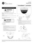
Wires in the wiring box (Figure 2). See Diagram A for wiring
schematic.
POLARITY MUST BE PROPERLY APPLIED
(VIOLET + To control +) AND (GRAY – To control -)
Shorting (example with a switch) the violet and gray wires will
cause the Nuvation to operate at low wattage, removing the short
will cause the lamp to operate at full wattage.
External control systems can be used to operate the bi-level
function.
A zero (0) to ten (10) volt DC power supply can control the bi-level
operation.
This can be either to continuously adjustment lamp wattage 50%
to 100 %.
Or one step 50% to 100%.
DC Control Voltage
Output Level
0V
50%
+5V
75%
Diagram A
Added Features of the GELS NUVATION™
• Automatic lamp shut off if the lamp fails to start within 90
minutes
• After a power shut off the NUVATION must be switched off and
then back on (cycle time 1 to 2 seconds).
• Automatic lamp shut off for end of life high voltage lamps
FINAL ASSEMBLY
LIGHT DISTRIBUTION ADJUSTMENT: FGE, DGE, OGE
The Optical Assembly is provided with an adjustable Socket
Holder for changing spacing criteria. Position is preset at factory
to meet specified spacing criteria. If it is necessary to adjust
Socket, consult photometric tables given in the catalog. Loosen
3 Clip Screws to allow Socket Holder to rotate freely. Desired
position is selected by aligning step designation with clips. Rotate
Clips back to their original position and retighten screws.
OPTICAL ASSEMBLY/MOUNTING
FGE, DGE, LME, OGE, VSE
NOTE: Wet Location units are provided with a sponge rubber
Gasket (in bag attached to ballast housing) that must be slipped
over electrical plug prongs of optical assembly before final
assembly.
1. (Figure 6) Slide Reflector to bottom of Ballast Housing.
1a. On VSE units with Safety Chains, orient the reflector
so that the Ballast Housing and Reflector Safety
Chain Attachment Holes are on the same side.
1b. On VSE units push the Reflector Mounting Bracket
thru the reflector opening and slide it over the Socket
Brackets all the way. On 400 watt Metal Halide units
the top (first) hole of the Mounting Bracket will snap
over the Socket Bracket screws. On all others, the
bottom (second) hole will snap over the bracket
screws (Figure 7). For additional assembly instructions, refer to the instruction sheet that came
in the small box with the metal reflector and
-mounting bracket.
SOCKET
+10V
100%
POLARITY MUST BE PROPERLY APPLIED
(VIOLET + To control +) AND (GRAY – To control -)
A resistor or potentiometer (pot) can also be used to continuously
adjust lamp wattage by connecting to the VIOLET + and GRAY –
wires. The resistor or potentiometer should be in the 0 – 50K ohm
range. The voltage output from the VIOLET + and GRAY – wires will
be in the 0-10 volt range and current will be less than one (1)
milliamp.
LOCKING
TABS
Figure 6
Figure 7
SOCKET
QUARTZ
SOCKET
LOCKING
TABS
Figure 8
NOTE: If VSE unit has a safety light option, clip Quartz Socket
over Socket Bracket leg and reflector bracket leg in a horizontal
position (see Figure 8).