1
FUJI UGx20 SERIES PROGRAMMABLE OPERATION DISPLAY
USER'S MANUAL <HARDWARE>
TYPE: UG520H-x
UG420H-x
UG320H-x
UG221H-x
UG220H-x
FEH352c
Preface
UG Series
Thank you for selecting the Fuji Programmable Operation Display, POD UG520/420/
320/221/220 Series (called as the UG20 or POD, hereafter).
For proper set-up, you are requested to read through this booklet to understand more
about the product.
For more information about UG20 series, refer to the Reference Manual.
For further details about the PLC, see the manual attached to each PLC.
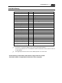
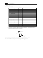
[Reference]
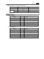
In addition to this manual, the following manuals on the UG20 Series are available.
Please ask your nearest dealer for the appropriate manuals and read them as required.
Name
Manual No.
FEH375
Contents
UG Series Manual
<Operation>
UG Series Manual
<Function>
UG Series Manual
<CC-Link Communications>
UG Series Manual
<T-Link Communications>
UG Series Manual
<SX-BUS Communications>
UG Series Manual
<OPCN-1 Communications>
UG Series Manual
<Variable
Name Cooperation Function>
FEH363
Describes how to operate screen editor
(UG00S-CW) for the UG Series.
Describes the functions of the UG
Series.
Describes the procedures for communication
with PLCs using the optional CC-Link interface.
Describes the procedures for communication
with PLCs using the optional T-Link interface.
Describes the procedures for communication
with PLCs using the optional SX-Bus interface.
Describes the procedures forcommunication
with PLCs using the optional OPCN-1 interface.
Describes the variable name cooperation function
to be used between the UG editor and D300win.
UG Series Manual
<Ethernet Communications>
FEH366
Describes the procedures for communicating
via the optional ETHERNET interface.
UG Series Manual
<FL-Net Communications>
FEH367
Describes the procedures for communicating
via the optional FL-Net interface.
UG Series Manual
<PROFIBUS Communications>
FEH368
Describes the procedures for communicating
via the optional PROFIBUS interface.
UG Series Manual
<Ladder
Monitor Specifications>
FEH379
The Functions and instructions of the Ladder
Monitor are explained.
FEH376
FEH355
FEH356
FEH357
FEH358
[Notes]
(1)This manual may not, in whole or in part, be printed or reproduced without the prior written consent
of Fuji Electric Co., Ltd.
(2)Information in this manual is subject to change without prior notice.
(3)Windows and Excel are registered trademarks of Microsoft Corporation in the United States and other
countries.
(4)All other company names or product names are trademarks or registered trademarks of their respective holders.
(5)This manual is intended to give accurate information about POD hardware. If you have any questions, please contact your local distributor.
Notes on Safe Use of POD
In this manual, you will find various notes categorized under the following levels with
the signal words "DANGER," and "CAUTION."
DANGER
CAUTION
Indicates an imminently hazardous situation which, if not avoided,
will result in death or serious injury.
Indicates a potentially hazardous situation which, if not avoided, may
result in minor or moderate injury and could cause property damage.
Note that there is a possibility that the item listed with
CAUTION may have serious
ramifications.
DANGER
• Never use the input function of POD for operations that may threaten human life or to damage
the system, such as switches to be used in case of emergency. Please design the system so
that it can cope with malfunction of a touch switch.
• Turn off the power supply when you set up the unit, connect cables or perform maintenance
and inspection. Failure to do so could cause an electric shock or damage to the unit.
• You must put a cover on the terminals on the unit when you turn the power on and operate
the unit. Without the terminal cover in place, an electric shock may occur.
• The liquid crystal in the LCD panel is a hazardous substance. If the LCD panel is damaged,
never swallow the leaked liquid crystal. If the liquid crystal spills on your skin or clothing, use
soap and wash off thoroughly.
Notes on Safe Use of POD
CAUTION
[Notes on System Design]
• Never bundle control cables and input/output cables with high-voltage and large-current
carrying cables such as power supply cables. Keep these cables at least 200 mm away from
the power supply or high-voltage cables. Otherwise, malfunction may occur due to noise.
• For use in a nuclear energy facility, or other facility of such official importance, please consult
your local distributor.
[Notes on Installation]
• Operate (or store) POD under the conditions indicated in this manual and related manuals.
Failure to do so could cause fire, malfunction, physical damage or deterioration.
• Understand the following environmental limits for use and storage of POD. Otherwise, fire or
damage to the unit may result.
-Avoid locations where there is a possibility that water, corrosive gas, flammable gas,
solvents, grinding fluids or cutting oil can come into contact with the unit.
-Avoid high temperature, high humidity, and outside weather conditions, such as wind, rain
or direct sunlight.
-Avoid locations where excessive dust, salt, and metallic particles are present.
-Avoid installing the unit in a location where vibration or physical shock may be transmitted.
• Equipment must be correctly mounted so that the main terminal of POD will not be touched
inadvertently.
• Tighten the POD mounting screws to the specified torque. Excessive tightening may distort the
panel surface. Loose tightening may cause POD to come off, malfunction or be short-circuited.
• Tighten terminal screws on the power input terminal block equally to a torque of 0.5 Nom.
• Check the appearance of POD when it is unpacked. Do not use the unit if any damage or
deformation is found.
• POD has a glass screen. Do not drop or give physical shock to the unit.
[Notes on Cable Connection]
• Connect the cables correctly to the terminals of POD in accordance with the specified voltage
and wattage. Over-voltage, over-wattage or incorrect cable connection could cause fire,
malfunction or damage to the unit.
• Be sure to establish a ground of POD. The FG terminal must be used exclusively for the unit
with the level of grounding resistance less than 100W.
• Prevent any conductive particles from entering into POD. Failure to do so may lead to fire,
damage or malfunction.
Notes on Safe Use of POD
CAUTION
[Notes on Maintenance and Operation]
• Fuji Electric Co., Ltd. is not responsible for any damages resulting from repair, overhaul or
modification of POD that was performed by an unauthorized person.
• Do not use thinners for cleaning because they may discolor the POD surface. Use alcohol or
benzine commercially available.
• Do not use a sharp-pointed tool when pressing a touch switch.
• Only experts are authorized to set up the unit, connect the cables or perform maintenance
and inspection.
• If a data receive error occurs when POD and the counterpart (PLC, temperature controller,
etc.) are started at the same time, read the manual for the counterpart unit and handle the
error correctly.
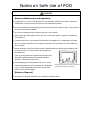
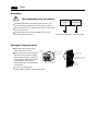
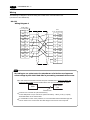
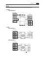
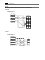
• Switch resolution of the POD UG20 series is determined by the analog-type resistance film.
Do not press two or more positions on the screen at
the same time.
If two or more positions are pressed at the same time,
SYSTEM
F1
F2
F3
the switch located between the pressed positions
activates. Please take note of this.
F4
F5
SWITCH
F7
POWER
• Avoid displaying the same patterns for hours. It may
cause afterimages due to the property of LCD display.
If you use the fixed patterns for hours, use the autoOFF function of the backlight.
F6
Pressing two positions at the same time
activates the swith in the center.
[Notes on Disposal]
• At the time of disposal, POD must be treated as industrial waste.
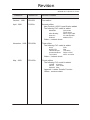
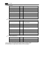
Revision
*Manual No. is shown on cover.
*Manual No.
Revision contents
October , 1999
FEH352
First edition
April , 2001
FH352a
Second edition
New Product (UG221) specification added.
The following PLC model is added.
Printed on
Mitsubishi
Allen-Bradley
Siemens
Modicon
QnH series
FX1S series
Micro Logix 1000
S7-300/400 MPI
Modbus RTU
Others , contents check
November , 2002
FEH352b
Third edition
The following PLC model is added.
SAIA
MOELLER
Telemecanique
Automationdirect
Toyo Denki
PCD
PS4
TSX Micro
Direct LOGIC
uGPC sx series
Others , contents check
May , 2003
FEH352c
Fourth edition
The following PLC model is added.
VIGOR M series
DELTA
DVP series
BADOR Mint
Appendix : Ladder Transfer Function
Others , contents check
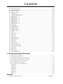
Contents
Preface
Notes on Safe Use of POD
Revision
1. Hardware Specifications
1. Special Features .......................................................................................................... 1-1
2. Notes on Usage ............................................................................................................ 1-2
3. System Composition .................................................................................................... 1-4
4. Names of Components ................................................................................................ 1-11
5. Dimensions and Panel Cut-out ................................................................................... 1-13
6. Mounting Procedure ................................................................................................... 1-18
7. Wiring ........................................................................................................................ 1-19
8. Specifications ............................................................................................................. 1-21
9. Serial Connector (CN1) ............................................................................................... 1-27
10. Setting of Dip Switches .............................................................................................. 1-29
11. Modular Jack 1 & 2 ................................................................................................... 1-30
12. Bar Code Reader Interface .......................................................................................... 1-31
13. Printer Interface (CN2) ............................................................................................... 1-32
14. Video Interface ........................................................................................................... 1-33
15. Analog RGB Input ...................................................................................................... 1-34
16. Connection ................................................................................................................ 1-37
17. Operation of POD Main Menu ..................................................................................... 1-42
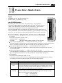
18. Function Switches ...................................................................................................... 1-59
2. Connection to Link Units
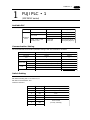
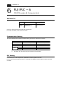
1. FUJI PLC • 1 ................................................................................................................ 2-1
2. FUJI PLC • 2 ................................................................................................................ 2-4
3. FUJI PLC • 3 ................................................................................................................ 2-6
4. FUJI PLC • 4 ................................................................................................................ 2-8
5. FUJI PLC • 5 .............................................................................................................. 2-11
6. FUJI PLC • 6 .............................................................................................................. 2-14
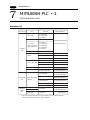
7. MITSUBISHI PLC • 1 .................................................................................................. 2-16
8. MITSUBISHI PLC • 2 .................................................................................................. 2-22
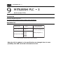
9. MITSUBISHI PLC • 3 .................................................................................................. 2-26
10. MITSUBISHI PLC • 4 .................................................................................................. 2-28
11. MITSUBISHI PLC • 5 .................................................................................................. 2-32
12. MITSUBISHI PLC • 6 .................................................................................................. 2-35
13. OMRON PLC • 1 ......................................................................................................... 2-37
14. OMRON PLC • 2 ......................................................................................................... 2-42
15. Sharp PLC • 1 ............................................................................................................ 2-43
16. Sharp PLC • 2 ............................................................................................................ 2-46
17. HITACHI PLC • 1 ........................................................................................................ 2-48
18. HITACHI PLC • 2 ........................................................................................................ 2-51
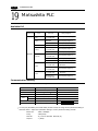
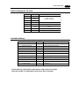
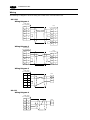
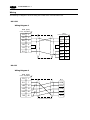
19. Matsushita PLC ......................................................................................................... 2-54
20. YOKOGAWA PLC • 1 ................................................................................................... 2-57
21. YOKOGAWA PLC • 2 ................................................................................................... 2-59
22. YASKAWA PLC • 1 ...................................................................................................... 2-62
23. YASKAWA PLC • 2 ...................................................................................................... 2-65
24. TOYOPUC PLC ........................................................................................................... 2-67
25. Koyo PLC ................................................................................................................... 2-70
Contents
26. Allen-Bradley PLC • 1 ................................................................................................. 2-75
27. Allen-Bradley PLC • 2 ................................................................................................. 2-80
28. GE Fanuc PLC • 1 ...................................................................................................... 2-84
29. GE Fanuc PLC • 2 ...................................................................................................... 2-86
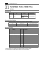
30. TOSHIBA PLC ............................................................................................................ 2-88
31. TOSHIBA MACHINE PLC ............................................................................................ 2-90
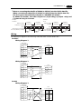
32. SIEMENS PLC • 1 ...................................................................................................... 2-92
33. SIEMENS PLC • 2 ...................................................................................................... 2-94
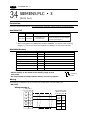
34. SIEMENS PLC • 3 ...................................................................................................... 2-96
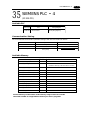
35. SIEMENS PLC • 4 ...................................................................................................... 2-97
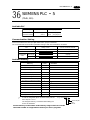
36. SIEMENS PLC • 5 ...................................................................................................... 2-99
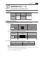
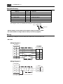
37. SIEMENS PLC • 6 .................................................................................................... 2-101
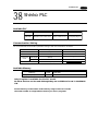
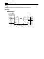
38. Shinko PLC .............................................................................................................. 2-103
39. SAMSUNG PLC ........................................................................................................ 2-105
40. KEYENCE PLC • 1 .................................................................................................... 2-107
41. KEYENCE PLC • 2 .................................................................................................... 2-109
42. KEYENCE PLC • 3 .................................................................................................... 2-112
43. LG PLC .................................................................................................................... 2-114
44. FANUC PLC .............................................................................................................. 2-119
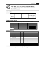
45. FATEK PLC .............................................................................................................. 2-121
46. IDEC PLC ................................................................................................................. 2-123
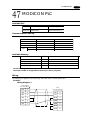
47. MODICON PLC ......................................................................................................... 2-125
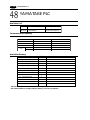
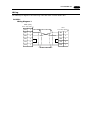
48. YAMATAKE PLC ....................................................................................................... 2-126
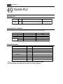
49. TAIAN PLC ............................................................................................................... 2-128
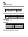
50. SAIA PLC ................................................................................................................. 2-130
51. MOELLER PLC ......................................................................................................... 2-132
52. Telemecanique PLC .................................................................................................. 2-133
53. Automationdirect PLC .............................................................................................. 2-134
54. VIGOR PLC .............................................................................................................. 2-137
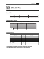
55. DELTA PLC .............................................................................................................. 2-139
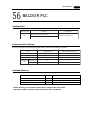
56. BALDOR PLC ........................................................................................................... 2-141
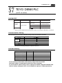
57. TOYO DENKI PLC .................................................................................................... 2-143
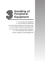
3. Handling of Peripheral Equipment
1.
2.
3.
4.
5.
6.
7.
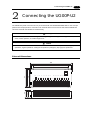
Connecting the UG00P-U1 ............................................................................................. 3-1
Connecting the UG00P-U2 ............................................................................................. 3-3
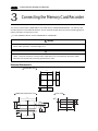
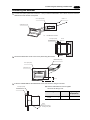
Connecting the Memory Card Recorder .......................................................................... 3-6
Connecting the Memory Extension Unit ......................................................................... 3-9
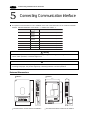
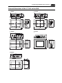
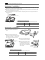
Connecting Communication Interface .......................................................................... 3-12
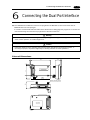
Connecting Dual Port Interface .................................................................................... 3-15
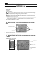
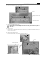
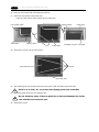
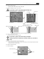
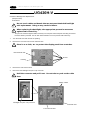
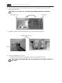
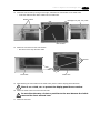
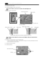
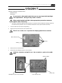
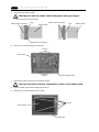
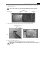
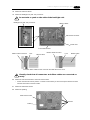
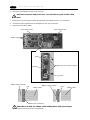
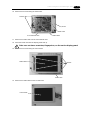
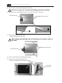
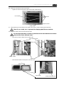
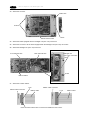
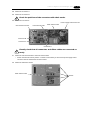
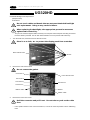
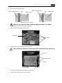
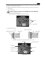
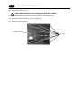
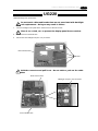
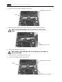
How to Replace the Backlight Unit ............................................................................... 3-19
UG520H-V ................................................................................................................. 3-20
UG420H-V ................................................................................................................. 3-26
UG420H-T ................................................................................................................. 3-31
UG420H-S ................................................................................................................. 3-36
UG320 ....................................................................................................................... 3-41
UG320HD .................................................................................................................. 3-48
UG220 ....................................................................................................................... 3-53
Appendix
Ladder Transfer Function ..................................................................................... Appendix-1
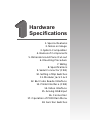
Hardware
Specifications
1. Special Features
2. Notes on Usage
3. System Composition
4. Names of Components
5. Dimensions and Panel Cut-out
6. Mounting Procedure
7. Wiring
8. Specifications
9. Serial Connector (CN1)
10. Setting of Dip Switches
11. Modular Jack 1 & 2
12. Bar Code Reader Interface
13. Printer Interface (CN2)
14. Video Interface
15. Analog RGB Input
16. Connection
17. Operation of POD Main Menu
18. Function Switches
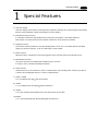
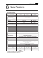
1 Special Features
1
1-1
Special Features
1) 128-color Display
128-color display which makes colorful expression possible is realized. Not only drawings but also bitmap
files are clearly displayed. (UG221 and UG220 is 16-color display.)
2) Data Sheet Printing Function
It is possible to make the original data sheet screen by the panel editor (= the editing software).
Daily reports or monthly reports that the operator must fill out can be printed in an instant.
3) Sampling Function
This function makes it possible to store the sampling data in an IC card. The stored data can be edited
easily by a personal computer. It can be used widely in various fields.
4) Macro Function
With this function, UGx20 series can make programs which previously had to be produced by PLC.
5) Multi Window Function
Up to three windows can be displayed simultaneously on a screen.
It is easy to move or delete the displayed windows.
6) Video Function
UGx20 series can be connected to a video or a CCD camera, and the image which is taken by a video or
a camera can be displayed directly in a screen of UGx20 series.
7) UG221, UG220
A 5.7 inch display with 320
240 dot resolution.
8) UG320
A 7.7 inch display with VGA (640
480 dot resolution).
9) UG420
A 10.4 inch standard model display which uses the previous screen data.
10) UG520
A 12.1 inch large display with SVGA (800
600 dot resolution).
1-2
2
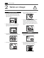
2 Notes on Usage
Notes on Usage
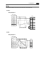
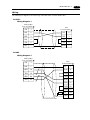
Environmental Limits
1. Use POD at an ambient temperature of 0 to
50ºC, and a relative humidity of 35-85 %RH.
(But, a UG420 STN multi-color display can be
used at 0 to 40ºC.)
5. Never install POD in a place where impacts or
vibrations may be transmitted.
0 to 50°C
50
40
30
20
10
0
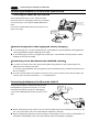
2. Install a forced fan or an air conditioner to
maintain the ambient temperature when it is
higher than the above mentioned range.
6. Avoid any place in which there is the possibility
that water, corrosive gas, flammable gas,
solvents or coolants, grinding oil can come in
contact with the unit. Never install the unit in a
place where dust, salt and metallic particles are
present.
Fan
YOUZAI
Vent
Locations
3. Avoid places where moisture may easily
condense due to sudden temperature changes.
1. Secure sufficient space around POD for
ventilation.
4. Avoid direct sunlight.
2. Never attach POD to the top of any apparatus
generating high levels of heat (heater,
ransformer, large-capacity resistor, etc.).
2 Notes on Usage
3. Never install POD in the same compartment as
high-voltage equipment. The unit should be at
least 200 mm away from high-voltage lines or
power cables.
1-3
4. Securely fasten and lock every connector for
each cable. Double-check this before turning the
power on.
k!
Loc
Usage
1. An emergency stop circuit must be composed of
an external relay circuit with a start signal for
POD built in. Do not create switches on POD to
be used in case of emergency.
5. In a dry environment, POD may generate a large
amount of static electricity.
Therefore, before touching the unit, touch a
grounded metallic section to discharge the static
electricity.
6. Application of thinner may discolor POD. Use
alcohol or benzine available commercially for
cleaning.
Switch to be used
in emergency
Emergency
Stop
Alcohol
2. POD has a glass screen. Never drop or subject
the unit to strong impacts.
3. Tighten mounting screws with the following
torques.
Screw
Screw Size
Torque (N•m)
UG320/220
M3
0.3 to 0.5
UG221
M4
0.3 to 0.5
UG520/420
M4
0.5 to 0.7
Type
Note :Never fasten these screws too tightly,
otherwise the cover of POD may be deformed.
BENZINE
7. Never remove any printed circuit board from
POD. (This will harm the unit.)
8. Never operate the display by using a tool with a
sharp point like a screwdriver.
Touch the display by fingers.
3 System Composition
1-4
3
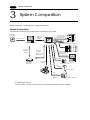
System Composition
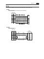
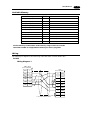
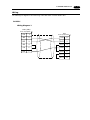
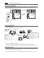
System Composition / Model Indication / Peripheral Equipment
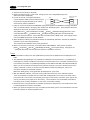
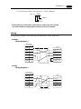
System Composition
The following illustration shows possible system configurations using UG20.
Panel Editor
for UG series
During operation
(Link communication)
RS-232C/RS-422
Transferring
screen data
UG00C-T
Creating screens
run
stop
• • •
• • •
• • •
• • •
• • •
• • •
• • •
• • •
• • •
• • •
• • •
• • •
• • •
• • •
• • •
• • •
UG03I-x
Link Unit
During operation
(TLink/OPCN-1/SXBus/ProfiBus/Ethernet)
UG00S-CW
Personal Computer (PC)
Transferring
screen data
UG00C-T
UGx20
Transferring
screen data
or
Memory manager
/Data logging
During operation
(Universal serial
communication)
RS-232C/RS-422
Exclusive Cable
Card Recorder
UG00P-MR *1
Printer Cable
*2
UG00C-C
Universal-purpose
computer
Video / CCD camera
Cable
UG00C-B
Bar Code Reader
Printer
Cable
UG00C-H
PV
SV
or
UG00C-B
*1
*2
○ AT
○ OUT1
S ET
R/S
○ OUT2
○ ALM1
○ ALM2
Temperature Controller
UG00P-MR is optional.
The interface for video function (using only in UG520 and UG420) is optional for Maker.
3 System Composition
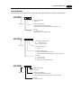
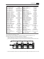
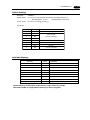
List of Models
The characters on the right of model names represent optional features and special specifications.
UG220H Power requirements
4 : 24V DC
Main unit
Interface specifications
C : Serial (Link Unit Communication)
(Other interfaces can be supported using the I/F unit.)
LCD type
S : STN color LCD
L : Monochrome LCD (White mode)
UG221H Touch Panel Specifications
D
: Matrix sw type
None : Analog sw type
Main unit
Power requirements
4 : 24V DC
Interface specifications
C : Serial (Link Unit Communication)
(Other interfaces can be supported using the I/F unit.)
LCD type
T : TFT color LCD
S : STN color LCD
L : Monochrome LCD (Blue mode)
UG320H Power requirements
4 : 24V DC
Main unit
Interface specifications
C : Serial (Link Unit Communication)
(Other interfaces can be supported using the I/F unit.)
LCD type
S : STN color LCD
1-5
1-6
3 System Composition
UG420H Main unit
Image input
NONE
1 : Video interface (TFT color LCD Only)
2 : RGB interface (TFT VGA only)
Memory card
None : Standard (Outside recorder)
M : Memory card interface
Power requirements
1 : 100 to 200V AC
4 : 24V DC
Interface specifications
C : Serial (Link Unit Communication)
(Other interfaces can be supported using the I/F unit.)
LCD type
S : STN color LCD
T : TFT color LCD VGA
V : TFT color LCD SVGA
UG520H Image input
NONE
1 : Video interface (TFT color LCD Only)
Main unit
Memory card
None : Standard (Outside recorder)
M : Memory card interface
Power requirements
1 : 100 to 200V AC
4 : 24V DC
Interface specifications
C : Serial (Link Unit Communication)
(Other interfaces can be supported using the I/F unit.)
LCD type
V : TFT color LCD SVGA
E.g. :
UG220H-LC4 (Monochrome LCD / Serial / 24V DC)
UG320H-SC4 (STN color LCD / Serial / 24V DC)
UG420H-TC1M1 (TFT color LCD VGA / Serial /100 to 200V AC / Memory card interface / Video interface)
UG520H-VC41 (TFT color LCD SVGA / Serial / 24V DC / Standard / Video interface)
Products conforming to overseas standards
For the products that conform to overseas standards, such as CE marking, please contact Fuji Sales
Department.
3 System Composition
1-7
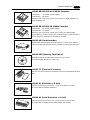
List of Options
Type
Optional
by Manufacturer
Item
Card Interface
UG221
UG320
UG420H-S UG420H-T UG420H-V UG520H-V
Video Interface
Analog RGB Input
Interface
Extension I/O Unit : UG00P-U1
*2
(16 inputs / 16 outputs)
Serial Extension I/O : UG00P-U2
(16 inputs / 16 outputs)
*2
Extension Memory
Cassette: (4Mbyte)
Optional by User
UG220
*1
SRAM Cassette
: (512Kbyte)
UG00P-D4
UG221P-D4
UG00P-SR
UG221P-SR
Communication Interface Unit
: UG03I-S/J/T/C/E/P
Communication Interface Unit
: UG02I-S/J/T
Card Recorder
: UG00P-MR
*3
*3
*1
Terminal Converter
: UG00P-TC
*1
*2
*3
Prepare for UGx20 with card interface, or UGx20 and UG00P-MR (card recorder).
UG00P-U1 : Rear-side installation I/O unit, UG00P-U2 : Panel-side installation I/O unit
UG03I-T/UG02I-T : T-LINK, UG03I-J/UG02I-J : OPCN-1, UG03I-S/UG02I-S : SX BUS,
UG03I-C : CC-LINK, UG03I-E(2) : Ethernet or FL-net, UG03I-P : PROFIBUS
Memory Card
A SRAM card or FPROM card can be used for the memory card. The following table shows the
difference between the SRAM card and FPROM card:
SRAM
FROM
Supports the functions of POD memory manager and
data logging, and transmission of screen data.
Supports transmission of screen data.
Data is partially readable and writable at any time.
Data is written and read all together. Data cannot be
written or read partially.
Contains a battery. Replace the battery when it runs
out.
No battery replacement is required.
*
The FROM card cannot support any functions of memory manager and data logging.
The following memory cards supplied from Fuji Electric Co., Ltd. are recommended.
SRAM
UG00K-S25K(256K)
UG00K-S02M(2M)
UG00K-S51K(512K)
UG00K-S04M(4M)
UG00K-S01M(1M)
FROM
UG00K-F25K(256K)
UG00K-F01M(1M)
UG00K-F51K(512K)
UG00K-F02M(2M)
1-8
3 System Composition
Model Indication
UG221, UG220
Display area : 115.2
(A 5.7 inch display.)
86.4 mm
UG320
Display area : 157.4
(A 7.7 inch display.)
118.1 mm
UG420
Display area : 211.2
(A 10.4 inch display.)
158.4 mm
UG520
Display area : 246.0
(A 12.1 inch display.)
184.5 mm
Peripheral Equipment
The following options are available for using UGx20 series more effectively.
UG00S-CWV3
(Panel Editor for Windows98/NT4.0/Me/2000/XP)
Application software for editing display data for UG series.
UG00C-T (Data Transfer Cable) 3m
Connects UGx20 to a personal computer, or a personal computer to
UG00P-MR.
UG00C-C (Printer Cable) 2.5m
Connects UGx20 to a printer.
3 System Composition
1-9
F
R
O
M
1
• UG00P-D4
: for UG520, UG420, UG320
• UG221P-D4 : for UG221
Extension print circuit board to extend the memory for display data back-up.
There is 4Mbyte type.
J
P
1
C
N
1
F
R
O
M
0
UG00P-D4•UG221P-D4 (FPROM Cassette)
P
0
2
1
7
2
-2
C
N
1
UG00P-SR•UG221P-SR (SRAM Cassette)
SANYO
JAP
AN
+
CR2430
TS
M n O 2-
Li
CELL
3 VO
L
• UG00P-SR : for UG520, UG420, UG320
• UG221P-SR : for UG221
Extension print circuit board to back-up the memory for sampling data,
Internal Memory and Memo Pad. There is 512kbyte type. It is also possible to
set the calendar for displaying in UGx20 at this cassette.
UG00P-MR (Card Recorder)
Reads display data created by personal computer, or works as an external
memory storage system for the memory manager and data logging functions.
UG00P-MSE (Memory Card Editor)
Application software for editing data stored in a memory card.
( For Windows 98 / Me / NT 4.0 / 2000 / XP )
UG00P-TC (Terminal Converter)
CN
1
Used for connection between a UGx20 and a PLC at the RS-422/485 terminal
block.
SW
1
TB
1
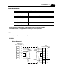
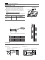
UG00P-U1 (Extension I/O Unit)
Used as an external I/O unit for PLC. It has 16 inputs and 16 outputs.
(It can be used for UG520 and UG420.)
UG00P-U2 (Serial Extension I/O Unit)
DC24V
IN1
FG
IN0
IN2
IN3
IN4
IN5
IN6
IN7
IN8
MJ1
IN9
IN10
IN11
IN12
IN13
IN14
IN15
OUT1
COM+
OUT0
OUT2
OUT3
OUT4
OUT5
OUT6
OUT7
COM1
OUT8
OUT9
OUT10
OUT11
OUT12
OUT13
OUT14
OUT15
COM2
Used as an external I/O unit for PLC. It has 16 inputs and 16 outputs.
(It can be used for UG520,UG420,UG320,UG221 and UG220.)
3 System Composition
1 - 10
UG03I-x [x:T T-Link, x:J OPCN-1, x:S SX BUS,
x:E(2) Ethernet•FL-net, x:C CC-Link,
x:P PROFIBUS] (Communication Interface Unit)
Used to communicate with each network.
It makes it possible to connect multiple UGx20 series to a PLC. This system,
which enables other devices to connect to the same network, brings about
the reduction in costs of the whole system.
UG02I-x
[x:T T LINK, x:J OPCN-1, x:S
(Communication Interface Unit)
SX BUS]
Used for UG220 to communicate with each network.
G
P
P
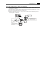
UG00P-DI (ACPU/QnACPU/FXCPU Dual Port Interface)
GD
Add-on connector with two ports, specifically designed for the connector on
the MITSUBISHI’s ACPU/QnACPU/FXCPU programmer. This can improve
operability of the ACPU/QnACPU/FXCPU programmer that is directly
connected.
UGx20P-PS
[x:2 UG220,UG221 , 3 UG320 , 4
5 UG520] (Protection Sheet)
UG420,
Protects the operation panel surface. Five sheets are included in one
package.
UG00C-B (bar-code reader (temperature controller)
connecting cable) 3 m
Used to connect a bar-code reader to the POD.
Also used to connect a temperature controller to the POD via RS-232C.
UG00C-H (Multi-link 2 (temperature controller)
connecting cable) 3 m
Used to connect between POD master and POD slave for Multi-link 2
connection.
Also used to connect a temperature controller to the POD via RS-485.POD
slave station in the Multi-Link 2 connection.
UGxxP-Bx [UG220P/320P/420P/520P-Bx]
(Backlight for Replacement)
Placement backlight parts for UGx20 series.
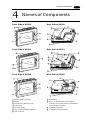
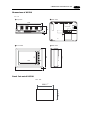
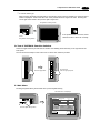
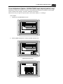
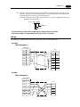
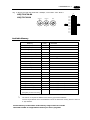
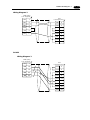
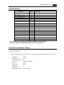
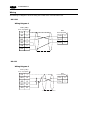
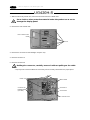
4 Names of Components
4
1 - 11
Names of Components
Front Side of UG220
Rear Side of UG220
10
1
13
DC24V
3
(+)
(-)
5
CN2
4
MJ2
CN1
8
MJ1
9
7
2
1
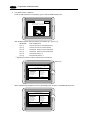
Front Side of UG221
Rear Side of UG221
10
1
8
24VDC
9
3
11
5
MJ2
7
MJ1
CN1
CN2
2
6
4
1
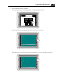
Front Side of UG320
Rear Side of UG320
10
1
13
5
(+)
DC24V
(-)
MJ2
MJ1
4
CN1
3
8
9
CN2
11
7
2
1
1
Mounting holes for fixtures
8
2
9
6
Display
Function keys (Refer to P1-59)
Power lamp
DC power supply
CN1: for PLC (RS-232C, RS-422)
7
CN2: for printer
3
4
5
10
11
Dip switches
MJ1, 2: for data transfer, for temperature
controller, for bar-code reader, for UG00P-MR
and for UG00P-U2 (option)
for UG00P-D4 (option)
for UG03I-S/J/T/C/E/P (option)
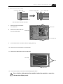
1 - 12
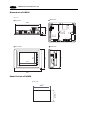
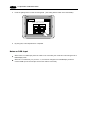
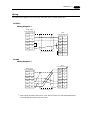
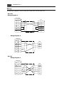
4 Names of Components
Front Side of UG420
Rear Side of UG420
1
6
11
L
100240VAC
N
NC
3
12
15
13
CN1
8
MJ2
MJ1
14
CN2
7
2
1
10
9
4
Front Side of UG520
Rear Side of UG520
1
11
6
L
100240VAC
N
NC
12
15
13
CN1
8
MJ2
MJ1
14
CN2
7
2
1
9
10
3
4
1
2
3
4
5
6
7
8
Mounting holes for fixtures
Display
Function keys (Refer to P1-59)
Power lamp
AC power supply / DC power supply
CN1: for PLC (RS-232C, RS-422)
CN2: for printer
Dip switches
9
MJ1, 2: for data transfer, for temperature
controller, for bar-code reader, for UG00P-MR
and for UG00P-U2 (option)
10
for UG00P-D2/D4 (option)
for video (option)
for UG03I-S/J/T/C/E/P (option)
11
12
13
14
for UG00P-U1 (option)
Card interface (option)
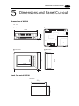
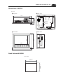
5 Dimensions and Panel Cut-out
5
1 - 13
Dimensions and Panel Cut-out
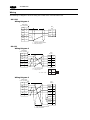
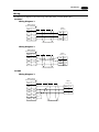
Dimensions of UG220
Unit : mm
Rear View
Top View
5
45
173.6
CN1
CN2
MJ2
Side View
130.8
88.4
138.8
Front View
MJ1
117.2
182.5
Panel Cut-out of UG220
Unit : mm
+0.5
-0
131 +0.5
-0
174
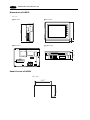
5 Dimensions and Panel Cut-out
1 - 14
Dimensions of UG221
Unit : mm
Side View
Front View
SYSTEM
F1
F3
POWER
138.8
130.8
F2
F4
F5
182.5
Under View
6
Rear View
+
24V DC
4
47.3
-
Do not remove this seal.
unless the optional unit is mounted.
MJ2
MJ1
CN2
CN1
Panel Cut-out of UG221
Unit : mm
174 +
131 +-00.5
0.5
-0
5 Dimensions and Panel Cut-out
1 - 15
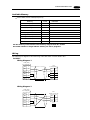
Dimensions of UG320
Unit : mm
Top View
Rear View
220
TB1
(+)
DC 24V
60.1
( )
CN1
6
MJ2
CN2
Front View
165
175
121
Side View
160
230
Panel Cut-out of UG320
Unit : mm
+0.5
-0
+0.5
-0
165.5
220.5
MJ1
1 - 16
5 Dimensions and Panel Cut-out
Dimensions of UG420
Unit : mm
Rear View
Top View
288
L
100240VAC
N
CN1
16
76.3
NC
MJ2
CN2
Front View
215.2
240
158
Side View
211
310
Panel Cut-out of UG420
Unit : mm
+0.5
-0
+0.5
-0
216.2
289
MJ1
5 Dimensions and Panel Cut-out
1 - 17
Dimensions of UG520
Unit : mm
Top View
Rear View
312
L
100240VAC
NC
CN1
16
79.8
N
MJ2
CN2
Side View
245.2
270
185
Front View
247
334
Panel Cut-out of UG520
Unit : mm
+0.5
-0
+0.5
-0
246.2
313
MJ1
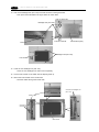
6 Mounting Procedure
1 - 18
6
Mounting Procedure
Mounting Procedure
1
Cut out the mounting panel (Max. thick: 3.2 mm) to match the dimensions shown below.
Mounting panel
Unit : mm
174
220.5
+0.5
-0
+0.5
-0
Cut-out
UG320
+0.5
-0
313
+0.5
-0
246.2
216.2
+0.5
-0
+0.5
-0
165.5 -+0.5
0
UG420
2
165.5
+0.5
-0
UG220
UG221
289
+0.5
-0
+0.5
-0
131
220.5
UG520
Insert the fixtures attached to UGx20 into the mounting holes on UGx20. Tighten them with the locking
screws. (Number of the fixtures: all series 4 pcs,)
Fixture
Dimensions of Fixtures
Mounting panel
(Unit : mm)
20
Mounting hole
10.5
.0
Mounting hole
17.8
for UG220/320
TB1
UGx20
(+)
DC 24V
(-)
MJ2
30
MJ1
10.5
.0
17.8
for UG221/420/520
3
torque:
UG320/UG221/UG220
0.3 to 0.5 N • m
UG520/UG420
0.5 to 0.7 N • m
The waterproof packing mounted on the UG221 main unit shall come in close contact with the mounting
panel so that it is surely caught between the mounting panel and UG221.
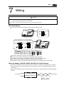
7 Wiring
7
1 - 19
Wiring
Caution
•
•
Do not remove the dust-proof seal till you finish wiring in the panel. If the seal is removed, conductor chips or other
foreign matter may enter the device to cause failure.
When you finished wiring in the panel, be sure to remove the dust-proof seal.
Electrical Wiring
Connects the cable for power supply to TB1 on the rear side of UGx20.
DC24V
MJ2
TB1
(+)
(-)
MJ1
Power supply
24V ±10% DC
CN1
(+ )
24V DC
(-)
CN2
Earth
UG320/UG221/UG220
Type : 100-200V AC
Type : 24V DC
L
100240VAC
N
NC
TB1
TB1
+
L
Power supply
24V ±10% DC
24VDC
CN1
Power supply
100-200VAC
-
N
MJ2
NC
NC
MJ1
CN2
Earth
Earth
UG520/UG420
Type
Screw Screw Size
UG320/UG221/UG220
UG520/UG420
Torque (N • m)
Clamp Terminal (Unit : mm)
M3.5
0.5
7.0MAX
7.0MAX
M3.5
0.5
8.0MAX
8.0MAX
When TB1 is used for wiring, refer to the following table.
The power source used must be within the allowable voltage fluctuation.
Use a power source with low noise between the cables or ground and the cable.
Use as thick a power cable as possible to minimize any drop in voltage.
Keep cables of 100V AC and 24V DC sufficiently away from high-voltage, large-current cables.
Notes on Usage of UG520/UG420 100-200V AC Specifications
Generally, an isolating transformer improves noise resistance. However, if the display unit is far away
from the secondary port of the transformer and noise gets mixed in, an isolating transformer becomes
unnecessary.
If any power voltage fluctuation caused by noise is expected, it is recommended that a voltage stabilizer
be used.
Power Supply
Insulation transformer
or
Stabilized transformer
to UG520/UG420
1.25mm
2
twisted
1 - 20
7 Wiring
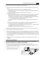
Grounding
This equipment must be earthed.
UGx20
other
equipment
An independent earth pole shall be used for POD. (The
level of grounding resistance should be less than 100 Ω.)
Use a cable which has a nominal cross section of more than
2mm2 for grounding.
Grounding point shall be near the POD to shorten the
Grounding resistance : less than 100Ω
distance of grounding wires.
Wiring for Communication
Never place the communication
cable with electric circuits.
Wiring duct
Communication cable
Never bundle these cables together
with other wires in ducts or electric
boxes using cord locks. Although it
is tempting to bundle all the cables
neatly together, this does not
Power cable and control cable
necessarily lead to a noise-resistant
configuration.
It is recommended that the
communication cable be independently wired.
Communication cable
Power cable and control cable
Cord lock
8 Specifications
8
1 - 21
Specifications
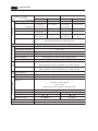
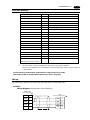
General Specifications
Type
UG221
UG220
Item
Rated Voltage
24V DC
24V ± 10% DC
Power Supply
Permissible Range
of Voltage
10ms or less
Permissible Momentary Power Failure
Demand
Physical Environment
10W or less
20W or less
15A
1ms
15A
1.5ms
Rushed Electric Current
With-stand voltage
DC external terminals to FG : 500V AC per min.
Insulation Resistance
500V DC, 10MΩ or more
Ambient Temperature
0°C to +50°C
-10°C to +60°C
Storage Ambient Temperature
Ambient Humidity
85% RH or less (without dew condensation)
Dust
No conductive dust
Solvent Resistance
No cutting oil or no organic solvent to cling to the unit
Corrosive Gas
No corrosive gas
Vibration Resistance
Mechanical
Working
Conditions
UG320
Vibration frequency: 10 to 150Hz, Acceleration: 9.8m/s2,
Single amplitude:0.075mm ,3 directions of X, Y and Z: one hour
Shock Resistance
Pulse shape: Sine half wave,
Electrical
Working
Conditions
Peak acceleration: 147m/s2, 3 directions of X, Y and Z: six times
Noise Resistance
Noise voltage: 1500Vp-p, noise width: 1µs
Contact: 6kV , Air: 8kV
Static Electricity Discharge Resistance
Mounting Conditions
Grounding
Grounding resistance: less than 100Ω
Structure
Protection structure: front panel complies with IP65 (when using gasket)
rear panel complies with IP20
Form: in a body
Mounting procedure: inserted in a mounting panel
Cooling System
Cooling naturally
Weight
Dimensions W
Approx. 0.8kg
H
D (mm)
182.5 138.8 50
+0.5
-0
+0.5
-0
Approx. 0.8kg
182.5 138.8
+0.5
-0
57.3*1
+0.5
-0
Approx. 1.1kg
230 175 66.1
+0.5
Panel Cut-out (mm)
174
Case Color
DARK GREY
BLACK*2
DARK GREY
PC/ABS
PC/PS
PC/ABS
Material
131
*1 including 4mm, the size of boss for communication unit
*2 equivalent to the Munsell color system N-2.0
174
131
220.5 -0
+0.5
165.5-0
1 - 22
8 Specifications
UG420
Type
AC Power Supply
Item
Rated Voltage
Power Supply
Permissible Range
of Voltage
Permissible Momentary Power Failure
Demand
Rushed Electric Current
UG520
DC Power Supply
AC PowerSupply
DC Power Supply
100/240V AC
24V DC
100/240V AC
24V DC
85 to 265V AC
24V ± 10% DC
85 to 265V AC
24V ± 10% DC
(47 to 440Hz)
(47 to 440Hz)
20ms or less
10ms or less
20ms or less
10ms or less
45VA or less
25W or less
50VA or less
25W or less
20A : 100V AC
30A
20A : 100V AC
30A
30A : 200V AC
6ms
30A : 200V AC
6ms
With-stand voltage
AC external terminals to FG: 1500V AC per min.
Physical Environment
DC external terminals to FG: 500V AC per min.
Insulation Resistance
500V DC, 10MΩ or more
Ambient Temperature
0°C to +50°C (UG420 STN Color : 0°C to +40°C )
85% RH or less (without dew condensation)
Ambient Humidity
No conductive dust
Dust
No cutting oil or no organic solvent to cling to the unit
Solvent Resistance
No corrosive gas
Corrosive Gas
Vibration frequency: 10 to 150Hz, Acceleration: 9.8m/s2,
Vibration Resistance
Mechanical
Working
Conditions
-10°C to +60°C
Storage Ambient Temperature
Single amplitude: 0.075mm, 3 directions of X, Y and Z: one hour
Pulse shape: Sine half wave,
Shock Resistance
Mounting Conditions
Electrical
Working
Conditions
Peak acceleration: 147m/s2, 3 directions of X, Y and Z: six times
Noise voltage: 1500Vp-p, noise width: 1µs
Noise Resistance
Contact: 6kV , Air: 8kV
Static Electricity Discharge Resistance
Grounding
Grounding resistance: less than 100Ω
Structure
Protection structure: front panel complies with IP65 (when gasket using)
rear panel complies with IP20
Form: in a body
Mounting procedure: inserted in a mounting panel
Cooling naturally
Cooling System
Approx. 2.5kg
Weight
Dimensions W
H
Panel Cut-out (mm)
Case Color
Material
D (mm)
310
240
+0.5
289-0
Approx. 3.0kg
92.3
334
270
+0.5
-0
216.2+0.5
313 -0
DARK GREY
PC/ABS
95.8
+0.5
246.2 -0
8 Specifications
1 - 23
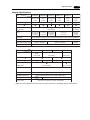
Display Specifications
Type UG220H-L
Item
Display Device
Resolution W
Dot Pitch W
UG220H-S UG221H-L
UG221H-T
UG320H
STN
STN
STN
TFT
STN
Monochrome
Color
Monochrome
Color
Color
LCD
LCD
LCD
Color
LCD
LCD
H (dots)
H (mm)
UG221H-S
STN
0.36
0.36
0.12
0.36
320
240
0.36
0.36
0.12
Effective Display Area
115.2
W
(5.7 inches)
H (mm)
LCD
640
0.36
0.36
480
0.36 0.082 0.246
157.4
86.4
118.1
(7.7 inches)
128 colors
+ blinking
16 colors
Color
Monochrome
8 gradation
+ blinking
Back-light
Cold cathode rectifier (which can be exchanged by a user except for UG221)
16 colors
+ blinking
The lamp is lit when the power is supplied.
Type
Item
Display Device
Dot Pitch W
UG420H-S
UG420H-V
STN
TFT
Color LCD
Color LCD
Color LCD
640
0.11
0.33
480
0.33
800
0.33
211.2
W
(10.4 inches)
H (mm)
Color
Back-light
Contrast Adjustment
Back-light Average Life*
UG520H-V
TFT
H (dots)
H (mm)
UG420H-T
Effective Display Area
Power Lamp
Approx.
40,000h
Approx. 50,000h
Approx. 40,000h
Power Lamp
Resolution W
+ bl i n k i n g
By function switches (only in case of STN type)
Contrast Adjustment
Back-light Average Life*
16 colors
Monochrome
8 gradation
+ blinking
0.264
0.264
158.4
600
0.3075 0.3075
246.0
184.5
(12.1 inches)
128 colors + blinking 16 colors
Cold cathode rectifier (which can be exchanged by a user)
By function switches (only in case of STN type)
Approx.
25,000h
Approx. 50,000h
The lamp is lit when the power is supplied.
* When the normal temperature is 25, and the surface luminance of the display is 50% of the default.
1 - 24
8 Specifications
Display Function Specifications (All the UGx20 series)
Item
Specifications
Display Language
Japanese
Eng./W. Europe
Chinese
Characters
ANK code
ASCII code
ASCII code
ASCII code
Chinese
1/4-size, 1-byte
2-byte (16-dot) JIS 1st and 2nd
2-byte (32-dot)
Size of Characters
JIS 1st
Chinese (simplified)
Korean
ASCII code
ASCII code
Chinese (simplified) Hangul (without Kanji)
ASCII code
1/4-size : 8
8 dots
1-byte : 8
16 dots
2-byte : 16
16 dots or 32
32 dots
Enlarge : W, 1 to 8 H, 1 to 8
Number of Characters
Resolution
320
240
640
480
800
600
1/4-size
40 columns
30 lines 80 columns 60 lines 100 columns 75 lines
1-byte
40 columns
15 lines 80 columns 30 lines 100 columns 37 lines
2-byte
20 columns
15 lines 40 columns 30 lines 50 columns 37 lines
Property of Characters
Display property : normal, reverse, blinking, bold, shadow
Color : 128 colors + blinking 16 colors / 16 colors + blinking
/ Monochrome 8 gradation + blinking
Kind of Drawing
Lines : line, continuous lines, box, parallelogram, polygon
Circles : circle, arc, sector, ellipse, elliptical arc, elliptical sector
Others : tile patterns
Property of Drawing
Type of lines : 6 types (fine, thick, dot, chain, broken, two-dot chain)
Tile patterns : 16 types (incl. user-definable 8 types)
Display property : normal, reverse, blinking
Display color : 128 colors + blinking 16 colors / 16 colors + blinking
/ Monochrome 8 gradation + blinking
Color specification : foreground, background, boundaries (line)
8 Specifications
1 - 25
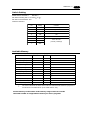
Function Performance Specifications (All the UGx20 series)
Specifications
Item
Screens
Max. 1024
Screen Memory
FP-ROM (flash memory), Appox. 2,816Kbytes* (different from the language)
Switches
768 per screen (192 per screen for UG221/220 : However, the number of
memory settings is limited.) *3
Actions of Switch
Set, reset, momentary, alternate, to light
possible to press a function switch and a display switch at the same time
(With UG221, 2 switches on the display can be pressed at the same time.)
Lamps
Reverse, blinking, exchange of graphics
768 per screen (192 per screen for UG221/220 : However, the number of
memory settings is limited.) *3
Graphs
Pie, bar, panel meter and closed area graph can be displayed without limit.
Total capacity per screen: within 128KB
Statics and trend graphs: Max. 256 per layer
*2
(However, the number of memory settings is limited.)
*3
1
Data Setting
Numerical Data Display No limits, total capacity per screen: within 128 KB
(However, the number of memory settings is limited.)
*3
Character Display
No limits, total capacity per screen: within 128 KB
(However, the number of memory settings is limited.)
*3
Message Display
Resolution : 320 240, Max. 40 characters
640 480, Max. 80 characters
800 600, Max. 100 characters
No limits, total capacity per screen: within 128 KB
(However, the number of memory settings is limited.)
*3
Messages
6144 lines
Sampling
Sampling display of buffer data
(constant sample, bit synchronize, bit sample, relay sample, alarm function)
Multi-Overlaps
Max. 1024
Data Blocks
Max. 1024
Graphic Libraries
Max. 2560
Patterns
Max. 1024
Macro Blocks
Max. 1024
Page Blocks
Max. 1024
Direct Blocks
Max. 1024
Screen Blocks
Temp. CTRL / PLC 2 Way
Max. 1024
Max. 32 *4
Calendar
provided
Hard-Copy
provided
Buzzer
provided, 2 types (intermittent short and long sounds)
Back-light Auto OFF Function ON at all time, specified freely
Self-test function of switches
Self-diagnostic Function
Check function of communication parameter setting
Check function of communication
*1 Screen memory capacity of the main unit with the following or newer hardware version
(Approx. 760k bytes for older versions or UG221/UG220)
For hardware version, check the value of the 3rd digit from the left in "Ser. No." line on the rear of the main unit:
UG520H-V
6; UG520H-S
5; UG420H-V
8; UG420H-T
9; UG420H-S
7; UG320H
4
*2 Layer : 4 per screen (base + 3 overlaps)
*3 For the memory setting limit, refer to the User's Manual <Function> (FEH376).
*4 The main unit with the following or newer hardware version is adapted to the temperature controller network:
UG520H-V
4; UG520H-S
3; UG420H-V
5; UG420H-T
5; UG420H-S
4; UG320H
7
8 Specifications
1 - 26
Touch Panel Specifications (All the UGx20 series)
Item
Specifications
Switch Resolution
Analog, 1024(W)
1024(H)
Matrix type, UG221: 20(W)
12(H) pcs
Form
Resistance film form
Life of Touch Panel
Use of one million times or more
Function Switch Specifications (All the UGx20 series)
Item
Specifications
Number of Switches
8 (6 for UG221/UG220)
Type of Switch
Pressure sensitive switches
Life of Switch
Use of one million times or more
Interface Specifications (All the UGx20 series)
Item
Specifications
Serial Interface
RS-232C, RS-422/485
for connecting PLC
Asynchronous type
(D-sub 25 pins, female)
Data length: 7, 8 bits
Parity: even, odd, none
Stop bit: 1, 2 bits
Baud rate: 2400, 4800, 9600, 19200, 38400, 57600, 115000bps
(115200bps is invalid for UG221/UG220.)
Serial Interface 1 and 2 for
RS-232C, RS-422/485 (2-wire connection)
transferring data
UG00P-MR, Bar code, UG00P-U2, Multi-link 2,
/other external
Temperature control network, UG-Link
(modular jack, 8 pins)
Printer Interface
Complies with centronics, half pitch 36 pins (for PC98x1)
NEC
: PR201
EPSON : compatibles with ESC/P24-84 or later
HP
: PCL Level 3
CBM292/293 printer (The screen copy cannot be printed out.)
Drawing Environment (All the UGx20 series)
Item
Specifications
Drawing Method
Exclusive drawing software
Drawing Tool
Name of exclusive drawing software
Personal computer
OS
: UG00S-CW
: Pentium2 450 MHz or above recommended
: Microsoft Windows 98 / Me / NT version 4.0 / 2000 / XP
Capacity of hard disk required
Display
: resolution of 640
(800
: free area of approx. 460MB or more
(for minimum installation : approx. 105Mbyte)
480 or more
600 is recommended)
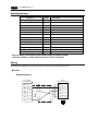
9 Serial Connector (CN1)
9
1 - 27
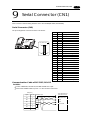
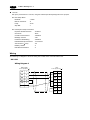
Serial Connector (CN1)
CN1 is used for communicating between a PLC and a POD(RS-232C, RS-422/485).
Serial Connector (CN1)
The pin arrangement of serial connector is as follows:
L
100240VAC
N
NC
)
CN1
CN1 (Dsub 25pin
MJ2
1
MJ1
CN2
Signal
1
FG
Frame ground
2
SD
RS-232C send data
3
RD
RS-232C receive data
4
RS
RS-232C RS request to send
5
CS
RS-232C CS clear to send
SG
Signal ground
Not used
6
14
7
8
13
Contents
Pin No.
25
Not used
9
+5V
Use prohibited
10
0V
Use prohibited
11
Not used
+SD
12
RS-422 send data (+)
13
-SD
RS-422 send data (-)
14
+RS
RS-422 RS send data (+)
15
Not used
16
Not used
-RS
RS-422 RS send data (-)
18
-CS
RS-422 CS receive data (-)
19
+CS
RS-422 CS receive data (+)
17
20
Not used
21
Not used
22
Not used
23
Not used
24
+RD
RS-422 receive data (+)
25
-RD
RS-422 receive data (-)
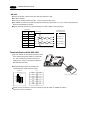
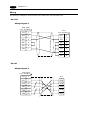
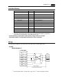
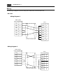
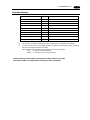
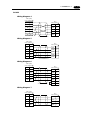
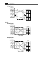
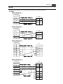
Communication Cable of RS-232C/RS-422
RS-232C
In case of RS-232C, SD and SG, and RD and SG form a pair.
Connect the shielded cable to pin No. 1 or the connector case cover.
POD (CN1)
Shielded cable
To the RS-232C port
of the PLC link unit
Signal
Pin No.
FG
1
Receive data
SD
2
SG
RD
3
SG
RS
4
Send data
CS
5
SG
7
1 - 28
9 Serial Connector (CN1)
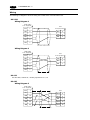
RS-422
In case of RS-422, +SD and -SD, and +RD and -RD form a pair.
Use SG if possible.
Connect the shielded cable to pin No. 1 or the connector case cover.
Use UG00P-TC which is the optional equipment made by Fuji Electric. Co., Ltd. in case of using terminal
blocks in RS-422/485 connection.
Specify terminal resistance by the dip switches on POD. (Refer to the next page.)
POD (CN1)
Signal
Pin No.
FG
1
To the RS-422 port
of the PLC link unit
Shielded cable
+RD
24
Send data (-)
-RD
25
Send data (+)
+SD
12
Receive data (-)
-SD
13
Receive data (+)
SG
7
SG
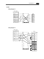
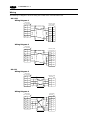
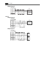
Terminal Blocks of RS-422/485
L
100240VAC
N
NC
CN1
Connect UG00P-TC (Terminal Converter) which
is the optional equipment made by Fuji Electric.
Co., Ltd. to POD via the serial connector on
POD (CN1) in case of using terminal blocks in
RS-422/485 connection.
MJ2
MJ1
CN2
UG00P-TC
CN
1
The RS-422 signal wiring of UG00P-TC is
connected to the serial connector (CN1).
SW
TB
1
1
CN1
SW1 (set to top:
4-wire connection)
Signal
Pin No.
FG
1
SG
7
UG00P-TC (Terminal Converter)
TB1
RD+
RDSD+
+SD
12
-SD
13
+RD
24
-RD
25
SDSG
FG
Specify 4-wire connection or 2-wire connection by the dip switch on UG00P-TC (SW1).
(set to top: 4-wire connection)
10 Setting of Dip Switches
10
1 - 29
Setting of Dip Switches
Setting of Dip Switches (DIPSW)
ON
1
Memory Extension 2
(invalid for UG220)
2
3
4
5
6
Not used
7
8
Terminal resistance of MJ2(modular jack 2)
But, it depends on a hardware version.
RD terminal resistance of pin No. 24 and 25
Terminal resistance of MJ1(modular jack 1)
Keep DIPSW 2, 3, 4 and 5 (not used) OFF.
Setting of Memory Extension 2 (This dip switch is invalid for UG220. Keep DIPSW 1 OFF.)
• Set DIPSW 1 ON in case of selecting “Memory Extension 2.”
(Refer to Chapter 3 “4.Connecting the Memory Extension unit.” )
Setting of Terminal Resistance depends on the hardware version of the unit.
UG520 , UG420 -> O, UG320 -> D, UG221 -> A,
For hardware version , check the value of the 3rd digit from the left in “Ser. No.” line on the rear of the
main unit.
1. In case that the hardware version is the lower-case letter.
Set DIPSW 7 ON in case of connecting with CN1 by connection of RS-422/485.
Set DIPSW 6 (DIPSW8) ON in case of connecting with Modular Jack 1/2 by the connection as below.
Multi-link2 communication (master)
Temperature controller communication by connection of RS-485
Card Recorder : UG00P-MR (option) is used
Serial Extension I/O : UG00P-U2 (option) is used
Terminal POD connected with UG-Link by connection of RS-485
•
•
2. In case that the hardware version is the capital letter.
Set DIPSW 7 ON in case of connecting with CN1 by the connection of RS-422/485.
Set DIPSW 6 ON in case of connecting with Modular Jack 1 by connection as below.
Multi-link2 communication (master)
Temperature controller communication by connection of RS-485
Card Recorder : UG00P-MR (option) is used
Serial Extension I/O : UG00P-U2 (option) is used
Terminal POD connected with UG-Link by connection of RS-485
The terminal resistance of MJ 2 is always ON.
•
•
•
1 - 30
11 Modular Jack 1 & 2
11
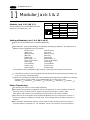
Modular Jack 1 & 2
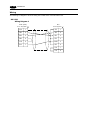
Modular Jack 1 & 2 (MJ1/2)
The right diagram is the pin arrangement and the
signal name of modular jack 1 & 2.
MJ1/2
12345678
Pin No.
1
2
3
4
5
6
7
8
Signal
+SD/RD
-SD/RD
+5V
+5V
0V
0V
RD
SD
Contents
RS-485 + data
RS-485 - data
Output power supply
Max. 150mA
Signal ground
RS-232C receive data
RS-232C send data
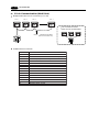
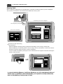
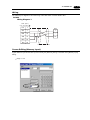
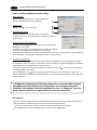
Setting of Modular Jack 1 & 2 (MJ1/MJ2)
Specify the use of MJ1/MJ2 by the software (UG00S-CW).
Select [Modular...] from [System Setting]. The [Modular Jack] dialog is displayed. The setting items of
[Modular Jack 1] and [Modular Jack 2] as follows.
Modular Jack 1
Modular Jack 2
[Editor port]
[Not used]
[Memory Card]
[Memory Card]
[Barcode]
[Barcode]
[UG00P-U2]
[UG00P-U2]
[Multi-Link]*1 *2
[Multi-Link]*1 *2
[Temp. CTRL Net]*2
[Temp. CTRL Net]*2
[UG-Link]*2
[UG-Link]*2
[Touch Switch]
[Touch Switch]
[Ladder Tool]
[Ladder Tool]
[Serial Printer]
[Serial Printer]
It is impossible to select both [Multi-Link] and [Temp. CTRL Net] in each setting of modular jack.
*1
It is possible to select this item when [Multi-Link 2] is selected for [Connection] and [Local Port] is set
to [1] in the [Comm. Parameter] dialog.
*2 [Multi Link 2 (master)] and [Temperature Control Network] and [UG-Link] are available in the following
hardware version or later of POD. As for UG220/UG221, any version can be used.
UG520H-V
4, UG520H-S
3, UG420H-V
5, UG420H-T
5, UG420H-S
4, UG320H
7
Editor Transferring
Use modular jack 1 (MJ1) in case of editor transferring.
When [Editor port] is selected for [Modular Jack 1] in the [P2] menu, it is also possible to transfer the
data while running, because the auto change of the local mode and the run mode is valid.
When [Editor port] is selected, on-line editing and the simulation mode are also available.
When the item other than [Editor port] is selected for [Modular Jack 1] in the [P2] menu, be sure to
transfer the data by the software in the local mode. On-line editing and the simulation mode are not
available.
When the data is transferred by software, use the cable for data transferring which is the optional
equipment made by Fuji Electric Co., Ltd. (UG00C-T: 3m) to connect POD to a personal computer.
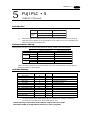
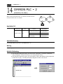
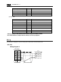
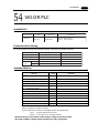
12 Bar Code Reader Interface
12
1 - 31
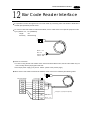
Bar Code Reader Interface
It is possible to receive the signal from a bar code reader by connecting a bar code reader to POD via the
modular jack (MJ1/MJ2) of POD series.
12345678
To connect a bar code reader to POD via MJ1/MJ2, use the cable which is the optional equipment made
by Fuji Electric. Co., Ltd. (UG00C-B).
Length
: 3m
Accessory : Modular Plug
Brown : +5V
Red : 0V
Orange : RXD
Yellow : TXD
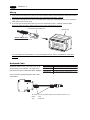
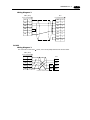
Notes on Connection
In case of using the bar code reader which uses the CTS and RTS control, the bar code reader may not
work normally without jumping RTS and CTS.
The output power supply (+5V) is max. 150mA. (Refer to the preview page.)
•
•
12345678
When the bar code reader connected to UG400 is used, connect it to UGx20 by the following cable.
Barcode Reader
Signal
RTS
TXD
RXD
CTS
SG
+5V
D-sub 9pin (
)
Pin No. Signal
1
CTS
2
RXD
3
TXD
4
RTS
5
6
7
SG
8
9
+5V
*
Orange : RXD
Yellow : TXD
* Jump pins, 1(CTS) and 4(RTS).
Red : 0V
Brown : +5V
1 - 32
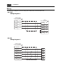
13 Printer Interface (CN2)
13
Printer Interface (CN2)
When a printer is connected to POD via the connector (CN2), it is possible to hard-copy the screen
display of POD, the data sheet, or the sampling data.
To connect a printer to POD, use the parallel interface cable of 36 pins which is optional equipment made
by Fuji Electric. Co., Ltd. (UG00C-C).
When using CBM292/293 printer, our printer cable be (UG00C-A) is available.
L
100240VAC
N
CN1
NC
MJ2
MJ1
CN2
to Printer
Half pitch 36 pins
Centronics
TB1
(+)
24V DC
(-)
to Printer
CN2
UG220
Compatible Printer Control Code System and Printer Models
NEC
PC-PR201 series
EPSON
Compatibles with ESC/P24-84 or later
HP(HEWLETT PACKARD) PCL Level 3
CBM292/293
Line thermal panel printer made by CBM Corporation.
(The screen copy cannot be printed out.)
Note of Usage of SRAM Memory Card (UG00K-Sx) or SRAM Cassette (UG00P-SR•UG221P-SR);
In case of connecting a printer to UGx20 series with a “UG00K-xx(Memory Card:SRAM)” or “UG00PSR•UG221P-SR (SRAM cassette)” at all times, be sure to turn off a printer at the same time when turning
off UGx20. If a printer is not turned off when UGx20 is turned off, the voltage will circulate from the power
supply line of a printer to make the power consumption of SRAM cassette’s backup battery increase, and
finally, the backup battery will consume drastically within a few months.
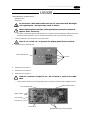
14 Video Interface
14
1 - 33
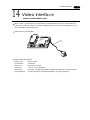
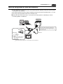
Video Interface
(Option: UG520/UG420 only)
When a video or a CCD camera is connected to the optional UGx20 which has a video interface, the
image which is taken by a video or a camera is displayed directly in a screen of UGx20 series (only in
case of UG520H-V and UG420H-T/V).
Video Interface of UGx20: BNC
L
100240VAC
N
NC
CN1
BNC
MJ2
MJ1
CN2
Video Display Specifications
Display Color
: 262,144 colors
Input Channel
: 4 Channels
Signal Form
: NTSC type, PAL type
Video Input
: 1.0Vp-p 75 ohm unbalance
Display Size
: 640 480, 640 240, 320 240, 160 120 dots (possible to change the size)
Color Adjustment : contrast (256 steps), brightness (256 steps), color gain (256 steps)
1 - 34
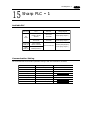
15 Analog RGB Input
15
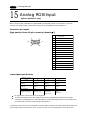
Analog RGB Input
(Option: UG420H-T only)
When connector CN3 of UG420H-TC (analog RGB input adapted product) is connected to a personal
computer, the screen image of the personal computer can be displayed on the UG420H-TC.
Connector pin layout
[high density D-sub 15-pin connector (female
)]
Input signal
5
1
10
6
15
11
1
Video signal (red wire)
2
Video signal (green wire)
3
Video signal (blue wire)
4
NC
5
Ground
6
Ground
7
Ground
8
Ground
9
NC
10
Ground
11
NC
12
NC
13
Horizontal synchronizing signal
14
Vertical synchronizing signal
15
NC
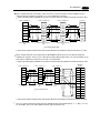
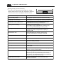
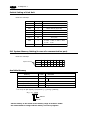
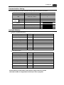
Input signal specification
Displayed number
of dots
Color
max. 262,144 colors max. 262,144 colors max. 262,144 colors
Horizontal synchronizing
frequency
31.5KHz
24.9KHz
31.5KHz
Vertical synchronizing
frequency
60Hz p-p
56Hz
70Hz
Input amplitude
0.7V
0.8V
0.7V
Windows screen
PC9801
DOS screen,
BIOS screens
DOS/V
BIOS screen
Sample main signals
640
480 dots
640
400 dots
p-p
720
350 dots
p-p
No signal other than the above can be displayed.
To display Windows screen, after displaying the [Control panel] dialog with the [Control panel]
command in the [Setting] menu under [Start Menu], double-click the [Screen] icon in this dialog, and
set refresh rate to 60 Hz in the [Screen property] window.
If a cable too long is used to connect between connector CN3 of UG420H-TC and the personal computer, the
screen image may be blurred due to noise. To prevent noise, it is recommended to mount a ferrite core.
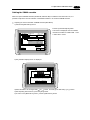
15 Analog RGB Input
1 - 35
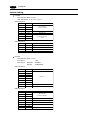
Touch-switch emulation function
With this function, you can manipulate the Windows screen displayed on the POD with touch
switches, i.e. without using the mouse.
Applicable version of screen development editor
This function is adapted to 2.4.0.0 or newer versions of the screen development editor.
Applicable version of POD system program
This function is adapted to 1.200 or newer versions of POD system program (SYSTEM PROG.VER.)
Touch panel driver to be installed
PN-WIN98/95 Ver. 2.00J (Japanese version) from GUNZE.
Operating environment of the access vision driver
Computer: DOS/V personal computer
OS:
Windows98/95
Restrictions
1. DOS application software that runs on MS-DOS prompt cannot be operated with touch panel.
2. This function is compatible with PS/2 mouse but may not with the unique pointing device of
manufacturer’s own development that is installed mainly in note type personal computer.
About setting
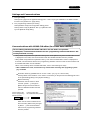
1. Select [Touch Switch] from [Modular Jack 1] or [Modular Jack 2] in the [Modular] dialog box of
[System Setting]. (When you want to display the symbols for DOS/V personal computer on the POD,
send the coordinate output of the touch panel to the DOS/V personal computer via the MJ port that is
set in this step.)
2. The touch panel driver supplied from GUNZE needs to be installed in the DOS/V personal computer
in advance. For how to install the driver, refer to the manual supplied with the GUNZE touch panel
driver.
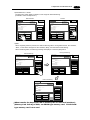
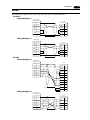
Example of setting
The procedure for adding the “touch-switch emulation” function under the environment where the analog
RGB input function is used is described below.
In this example, it is supposed that the following setting is already made:
On the [RGB Adjust] screen, [Setting 1] is set to “BIOS screen” while [Setting 2], to “Windows
screen”. (For details regarding the adjustment, see “Screen Adjustment” explained above.)
Connect between COM2 of the personal computer and MJ1 of the POD by means of UG00C-T (for
screen data transfer).
1. Change over to POD input screen (Windows screen is displayed).
2. Activate the screen development editor and open the file that is currently transferred to the POD.
3. Select [Touch Switch] from [Modular Jack 2] in the [Modular] dialog box of [System Setting].
1 - 36
15 Analog RGB Input
4. Save the file, and send it to the POD.
5. Mode is changed to RUN. In this mode, change screen over to the [RGB Input] screen.
(Windows screen is displayed.)
DOS/V Personal
POD
computer
6. In order to execute “touch-panel emulation”,
UG00C-T
Editor Port
MJ1
COM1
connect between COM1 (communication port) of
MJ2
the personal computer and MJ2 (touch switch)
COM2
Touch Switch
of the POD by means of UG00C-T.
7. Insert the “Touch Panel Driver PN-WIN98/95” floppy disk supplied from GUNZE in the floppy disk drive
and, from the files stored in the floppy disk, double-click “/Serial/setup.exe”. Then follow the directions
displayed on the screen to install the touch panel driver.
Then [Welcome!]
[Select destination to install]
[Install]
[Hardware setting] (See item 2 of the
notes described later.)
[Installation end]
[Install] Clicking the [OK] button here automatically
restart the personal computer. At the same time, the POD comes in RUN mode. Then change screen
over to the [RGB Input] screen to start Windows.
8. When Windows is started, the calibration software is automatically activated. Set items for calibration
(see item 3 of the notes described later).
This completes the installation of the touch panel driver.
9. When it is necessary to reset the “Touch Panel Driver PN-WIN98/95”, select menus as follows:
[Programs]
[Gunze]
[PN-WIN98_95 Serial]
[Touch panel driver]. Changes in the
[Start]
setting will take effect when the personal computer is started the next time.
* Notes
1. It is impossible to change over to the [Main Menu] screen from the Windows screen displayed on the
POD.
2. The [Hardware setting] dialog box is prepared for installing the touch panel driver. For [COM Port] in
this dialog box, select the COM port of the personal computer that is to be connected to the MJ port (for
touch switch) of the POD. For [Address] and [IRQ], set the address and IRQ of the selected COM port.
When you do not know which COM port of the personal computer to connect to the MJ port (for touch
switch) of the POD, or when you do not know the address or IRQ of the COM port, refer to the
instruction manual for the personal computer.
[Baud rate: 9600], [Parity: none], [Data bits: 8] and [Stop bits: 1] are fixed.
3. With the calibration software, correct the touch position and the mouse cursor indication position.
Touch as accurately as possible the red crosses that are displayed on the screen in the order of first
point (lower left on the screen), second point (upper right on the screen), third point (lower right on the
screen), and fourth point (upper left on the screen). Touch operation won’t be available if the calibration setting is not correctly completed. In such case, re-execute the setting.
4. Not that once the touch panel driver is installed, the serial port assigned for it won’t be able to be used
for other application till unless is uninstalled.
5. When your personal computer has only one COM (communication) port it is recommended to use other
personal computer for transferring POD screen.
16 Connection
16
1 - 37
Connection
1 : 1 Link Communication
One POD and one PLC are connected.
PLC
POD
run
stop
RS-232C or RS-422(RS-485)
1 : n Link Communication (Multi-drop)
One POD and multiple PLCs are connected. (n = 1 to 32)
POD
RS-485
run
stop
•••
•••
•••
•••
•••
•••
•••
•••
•••
•••
•••
•••
•••
•••
•••
•••
PLC1
run
stop
•••
•••
•••
•••
•••
•••
•••
•••
•••
•••
•••
•••
•••
•••
•••
•••
PLC2
run
stop
•••
•••
•••
•••
•••
•••
•••
•••
Maximum length 500m
(from POD to the last PLC)
•••
•••
•••
•••
•••
•••
•••
•••
PLC3
run
stop
•••
•••
•••
•••
•••
•••
•••
•••
•••
•••
•••
•••
•••
•••
•••
•••
PLCn
Available PLC for multi-link communication
Manufacturer
FUJI
MITSUBISHI
Models
MICREX-F series, FLEX-PC series, FLEX-PC COM
AnA/N/U series, QnA series, QnH(Q)series, A Link+Net10,FX series (A prt)
OMRON
SHARP
HITACHI
SYSMAC C, CV, CQM1, CS1 DNA
JW series, JW100/70H COM Port, JW20/30 COM Port
HIDIC-H
MATSUSHITA
YOKOGAWA
MEWNET
FA500, FA-M3, FA-M3R
YASKAWA
TOYOPUC
Koyo
Allen-Bradley
GE Fanuc
TOSHIBA
SIEMENS
SHINKO
SAMSUNG
KEYENCE
LG
FATEK
IDEC
MODICON
TAIAN
Memobus, CP9200SH/MP900
TOYOPUC
SU/SG, SR-T
PLC-5, SLC500, Micro Logix 1000
90 series
T series
S7-200 PPI
SELMART
SPC series, N_plus, SECNET
KZ series, KV series
MASTER-K500 / K1000, MASTER-K xxxS CNET
FACON FB series
MICRO3
Modbus RTU
TP02
Universal Serial
• • •
• • •
• • •
• • •
• • •
• • •
• • •
• • •
• • •
• • •
• • •
• • •
• • •
• • •
• • •
• • •
1 - 38
15 Connection
Multi-drop Communication (RS-485)
Refer to the PLC manual of each manufacturer for connection.
<E.g.>
The following example describes how one POD is connected to three PLCs made by MITSUBISHI.
See MITSUBISHI’s manual for further details.
POD (CN1)
Link unit
Link unit
Link unit
Signal Pin No.
Signal
Signal
Signal
FG
1
FG
FG
FG
+SD
12
RDA
RDA
RDA
-SD
13
RDB
RDB
RDB
+RD
24
SDA
SDA
SDA
-RD
25
SDB
SDB
SDB
SG
7
SG
SG
SG
SD/RD terminal resistance
(ON)
* Use twist shielded cable.
n : 1 Link Communication (Multi-link 2)
Up to 4 units can be connected to one PLC.
* Between a PLC and the POD master station is the same as those for 1:1 connection.
PLC
Communication between the stations : RS-485 (2-wire system), maximum length = 500 m
(a)
CN1
(b)
MJ2
POD Master
(local Port No. 1)
Terminal
block
(c)
(d)
(e)
CN1
CN1
CN1
POD Slave
(local Port No. 2)
POD Slave
(local Port No. 3)
POD Slave
(local Port No. 4)
Available PLCs for multi-link2.
As of October 2002, the PLCs supported are as follows. All the PLCs which are usable for 1:1 communication will be supported.
For the I/F driver, the Multi-Link 2 is supported by the version of 1.100 or later (screen development
software: version of 2.1.4.0 or later) and as for a POD master station, make sure the hardware version of
the unit is as follows.
As for UG221/UG220, any version can be used.
UG520H-V
4, UG520H-S
3, UG420H-V
5, UG420H-T
5, UG420H-S
4, UG320H
7
* The Multi-Link 2 cannot be used with a communication interface unit such as UG03I-T, J, E, C, S, P,
UG02I-T, J, S.
* The Multi-Link 2 cannot be used with Temperature controll network.
16 Connection
<Type>
<Calendar>
FUJI : MICREX-F series
Depends on the model
FUJI : MICREX-SX series
Provided
FUJI : MICREX-SX CPU
Provided
FUJI : FLEX-PC series
Depends on the model
FUJI : FLEX-PC CPU
Depends on the model
FUJI : FLEX-PC COM(T)
Provided
FUJI : FLEX-PC(T)
Depends on the model
FUJI : FLEX-PC CPU(T)
Depends on the model
MITSUBISHI : AnA/N/U series
Provided
MITSUBISHI : QnA series
Provided
MITSUBISHI : ACPU Port
Provided
MITSUBISHI : FX series
Depends on the model
MITSUBISHI : QnACPU Port
Provided
MITSUBISHI : QnHCPU Port (A)
Provided
MITSUBISHI : QnHCPU Port (Q)
Provided
MITSUBISHI : FX series Link(A prt)
Provided
MITSUBISHI : FX2N series
Depends on the model
MITSUBISHI : FX1S series
Provided
OMRON : SYSMAC C
Depends on the model
OMRON : SYSMAC CV
Provided
OMRON : SYSMAC CS1
Provided
SHARP : JW series
Provided
SHARP : JW100/70H COM Port
Provided
SHARP : JW20 COM Port
Provided
HITACHI : HIDIC-H
Provided
HITACHI : HIDIC-S10/2 alpha
Not provided
HITACHI : HIDIC-S10/ABS
Not provided
MATSUSHITA : MEWNET
Depends on the model
YOKOGAWA : FA500
Provided
YOKOGAWA : FA-M3
Provided
YOKOGAWA : FA-M3R
Provided
YASKAWA : Memobus
Depends on the model
YASKAWA : CP9200SH/MP900
Not provided
TOYOPUC
Provided
KOYO : SU/SG
Depends on the model
KOYO : SR-T
Provided
KOYO : SR-T(K prt)
Not provided
KOYO : SU/SG(K-Sequence)
Depends on the model
A.B : PLC-5
Not provided
A.B : SLC500
Provided
1 - 39
<Type>
<Calendar>
A.B : Micro Logix 1000
Not provided
GE Fanuc : 90 series
Not provided
GE Fanuc : 90 series(SNP-X)
Not provided
TOSHIBA : T series
Provided
SIEMENS : S5
Not provided
SIEMENS : S7
Not provided
SIEMENS : S5 UG400
Not provided
SIEMENS : TI500/505
Provided
SIEMENS : TI500/505(UG400)
Provided
SIEMENS : S5 PG port
Not provided
SIEMENS : S7-300MPI(HMI ADP)
Not provided
SIEMENS : S7-300MPI(PC ADP)
Not provided
SAMSUNG : SPC series
Not provided
SAMSUNG : N_plus
Provided
SAMSUNG : SECNET
Depends on the model
KEYENCE : KZ series
Not provided
KEYENCE : KZ-A500 CPU Port
Provided
KEYENCE : KZ/KV series CPU
Not provided
KEYENCE : KZ24/300 series CPU
Not provided
KEYENCE : KV10/24 series CPU
Not provided
KEYENCE : KV700 series CPU
Provided
LG : MASTER-K10/60/200
Not provided
LG : MASTER-K500/1000
Not provided
LG : LGMKX00S
Not provided
LG : MASTER-KxxxS CNET
Not provided
LG : GLOFACNET
Not provided
FANUC : Power Mate
Not provided
FATEK AUTOMATION: FACON FB series Provided
IDEC : MICRO3
Provided
MODICON : Modbus RTU
Depends on the model
YAMATAKE : MX series
Provided
TAIAN : TP02
Provided
SAIA : PCD
Provided
MOELLER : PS4
Not provided
Telemecanique : TSX Micro
Not provided
Automationdirect : Direct LOGIC
Depends on the model
Automationdirect
: Direct LOGIC(K-Sequence) Depends on the model
TOYO : uGPC sx series
Provided
TOYO : uGPC sx CPU
Provided
Up to 4 units can be connected to one PLC.
Use the terminal converter (UG00P-TC) , the optional equipment made by Fuji Electric Co., Ltd.
For details, please see the “User’s Manual <Multi-link 2 > (FEH364)”.
* Wire the shielded FG only at the one of both sides so that they are not connected.
Set the dip switch (SW1) of UG00P-TC as 2-wire connection when the UG00P-TC terminal converter is used.
•
(b)
POD Master
MJ1/2
+
-
SG
terminal resistance
(ON)
•
(c)
(d)
(e)
POD Slave
CN1+UG00P-TC
POD Slave
CN1+UG00P-TC
Terminal block
prepared by user
POD Slave
CN1+UG00P-TC
Signal
Signal
Signal
FG
FG
FG
+
+RD
+RD
+RD
-
-RD
-RD
-RD
+SD
+SD
+SD
-SD
-SD
-SD
SG
Signal
SG
SG
SG
terminal resistance
(OFF)
terminal resistance
(OFF)
terminal resistance
(ON)
Short-circuit between +RD and +SD , -RD and -SD when the UG00P-TC terminal converter is not used.
16 Connection
1 - 40
n : 1 Link Communication (Multi-link)
Multiple POD and a PLC are connected. (n=1 to 32)
POD 1
POD 3
POD 2
POD n
* The connections shown
below are not recommended.
RS-485
run
stop
•••
•••
•••
•••
•••
•••
•••
•••
•••
•••
•••
•••
•••
•••
•••
•••
Maximum length 500m
(from PLC to the last POD)
run
stop
PLC
Available PLCs for multi-link
Manufacturer
FUJI
MITSUBISHI
MITSUBISHI
OMRON
SHARP
HITACHI
MATSUSHITA
YOKOGAWA
YASKAWA
TOYOPUC
TOSHIBA
SIEMENS
SHINKO
SAMSUNG
LG
Models
MICREX-F series
AnA/N/U series, A link+Net10, FX series Link(A prt)
QnA CPU port (with UG00P-DI)
SYSMAC C series, CV series
JW series, JW100/70H COM Port, JW20/30 COM Port
HIDIC-H
MEWNET
FA500, FA-M3, FA-M3R
Memobus, CP9200SH/MP900
TOYOPUC
T series
S7-200 PPI
SELMART
SPC series, SECNET
MASTER-K500 / K1000
• • •
• • •
• • •
• • •
• • •
• • •
• • •
• • •
• • •
• • •
• • •
• • •
• • •
• • •
• • •
• • •
16 Connection
1 - 41
When multiple POD are connected to a link unit of PLC, use the terminal converter (UG00P-TC), the
optional equipment made by Fuji Electric. Co., Ltd. for RS-485 connection.
Set the dip switch (SW1) of UG00P-TC as 2-wire connection when the UG00P-TC terminal converter is used.
•
POD + UG00P-TC
POD + UG00P-TC
POD + UG00P-TC
Link unit
Signal
Signal
Signal
Signal
FG
FG
FG
FG
+SD
+SD
+SD
+RxD
-SD
-SD
-SD
-RxD
+RD
+RD
+RD
+TxD
-RD
-RD
-RD
-TxD
SG
SG
SG
SG
RD terminal resistance
(ON)
RD/SD terminal resistance
(ON)
RD/SD terminal resistance
(ON)
* Use twist shielded cable.
•
Short-circuit between +RD and +SD, and -RD and -SD when the UG00P-TC terminal converter is not used.
When multiple POD are connected directly to MITSUBISHI’s QnA CPU port, the optional equipment,
UG00P-DI is required. Also, the use of the optional cable, MB-CPUQT which is to connect UG00P-TC on
POD side to UG00P-DI on QnA CPU port side, is recommended.
Set the dip switch (SW1) of UG00P-TC as 2-wire connection when the UG00P-TC terminal converter is used.
•
POD + UG00P-TC
POD + UG00P-TC
POD + UG00P-TC
UG00P-DI
UG port
Signal
Signal
Signal
Pin No. Signal
FG
FG
FG
1
+SD
+SD
+SD
2
-SD
-SD
-SD
3
+TxD
+RD
+RD
+RD
4
+DSR
-RD
-RD
-RD
5
+DTR
SG
SG
SG
7
SG
15
-RxD
RD terminal resistance
(ON)
RD/SD terminal resistance
(ON)
* Use twist shielded cable.
RD/SD terminal resistance
(ON)
+RxD
16
-TxD
17
-DSR
18
-DTR
20
21
•
*
Short-circuit between +RD and +SD, and -RD and -SD when the UG00P-TC terminal converter is not used.
An n-to-1 system can be also configured using optional interface units (UG03I (02I)-S, -T, -J, -E(2), -C, or -P).
For the details, refer to the User’s Manual of each optional interface unit.
1 - 42
17 Operation of POD Main Menu
17
Operation of POD Main Menu
When the power of POD is turned on for the first time, the screen on the below left is displayed. After
transferring the screen data to POD, the following “Main Menu” is displayed.
When power is turned on for the first time:
"Main Menu" after trasferring data
UG420H-TC1M1
Main Menu
System Information
SYSTEM PROG. VER.1.000
Screen Data
Information
Size :
786432
1998- 9- 1
FONT
VER.1.000/1.000/1.000
JAPANESE 32
07 : 23 : 30
I/F DRV VER. 1.000
MELSEC AnA/N/U
Error: Stop
Time-Out: 0.50 sec
Retry: 3
PLC Type: MITSUBISHIAnA/N/U series
Comment:
Connection: 1 : 1
Signal Level: RS232C
PLC Stat.No.: 0
Editor : MJ1
Baud Rate: 19200
Data Length: 7
Stop Bit: 1
Parity: Even
Send Delay: 0msec
Memory-Card
I/O Test
If the screen data has been already transferred to POD, press the [SYSTEM] switch, then press the [F1]
switch. The [Main Menu] is displayed.
the [SYSTEM] switch
The "Main Menu" is displayed.
the [F1] switch
S
Y
S
T
E
M
S
Y
S
T
E
M
M
O
D
E
M
O
D
E
UG420H-TC1M1
Main Menu
System Information
SYSTEM PROG. VER.1.000
Screen Data
Information
Size :
786432
FONT
VER.1.000/1.000/1.000
JAPANESE 32
PLC Type: MITSUBISHIAnA/N/U series
Comment:
Connection: 1 : 1
Signal Level: RS232C
PLC Stat.No.: 0
Editor : MJ1
1998- 9- 1
07 : 23 : 30
I/F DRV VER. 1.000
MELSEC AnA/N/U
Error: Stop
Time-Out: 0.50 sec
Retry: 3
Baud Rate: 19200
Data Length: 7
Stop Bit: 1
Parity: Even
Send Delay: 0msec
Memory-Card
I/O Test
*The switches that are displayed on the [Main Menu] screen changes
with the option provided from the manufacturer, the communication
I/F unit installed, or the screen setting (temperature controller, etc.)
Main Menu
The “Main Menu” is the system menu for transferring the data between a personal computer and POD.
When the screen data is transferred from a personal computer to POD, the “Main Menu” must be displayed.
(If [Editor port] is selected for [Modular Jack 1] in the [P2] menu of the editing software or the on-line editing is
executed, it is not necessary to display the “Main Menu”.
17 Operation of POD Main Menu
System program version
1 - 43
Model name of POD
Font data version
Data size
UG420H-TC1M1
Main Menu
System Information
SYSTEM PROG. VER.1.000
Screen Data
Information
Size :
PLC type and comment
specified by the panel editor
786432
1998- 9- 1
FONT
VER.1.000/1.000/1.000
JAPANESE 32
Connection: 1 : 1
Signal Level: RS232C
PLC Stat.No.: 0
Own Stat.No.: 1
V6 Total: 2
Retry: 10
PLC I/F driver
version and name
Error: Stop
Time-Out: 0.50 sec
Retry: 3
PLC Type: MITSUBISHIAnA/N/U series
Comment:
Multi-Link
Multi-Link Network
Network
7 : 23 : 30
I/F DRV VER. 1.000
MELSEC AnA/N/U
Baud Rate: 19200
Data Length: 7
Stop Bit: 1
Parity: Even
Send Delay: 0msec
Setting of
comm. parameter
Multi-link setting
* This menu is displayed
Editor : MJ1
only in case of selecting [1:1]
in [Connection] of [Comm. Parameter].
Memory-Card
I/O Test
Setting of modular jack
b
a
"Main Menu" of UG221/UG220
Model name of
UG221/UG220
System program version
a
Main Menu
UG220H-SC4
1998- 7 -23
12:24:30
b
SYS PROG. VER. 0.591
I/O Test
Font data version
Memory
FONT VER.1.000/1.010/1.000
JAPANESE 32
I/F DRV VER.1.000
MELSEC AnA/N/U
-Card
c
Communication
Parameter
PLC I/F driver
version and name
PLC Type :
MITSUBISHI AnA/N/U series
Comment:
PLC type and
comment specified
by the panel editor
Editor:MJ1
Setting of modular jack
*
In case of UG221 and UG220, when the “Communication Parameter” switch on the “Main Menu” is
pressed, the following “Comm. Param.” is displayed.
12:24:30
Main Menu
Comm. Param.
I/O Test
Screen Data Size :
Memory
-Card
Multi-Link Network
Communication
Own Stat.No. : 1
V6 Total : 2
Retry : 10
Parameter
Connection :
Signal Level :
PLC Stat. No.:
Baud Rate :
Data Length :
Stop Bit :
Parity :
Send Delay :
Press the "Communication
Parameter" switch.
Multi-link setting
* This menu is displayed
only in case of selecting
[1 : 1] in [Connection] of
[Comm. Parameter].
Editor:MJ1
786432
Error : Stop
Time-out : 0.50 sec
Retry : 3
Multi-Link N
RS232C
00
19200
7
1
Even
20 msec
17 Operation of POD Main Menu
1 - 44
I/O Test
When the switch “a” on the “Main Menu” is pressed, the following “I/O Test” is displayed.
This is the test menu to check only POD hardware.
Memory-Card
I/O Test
B
E
C
Press the [I/O Test] switch.
D
I/O Test
Main Menu
SYS
F-1
Printer Check
Switch Check
F-2
A
F-3
Self-Loop Test
Please refer to the manual, "Hardware Specifications".
F-4
Communication Port
CTS
RTS
NG
OK
Self-Loop Test
*
F-5
CN1
RS-232C
MJ1
RS-485
F-6
MJ2
F-7
In case of UG221 and UG220, when the switch “A” on the “Main Menu” is pressed, the following “I/O
Test” is displayed.
Then, the “Serial Test” switch on the “I/O Test” is pressed. The following “Serial Test” is displayed.
The self-loop test can be executed on this screen.
12:24:30
I/O Test
Memory
-Card
Press the "I/O Test" switch.
Communication
Parameter
E
I/O Test
Main Menu
D
A
Press the "Serial Test" switch.
Serial Test
SYS
I/O Test
Self-Loop Test
Please refer to the manual,
"Hardware Specifications".
F-1
Communication Port
Printer Check
F-2
CTS
RTS
F-3
NG
OK
F-4
Serial Test
Self-Loop
Test
Switch Check
F-5
C
B
CN1
RS232C
MJ1
RS485
MJ2
17 Operation of POD Main Menu
1 - 45
A. Self-loop Test
This is the test menu to check the signals necessary for UG20 to communicate with PLC or a personal
computer by using only POD.
Signal Test of RS-232C in CN1
Select [CN1] and [RS-232C] in [Communication Port] by pressing each switch.
Communication Port
CN1
RS-232C
MJ1
RS-485
MJ2
•Loop-back Test
Check the signals, [SD] and [RD].
1 Jump pins, 2 and 3 of CN1.
2 The test is OK, if the [OK] lamp turns on when the [Self-Loop Test] switch is pressed.
* If the [NG] lamp turns on when the same switch as above is pressed, ask the
advice of your distributor.
CTS
RTS
CTS
RTS
NG
OK
NG
OK
Self-Loop Test
Self-Loop Test
•Test of CTS/RTS
Check the signals, [CTS] and [RTS].
1 Jump pins, 4(RTS) and 5(CTS) of CN1.
2
The test is OK if the [CTS] lamp and the [RTS] lamp turn on at the same time that the [RTS] switch is
pressed. Similarly, the test is OK if the [CTS] turns off at the same time that the [RTS] is turned off.
CTS
RTS
CTS
RTS
NG
OK
NG
OK
Self-Loop Test
Self-Loop Test
CTS
RTS
CTS
RTS
NG
OK
NG
OK
Self-Loop Test
Self-Loop Test
1 - 46
17 Operation of POD Main Menu
Signal Test of RS-485 in CN1
Select [CN1] and [RS-485] in [Communication Port] by pressing each switch.
Communication Port
CN1
RS-232C
MJ1
RS-485
MJ2
•Loop-back Test
Check the signals, [SD] and [RD].
1
2
Jump each pin, 12 and 24, 13 and 25 of CN1.
The test is OK, if the [OK] lamp turns on when the [Self-Loop Test] switch is pressed.
CTS
RTS
CTS
RTS
NG
OK
NG
OK
Self-Loop Test
Self-Loop Test
*If the [NG] lamp turns on when the same switch as above is pressed, ask the
advice of your distributor.
•Test of CTS/RTS
Check the signals, [CTS] and [RTS].
1
2
Jump each pin, 14(+RTS) and 19(+CTS), 17(-RTS) and 18(-CTS) of CN1.
The test is OK if the [CTS] lamp and the [RTS] lamp turn on at the same time that the [RTS] switch
is pressed. Similarly, the test is OK if the [CTS] turns off at the same time that the [RTS] is turned off.
CTS
RTS
CTS
RTS
NG
OK
NG
OK
Self-Loop Test
Self-Loop Test
CTS
RTS
CTS
RTS
NG
OK
NG
OK
Self-Loop Test
Self-Loop Test
17 Operation of POD Main Menu
1 - 47
Signal Test of RS-232C in MJ1 and MJ2
Select [MJ1] (or [MJ2]) and [RS-232C] in [Communication Port] by pressing each switch.
Communication Port
CN1
RS-232C
MJ1
RS-485
MJ2
•Loop-back Test
Check the signals, [SD] and [RD].
Execute the test by connecting the data transfer cable (UG00C-T) to CN1.
1. Set the adaptor, ADP25-9, which is attached to UG00C-T, to UG00C-T. And connect the modular
jack side of UG00C-T to MJ1 (or MJ2), ADP25-9 side of UG00C-T to CN1.
UG00C-T
CN1
MJ1/2
2. The test is OK, if the [OK] lamp turns on when the [Self-Loop Test] switch is pressed.
CTS
RTS
CTS
RTS
NG
OK
NG
OK
Self-Loop Test
Self-Loop Test
* If the [NG] lamp turns on when the same switch as above is pressed, ask the
advice of your distributor.
Signal Test of RS-485 in MJ1 and MJ2
When you execute the signal test of RS-485 in MJ1 and MJ2, ask the advice of your distributor.
17 Operation of POD Main Menu
1 - 48
B. Printer Check
Check the signal of printer.
The test is OK if the test printout is executed satisfactorily when connecting POD to a printer and pressing
this [Printer Check] switch.
!"#$%&@
!"#$%&@
!"#$%&@
!"#$%&@
!"#$%&@
!"#$%&@
!"#$%&@
0123456789
0123456789
0123456789
0123456789
0123456789
0123456789
0123456789
ABCDEFGHIJKLMNO
ABCDEFGHIJKLMNO
ABCDEFGHIJKLMNO
ABCDEFGHIJKLMNO
ABCDEFGHIJKLMNO
ABCDEFGHIJKLMNO
ABCDEFGHIJKLMNO
C. Switch Check
Check the reaction of the touch switches on the POD panel.
When the [Switch Check] switch is pressed, the following screen is displayed.
The switch check screen is displayed.
Main Menu
SYS
X:
Y:
F-1
Check
Switch Check
F-2
Retu
Eras
Press the [Switch Check] switch.
Confirm that the color of the pressed area changes into white.
The white color means that the switch reacts to the touch normally.
Pressing the [F4] switch leads to the previous [I/O Test] screen.
Pressing the [F5] switch deletes all the white dots.
X:
Y:
Retu
Eras
17 Operation of POD Main Menu
*
1 - 49
In case of matrix type
When pressing the [Switch Check] switch, the following screen which is divided by a minimum size of
switch is displayed. Confirm that the color of the pressed switch changes into white. Pressing the
corner right below leads to the previous [I/O Test] screen.
the [Switch Check] screen
Main Menu
SYS
F-1
Switch Check
F-2
If the pressed area is reversed, these
switches reacts to the touch normally.
Press
the [Switch Check] switch.
D. Test of SYSTEM & Function Switches
Check the eight switches (six switches for UG221 and UG220) placed vertically on the right side of the
POD panel.
The test is OK if the lamps on the screen turn on when each switch is pressed.
SYS
SYS
F-1
F-1
F-2
F-2
F-3
F-3
F-4
F-4
Press the [F4] switch.
F-5
The test is OK
when the [F-4] lamp is lit.
F-5
F-6
F-6
F-7
F-7
E. Main Menu
Pressing this [Main Menu] switch leads to the previous [Main Menu].
The "Main Menu" is displayed.
Main Menu
SYS
UG420H-TC1M1
Main Menu
System Information
F-1
Check
Switch Check
F-2
SYSTEM PROG. VER.1.000
Screen Data
Information
Size :
786432
PLC Type: MITSUBISHIAnA/N/U series
Comment:
Multi-Link
Multi-Link Network
Network
Press the [Main Menu] switch.
Own Stat.No.: 1
V6 Total: 2
Retry: 10
Editor : MJ1
FONT
VER.1.000/1.000/1.000
JAPANESE 32
Connection: 1 : 1
Signal Level: RS232C
PLC Stat.No.: 0
1998- 9- 1
7 : 23 : 30
I/F DRV VER. 1.000
MELSEC AnA/N/U
Error: Stop
Time-Out: 0.50 sec
Retry: 3
Baud Rate: 19200
Data Length: 7
Stop Bit: 1
Parity: Even
Send Delay: 0msec
Memory-Card
I/O Test
1 - 50
17 Operation of POD Main Menu
Memory-Card
When the [Memory-Card] switch on the “Main Menu” is pressed, the following “Memory-Card” is displayed.
This screen is to transfer the screen data between POD and a memory-card.
Memory-Card
I/O Test
The "Memory-Card" screen is displayed.
Press the [Memory-Card] switch.
Memory-Card
Main Menu
Port Selection
Modular Jack
MJ1
Memory-Card
Socket
Transfer
"Memory-Card" of UG220/UG221
Display <--- Card
Display ---> Card
Main Menu
Memory-Card
Port Selection
Transfer
Modular Jack
MJ1
Display <-- Card
Data Selection
Display --> Card
Screen Data
I/F Driver
Font Data
UG Program
Display <-> Card
Start
Display <--> Card
Data Selection
Screen Data
Font Data
Start
I/F Driver
UG Program
Cancel
Cancel
Procedure of Data Transferring
1)Port Selection
Select the [Modular Jack MJ1] switch (or [Modular Jack MJ2]) in case of using a modular jack.
Select the [Memory-Card Socket] switch in case of using a memory-card interface. When each switch is
pressed, the “Memory-Card Information” window is displayed.
In case of UG221 and UG220, pressing the “Close” switch leads to the original screen after checking the
memory card information.
Memory-Card
Memory-Card
Port Selection
Modular Jack
MJ1
Memory-Card
Socket
Main Menu
Memory-Card Information
Close
Port Selection
V6 Program
:
Modular Jack
Memory-Card
Version:-.--MJ1
Socket
Font Data
:
Version:-.---/-.---/-.--I/F Driver
:
Version:-.--Screen PLC Type:
Screen Comment:
Data Selection
Transfer
Display <--- Card
Display ---> Card
Display <--> Card
Screen Data
Font Data
Start
I/F Driver
UG Program
Cancel
In case of selecting [Memory Card] from [Modular Jack 2] in the [Others] dialog of
UG00S-CW, it is possible to select the [Modular Jack 2] switch in the [Port Selection]
menu of the [Memory-Card] screen on POD.
17 Operation of POD Main Menu
1 - 51
2)Data Selection, Transfer
Pressing each switch leads to selection of the target for data transferring.
(Possible to select multiple items.)
Data Selection
Transfer
Memory-Card
Memory-Card
Main Menu
Memory-Card Information
Close
Main Menu
Close
Memory-Card Information
Port Selection
Port Selection
Sys Program
:
Modular Jack
Memory-Card
Version:-.--MJ1
Socket
Font Data
:
Version:-.---/-.---/-.--I/F Driver
:
Version:-.--Screen PLC Type:
Screen Comment:
Sys Program
:
Modular Jack
Memory-Card
Version:-.--MJ1
Socket
Font Data
:
Version:-.---/-.---/-.--I/F Driver
:
Version:-.--Screen PLC Type:
Screen Comment:
Transfer
Display <--- Card
Display ---> Card
Display <--> Card
Data Selection
Transfer
Display <--- Card
Display ---> Card
Display <--> Card
Data Selection
Screen Data
Font Data
Start
Screen Data
Font Data
Start
I/F Driver
UG Program
Cancel
I/F Driver
UG Program
Cancel
3)Start
When the [Start] switch is pressed, the data transferring starts. During data transfer, the character,
“Start”, on the switch changes into the character,”Busy”, and the switch starts blinking.
After transferring data, the following message is displayed. Press the [OK] switch.
During transferring
Start transferring
Memory-Card
Memory-Card
Main Menu
Memory-Card Information
Close
Sys Program
:
Modular Jack
Memory-Card
Version:-.--MJ1
Socket
Font Data
:
Version:-.---/-.---/-.--I/F Driver
:
Version:-.--Screen PLC Type:
Screen Comment:
Data Selection
Main Menu
Memory-Card Information
Close
Port Selection
Port Selection
Sys Program
:
Modular Jack
Memory-Card
Version:-.--MJ1
Socket
Font Data
:
Version:-.---/-.---/-.--I/F Driver
:
Version:-.--Screen PLC Type:
Screen Comment:
Transfer
Display <--- Card
Display ---> Card
Display <--> Card
Data Selection
Transfer
Display <--- Card
Display ---> Card
Display <--> Card
Screen Data
Font Data
Start
Screen Data
Font Data
Busy
I/F Driver
UG Program
Cancel
I/F Driver
UG Program
Cancel
Finish transferring
Memory-Card
Main Menu
Memory-Card Information
Close
Port Selection
Sys Program
:
Modular Jack
Memory-Card
Version:-.--MJ1
Socket
Font Data
:
Version:-.---/-.---/-.--I/F Driver
:
Version:-.--Screen PLC Type:
Screen Comment:
Data Selection
Transfer
Display <--- Card
Display ---> Card
Display <--> Card
WorkScreen
nomally
finished.
Data
Font Data
Start
I/F Driver
OK
V6 Program
Cancel
* When transfer the data from POD to memorycard via the card interface(=
[Memory-Card Socket]) of POD, use SRAM type memory card. FLASH ROM
type memory card is not used.
1 - 52
17 Operation of POD Main Menu
Message Display in Data Transferring
If an error occurs during transferring data, the message
display window shown on the right is displayed. The kinds
and the contents of the messages are as shown below.
Message
Work nomally finished.
OK
Contents
Work normally finished.
The specified operation has been concluded normally.
UG00P-MR not connecting
UG00P-MR is not connecting when selecting a modular jack.
UG00P-MR Communication Error
A communication error occurred between POD and
UG00P-MR when selecting a modular jack.
Memory-Card not setting
A memory card is not inserted.
(Or in case of trying to write data into a memory card
when inserting FLASH ROM type memory card)
Memory-Card Capacity over
Cannot write the data into a memory card because
the data size in POD is larger than the capacity of
a memory card.
Write Protect : ON
Cannot write data into a memory card because
the write protect switch in a memory card is ON.
Writing Error occurred.
The error occurred while writing data into a memory
card.
Selected data does not exist.
The data in the reading target does not exist.
POD type is different.
The specified type of the data in POD is different from the
type of the memory card data.
Selected data can not be read.
The data in a memory card cannot be read.
Reading Error occurred.
The error occurred during writing data into a FLASH
ROM of POD.
Data discrepant
There is some discrepancy in data, when comparing data
between a memory card and POD.
Screen data on POD will be broken.
This message appears to inform the user that the data in
POD will be broken by transferring the font data (the size
which is larger than the present data) from a memory
card to POD. (The [OK] switch continues the transferring.
The [Cancel] switch stops transferring.)
Undefined Error occurred.
The error occurred due to some cause other than
the above mentioned.
17 Operation of POD Main Menu
1 - 53
Screen Adjustment [Option: UG420H-T(RGB input adapted product) only]
Depending on what type of personal computer is used, RGB output frequency for Windows screen, BIOS
screen or DOS screen changes. Therefore, adjustment is necessary.
When there is only one type of output frequency, select either “Setting 1” or “Setting 2”.
How to adjust
1. Display the local MAIN MENU screen.
Main Menu
UG420H-TC12
System Information
SYSTEM PROG. VER. 1.150
1998-5 -5
FONT
VER.1.000/01.020/1.000
JAPANESE 32
07:23:30
I/F DRV VER.1.100
MELSEC AnA/N/U
Screen Data PLC Type: MITSUBISHIAnA/N/U series
Error : Stop
Information
Time-Out : 0.50 sec
Comment : DEMO Screen
Size : 786432
Retry : 3
Connection : 1 : 1
Signal Level : RS-232C
PLC Stat.No. : 0
Baud Rate
Data Length
Stop Bit
Parity
Send Delay
: 19200
:7
:1
: Even
: 0msec
RGB Adjust
MemoryCard
Editor:MJ1
2.
I/O Test
With the [RGB Adjust] switch, display the [RGB Adjust] screen.
Main Menu
UG420H-TC12
System Information
SYSTEM PROG. VER. 1.150
1998-5 -5
FONT
VER.1.000/01.020/1.000
JAPANESE 32
07:23:30
I/F DRV VER.1.100
MELSEC AnA/N/U
Screen Data PLC Type: MITSUBISHIAnA/N/U series
Error: Stop
Information
Time-Out: 0.50 sec
Comment : DEMO Screen
Size : 786432
Retry: 3
Connection: 1 : 1
Signal Level: RS-232C
PLC Stat.No.: 0
Baud Rate:
Data Length:
Stop Bit:
Parity:
Send Delay:
19200
7
1
Even
0msec
RGB Adjust
MemoryCard
Editor:MJ1
I/O Test
[RGB adjustment] screen
RGB Adjust
Main Menu
Please refer to the manual, "Hardware".
Horizontal : 31180 Hz
Vertical : 59 Hz
Setting-1
Setting-2
Not used
Not used
Adjust
Adjust
Clear
Save
1 - 54
3.
17 Operation of POD Main Menu
First, BIOS screen is adjusted.
Press the [Adjust] switch in the [Setting 1] box to activate RGB display mode.
RGB Adjust
Main Menu
Please refer to the manual, "Hardware".
Horizontal : 31180 Hz
Vertical : 59 Hz
Setting-1
Setting-2
Not used
Not used
Adjust
Adjust
Clear
Save
With the BIOS screen displayed, adjust with switches [F • 1] to [F • 6].
[SYSTEM]
End of adjustment
[F • 1]
Vertical: Screen is moved downward.
[F • 2]
Vertical: Screen is moved upward.
[F • 3]
Horizontal: Screen is move rightward.
[F • 4]
Horizontal: Screen is moved leftward.
[F • 5]
Increments dots by +1.
[F • 6]
Decrements dots by -1.
* Adjustment of dots is made so that blurring is minimized.
BIOS Screen
ROM PCI/ISA BIOS ( 2A69KA1E )
COMS SETUP UTILITY
AWARD SOFTWARE, INC.
! ! CPU SOFT MENU II ! !
LOAD SETUP DEFAULTS
STANDARD CMOS SETUP
LOAD BIOS DEFAULTS
BIOS FETUREES SETUP
PASSWORD SETTING
CHIPSET FEATURES SETUP
IDE HARD DISK DETECTION
POWER MANAGEMENT SETUP
SAVE & EXIT SETUP
EXIT WITHOUT SAVING
PNP, PCI & ONBOAD I/O
Esc : Ouit
F10 : Save & Exit Setup
: Select Item
( Shift ) F2 : Change Color
CPU Name , Type , Speed . . .
When adjustment is completed, press the [SYSTEM] switch to return to the [RGB Adjust] screen.
ROM PCI/ISA BIOS ( 2A69KA1E )
COMS SETUP UTILITY
AWARD SOFTWARE, INC.
! ! CPU SOFT MENU II ! !
LOAD SETUP DEFAULTS
STANDARD CMOS SETUP
LOAD BIOS DEFAULTS
BIOS FETUREES SETUP
PASSWORD SETTING
CHIPSET FEATURES SETUP
IDE HARD DISK DETECTION
POWER MANAGEMENT SETUP
SAVE & EXIT SETUP
PNP, PCI & ONBOAD I/O
Esc : Ouit
F10 : Save & Exit Setup
EXIT WITHOUT SAVING
: Select Item
( Shift ) F2 : Change Color
CPU Name , Type , Speed . . .
17 Operation of POD Main Menu
4.
1 - 55
Then the Windows screen is adjusted.
Press the [Adjust] switch in the [Setting 2] box to activate RGB display mode.
RGB Adjust
Main Menu
Please refer to the manual, "Hardware".
Horizontal : 31180 Hz
Vertical : 59 Hz
Setting-1
Setting-2
Not used
Not used
Adjust
Adjust
Clear
Save
With the Windows screen displayed, adjust with switches [F • 1] to [F • 6].
When adjustment is completed, press the [SYSTEM] switch to return to the [RGB Adjust] screen.
1 - 56
5.
17 Operation of POD Main Menu
Press the [Save] switch to save the setting data. (The setting data is written in the flash ROM.)
RGB Adjust
Main Menu
Please refer to the manual, "Hardware".
Horizontal : 31180 Hz
Setting-2
Not used
Not used
Adjust
Adjust
Clear
6.
Vertical : 59 Hz
Setting-1
Save
By doing this, screen adjustment is completed.
Notes on RGB input
When there is no RGB input (when the cable is not connected), the mode cannot be changed over to
RGB display mode.
When bit 12 of read area (n+1) is set to “1”, the mode is changed over to RGB display mode the
moment RGB input is restored (the moment the cable is connected).
17 Operation of POD Main Menu
1 - 57
Setting for SRAM cassette
When the optional SRAM cassette (UG00P-SR, UG221P-SR) is installed in the POD main unit, it is
possible to adjust the internal calendar of the SRAM cassette or to format the SRAM cassette.
Adjusting the internal calendar of SRAM cassette (Main Menu)
1)Activate the [Main Menu] screen.
Main Menu
UG420H-TC12
System Information
SYSTEM PROG. VER. 1.150
1998-5 -5
FONT
VER.1.100/1.090/1.000
JAPANESE 32
Comment :
Connection : 1 : 1
Signal Level : RS-232C
PLC Stat.No. : 0
07:23:30
I/F DRV VER.1.100
MELSEC AnA/N/U
Screen Data PLC Type: MITSUBISHIAnA/N/U series
Information
Size : 2883584
Press the [Cassette Adjust] switch.
This switch is displayed when the SRAM
cassette is installed for FONT VER. 1.100/
1.090/1.000 or newer.
Error : Stop
Time-Out : 0.50 sec
Retry : 3
Baud Rate
Data Length
Stop Bit
Parity
Send Delay
: 19200
:7
:1
: Even
: 0msec
Cassette Adjust
MemoryCard
Editor:MJ1
I/O Test
2)The [Cassette Adjust] screen is displayed.
2000-6-26 14:38:51
Cassette Adjustment
Main Menu
Date and Time Adjustment
Date:
Time:
←
→
+
−
Set
Format of SRAM Cassette
* Formats SRAM cassette in the present screen data type.
Format
Execute
3)Select the data to be changed with [ ] or [ ] switch, and change the data with [+] or [-] switch.
4)After adjusting date and time, press the [SET] switch.
5)To return to the [Main Menu] screen, press the [Main Menu] switch.
1 - 58
18 Function Switches
Formatting the SRAM cassette
When you changed the setting of SRAM cassette area, be sure to format the SRAM cassette.
SRAM cassette can be formatted from the [Main Menu] screen.
If the format of the SRAM cassette does not coincide with the setting of screen data, the SRAM cassette
cannot be used (error No. 163 occurs.)
How to format the SRAM cassette
1)Activate the [Main Menu] screen.
•
Main Menu
UG420H-TC12
System Information
SYSTEM PROG. VER. 1.150
1998-5 -5
FONT
VER.1.100/1.090/1.000
JAPANESE 32
Comment :
Connection : 1 : 1
Signal Level : RS-232C
PLC Stat.No. : 0
07:23:30
I/F DRV VER.1.100
MELSEC AnA/N/U
Screen Data PLC Type: MITSUBISHIAnA/N/U series
Information
Size : 2883584
Press the [Cassette Adjust] switch. This
switch is available for FONT VER. 1.100/
1.090/1.000 or newer.
Error : Stop
Time-Out : 0.50 sec
Retry : 3
Baud Rate
Data Length
Stop Bit
Parity
Send Delay
: 19200
:7
:1
: Even
: 0msec
Cassette Adjust
Editor:MJ1
MemoryCard
I/O Test
2)With the [Cassette Adjust] switch, display the [Cassette Adjust] screen.
3)Press the [Format] switch and then the [Execute] switch.
Then the cassette is formatted the same as the currently displayed screen data, and you return to the
[Main Menu] screen.
2000-6-26 14:38:51
Cassette Adjustment
Main Menu
Date and Time Adjustment
Date:
Time:
←
→
+
−
Set
Format of SRAM Cassette
* Formats SRAM cassette in the present screen data type.
Format
Execute
17 Operation of POD Main Menu
18
1 - 59
Function Switches
Type
[SYSTEM], [F1], [F2], [F3], [F4], [F5], [F6], [F7]
(UG221, UG220 : [SYSTEM], [F1] ~ [F5])
the [SYSTEM] switch
By pressing this switch, the functions of the switches [F1] ~ [F7] are defined.
The type of the [SYSTEM] switch is alternate. When this switch is pressed once, the
switch menu is displayed by the side of the function switches [F1] ~ [F5], and each
function switch corresponds to an item on the displayed switch menu.
When the [SYSTEM] switch is pressed again, the switch menu which is displayed on the
screen will disappear, and the functions of switches [F1] ~ [F7] are defined for the purpose
of the user. The data of these function switches is allocated to the memory area of PLC.
S
Y
S
R
E
M
M
O
D
E
B
A
C
K
L
T
Function of [F1] ~ [F5] when the switch menu is displayed
[F1] : Mode
This switch changes the operation mode.
Main Menu Mode
RUN Mode
Run Mode
Main Menu Mode (possible to specify the changing time)
[F2] : Contrast Adjustment (dark) ------- invalid in case of the TFT color type
This switch adjusts the contrast of LCD. When the [F2] switch is pressed once, the LCD color becomes
dark. If this switch is held down for 1 second, the LCD color changes rapidly into darkness.
[F3] : Contrast Adjustment (intermediate) ------- invalid in case of the TFT color type
This switch also adjusts the contrast of LCD. When the [F3] switch is pressed once, the LCD color
becomes intermediate.
[F4] : Contrast Adjustment (light) ------- invalid in case of the TFT color type
This switch adjusts the contrast of LCD. When the [F4] switch is pressed once, the LCD color becomes
light. If this switch is held down for 1 second, the LCD color changes rapidly into lightness.
[F5] : Backlight
This switch turns the backlight of POD on or off.
If you want to use this function, you have to set [Backlight] of the [Others] dialog in [System Setting].
The following list shows the backlight function specified in the editing software.
Backlight
ON
Auto 1
Auto 2
Manual
Manual2
Function Switch (F5)
Ignored.
The following actions are added to the regular functions of these items :
Even if the time does not reach the setting time, the backlight will turn off if the
[F5] switch is pressed (provided that bit 11(Backlight) of Read Area n+1 is OFF
level). (Refer to the Users Manual<Function>(FEH376).)
If you select [Manual], the backlight will turn on or off only when this switch is
pressed. Also, you can specify the item, [Backlight Power ON Time Control].
When you turn the power supply of POD on ...
[ON] : the backlight is lit.
[OFF] : the backlight is off.
Connection to
Link Units
1. FUJI PLC • 1
2. FUJI PLC • 2
3. FUJI PLC • 3
4. FUJI PLC • 4
5. FUJI PLC • 5
6. FUJI PLC • 6
7. MITSUBISHI PLC • 1
8. MITSUBISHI PLC • 2
9. MITSUBISHI PLC • 3
10. MITSUBISHI PLC • 4
11. MITSUBISHI PLC • 5
12. MITSUBISHI PLC • 6
13. OMRON PLC• 1
14. OMRON PLC• 2
15. Sharp PLC • 1
16. Sharp PLC • 2
17. HITACHI PLC • 1
18. HITACHI PLC • 2
19. Matsushita PLC
20. YOKOGAWA PLC • 1
21. YOKOGAWA PLC • 2
22. YASKAWA PLC•1
23. YASKAWA PLC•2
24. TOYOPUC PLC
25. Koyo PLC
26. Allen-Bradley PLC • 1
27. Allen-Bradley PLC • 2
28. GE Fanuc PLC • 1
29. GE Fanuc PLC • 2
30. TOSHIBA PLC
31. TOSHIBA MACHINE PLC
32. SIEMENS PLC • 1
33. SIEMENS PLC • 2
34. SIEMENS PLC • 3
35. SIEMENS PLC • 4
36. SIEMENS PLC • 5
37. SIEMENS PLC • 6
38. Shinko PLC
39. SAMSUNG PLC
40. KEYENCE PLC• 1
41. KEYENCE PLC• 2
42. KEYENCE PLC• 3
43. LG PLC
44. FANUC PLC
45. FATEK PLC
46. IDEC PLC
47. MODICON PLC
48. YAMATAKE PLC
49. TAIAN PLC
50. SAIA PLC
51. MOELLER PLC
52. Telemecanique PLC
53. Automationdirect PLC
54. VIGOR PLC
55. DELTA PLC
56. BALDOR PLC
57. TOYO DENKI PLC
1 FUJI PLC • 1
1
2-1
FUJI PLC • 1
(MICREX-F series)
Available PLC
PLC
Select PLC Type
Link Unit
F55
F70, F70S
MICREX-F
Series
F80H, F120H, F120S
F140S, F15xS
Wiring Diagram
NV1L-RS2
RS-232C [Wiring Diagram 1]
NC1L-RS2
RS-232C [Wiring Diagram 1]
NC1L-RS4
RS-485 [Wiring Diagram 2]
FFU120B
FFK120A
RS-232C [Wiring Diagram 1]
RS-485 [Wiring Diagram 2]
Communication Setting
The recommended communication parameter setting of both PLC and POD is as follows:
Item
Setting of PLC
Comm. Parameter of POD
Baud Rate
19200bps
19200bps
Port
0
0
Parity
Even
Even
Transmission
Control Mode
RS-232C
1 (Asynchronous non-protocol by command)(fixed)
RS-422
3 (Asynchronous non-protocol by command)(fixed)
Transmission
Code
Data Length
7 (ASCII)
7
Stop Bit
1
1
Provided for RS-485
Terminal Resistor at Receiver
Switch Setting
MODE Switch: RS-232C: 1
RS-485: 3
RS-485 Port Setting SW: “0” for both x10, x1
RS-485 Terminal Resistor: ON
Character Switches
No
Setting
Contents
8
ON
Switch setting
7
ON
Parity provided
6
ON
Even
5
ON
7 bit
4
ON
1 bit
3
ON
2
ON
1
OFF
Same as POD
(normally 19200bps)
2-2
1 FUJI PLC • 1
Available Memory
Memory
*1 •
*2 •
•
•
0
Remarks
(auxiliary relay)
K
(keep relay)
1
WK as word device
B
(input/output relay)
2
WB as word device
L
(link relay)
9
WL as word device
F
(special relay)
10
WF as word device (Read only)
TS
(timer/set value)
11
TR
(timer/current value)
12
*1
*1
*1
*1
*1
*1
*2
*3
W9 (timer/current value 0.1)
13
CS
14
(counter/set value)
CR (counter/current value)
15
BD
16
(data memory)
WS (step control relay)
17
Wn (file memory)
18
WM as word device
For the items for which double-word numeric type can be set (e.g. numeric data display,
graph, etc.), specify “double word” from the editor.
For the items for which double-word cannot be specified (e.g. read/write area, buffering area,
etc.), only lower 16 bits become the object of processing, and upper 16 bits are ignored.
Step relay
S area is the memory for controlling steps, in which numbers for the location of steps are
stored. For sequence instructions and word operation instructions from PLC program, S area
for 100 words is prepared, supposing the data structure of directly readable/writable unsigned
2-digit BCD (8-bit).
Step number corresponds to individual value of 2-digit BCD. It does not correspond to bit,
unlike in B, M, K or other areas. In using step numbers, you can imagine as if 100 pieces of
SC coil (00 to 99) exist in one word.
For above explained reasons, with the POD, S area cannot be specified for switch memory or
lamp memory. To access the S area, use word operation switch. (Specify the step number
to be turned ON by the operational expression for word operation switch (transfer).)
[Example]
To set such that S00.20 turns ON when the switch on the screen is pressed,
Operation of switch:
Operation expression:
Source:
Destination:
•
TYPE
M
Set to word operation.
Set to “transfer”.
Set constant “20 (h) ”.
Set “WS00”.
Do not specify SC area for data display or as the control area of various modes, as doing so
may result in abnormal operation. However, when 2-digit or smaller numeric values are
displayed in data display mode, operation is performed normally.
1 FUJI PLC • 1
*3 •
2-3
When you access the file memory from the POD, be sure to define FILE instruction on the
PLC side. File type must be SI (16-bit length). Communication with file memories that are
defined by BD, DI, etc. cannot correctly be performed.
To specify a memory from the editor, input [File No.] + [ : ] (colon) + [address] in this order.
[Example] To specify W30.2
<E.g.> W30 : 00002
Address
Colon
File No.
Set the memory to the extent of the memory range of each PLC model.
Use TYPE number to assign indirect memory for macro programs.
Wiring
The following is a diagram to show the wiring of the cable which connects POD to PLC.
RS-232C
Wiring Diagram 1
POD (CN1)
D-sub 25pin(Male:
)
PLC
FG
1
SD
2
SD
2
RD
3
RD
3
RS
4
RS
4
CS
5
CS
5
SG
7
DR
6
SG
7
CD
8
D-sub 25pin(Male:
*Use twist shielded cables.
RS-485
Wiring Diagram 2
POD (CN1)
D-sub 25pin(Male:
)
FG
1
PLC
SG
7
SDA
+SD
12
SDB
-SD
13
RDA
+RD
24
RDB
-RD
25
SG
*Use twist shielded cables.
)
2-4
1 FUJI PLC • 2
2
FUJI PLC • 2
(MICREX-SX series)
Available PLC
Select PLC Type
MICREX-SX
Series
*
PLC
Wiring Diagram
Link Unit
SPH Series
(NP1PS- x )
NP1L-RS1
RS-232C [Wiring Diagram 1]
RS-485 [Wiring Diagram 2]
NP1L-RS2
RS-232C [Wiring Diagram 1]
NP1L-RS4
RS-485 [Wiring Diagram 2]
Only one unit of POD can be connected to one link unit, except for “Multi-link 2” connection.
Communication Setting
The recommended communication parameter setting of both PLC and POD is as follows:
Item
Setting of PLC
Baud Rate
Transmission
Control Mode
*
Comm. Parameter of POD
38400bps (fixed)
RS-232C
Mode 1
RS-422
Mode 2
RS-232C
RS-422
Parity
Even (fixed)
Data Length
8 (fixed)
Stop Bit
1 (fixed)
No function block (FB) settings are required on the PLC.
Available Memory
Standard Memory
TYPE
I
(input memory)
-
O
(output memory)
-
M
(standard memory)
2
RM (retain memory)
4
SM (system memory)
8
Remarks
To specify a memory, basically a variable name is set. For the variable name linkage function, refer to the
User’s Manual <Variable Name Cooperation Function> (FEH363).
Set the memory to the extent of the memory range of each PLC model.
Use TYPE number to assign indirect memory for macro programs.
To set an indirect memory using a macro, specify the CPU No. using the extended code.
Indirect memory setting by macro is not available for input (I) or output (Q) memory.
2 FUJI PLC • 2
2-5
Wiring
The following is a diagram to show the wiring of the cable which connects POD to PLC.
RS-232C
Wiring Diagram 1
POD (CN1)
D-sub 25pin(Male:
)
PLC
FG
1
SD
2
RD
2
RD
3
SD
3
RS
4
ER
4
CS
5
SG
5
SG
7
DR
6
RS
7
CS
8
D-sub 9pin(Male:
*Use twist shielded cables.
)
RS-485
Wiring Diagram 2
PLC
D-sub 9pin(Female:
POD (CN1)
D-sub 25pin(Male:
)
SDA(+)
2
FG
1
SDB(-)
1
SG
7
SDA(+)
4
+SD
12
SDB(-)
3
-SD
13
RDA(+)
9
+RD
24
RDB(-)
8
-RD
25
FG
6
)
*Use twist shielded cables.
*
When signals are easily influenced by noise, attach a ferrite core (TDK ZCAT2032-0930 is
recommended) to both the ends of the cable.
2-6
2 FUJI PLC • 3
3
FUJI PLC • 3
(MICREX-SX CPU Port)
Available PLC
Select PLC Type
PLC
Connected Cable
MICREX-SX
MICREX-SX Loader Port
CPU
*
UG00C-Sx
When the CPU is updated, or the specifications are changed, there is some possibility that POD
cannot be connected to the PLC.
Communication Setting
Connect to the CPU port. The communication parameter setting of POD is done automatically.
Item
Setting of PLC
Comm. Parameter of POD
Baud Rate
38400bps
38400bps
Transmission Control Mode
RS-422
RS-422
Parity
Even
Even
Data Length
8
8
Stop Bit
1
1
Transmission
Code
Available Memory
Standard Memory
TYPE
I
(input memory)
-
O
(output memory)
-
M
(standard memory)
2
RM (retain memory)
4
SM (system memory)
8
Remarks
To specify a memory, basically a variable name is set. For the variable name linkage function, refer to the
User’s Manual <Variable Name Cooperation Function> (FEH363).
Set the memory to the extent of the memory range of each PLC model.
Use TYPE number to assign indirect memory for macro programs.
To set an indirect memory using a macro, specify the CPU No. using the extended code.
Indirect memory setting by macro is not available for input (I) or output (Q) memory.
3 FUJI PLC • 3
2-7
Notes on the direct connection with the CPU port of SX series CPU
•
•
•
Fully consider the influence of noise on the communication cable routed between the POD and MICREX-SX.
(The level of noise resistance when a ferrite core is attached to the cable: 1,000 V)
Fully consider the influence of noise on the cable when routing it on the board and in the unit. Route the
cable apart from the power lines.
The longer the communication cable, the more it is influenced by noise. Carefully route the cable.
We have 2-m, 3-m, and 5-m communication cables (UG00C-S) dedicated for connection to PLCs.
Wiring
Use an UG00C-S cable dedicated for communication to the PLC.
2-8
3 FUJI PLC • 4
4
FUJI PLC • 4
(FLEX-PC series)
Available PLC
PLC
Select PLC Type
*1
Link Unit
NS Series, NS-T
NS-RS1
Wiring Diagram
RS-232C [Wiring Diagram 1]
RS-485 [Wiring Diagram 2]
FLEX-PC
Series
NJ Series, NJ-T
NB Series
*1
NJ-RS2
RS-232C [Wiring Diagram 1]
NJ-RS4
RS-485 [Wiring Diagram 2]
NB-RS1
RS-232C [Wiring Diagram 1]
RS-485 [Wiring Diagram 2]
When FLEX-PC TOYOTA version is used, select “FLEX-PC(T)” in [PLC Type].
Communication Setting
The recommended communication parameter setting of both PLC and POD is as follows:
Item
Setting of PLC
Comm. Parameter of POD
Baud Rate
19200bps
19200bps
Port
0
0
Parity
Even
Even
Transmission
Control Mode
RS-232C
1 (Asynchronous non-protocol by command)(fixed)
RS-422
3 (Asynchronous non-protocol by command)(fixed)
Transmission
Code
Data Length
7 (ASCII)
7
Stop Bit
1
1
Terminal Resistor at Receiver
Provided for RS-485
4 FUJI PLC • 4
Switch Setting
MODE Switch: RS-232C: 1
RS-485: 3
RS-485 Port Setting SW: “0” for both 10,
RS-485 Terminal Resistor: ON
Character Switches
1
No
Setting
8
ON
Switch setting
7
ON
Parity provided
6
ON
Even
5
ON
7 bit
4
ON
1 bit
3
ON
2
ON
1
OFF
Contents
Same as POD
(normally 19200bps)
Available Memory
Standard Memory
TOYOTA Ver. TYPE
Remarks
D
(data register)
D
0
W
(link register)
R
1
M
(internal relay)
M
2
L
(latch relay)
K
3
WL(WK) as word device
X
(input relay)
X
4
WX as word device
Y
(output relay)
Y
5
WY as word device
R
(file register)
W
6
TN
(timer/current value)
TN
7
CN
(counter/current value)
CN
8
T
(timer/contact)
T
9
C
(counter/contact)
C
10
-
11
WS (step relay)
*
WM as word device
*
*
The current values of the timer and counter are indicated with TN/CN for purposes of
convenience in the table above. (The actual value is T/C.)
Set the memory to the extent of the memory range of each PLC model.
Use TYPE number to assign indirect memory for macro programs.
2-9
2 - 10
4 FUJI PLC • 4
Wiring
The following is a diagram to show the wiring of the cable which connects POD to PLC.
RS-232C
Wiring Diagram 1
POD (CN1)
D-sub 25pin(Male:
)
PLC
FG
1
SD
2
SD
2
RD
3
RD
3
RS
4
RS
4
CS
5
CS
5
SG
7
DR
6
SG
7
CD
8
D-sub 25pin(Male:
*Use twist shielded cables.
RS-485
Wiring Diagram 2
POD (CN1)
D-sub 25pin(Male:
)
FG
1
PLC
SG
7
SDA
+SD
12
SDB
-SD
13
RDA
+RD
24
RDB
-RD
25
SG
*Use twist shielded cables.
)
4 FUJI PLC • 5
5
2 - 11
FUJI PLC • 5
(FLEX-PC CPU port)
Available PLC
*1
Select PLC Type
PLC
*1
FLEX-PC
CPU
FLEX-PC Loader Port
RS-422 [UG200C-N]
NJ-B16 RS-232C Port
RS-232C [Wiring Diagram 1]
Wiring Diagram
When FLEX-PC CPU TOYOTA version is used, select “FLEX-PC CPU(T)” in [PLC Type].
When the CPU is updated, or the specifications are changed, there is some possibility that
POD cannot be connected to the PLC.
Communication Setting
Connect to the CPU port. The communication parameter setting of POD is done automatically.
Item
Setting of PLC (All fixed)
Comm. Parameter of POD
Baud Rate
19200bps
19200bps
Transmission
Control Mode
Loader Port
RS-422
RS-422
NJ-B16RS-232C Port
RS-232C
RS-232C
Parity
Transmission
Code
Aneven
Aneven
Data Length
8
8
Stop Bit
1
1
When you use the RS-232C port of NJ-CPU-B16, be sure to set above items using the [Comm.
Parameter ] dialog on the PLC side.
Available Memory
TOYOTA Ver.
TYPE
D
W
Standard Memory
(data register)
(link register)
D
R
0
1
M
L
(internal relay)
(latch relay)
M
K
2
3
WM as word device
WL(WK) as word device
X
Y
(input relay)
(output relay)
X
Y
4
5
WX as word device
WY as word device
R
TN
(file register)
(timer/current value)
W
TN
6
7
CN
T
8
9
C
-
10
11
CN (counter/current value)
T
(timer/contact)
C
(counter/contact)
WS (step relay)
Remarks
*
*
The current values of the timer and counter are indicated with TN/CN for purposes of
convenience in the table above. (The actual value is T/C.)
Set the memory to the extent of the memory range of each PLC model.
Use TYPE number to assign indirect memory for macro programs.
*
2 - 12
5 FUJI PLC • 5
Wiring
•
•
•
Fully consider the influence of noise on the communication cable routed between the POD and FLEX-PC.
(The level of noise resistance when a ferrite core is attached to the cable: 1,000 V)
Fully consider the influence of noise on the cable when routing it on the board and in the unit. Route the
cable apart from the power lines.
The longer the communication cable, the more it is influenced by noise. Carefully route the cable.
When you create the cable, attach a ferrite core to reduce the influence of noise.
Connected to the loader port
N Series PC
Attach a ferrite core.
Attach it close to the connector.
For a long distance communication, it is recommended to use link units in consideration of the noise
influence.
Dedicated Cable
Dedicated cables for direct connection with the N
Series loader port is available. The table on the
right shows the types of dedicated cables available.
Type
Details
UG200C-N02
For direct connection with loader port : 2 m
UG200C-N03
For direct connection with loader port : 3 m
UG200C-N05
For direct connection with loader port : 5 m
Ferrite cores are already attached to all the dedicated cables.
Two ferrite core are respectively attached to the POD end and PLC end.
Maker
: TDK
Type
: ZCAT0930
5 FUJI PLC • 5
Wiring
The following is a diagram to show the wiring of the cable which connects POD to PLC.
RS-422
Wiring Diagram 1 ( connection of the UG200C-N )
POD (CN1)
D-sub 25pin(Male:
)
FG
1
PLC
+RD
24
3
+SD
12
5
SG
7
2
-RD
25
4
-SD
13
6
8
8
*Use twist shielded cables.
RS-232C
Wiring Diagram 2
POD (CN1)
D-sub 25pin (Male:
PLC
(NJ-B16)
)
FG
1
SD
2
RD
2
RD
3
SD
3
RS
4
CTS
4
CS
5
RTS
5
SG
7
SG
7
D-sub 15pin (Male:
*Use twist shielded cables.
)
2 - 13
2 - 14
5 FUJI PLC • 6
6
FUJI PLC • 6
(TOYOTA version NJ Computer Link)
Available PLC
Select PLC Type
FLEX-PC
COM
Wiring Diagram
PLC
Computer link
of FLEX-PC NJ-JM
RS-422 [Wiring Diagram 1]
Connect to the terminal block of the NJ-JM computer link.
For further information, refer to the PLC manual.
Communication Setting
The recommended communication parameter setting of both PLC and POD is as follows:
*1
Item
Setting of PLC
Baud Rate
19200bps
Port
0
Parity
Even
Even
Transmission Data Length
Code
Stop Bit
7
7
1
1
Comm. Parameter of POD
19200bps
*1
0
*1
The station No. other than zero (0) is invalid for communication.
PLC Setting
It is necessary to set the computer link parameters in the file register on the PLC.
For the communication parameters above, set “0026h” into W0000 in the file register to define the OPDF
command.
6 FUJI PLC • 6
Available Memory
Memory
TYPE
Remarks
D
(data register)
R
(link register)
0
1
M
(internal relay)
2
K
(latch relay)
3
WK as word device
X
(input relay)
4
WX as word device
Y
(output relay)
5
WY as word device
W
(file register)
6
TN
(timer/current value)
7
Read only
8
Read only
CN (counter/current value)
T
(timer/contact)
9
C
(counter/contact)
10
Z
(special register)
12
V
(special relay)
13
WM as word device
*
*
WV as word device
The current values of the timer and counter are indicated with TN/CN for purposes of
convenience in the table above. (The actual value is T/C.)
Set the memory to the extent of the memory range of each PLC model.
Use TYPE number to assign indirect memory for macro programs.
*
Wiring
The following is a diagram to show the wiring of the cable which connects POD to PLC.
RS-422
Wiring Diagram 1
POD (CN1)
D-sub 25pin(Male:
)
FG
1
PLC
SG
7
+
+SD
12
-
-SD
13
SG
+RD
24
-RD
25
Max. 500 m
*Use twist shielded cables.
*
Recommended cable : O-VCTF-SS, 2C
0.75 mm 2, made by Chyugoku Densen
2 - 15
2 - 16
7
7 MITSUBISHI PLC • 1
MITSUBISHI PLC • 1
(A/Q series link unit)
Available PLC
Select PLC Type
PLC
A2A, A3A
AJ71C24-S6
AJ71C24-S8
AJ71UC24
A2U, A3U, A4U
AJ71UC24
A1, A2, A3
A1N, A2N, A3N
A3H, A3M, A73
AJ71C24
AJ71C24-S3
AJ71C24-S6
AJ71C24-S8
AJ71UC24
A0J2, A0J2H
A0J2C214-S1
A series
link
A2US
A1S, A1SJ, A2S
A2CCPUC24
QnH(A mode)
QnA series
link
Q2A, Q3A, Q4A
Q2ASx
QnH(Q mode)
QnH(Q)
series
link
Link Unit
Q00, Q01, Q00J
Q00, Q01
Wiring Diagram
RS-232C [Wiring Diagram 2]
RS-422 [Wiring Diagram 3]
A1SJ71UC24-R2
RS-232C [Wiring Diagram 1]
A1SJ71UC24-R4
RS-422 [Wiring Diagram 3]
A1SJ71UC24-PRF
RS-232C [Wiring Diagram 1]
A1SJ71C24-R2
RS-232C [Wiring Diagram 1]
A1SJ71C24-R4
RS-422 [Wiring Diagram 3]
A1SJ71C24-PRF
RS-232C [Wiring Diagram 1]
CPU built-in port
A1SJ71UC24-R2
A1SJ71UC24-R4
RS-232C [Wiring Diagram 1]
RS-232C [Wiring Diagram 1]
RS-422 [Wiring Diagram 3]
AJ71QC24N
A1SJ71QC24
RS-232C [Wiring Diagram 2]
RS-422 [Wiring Diagram 3]
RS-232C [Wiring Diagram 2]
RS-422 [Wiring Diagram 3]
RS-232C [Wiring Diagram 1]
RS-422 [Wiring Diagram 3]
AJ71QC24-R4(CH1)
RS-422 [Wiring Diagram 4]
AJ71QC24-R4(CH2)
RS-422 [Wiring Diagram 3]
QJ71C24
RS-232C [Wiring Diagram 1]
RS-422 [Wiring Diagram 3]
AJ71QC24
Tool Port
*1
RS-232C [UG00C-Q]
(refer to P2-27)
*1 When connecting POD to the tool port of Q00 or Q01 CPU, refer to page 2-27.
About the ladder transfer function, refer to Appendix.
7 MITSUBISHI PLC • 1
2 - 17
Communication Setting
The recommended communication parameter setting of both PLC and POD is as follows:
A series link unit
Item
Setting of PLC
Baud Rate
19200bps
Port
0 for both STATION x10 and x1
0
Parity
Even
Even
Comm. Parameter of POD
19200bps
*1
Transmission
Control Mode
RS-232C
MODE1
Trans. Mode 1
RS-422
MODE5
Trans. Mode 1
Transmission
Code
Data Length
7 (ASCII)
7
Stop Bit
1
1
Sumcheck
Provided (fixed)
Write while running
Available (fixed)
Terminal Resistor at Sender
Provided (fixed)
Terminal Resistor at Receiver
Provided (fixed)
*1 Mode 1: without CR/LF, Mode 4: with CR/LF
If [Trans. Mode 4] is selected from [Trans. Mode] in [Comm. Parameter] of the panel editor,
specify [MODE4] in case of RS-232C, or select [MODE8] in case of RS-422.
Q series link unit
Item
Setting of PLC
Comm. Parameter of POD
Baud Rate
19200bps
19200bps
Port
0 for both STATION X 10 and X1
0
Parity
Even
Even
RS-232C
Transmission
Control Mode
Transmission
Code
RS-422
When QnA series link is connected:
MODE5 (Binary Mode) (fixed).
When QnH(Q) series link is connected:
MC Protocol Type 5 (fixed).
Data Length
Stop Bit
8 (fixed)
1
Sumcheck
Provided (fixed)
Write while running
Available (fixed)
1
Q00/Q01 CPU
When connecting the POD to the tool port of Q00 or Q01 CPU, it is neccessary to specify [serial
communication] setting on PLC parameter. Note on the following setting.
UG00S-CW
Select [QnH(Q) series link] in [PLC type].
GX Developer (Application software for programming MITSUBISHI PLCs)
1. Double click [PLC parameter].
2. Click the [Serial] tab menu of the [Qn(H) Parameter] dialog.
3. Check [Use serial communication] to specify communication parameters such as Baud rate,
Sum check, etc.
2 - 18
7 MITSUBISHI PLC • 1
Be sure to check these items.
Check that these settings are
the same as POD comm.
parameters.
Switch Setting
The following is an example to show the settings for both rotary dip switches and dip switches on PLC.
ON
<E.g.1> Signal Level: RS-232C, Baud Rate: 19200bps, Trans. Mode: Trans. Mode 1
AJ71UC24
SW11
SW12
SW13
STATION No
10
A
9
STATION No
1
B C D E
8
7
6
5 4 3
F
0
1
2
A
9
MODE
B C D E
8
7
6
5 4 3
F
0
1
2
A
9
SW14
B C D E
8
7
6
5 4 3
SW15
F
0
1
2
SW16
ON
OFF
SW17
SW18
SW21
SW22
SW23
SW24
ON
<E.g. 2> Signal Level: RS-232C, Baud Rate: 19200bps, Trans. Mode: Trans. Mode 1
A1SJ71C24-R2
A1SJ71UC24-R2
SW03
SW04
SW05
STATION No
10
A
9
STATION No
1
B C D E
F
0
8
7
1
6
5 4 3
2
A
9
SW07
B C D E
F
0
8
7
1
6
5 4 3
SW06
MODE
2
A
9
B C D E
F
ON
0
8
7
SW08
OFF
SW09
1
6
5 4 3
SW10
2
SW11
SW12
<E.g. 3> Baud Rate: 19200bps
AJ71QC24
A1SJ71QC24
AJ71QC24N
ON
SW01
SW02
STATION No
10
STATION No
1
MODE
B C D E
B C D E
B C D E
A
9
8
7
6
5 4 3
F
0
1
2
A
9
8
7
6
5 4 3
F
0
1
2
SW03
A
9
8
7
6
5 4 3
SW04
F
0
1
2
SW05
SW06
OFF
SW07
SW08
SW09
SW10
SW11
SW12
ON
7 MITSUBISHI PLC • 1
2 - 19
<E.g. 4> Signal Level: RS-422, Baud Rate: 19200bps, Trans. Mode: Trans. Mode 1
ON
A1SJ71UC24-R4
A1SJ71C24-R4
SW01
SW02
STATION No
10
A
9
B C D E
8
7
6
5 4 3
F
0
1
2
STATION No
1
A
9
B C D E
8
7
6
5 4 3
F
0
1
2
MODE
SW03
A
9
B C D E
8
7
6
5 4 3
SW04
F
0
1
2
SW05
ON
SW06
OFF
SW07
SW08
SW09
SW10
SW11
SW12
Available Memory
Memory
TYPE
D
(data register)
0
W
(link register)
1
R
(file register)
2
TN
(timer/current value)
3
CN (counter/current value)
4
SPU (special unit)
5
M
(internal relay)
6
L
(latch relay)
7
B
(link relay)
8
X
(input relay)
9
Y
(output relay)
10
TS
(timer/contact)
11
TC
(timer/coil)
12
CS
(counter/contact)
13
CC (counter/coil)
Remarks
Unit No.
*1
14
H
(link buffer)
15
SD
(special register)
16
QnA, QnH(Q) series only
SM (special relay)
17
QnA, QnH(Q) series only
SB
18
QnA, QnH(Q) series only
SW (special link register)
(special link relay)
19
QnA, QnH(Q) series only
ZR
20
QnA, QnH(Q) series only
(file register [continuous access])
*1
The unit No. is required in addition to the memory type and the address.
Convert a byte address into a word address to enter the data if the memory device of link unit
is byte address.
Set the memory to the extent of the memory range of each PLC model.
Use TYPE number to assign indirect memory for macro programs.
2 - 20
7 MITSUBISHI PLC • 1
Wiring
The following is a diagram to show the wiring of the cable which connects POD to PLC.
RS-232C
Wiring Diagram 1
POD (CN1)
D-sub 25pin(Male:
)
PLC
FG
1
SD
2
CD
1
RD
3
RD
2
RS
4
SD
3
CS
5
SG
5
SG
7
DR
6
RS
7
CS
8
D-sub 9pin(Male:
*Use twist shielded cables.
)
Wiring Diagram 2
POD (CN1)
D-sub 25pin(Male:
)
PLC
FG
1
SD
2
SD
2
RD
3
RD
3
RS
4
RS
4
CS
5
CS
5
SG
7
DR
6
SG
7
CD
8
D-sub 25pin(Male:
*Use twist shielded cables.
)
7 MITSUBISHI PLC • 1
2 - 21
RS-422
Wiring Diagram 3
POD (CN1)
D-sub 25pin(Male:
)
FG
1
PLC
SG
7
SDA
+SD
12
SDB
-SD
13
RDA
+RD
24
RDB
-RD
25
SG
*Use twist shielded cables.
Wiring Diagram 4
POD (CN1)
D-sub 25pin(Male:
)
PLC
FG
1
SG
7
RDA
2
+SD
12
SDA
3
-SD
13
DSRA
4
+RD
24
DTRA
5
-RD
25
SG
7
RDB
15
SDB
16
DSRB
17
DTRB
18
D-sub 25pin(Male:
20
*Use twist shielded cables.
21
)
2 - 22
8
7 MITSUBISHI PLC • 2
MITSUBISHI PLC • 2
(A/QnA series CPU )
Connection
Connect to the A/Q series CPU port.
The communication parameter setting of POD is done automatically.
Available PLC
Select PLC Type
PLC
Wiring Diagram
A2A, A3A
A2U, A3U, A4U
A2US(H)
A1N, A2N, A3N
RS-422 [UG200C-M]
A series CPU A3V, A73
made by Fuji Electric
A3H, A3M
or
A0J2H
[Wiring Diagram 1]
A1S, A1SJ(H), A2S(H)
A2CCPUC24
A1FX
Q2A, Q3A, Q4A
QnA series CPU
Q2AS(H)
When the CPU is updated, or the specifications are changed, there is some
possibility that POD cannot be connected to the PLC.
8 MITSUBISHI PLC • 2
2 - 23
Available Memory
Memory
TYPE
D
(data register)
0
W
(link register)
1
R
(file register)
2
TN
(timer/current value)
3
CN (counter/current value)
*2
4
SPU (special unit)
5
M
(internal relay)
6
L
(latch relay)
7
B
(link relay)
8
X
(input relay)
9
Y
(output relay)
10
TS
(timer/contact)
11
TC
(timer/coil)
12
CS
(counter/contact)
13
CC (counter/coil)
14
SD
16
(special register)
Remarks
Unit No.
*1
only in QnA
SM (special relay)
17
only in QnA
SB
18
only in QnA
(special link relay)
SW (special link register)
19
only in QnA
ZR
20
only in QnA
(file register [continuous access])
*1
*2
The unit No. is required in addition to the memory type and the address.
Convert a byte address into a word address to enter the data if the memory device of link unit
is byte address.
File register(R) cannot be used in case of ROM operation of A series CPU.
Set the memory to the extent of the memory range of each PLC model.
Use TYPE number to assign indirect memory for macro programs.
2 - 24
8 MITSUBISHI PLC • 2
Wiring
The following is a diagram to show the wiring of the cable which connects POD to PLC.
(connection of the UG200C-M)
RS-422
Wiring Diagram 1
POD (CN1)
D-sub 25pin(Male:
)
PLC
FG
1
SG
7
2
+RxD
+SD
12
3
+TxD
-SD
13
4
+DSR
+RTS
14
5
+DTR
-RTS
17
7
SG
-CTS
18
15
-RxD
+CTS
19
16
-TxD
+RD
24
17
-DSR
-RD
25
18
-DTR
D-sub 25pin(Male:
)
20
21
*Use twist shielded cables.
Note
According to our noise tests, the attachment of a ferrite core improves
noise voltage by 650~900V and aids in preventing communication errors.
In case of direct connection with the CPU port of A/QnA series, be sure to attach the
ferrite core to the cable between POD and the CPU port of A/QnA series for noise.
A/QnA Series
CPU
POD
Ferrite core
A Ferrite core is sold as an optional accessory.
A noise filter(ferrite core) is sold as an optional accessory. When you buy it, specify
“ZCAT032-0930” as the model name.
In consideration of such noise problems, it is recommended that the standard type link
unit be used in such a case when the cable length of more than 15m is required.
8 MITSUBISHI PLC • 2
2 - 25
Notes on using UG00P-DI (Dual Port Interface)
As the UG00P-DI is powered by a CPU, check that the electric capacity of the CPU is at 5V (power
consumption: max. 350mA).
The distance between the CPU and the UG00P-DI should be as short as possible (max. 1 to 1.5m).
For wiring, take appropriate measures to eliminate noise.
Specify the value more than 150 (=1.5 sec) in [Time-out Time] of [Comm. Parameter] in case of
connecting POD to a UG00P-DI.
MITSUBISHI A/QnA
Series.
CPU
A6GPP, A7PHP, personal computer, etc.
123
G
P
P
PLC
GD
Slide switch
UG200C-G
1 • • • A series
2 • • • QnA series
3 • • • FX series
* Note:
Be sure to turn the power off
when changing over of the
sliding switch.
POD
In case of direct connection with the
CPU port of A/QnA series,
plug the rear connector of UG00P-DI
in the CPU port, or use the cable
"UG200C-G" made by Fuji Electric.
2 - 26
9
8 MITSUBISHI PLC • 3
MITSUBISHI PLC • 3
(QnH series CPU)
Connection
Connect to the QnH series CPU.
The communication parameter setting of POD is done automatically.
Available PLC
Select PLC Type
PLC
QnH(A) series CPU Q06H-A
Q02,
*1 Q02H,
QnH(Q) series CPU Q06H,
Q12H,
Q25H
Wiring Diagram
RS-232C [UG00C-Q]
or
[Wiring Diagram 1]
*1 About the ladder transfer function, refer to Appendix.
When the CPU is updated, or the specifications are changed, there is some
possibility that POD cannot be connected to the PLC.
9 MITSUBISHI PLC • 3
2 - 27
Available Memory
Memory
TYPE
D
(data register)
W
(link register)
1
R
(file register)
2
TN
(timer/current value)
3
Remarks
0
CN (counter/current value)
4
SPU (special unit)
5
M
(internal relay)
6
L
(latch relay)
7
B
(link relay)
8
X
(input relay)
9
Y
(output relay)
10
TS
(timer/contact)
11
TC
(timer/coil)
12
CS
(counter/contact)
13
Unit No.
*1
CC (counter/coil)
14
SD
16
only in Q mode
17
only in Q mode
18
only in Q mode
(special register)
SM (special relay)
SB
(special link relay)
SW (special link register)
19
only in Q mode
ZR
20
only in Q mode
(file register [continuous access])
*1
The unit number is required in addition to the memory type and the address.
Convert a byte address into a word address to enter the data if the memory device of link unit
is byte address.
Set the memory to the extent of the memory range of each PLC model.
Use TYPE number to assign indirect memory for macro programs.
Wiring
The following is a diagram to show the wiring of the cable which connects POD to PLC.
RS-232C
Wiring Diagram 1 (connection of the UG00C-Q)
POD (CN1)
D-sub 25pin (Male:
)
PLC
FG
1
TXD
2
RXD
1
RXD
3
TXD
2
RTS
4
DTR
5
SG
7
SG
3
Minimum DIN 6pin (Male:
*Use twist shielded cables.
)
2 - 28
10 MITSUBISHI PLC • 4
10
MITSUBISHI PLC • 4
(FX / FX2N / FX1S series CPU)
Connection
Connect to the FX series CPU port.
The communication parameter setting of POD is done automatically.
Available PLC
Select PLC Type
CPU
FX1/2
FX series CPU
Wiring Diagram
RS-232C [UG00C-X] made by Fuji Electric
RS-422 [UG200C-M] made by Fuji Electric
or [Wiring Diagram 1]
FX0N (tool port)
FX1N/2N
FX2N series CPU (tool port)
FX2NC (tool port)
FX1S series CPU FX1S (tool port)
RS-422 [UG00C-E] made by Fuji Electric
or [Wiring Diagram 2]
or
[UG200C-M] made by Fuji Electric
+ [FX-20P-CADP] made by MITSUBISHI
About the ladder transfer function, refer to Appendix.
*
When the CPU is updated, or the specifications are changed, there is some possibility that
POD cannot be connected to the PLC.
10 MITSUBISHI PLC • 4
2 - 29
Available Memory
FX1/2, FX0N, FX1S series CPU
Memory
D
(data register)
TN
(timer/current value)
TYPE
1
CN (counter/current value)
2
32CN (counter 32bits)
3
M
(internal relay)
4
S
(state)
5
X
(input relay)
6
Y
(output relay)
7
TS
(timer/contact)
8
CS
(counter/contact)
9
DX
(Data register)
10
*1
*2
Remarks
0
*1
Read only
*2
In case of the items which can display double word data (e.g. data display, graph, sampling),
the data is managed as double word data.
Both bit data and word data are managed as lower-half 16 bits data.
Input : 16 upper-half bits are ignored.
Output : “0” is written in the 16 upper-half bits.
When use D1000 to 2999, select DX.
FX2N, FX1N series
Memory
TYPE
D
(data register)
0
TN
(timer/current value)
1
CN (counter/current value)
2
32CN (counter 32bits)
3
M
(internal relay)
4
S
(state)
5
X
(input relay)
6
Y
(output relay)
7
TS
(timer/contact)
8
CS
(counter/contact)
9
*1
Remarks
*1
Read only
In case of the items which can display double word data (e.g. data display, graph, sampling),
the data is managed as double word data.
Both bit data and word data are managed as lower-half 16 bits data.
Input : 16 upper-half bits are ignored.
Output : “0” is written in the 16 upper-half bits.
Set the memory to the extent of the memory range of each PLC model.
Use TYPE number to assign indirect memory for macro programs.
2 - 30
10 MITSUBISHI PLC • 4
Wiring
The following is a diagram to show the wiring of the cable which connects POD to PLC.
RS-232C
Use the cable, “UG00C-X”(3m), made by Fuji Electric Co., Ltd. in case of RS-232C connection.
RS-422
Wiring Diagram 1 (connection of the UG200C-M)
POD (CN1)
D-sub 25pin(Male:
)
PLC
FG
1
SG
7
2
+SD
12
3
+TxD
-SD
13
4
+DSR
+RTS
14
5
+DTR
-RTS
17
7
SG
D-sub 25pin(Male:
)
+RxD
-CTS
18
15
-RxD
+CTS
19
16
-TxD
+RD
24
17
-DSR
-RD
25
18
-DTR
20
21
*Use twist shielded cables.
Wiring Diagram 2 (connection of the UG00C-E )
POD (CN1)
D-sub 25pin(Male:
PLC
)
Minimum DIN 8pin(Male:
FD
1
1
RxD-
+SD
12
2
RxD+
-SD
13
4
TxD-
+RTS
14
7
TxD+
-RTS
17
-CTS
18
+CTS
19
+RD
24
-RD
25
)
*Use twist shielded cables.
Note
According to our noise tests, the attachment of a ferrite core improves
noise voltage by 650~900V and aids in preventing communication errors.
In case of direct connection with the CPU port of A/QnA series, be sure to attach the
ferrite core to the cable between POD and the CPU port of A/QnA series for noise.
A/QnA Series
CPU
POD
Ferrite core
A Ferrite core is sold as an optional accessory.
A noise filter(ferrite core) is sold as an optional accessory. When you buy it, specify
“ZCAT032-0930” as the model name.
10 MITSUBISHI PLC • 4
2 - 31
Notes on using UG00P-DI (Dual Port Interface)
As the UG00P-DI is powered by a CPU, check that the electric capacity of the CPU is at 5V (power
consumption: max. 350mA).
The distance between the CPU and the UG00P-DI should be as short as possible (max. 1 to 1.5m).
For wiring, take appropriate measures to eliminate noise.
Specify the value more than 150 (=1.5 s) in [Time-out Time] of [Comm. Parameter] in case of
connecting POD to a UG00P-DI.
FX Series CPU
MELSEC
FX2-24MT TRANSISTOR UNIT
POWER
RUN
BATT.V
A6GPP, A7PHP, personal computer, etc.
G
P
P
In case of direct connection with the CPU port of FX1/2
series, use the cable "UG200C-G" (separately sold).
In case of direct connection with the CPU port of
FX2N/1N/0N/1S series, use the cable "FX-20P-CADP"
made by MITSUBISHI.
123
GD
UG200C-G
Slide switch
1 • • • A series
2 • • • QnA series
3 • • • FX series
* Note:
Be sure to turn the power off
when changing over of the
sliding switch.
POD
* When use the cable "UG00C-E", it is impossible to use the UG00P-DI.
2 - 32
11 MITSUBISHI PLC • 5
11
MITSUBISHI PLC • 5
(FX series link [A prt] )
Available PLC
Select PLC Type
PLC
FX2N
FX series
(A protocol)
FX1N
FX1S
FX0N
FX2NC
Link Unit
Wiring Diagram
FX2N-232-BD
RS-232C [Wiring Diagram 1]
FX2N-485-BD
RS-485 [Wiring Diagram 3]
FX2N-422-BD
RS-422 [ UG00C-E ] made by Fuji Electric
FX1N-232-BD
RS-232C [Wiring Diagram 1]
FX1N-485-BD
RS-485 [Wiring Diagram 3]
FX1N-422-BD
RS-422 [ UG00C-E ] made by Fuji Electric
FX0N-232ADP
RS-232C [Wiring Diagram 2]
FX0N-485ADP
RS-485 [Wiring Diagram 3]
FX0N-232ADP
RS-232C [Wiring Diagram 2]
FX0N-485ADP
RS-485 [Wiring Diagram 3]
Communication Setting
The recommended communication parameter setting of both PLC and POD is as follows:
Item
Setting of PLC
Comm. Parameter of POD
Baud Rate
19200bps
19200bps
Parity
Even
Even
7
7
1
1
Transmission
Code
Data Length
Stop Bit
Function
1
H/W Type *
Exclusive Protocol Communication (fixed)
Normally RS-232C
Sumcheck
Provided (fixed)
Transmission Control Mode
MODE 1
*1
RS-232C
Trans. Mode 1
When the link unit, FX2N-485-BD, FX2N-422-BD, FX1N-485-BD,FX1N-422-BD or
FX0N-485-ADP is used, select [RS-485] in [Signal Level].
At the [Detail Setting] menu of the [Comm. Parameter] dialog of UG00S-CW,
setting the value more than [2] in [Send Delay Time] is recommended.
11 MITSUBISHI PLC • 5
2 - 33
Available Memory
Memory
*1
*2
TYPE
D
(data register)
0
TN
(timer/current value)
1
CN (counter/current value)
2
32CN (counter 32bits)
3
M
(internal relay)
4
S
(state)
5
X
(input relay)
6
Y
(output relay)
7
TS
(timer/contact)
8
CS
(counter/contact)
9
Remarks
*1
*2
Read only
The meaning of CN200~CN255 is the same as the meaning of 32CN(counter 32bits).
In case of the items which can display double word data (e.g. data display, graph, sampling),
the data is managed as double word data.
Both bit data and a word data are managed as lower-half 16 bits data.
Input : 16 upper-half bits are ignored.
Output : “0” is written in the 16 upper-half bits.
Set the memory to the extent of the memory range of each PLC model.
Use TYPE number to assign indirect memory for macro programs.
2 - 34
11 MITSUBISHI PLC • 5
Wiring
The following is a diagram to show the wiring of the cable which connects POD to PLC.
RS-232C
Wiring Diagram 1
POD (CN1)
D-sub 25pin(Male:
)
PLC
FG
1
SD
2
RD
2
RD
3
SD
3
RS
4
SG
5
CS
5
SG
7
D-sub 9pin(Female:
)
*Use twist shielded cables.
Wiring Diagram 2
POD (CN1)
D-sub 25pin(Male:
)
PLC
FG
1
SD
2
SD
2
RD
3
RD
3
RS
4
SG
7
CS
5
SG
7
D-sub 25pin(Male:
*Use twist shielded cables.
RS-422
Use the cable, “UG00C-E ”, made by Fuji Electric Co., Ltd.
RS-485
Wiring Diagram 3
POD (CN1)
D-sub 25pin(Male:
)
FG
1
SG
7
RDA
2
+SD
12
SDA
3
-SD
13
SG
7
+RD
24
RDB
15
-RD
25
SDB
16
PLC
*Use twist shielded cables.
)
12 MITSUBISHI PLC • 6
12
2 - 35
MITSUBISHI PLC • 6
(A Link + Net 10)
POD can access other CPUs on the NET II(/B) or NET/10 when POD is connected to one of the link units
that the data link system or network system consists of.
Select “A Link + Net10” as PLC setting when configuring the screen data on the panel editor.
To access other CPU on the NET II (/B) or NET/10 from POD.
• In case of NET II(/B), only the network which has the CPU with the link unit connected to the POD (e.g.
No. 1) can be accessed.
(Available CPU No.: 0 to 30)
• In case of NET/10, other networks (No. 2, No. 3) can be accessed in addition to the network No. 1.
(Available CPU No.: 1 to 30)
To read/write the memories of the CPU(e.g. 1-1 of CPU) which has the link unit to be connected to the
POD :
Link Unit
POD
Set the CPU No. to “31” on the
panel editor.
Response time will be equivalent to
the case of 1 : 1 communication.
Please note that response will be delayed
due to the transient transmission when
the CPU No. is set to other than “31”.
CPU
(1-1)
CPU
(2-1)
CPU
(1-5)
CPU
(2-5)
Network No. 1
CPU
(1-2)
(2-2)
Network No. 2
CPU
(1-4)
In this case, use [OUT_ENQ] command of the [SYS] to
program the macro. A CPU from a different network
cannot be accessed on the same screen.
When accessing PLCs of other network numbers on
NET/10, specify the network number to be connected
with the screens Open Macro in Panel Editor.
CPU
(2-4)
CPU
(2-3)
(3-1)
CPU
(1-3)
CPU
(3-2)
Network No. 3
CPU
(3-3)
CPU
(3-4)
CPU
(3-5)
2 - 36
12 MITSUBISHI PLC • 6
Macro type to specify network • • • • • • • • • • • • • • • • • • • • • • • • • • • • [OUT_ENQ] command of [SYS]
F1 Memory
n+0
0 (fixed)
n+1
Specify network: 2 (fixed)
n+2
System code
n+3
Network No.
The addresses n+0 and n+1 are fixed for 0 and 2.
Specify n+2 [System code] to 1: NET/10 2: NET II(/B)
Enter “0” to n+3 [Network No.] when n+2 [System code] indicates “2”, and “the number to be
accessed” to n+3 [Network No.] when n+2 [System code] indicates “1”.
No macros can include this command except Open Macro. Communication error will occur due to the
execution of the netware change when this command is used in other kinds of macros.
Refer to the “UGseries Manual <Function> (FEH376)” for further information on Macro.
Also refer to MITSUBISHI's manual for network registration.
See MITSUBISHI’s manual for details on the NET II(/B) data link system and the NET/10 network system.
Available Memory
See P2-16, “A/QnA series link units” and P2-22, “A/QnA series CPU port” for available memory of the PLC to
be accessed.
Note that CPU No. should be set on the UG00S-CW.
Wiring
See the wiring diagrams on P2-16,17, “1 MITSUBISHI PLC • 1.”
13 OMRON PLC • 1
13
OMRON PLC • 1
(C/CV/CS1 series)
Available PLC
Select PLC Type
PLC
C20H, C28H, C40H
C120, C120F
C200H
C500, C500F
C1000H
C2000, C2000H
SYSMAC C
SYSMAC CS1
RS-232C [Wiring Diagram 1]
C120-LK201-V1
RS-232C [Wiring Diagram 3]
C120-LK202-V1
RS-422 [Wiring Diagram 4]
C200H-LK201
C200H-LK201-V1
C200H-LK202
C200H-LK202-V1
C200HS-CPU21,23
C200HS-CPU31,33
CQM1-CPU21
CQM1-CPU41, 42, 43, 44
CPU unit with a built-in
RS-232C port (host link port)
C500, C500F
C1000H
C2000, C2000H
C500-LK203
RS-232C [Wiring Diagram 3]
RS-422 [Wiring Diagram 4]
RS-232C [Wiring Diagram 2]
RS-232C [Wiring Diagram 3]
RS-422 [Wiring Diagram 4]
CPU unit with a built-in
RS-232C port (host link port)
RS-232C [Wiring Diagram 2]
Communication board
(C200HW-COM02~06)
RS-232C [Wiring Diagram 2]
RS-422 [Wiring Diagram 5] * 1
SRM1-C02
RS-232C interface
RS-232C [Wiring Diagram 2]
CPM1A
CPU unit (peripheral port)
[CQM1-CIF01] *2
made by OMRON
CV500, CV1000
CV2000
CVM1
CS1
CJ1 , CJ1M
*1
*2
Wiring Diagram
CPU unit with a built-in
RS-232C port (host link port)
C200H
C200HS-CPU01,03
C200HS-CPU21,23
C200HS-CPU31,33
C200HX
C200HG
C200HE
SYSMAC CV
Link Unit
CPU unit with a built-in
RS-232C port (host link port)
RS-232C [Wiring Diagram 2]
RS-422 [Wiring Diagram 6]
CV500-LK201
RS-232C
PORT1 [Wiring Diagram 3]
PORT2 [Wiring Diagram 2]
RS-422
PORT2 [Wiring Diagram 5]
CPU unit with a built-in
RS-232C port (host link port)
RS-232C [Wiring Diagram 2]
CS1W-SCU21
RS-232C [Wiring Diagram 2]
Communication board
(CS1W-SCB41)
RS-232C [Wiring Diagram 2]
RS-422 [Wiring Diagram 7] * 1
CPU unit with a built-in
RS-232C port (host link port)
RS-232C [Wiring Diagram 2]
Cannot be connected to POD by multi-link connection.
Exchange the shell, the side of D-sub25. (recommendation : 17J-25 made by DDK)
2 - 37
13 OMRON PLC • 1
2 - 38
Communication Setting
The recommended communication parameter setting of both PLC and POD is as follows:
Item
Setting of PLC
Comm. Parameter of POD
Baud Rate
19200bps
19200bps
Port
0
0
Parity
Even
Even
Data Length
7 (ASCII)
7
Stop Bit
2
2
Transmission
Code
Command Level
*
3 (fixed)
1:1/1:n Protocol
1 : n (fixed)
Synchronizing Switch
Internal Synchronization (fixed)
CTS Switch
0V (normally ON) (fixed)
5V Supply Switch
OFF (fixed)
Terminal Resistor
ON for RS-422
For the SYSMAC- Series and COM1 Series, set “0001” into DM6645 and “0304” (HEX) into DD6646 on
the RS-232C port at the CPU side to use the recommended communication settings indicated in the table
above.
For the CS1 Series, store the values which match the communication setting in D32000 (D32010) and the
following when the communication board is used for communication; in the memory space corresponding
to machine No. when the communication unit is used.
• If [SYSMAC C] is selected at the [Select PLC Type] dialog, set the [Trans. Mode] for [Detail] in the
[Comm. Parameter] in UG00S-CW.
Trans. Mode
Contents
Trans. Mode 1
w/o sign BCD
Trans. Mode 2
w/+/- sign BCD *1
*1
w/+/- sign BCD
It is possible to display the data for PLC data with signs + and -.
When higher 4 bits of the memory are [F or A], treat the data as the minus data.
[F] : regards higher 4 bits of the memory as [-0]
[A] : regards higher 4 bits of the memory as [-1]
• range
1 word :
2 words :
-1999 to +9999
-19999999 to +99999999
<Ex.>
PLC memory
Display of POD
0000 to 9999
0 to 9999
F001 to F999
-1 to -999
A000 to A999
-1000 to -1999
00000000 to 99999999
0 to 99999999
F0000001 to F9999999
-1 to -9999999
A0000000 to A9999999
-10000000 to -19999999
• How to set : Num. Display
[Input Type]
BCD
[Display Type] DEC(w/ -sign, w/ +sign)
13 OMRON PLC • 1
2 - 39
Available Memory
C
Memory
TYPE
DM (data memory)
0
CH (input/output relay)
1
HR (holding relay)
2
LR
(latch relay)
3
AR
(alarm relay)
4
T
(timer/current value)
5
C
(counter/current value)
6
EMn (extensional data memory)
TU
(timer/contact)
CU (counter/contact)
7
Remarks
*1
9
Read only
10
Read only
TYPE
Remarks
CV
Memory
DM (data memory)
0
CH (input/output relay)
1
AR
(alarm relay)
4
T
(timer/current value)
5
C
(counter/current value)
6
EMn (extensional data memory)
7
TU
9
Read only
10
Read only
TYPE
Remarks
(timer/contact)
CU (counter/contact)
*1
CS1
Memory
DM (data memory)
0
CH (input/output relay)
1
H
(holding relay)
2
A
(alarm relay)
4
T
(timer/current value)
5
C
(counter/current value)
6
EMn (extensional data memory)
7
W
(Internal Relay)
8
TU
(timer/contact)
CU (counter/contact)
*1
*1
9
Read only
10
Read only
When using EMn (extensional data memory), specify the bank
number (CV: 0 to 7, CS1: 0 to C).
The assigned memory is indicated while editing the screen as
illustrated:
<E.g.> EM0:30000
Set the memory to the extent of the memory range of each PLC model.
Use TYPE number to assign indirect memory for macro programs.
Address No.
Colon
Bank No.
2 - 40
13 OMRON PLC • 1
Wiring
The following is a diagram to show the wiring of the cable which connects POD to PLC.
RS-232C
Wiring Diagram 1
POD (CN1)
D-sub 25pin(Male:
)
PLC
FG
1
SD
2
SD
2
RD
3
RD
3
RS
4
RS
4
CS
5
CS
5
SG
7
SG
7
D-sub 9pin(Male:
)
*Use twist shielded cables.
Wiring Diagram 2
POD (CN1)
D-sub 25pin(Male:
)
PLC
FG
1
SD
2
SD
2
RD
3
RD
3
RS
4
RS
4
CS
5
CS
5
SG
7
SG
9
D-sub 9pin(Male:
)
*Use twist shielded cables.
Wiring Diagram 3
POD (CN1)
D-sub 25pin(Male:
)
PLC
FG
1
SD
2
SD
2
RD
3
RD
3
RS
4
RS
4
CS
5
CS
5
SG
7
SG
7
D-sub 25pin(Male:
*Use twist shielded cables.
)
13 OMRON PLC • 1
RS-422
Wiring Diagram 4
POD (CN1)
D-sub 25pin(Male:
)
PLC
FG
1
D-sub 9pin(Male:
SG
7
RDB
1
+SD
12
SG
3
-SD
13
SDB
5
+RD
24
RDA
6
-RD
25
SDA
9
)
*Use twist shielded cables.
Wiring Diagram 5
POD (CN1)
D-sub 25pin(Male:
)
PLC
FG
1
D-sub 9pin(Male:
SG
7
SG
9
+SD
12
RDB
8
-SD
13
RDA
6
+RD
24
SDB
2
-RD
25
SDA
1
)
*Use twist shielded cables.
Wiring Diagram 6
POD (CN1)
D-sub 25pin(Male:
)
PLC
FG
1
D-sub 9pin(Male:
SG
7
SG
9
+SD
12
RDB
8
-SD
13
RDA
6
+RD
24
SDB
2
-RD
25
SDA
1
RS
4
CS
5
*Use twist shielded cables.
)
Wiring Diagram 7
POD (CN1)
D-sub 25pin(Male:
)
PLC
FG
1
+SD
12
RDB
8
D-sub 9pin(Male:
-SD
13
RDA
6
+RD
24
SDB
2
-RD
25
SDA
1
*Use twist shielded cables.
)
2 - 41
2 - 42
14 OMRON PLC • 2
14
OMRON PLC • 2
(OMRON-CS1 DNA)
When connect the POD to CS1 on a network, the POD can also
access the other CS1 on a network.
CS1
(2-2)
CS1
(1-2)
Network No.1
CS1
(1-3)
(2-1)
CS1
(1-1)
Network No.2
CS1
(2-3)
CS1
(2-4)
POD
Available PLC
Select PLC Type
SYSMAC CS1 DNA
Link Unit
PLC
CS1
Wiring Diagram
CPU unit with a built-in
RS-232C port (host link port)
RS-232C [Wiring Diagram 2]
CS1W-SCU21
RS-232C [Wiring Diagram 2]
Communication board
(CS1W-SCB41)
RS-232C [Wiring Diagram 2]
RS-422 [Wiring Diagram 7] * 1
*1 Cannot be connected to POD by multi-link connection.
Available Memory
See [Available Memory] of CS1 in [13 OMRON PLC • 1].
Wiring
See [Wiring] in [13 OMRON PLC • 1].
UG00S-CW Setting
Select [System Setting] from [Item], and click [Comm. Parameter]. The [Comm. Parameter]
dialog is displayed. Set [Connection] to [1:n] in the [Detail] tab window.
Select [System Setting] from [Item], and click [Network Table]. [Edit Network Table] is displayed.
Double click the [No.]. The dialog is displayed. Register the CS1 on the network.
double click
15 Sharp PLC • 1
15
Sharp PLC • 1
Available PLC
Link Unit
PLC
Select PLC Type
JW50, JW70, JW100
JW
series
Wiring Diagram
JW50H, JW70H
JW100H
ZW-10CM
JW-10CM
RS-422 [Wiring Diagram 3]
JW20
JW-31CUH
JW-21CM
RS-422 [Wiring Diagram 3]
CPU communication port
RS-232C [Wiring Diagram 1]
RS-422 [Wiring Diagram 2]
JW100/70H
COM port
JW70, JW100
JW70H, JW100H
JW20
COM port
JW20(JW22CU)
JW20H(JW22CU)
Communication Setting
The recommended communication parameter setting of both PLC and POD is as follows:
Item
Setting of PLC
Comm. Parameter of POD
Baud Rate
19200bps
19200bps
Port
0 for STA. NO x10, 1 for x1
0
Parity
Even
Even
RS-422
4-wire system (fixed)
Data Length
7
7
Stop Bit
2
2
Error Check
Sumcheck (fixed)
Transmission Control
Command mode (fixed)
2 - 43
2 - 44
15 Sharp PLC • 1
Switch Setting of Link Unit
Baud rate: 19200bps
Swtich
Setting
Contents
SW0
4
Command mode
SW1
1
Station address (lower half)
SW2
0
Station address (upper half)
SW3-1
OFF
Not used
SW3-2
ON
4-wire system
SW3-3
OFF
Not used
SW3-4
ON
Even parity
SW4
0
Baud rate
0: 19200 1: 9600 2: 4800 3: 2400
4: 1200 5: 600
SW7
ON
Teminating resistance provided
PLC System Memory Setting (in case of a communication port)
Baud rate: 19200bps
D7
D6
D5
D4
D3
D2
D1
D0
#0236
0
0
1
1
0
0
0
0
#0237
0
0
0
0
0
0
0
1
System memory
Available Memory
Memory
TYPE
X9XXX (register)
Remarks
0
XXXXX (relay)
1
EXXXX (self-diagnosis)
2
bXXXX (timer counter)
3
Fn
7
(file register)
as word device
*1
*1 To set up Fn (file register), input [File No.] + [: (colon)] + [address]
<E.g.> F1 : 00002
Address
Colon
File No.
Set the memory to the extent of the memory range of each PLC model.
Use TYPE number to assign indirect memory for macro programs.
15 Sharp PLC • 1
Wiring
The following is a diagram to show the wiring of the cable which connects POD to PLC.
RS-232C
Wiring Diagram 1
POD (CN1)
D-sub 25pin(Male:
)
PLC
FG
1
SD
2
SXD
2
RD
3
RXD
3
RS
4
RTS
4
CS
5
CTS
5
SG
7
SG
7
D-sub 15pin(Male:
)
12
14
*Use twist shielded cables.
RS-422
Wiring Diagram 2
POD (CN1)
D-sub 25pin(Male:
)
PLC
FG
1
+SD
12
+TXD
10
-SD
13
-TXD
11
+RD
24
+RXD
12
-RD
25
-RXD
13
D-sub 15pin(Male:
*Use twist shielded cables.
Wiring Diagram 3
POD (CN1)
D-sub 25pin(Male:
)
FG
1
PLC
+SD
12
L1
-SD
13
L2
+RD
24
L3
-RD
25
L4
*Use twist shielded cables.
GND
)
2 - 45
2 - 46
16 Sharp PLC • 2
16
Sharp PLC • 2
(JW-32CUH/33CUH)
Available PLC
Link Unit
Wiring Diagram
Communication port
on a CPU unit
RS-232C
PG/COMM2 [Wiring Diagram 1]
RS-422
PG/COMM1 [Wiring Diagram 2]
PG/COMM2 [Wiring Diagram 2]
PLC
Select PLC Type
JW20
COM port
JW-32CUH
JW-33CUH
Communication Setting
The recommended communication parameter setting of both PLC and POD is as follows:
Item
Setting of PLC
Comm. Parameter of POD
Baud Rate
19200bps
19200bps
Port
1
1
Parity
Even
Even
RS-422
4-wire system (fixed)
Data Length
7
7
Stop Bit
2
2
Error Check
Sumcheck (fixed)
Transmission Control
Command mode (fixed)
PLC System Memory Setting (in case of a communication port)
Set communication condition in the system memory #234/235(for PG/COMM port 1) or #236/237(for PG/
COMM port 2) to communicate with a personal computer.
Available Memory
Memory
TYPE
X9XXX (register)
0
XXXXX (relay)
1
EXXXX (self-diagnosis)
2
bXXXX (timer counter)
3
Fn
7
(file register)
Remarks
as word device
*1
16 Sharp PLC • 2
*1 To set up Fn (file register), input [File No.] + [: (colon)] + [address].
<E.g.> F1 : 00002
Address
Colon
File No.
Set the memory to the extent of the memory range of each PLC model.
Use TYPE number to assign indirect memory for macro programs.
Wiring
The following is a diagram to show the wiring of the cable which connects POD to PLC.
RS-232C
Wiring Diagram 1
POD (CN1)
D-sub 25pin(Male:
)
PLC
FG
1
SD
2
SD
2
RD
3
RD
4
RS
4
SG
7
CS
5
RTS
8
SG
7
CTS
12
D-sub 15pin(Male:
)
*Use twist shielded cables.
RS-422
Wiring Diagram 2
POD (CN1)
D-sub 25pin(Male:
)
PLC
FG
1
+SD
12
+SD
3
-SD
13
+RD
9
+RD
24
-RD
10
-RD
25
-SD
11
D-sub 15pin(Male:
*Use twist shielded cables.
)
2 - 47
2 - 48
17 HITACHI PLC • 1
17
HITACHI PLC • 1
(HIDIC H series)
Available PLC
Select PLC Type
PLC
HIDIC H series CPU
HIDIC-H
Wiring Diagram
Link Unit
COMM-2H
RS-232C [Wiring Diagram 1]
RS-422 [Wiring Diagram 2]
PERIPHERAL port
on a CPU module
RS-232C [Wiring Diagram 1]
EH150
*1 [EH-RS05] cable made by HITACHI
+ RS-232C [Wiring Diagram 1]
H-252C on a CPU module
PERIPHERAL 1
RS-232C [Wiring Diagram 1]
PERIPHERAL 2
*2 [CNCOM-05] cable made by HITACHI
+ RS-232C [Wiring Diagram 1]
*1 When using [EH-RS05] cable made by HITACHI, connect the cable of [Wiring Diagram 1] to the
D-sub 15 pins side of [EH-RS05] to communicate with POD.
*2 When using [CNCOM-05] cable made by HITACHI, connect the cable of [Wiring Diagram 1] to
the D-sub 15 pins side of [CNCOM-05] to communicate with POD.
Communication Setting
The recommended communication parameter setting of both PLC and POD is as follows:
COMM-2H
Item
Setting of PLC
Comm. Parameter of POD
Baud Rate
19200bps
19200bps
Port
0 for both STATION 10 and 1
0
Parity
Even
Even
*1
Transmission
Control Mode
RS-232C
MODE7
Protocol 2 w/ Port
RS-422
MODE9
Protocol 2 w/ Port
Transmission
Code
Data Length
7 (ASCII)
7
Stop Bit
1
1
Provided (fixed)
Sumcheck
If “Transmission control mode” is any other type except the above, specify “Transmission control
code” as below.
Transmission
Control Mode
*1
Setting of PLC
Comm. Parameter of POD
RS-232C
MODE1
MODE2
MODE9
Protocol 1 w/o Port
Protocol 1 w/ Port
Protocol 2 w/o Port
RS-422
MODE2
Protocol 1 w/ Port
Cannot be connected to POD by multi-link connection.
CPU module
Peripheral port is only available with “pattern 1.”
*1
17 HITACHI PLC • 1
Switch Setting
Baud rate
MODE switch
: 19200bps
: To connect to both RS-232C and RS-422, set MODE switch to 9.
RS-232C(pattern 2, w/o)
RS-422(pattern 2, with port)
ST No. switch : Choose “0” for both 10 and 1.
Dip Switch
Switch
Setting
Contents
1
OFF
Bit length
2
OFF
3
ON
4
ON
5
ON
6
ON
Even
7
OFF
Stop bit 1
8
ON
Sumcheck provided
Same as POD
(normally 19200bps)
Parity provided
Available Memory
Memory
WR (internal word output)
TYPE
Remarks
0
X
(external bit input)
1
WX as word device
Y
(external bit output)
2
WY as word device
L
(bit CPU link area)
3
WL as word device
M
(bit data area)
4
WM as word device
TC
(timer counter/elapsed time)
5
R
(relay)
6
TD
(timer counter/contact)
WN (network input/output)
7
8
Set the memory to the extent of the memory range of each PLC model.
Use TYPE number to assign indirect memory for macro programs.
2 - 49
2 - 50
17 HITACHI PLC • 1
Wiring
The following is a diagram to show the wiring of the cable which connects POD to PLC.
RS-232C
Wiring Diagram 1
POD (CN1)
D-sub 25pin(Male:
)
PLC
FG
1
SD
2
SD
2
RD
3
RD
3
CS
5
RS
4
SG
7
CS
5
DR
7
PHL
8
SG
9
PV12
14
D-sub 15pin(Male:
*Use twist shielded cables.
RS-422
Wiring Diagram 2
POD (CN1)
D-sub 25pin(Male:
)
FG
1
PLC
+SD
12
TxDP
-SD
13
TxDN
+RD
24
RxDP
-RD
25
RxDN
*Use twist shielded cables.
)
18 HITACHI PLC • 2
18
2 - 51
HITACHI PLC • 2
(HIDIC-S10
)
Available PLC
Host Link H-7338
PLC
Select PLC Type
S10 2
HIDIC-S10/2alpha
S10 mini
HIDIC-S10/ABS
Wiring Diagram
Link Unit
Interface on a CPU unit
RS-422 [Wiring Diagram 3]
Interface on a CPU unit
RS-422 [Wiring Diagram 3]
RS-232C connector on a CPU unit
RS-232C [Wiring Diagram 1]
LQE060
RS-232C [Wiring Diagram 2]
ABS *1
RS-422 [Wiring Diagram 3]
*1Specify the memory by absolute addresses.
For further information, refer to the relevant PLC manual.
Communication Setting
The recommended communication parameter setting of both PLC and POD is as follows:
Item
Setting of PLC
Baud Rate
7
Comm. Parameter of POD
19200bps
Available Memory
HIDIC-S10 2
/S10 mini
Memory
TYPE
Remarks
FW (work register)
0
X
(input relay)
1
Y
(output relay)
2
YW as word device
R (internal relay)
3
RW as word device
G (global link)
4
GW as word device
K
(keep relay)
5
KW as word device
T
(on-delay timer contact)
6
TW as word device
XW as word device
U (one shot timer contact)
7
UW as word device
C (up/down counter contact)
8
CW as word device
TS (on-delay timer set value)
9
TC (on-delay timer elapsed value)
10
US (one shot timer set value)
11
UC (one shot timer elapsed value)
12
CS (up/down counter set value)
13
CC (up/down counter elapsed value)
14
DW (data register)
15
18 HITACHI PLC • 2
2 - 52
E
(event register)
16
EW as word device
S
(system register)
17
SW as word device
J
(transfer register)
18
JW as word device
Q (receive register)
19
QW as word device
M (extension input register)
20
MW as word device
HIDIC ABS
Memory
TYPE
0E
0
06
1
18
2
19
3
1A
4
1B
5
1C
6
1D
7
Remarks
Set the memory to the extent of the memory range of each PLC model.
Use TYPE number to assign indirect memory for macro programs.
Wiring
The following is a diagram to show the wiring of the cable which connects POD to PLC.
RS-232C
Wiring Diagram 1
POD (CN1)
D-sub 25pin (Male:
)
PLC
FG
1
SD
2
RD
2
RD
3
SD
3
RS
4
SG
5
CS
5
SG
7
D-sub 9pin (Female:
*Use twist shielded cables.
)
18 HITACHI PLC • 2
Wiring Diagram 2
PLC
POD (CN1)
D-sub 25pin(Male:
D-sub 9pin(Female:
)
FG
1
CD
1
SD
2
RD
2
RD
3
SD
3
RS
4
ER
4
CS
5
SG
5
SG
7
DR
6
RS
7
CS
8
*Use twist shielded cables.
)
RS-422
Wiring Diagram 3
For connection to the S10x
series, use a 50 Ω(1/2W) resistance as shown below.
POD (CN1)
D-sub 25pin(Male:
)
FG
1
PLC
+SD
12
UTX H
-SD
13
UTX L
+RD
24
-RD
25
*Use twist shielded cables.
50Ω
URX H
50Ω
URX L
2 - 53
2 - 54
19 Matsushita PLC
19
Matsushita PLC
Available PLC
Select PLC Type
PLC
Link Unit
Wiring Diagram
FP1
RS-232C port
on a CPU unit
RS-232C [Wiring Diagram 1]
FP3
AFP3462
RS-232C [Wiring Diagram 1]
AFP3463
RS-422 [Wiring Diagram 4]
FP5
AFP5462
RS-232C [Wiring Diagram 1]
RS-232C port
on a CPU unit
RS-232C [Wiring Diagram 1]
FP10
AFP5462
RS-232C [Wiring Diagram 1]
RS-232C port
on a CPU unit
RS-232C [Wiring Diagram 1]
AFP3462
RS-232C [Wiring Diagram 1]
AFP3463
RS-422 [Wiring Diagram 4]
RS-232C tool port
on a CPU unit
RS-232C cable made by Matsushita
AFC8513
RS-232C port
on a CPU unit
RS-232C [Wiring Diagram 3]
RS-232C tool port
on a CPU unit
RS-232C cable made by Matsushita
AFC8513
RS-232C port
on a CPU unit
RS-232C [Wiring Diagram 2]
MEWNET
FP10S
FP0
FP2
Communication Setting
The recommended communication parameter setting of both PLC and POD is as follows:
Item
Setting of PLC
Baud Rate
19200bps
"0" for
Port
*
19200bps
1
1
Even
Even
Data Bit
7 (ASCII)
7
Stop Bit
1
1
Parity
Transmission
Code
10, "1" for
Comm. Parameter of POD
Transmission Control
Computer link system (fixed)
Control Signal
Invalid (fixed)
If a tool port (the ladder port for RS-232C) of FP0 is used, the range of PLC parameter setting is
limited as below. Adjust PLC parameter setting to comm. parameter setting of POD.
Baud rate
: 9600, 19200bps
Parity
: Odd (fixed)
Data bit
: 8 (7 can be selected. Normally 8.)
Stop bit
: 1 (fixed)
19 Matsushita PLC
Switch Setting of Link Unit
No
Setting
Contents
1
ON
2
OFF
3
OFF
4
OFF
Data length 7
ON
Parity provided
5
Same as POD
(normally 19200bps)
6
ON
Even
7
OFF
Stop bit 1
8
OFF
CS, CD invalid
Available Memory
Memory
TYPE
Remarks
DT
(data register)
0
X
(external input relay)
1
WX as word device, read only
Y
(external output relay)
2
WY as word device
R
(internal relay)
3
WR as word device, special relay included
L
(link relay)
4
WL as word device
LD
(link register)
5
FL
(file register)
6
SV
(timer/counter set value)
7
EV
(timer/counter elapsed value)
8
T
(counter/contact)
9
Read only
C
(counter/contact)
10
Read only
Set the memory to the extent of the memory range of each PLC model.
Use TYPE number to assign indirect memory for macro programs.
2 - 55
2 - 56
19 Matsushita PLC
Wiring
The following is a diagram to show the wiring of the cable which connects POD to PLC.
RS-232C
Wiring Diagram 1
POD (CN1)
D-sub 25pin(Male:
)
PLC
FG
1
SD
2
SD
2
RD
3
RD
3
RS
4
RS
4
CS
5
CS
5
SG
7
SG
7
D-sub 9pin(Male:
* Use twist shielded cables.
CD
8
ER
9
)
Wiring Diagram 2
POD (CN1)
D-sub 25pin(Male:
)
PLC
FG
1
SD
2
SD
2
RD
3
RD
3
RS
4
RS
4
CS
5
CS
5
SG
7
SG
7
D-sub 9pin(Male:
* Use twist shielded cables.
Wiring Diagram 3
POD (CN1)
D-sub 25pin(Male:
)
FG
1
SD
2
SD
RD
3
RD
RS
4
SG
CS
5
SG
7
PLC
* Use twist shielded cables.
RS-422
Wiring Diagram 4
POD (CN1)
D-sub 25pin(Male:
)
FG
1
PLC
+SD
12
+
-SD
13
-
+RD
24
-RD
25
)
20 YOKOGAWA PLC • 1
20
YOKOGAWA PLC • 1
(FA-500)
Available PLC
Link Unit
PLC
Select PLC Type
LC01-0N
FA500
FA500
LC02-0N
Wiring Diagram
RS-232C [Wiring Diagram 1]
RS-232C [Wiring Diagram 1]
RS-422 [Wiring Diagram 2]
Communication Setting
The recommended communication parameter setting of both PLC and POD is as follows:
Item
Setting of PLC
Comm. Parameter of POD
Baud Rate
19200bps
19200bps
Port
1
1
Parity
Even
Even
Transmission Data Length
Code
Stop Bit
7
7
1
1
Sumcheck
Provided (fixed)
Terminal Character
None (fixed)
Protection Function
None (fixed)
Available Memory
Memory
D
TYPE
(data register)
0
B
(common register)
1
TP
(timer/current value)
2
TS
(timer/set value)
3
CP
(counter/current value)
4
CS
(counter/set value)
5
X
(input relay)
6
Y
(output relay)
7
I
(internal relay)
8
E
(external relay)
9
Remarks
Set the memory to the extent of the memory range of each PLC model.
Use TYPE number to assign indirect memory for macro programs.
2 - 57
2 - 58
20 YOKOGAWA PLC • 1
Wiring
The following is a diagram to show the wiring of the cable which connects POD to PLC.
RS-232C
Wiring Diagram 1
POD (CN1)
D-sub 25pin(Male:
)
PLC
FG
1
SD
2
SD
2
RD
3
RD
3
RS
4
RS
4
CS
5
CS
5
SG
7
DR
6
SG
7
ER
20
D-sub 25pin(Male:
* Use twist shielded cables.
RS-422
Wiring Diagram 2
POD (CN1)
D-sub 25pin(Male:
)
FG
1
PLC
SG
7
RDB
+SD
12
RDA
-SD
13
SDB
+RD
24
SDA
-RD
25
SG
* Use twist shielded cables.
)
21 YOKOGAWA PLC • 2
21
2 - 59
YOKOGAWA PLC • 2
( FA-M3 / FA-M3R )
Available PLC
Select PLC Type
FA-M3
FA-M3R
*1
*2
PLC
FA-M3
FA-M3 R
Link Unit
Wiring Diagram
Programming tool port
on a CPU module * 1
Cable made by YOKOGAWA
[KM11-2N]
F3LC01-1N *
2
RS-232C [Wiring Diagram 1]
F3LC11-1N
RS-232C [Wiring Diagram 1]
F3LC11-2N
RS-422 [Wiring Diagram 2]
Programming tool port
on a CPU module
Cable made by YOKOGAWA
[KM11-2N]
F3LC12-1F
RS-232C [Wiring Diagram 1]
CPU types which can be connected directly to programming tool port on a CPU module are
“F3SP21-0N,” “F3SP25-2N” and “F3SP35-5N.”
When the link unit, F3LC01-1N, is used, the communication setting and available memory are
the same as the contents of “20 YOKOGAWA PLC • 1(FA-500),” provided that B(common
register) cannot be used.
Communication Setting
The recommended communication parameter setting of both PLC and POD is as follows:
*
Item
Setting of PLC
Comm. Parameter of POD
Baud Rate
19200bps
19200bps
Parity
Even
Even
*
Transmission Data Length
Code
Stop Bit
7
7
1
1
Sumcheck
Provided
Provided
Terminal Character
None (fixed)
Protection Function
None (fixed)
When using programming tool port on a CPU module for direct connection to POD, set [Data
Length] as [8-bit] in the [comm. Parameter] dialog of POD because data length “8” is fixed. Also,
specify the “CPU Communication Port” setting of “Configuration” in the ladder making tool as
follows.
Personal Computer Link Function : Use
2 - 60
21 YOKOGAWA PLC • 2
Available Memory
Memory
*
TYPE
D
(data register)
0
R
(common register)
1
V
(index register)
2
W
(link register)
3
Z
(special register)
4
TP
(down timer current value)
5
TS
(timer set value)
6
CP
(down counter current value)
7
CS
(down counter set value)
8
X
(input relay)
9
Y
(output relay)
10
I
(internal relay)
11
E
(common relay)
12
L
(link relay)
13
M
(special relay)
14
B
(file register)
15
Remarks
Read only
The CPU No. is required in addition to the memory type/address. The assigned memory is
indicated while editing the screen as illustrated:
CPU No.
(E.g. 1 : D00001)
Address
Memory Type
Set the memory to the extent of the memory range of each PLC model.
Use TYPE number to assign indirect memory for macro programs.
21 YOKOGAWA PLC • 2
Wiring
The following is a diagram to show the wiring of the cable which connects POD to PLC.
RS-232C
Wiring Diagram 1
POD (CN1)
D-sub 25pin(Male:
)
PLC
FG
1
SD
2
RD
2
RD
3
SD
3
RS
4
ER
4
CS
5
SG
5
SG
7
DR
6
RS
7
CS
8
D-sub 9pin(Male:
* Use twist shielded cables.
RS-422
Wiring Diagram 2
POD (CN1)
D-sub 25pin(Male:
)
FG
1
PLC
SG
7
RDB
+SD
12
RDA
-SD
13
SDB
+RD
24
SDA
-RD
25
SG
* Use twist shielded cables.
)
2 - 61
2 - 62
22 YASKAWA PLC • 1
22
YASKAWA PLC • 1
(memobus)
Available PLC
PLC
Select PLC Type
GL60 series
Wiring Diagram
Link Unit
JAMSC-IF60
JAMSC-IF61
JAMSC-IF611
RS-232C [Wiring Diagram 1]
JAMSC-IF612
JAMSC-IF613
RS-422 [Wiring Diagram 3]
Memobus port
on a CPU module
RS-232C [Wiring Diagram 1]
JAMSC
-120NOM27100
RS-422 [Wiring Diagram 4]
PORT2 on a CPU unit
RS-232C [Wiring Diagram 2]
Memobus
GL120,
GL130 series
PROGIC-8
*
Other kinds of MEMOBUS unit can be connected.
Communication Setting
The recommended communication parameter setting of both PLC and POD is as follows:
Item
Setting of PLC
Comm. Parameter of POD
Baud Rate
19200bps
19200bps
Port
1
1
Parity
Even
Even
Transmission Data Length
Code
Stop Bit
8 (fixed)
Error Check
CRC (fixed)
Port Delay Timer
0 (fixed)
1
1
Select [TYPE 1] or [TYPE 2] from [Trans. Mode] in [Comm. Parameter] of the UG00S-CW.
PLC Type
Setting of POD
Contents
GL60 series, PROGIC-8
Type 1
Same as before
GL120/130 series
Type 2
Standard binary mode
22 YASKAWA PLC • 1
Available Memory
Memory
TYPE
4
(word device)
0
3
(input register)
1
R
(link register)
2
A
(extension register)
3
0
(coil)
4
D
(link coil)
5
1
(input relay)
6
7
(constant register)
7
Remarks
Constant register included
Read only
Set the memory to the extent of the memory range of each PLC model.
Use TYPE number to assign indirect memory for macro programs.
Wiring
The following is a diagram to show the wiring of the cable which connects POD to PLC.
RS-232C
Wiring Diagram 1
POD (CN1)
D-sub 25pin(Male:
)
PLC
FG
1
SD
2
TXD
2
RD
3
RXD
3
RS
4
RTS
4
CS
5
CTS
5
SG
7
DSR
6
SGND
7
DTR
9
D-sub 9pin(Male:
* Use twist shielded cables.
)
2 - 63
2 - 64
22 YASKAWA PLC • 1
Wiring Diagram 2
POD (CN1)
D-sub 25pin(Male:
)
PLC
FG
1
SD
2
TXD
2
RD
3
RXD
3
RS
4
RTS
4
CS
5
CTS
5
SG
7
DSR
6
GND
7
DTR
9
D-sub 15pin(Male:
* Use twist shielded cables.
)
RS-422
Wiring Diagram 3
POD (CN1)
D-sub 25pin(Male:
)
PLC
FG
1
SG
7
TXD+
2
+SD
12
RXD+
3
-SD
13
RXD-
6
+RD
24
SG
7
-RD
25
TXD-
9
D-sub 9pin(Male:
)
* Use twist shielded cables.
Wiring Diagram 4
POD (CN1)
D-sub 25pin(Male:
)
PLC
FG
1
SG
7
TXD+
2
+SD
12
RXD+
3
-SD
13
RXDRT
4
+RD
24
RXD-
6
-RD
25
SG
7
TXRD
8
TXD-
9
D-sub 9pin(Male:
* Use twist shielded cables.
)
23 YASKAWA PLC • 2
23
YASKAWA PLC • 2
(CP9200SH/MP900)
Available PLC
Select PLC Type
PLC
CP9200SH
CP9200SH
/MP900
MP920,
MP930
Wiring Diagram
Link Unit
CP-217IF
RS-232C [Wiring Diagram 1]
[Wiring Diagram 2]
RS-422 [Wiring Diagram 3]
Memobus port
on a CPU module
RS-232C [Wiring Diagram 1]
217IF
RS-232C [Wiring Diagram 1]
RS-422 [Wiring Diagram 4]
Communication Setting
The recommended communication parameter setting of both PLC and POD is as follows:
Item
Setting of PLC
Comm. Parameter of POD
Baud Rate
19200bps
19200bps
Port
1
1
Parity
Even
Even
Transmission Data Length
Code
Stop Bit
8
8
1
1
Error Check
CRC (fixed)
Port Delay Timer
0 (fixed)
Available Memory
Memory
TYPE
MW (word device)
0
IW
1
(input register)
MB (coil)
4
IB
6
(input coil)
Remarks
Read only
Read only
When setting the MB/IB memories , set the bit number by HEX .
MBxxxx
DEC
Bit No. : HEX
Set the memory to the extent of the memory range of each PLC model.
Use TYPE number to assign indirect memory for macro programs.
2 - 65
2 - 66
23 YASKAWA PLC • 2
Wiring
The following is a diagram to show the wiring of the cable which connects POD to PLC.
RS-232C
Wiring Diagram 1
POD (CN1)
D-sub 25pin (Male:
CP217IF (CN1)
217IF (CN1/2)
)
FG
1
SD
2
SD
2
RD
3
RD
3
RS
4
RS
4
CS
5
CS
5
SG
7
DR
6
SG
7
CD
9
D-sub 9pin (Male:
* Use twist shielded cables.
)
Wiring Diagram 2
POD (CN1)
D-sub 25pin (Male:
)
CP217IF (CN2)
FG
1
SD
2
SD
2
RD
3
RD
3
RS
4
RS
4
CS
5
CS
5
SG
7
DSR
6
SG
7
CD
8
D-sub 25pin (Male:
* Use twist shielded cables.
RS-422
Wiring Diagram 3
POD (CN1)
D-sub 25pin (Male:
)
CP217IF (CN3)
FG
1
+SD
12
RX-
1
-SD
13
RX+
2
+RD
24
TX-
6
-RD
25
TX+
7
MR-8 (Male:
)
* Use twist shielded cables.
Wiring Diagram 4
POD (CN1)
D-sub 25pin (Male:
FG
217IF (CN3)
)
MR-8 (Male:
1
RX-
1
SG
7
RX+
2
+SD
12
RXR+
4
-SD
13
TRX+
5
+RD
24
TX-
6
-RD
25
TX+
7
SG
8
* Use twist shielded cables.
)
)
24 TOYOPUC PLC
24
TOYOPUC PLC
Available PLC
TOYOPUC
Link Unit
PLC
Select PLC Type
L2/PC2 Series
PC3J
Wiring Diagram
CMP-LINK
RS-422 [Wiring Diagram 1]
Communication Setting
The recommended communication parameter setting of both PLC and POD is as follows:
Item
Setting of PLC
Comm. Parameter of POD
Baud Rate
19200bps
19200bps
Port
0
0
Parity
Even
Even
Transmission Data Length
Code
Stop Bit
7
7
2
2
Set the [Trans. Mode] for [Detail] in the [Comm. Parameter].
· PC3J
: Select [Single Data Area] or [Split Data Area].
· L2/PC2 series
: Select [Single Data Area].
Trans. Mode
Contents
Single Data Area
Data area is common.
Split Data Area
Divide each PLC device into a program file.
Switch Setting
Baud rate: 19200bps
Switch
Setting
Contents
SW1
0
Station address (lower half)
SW2
0
Station address (upper half)
SW3
1
Baud rate
1 : 19200 2 : 9600 3 : 4800
4 : 2400 5 : 1200 6 : 600
Switch
Short bar
Contents
SET2
Provided
Data bit 7
SET3
Provided
Stop bit 2
2 - 67
2 - 68
24 TOYOPUC PLC
Available Memory
Memory
TYPE
Remarks
D
(data register)
R
(link register)
0
1
B
(file register)
2
N
(current value register)
3
X
(input relay)
4
Y
(output relay)
5
WY as word device
M
(internal relay)
6
WM as word device
K
(keep relay)
7
WK as word device
L
(link relay)
8
WL as word device
T
(counter/contact)
9
WT as word device
C
(counter/contact)
10
WC as word device
U
(extension data register)
11
H
(extension set value register)
12
EN
(extension current valueregister)
13
EX
(extension input relay)
14
EY
(extension output relay)
15
WEY as word device
EM (extension internal relay)
16
WEM as word device
EK
(extension keep relay)
17
WEK as word device
EL
(extension link relay)
18
WEL as word device
ET
(extension counter/contact)
19
WET as word device
EC
(extension counter/contact)
20
WEC as word device
V
(special register)
21
WV as word device
WX as word device
WEX as word device
Set the memory to the extent of the memory range of each PLC model.
Use TYPE number to assign indirect memory for macro programs.
24 TOYOPUC PLC
2 - 69
Wiring
The following is a diagram to show the wiring of the cable which connects POD to PLC.
RS-422
Wiring Diagram 1
POD (CN1)
D-sub 25pin(Male:
)
FG
1
PLC
SG
7
+
+SD
12
-
-SD
13
0V
+RD
24
-RD
25
* Use twist shielded cables.
Screen Editing (Memory Input)
If [Split Data Area] is selected at the [Trans. Mode], the [PRG No] setting is available at the [Memory Input]
dialog.
• range : 1 to 3
2 - 70
25 Koyo PLC
25
Koyo PLC
Available PLC
Select PLC Type
PLC
SU-5/5E/6B/5M/6M
Link Unit
U01-DM
RS-232C [Wiring Diagram 1]
RS-422 [Wiring Diagram 3]
Port 1 on a CPU unit
RS-232C [Wiring Diagram 1]
RS-422 [Wiring Diagram 7]
Port 3 on a CPU unit
RS-485 [Wiring Diagram 8]
Port 2 on a CPU unit
RS-232C
Program transfer cable made by Koyo [S-30JG-E]
+
Convert connector cable made by Koyo [S-15CNJ]
SU-5E/6B
SU-5M/6M
SZ-4
Port 2 on a CPU unit
Port 2 on a CPU unit
RS-232C
Program transfer cable made by Koyo [S-30JG-E]
+
Convert connector cable made by Koyo [S-15CNJ]
+
Convert connector made by Koyo [S-15HCNP1]
G01-DM
RS-232C [Wiring Diagram 1]
RS-422 [Wiring Diagram 4]
Port on a CPU unit
RS-232C [Wiring Diagram 1]
RS-422 [Wiring Diagram 4]
Universal
communication port
RS-232C [Wiring Diagram 2]
RS-422 [Wiring Diagram 6]
U01-DM
RS-232C [Wiring Diagram 1]
RS-422 [Wiring Diagram 3]
G01-DM
RS-232C [Wiring Diagram 1]
RS-422 [Wiring Diagram 4]
Terminal blocks
on a CPU unit
RS-422 [Wiring Diagram 5]
Port 1 on a CPU unit
RS-232C [Wiring Diagram 1]
RS-422 [Wiring Diagram 7]
Programmer port
on a CPU unit
RS-232C
Program transfer cable made by Koyo [S-30JG-E]
Port 3 on a CPU unit
RS-485 [Wiring Diagram 8]
SU/SG
SZ-4M
SG-8
PZ3
SR-T
SR-T
(K prt)
Wiring Diagram
SR-6T (TOYOTA version)
SR-1T (TOYOTA version)
SU-5E/6B
SU-5M/6M
Port 2 on a CPU unit
SU/SG
(K-Sequence)
SZ-4
Port 1 on a CPU unit
Port 2 on a CPU unit
RS-232C
Program transfer cable made by Koyo [S-30JG-E]
+
Convert connector cable made by Koyo [S-15CNJ]
Port 1 on a CPU unit
SZ-4M
Port 2 on a CPU unit
RS-232C
Program transfer cable made by Koyo [S-30JG-E]
+
Convert connector cable made by Koyo [S-15CNJ]
+
Convert connector made by Koyo [S-15HCNP1]
25 Koyo PLC
Communication Setting
The recommended communication parameter setting of both PLC and POD is as follows:
Item
Setting of PLC
Comm. Parameter of POD
Baud Rate
19200bps
19200bps
Port
"0" for x 10, "1" for x 1
1
Parity
Odd
Odd
Transmission Data Length
Code
Stop Bit
8
8
1
1
Function
Host link system (fixed)
Response Delay Time
0 (fixed)
Time-out
None (fixed)
ASCII/HEX
HEX (fixed)
Available Memory
SU/SG , SU/SG(K-Sequence)
Memory
TYPE
R
(data register)
0
I
(input relay)
1
Q
(output relay)
2
M
(internal relay)
3
S
(stage)
4
GI
(global inputs)
GQ (global outputs)
Remarks
5
6
T
(timer/contact)
7
C
(counter/contact)
8
SR-1T/SR-T (K prt)
Memory
TYPE
Remarks
D
(data register)
0
X
(input relay)
1
X/Y common use
Y
(output relay)
2
X/Y common use
M
(internal relay)
3
S
(stage)
4
K
(keep relay)
5
L
(link relay)
6
T
(timer/contact)
7
C
(counter/contact)
8
Set the memory to the extent of the memory range of each PLC model.
Use TYPE number to assign indirect memory for macro programs.
2 - 71
2 - 72
25 Koyo PLC
Switch Setting
U-01DM
On-line/off-line switch: on-line
UNIT ADR switch: “0” for x 10, “1” for x 1
SW4 Dip Switch:
No
Setting
1
ON
2
ON
3
ON
Contents
Same as POD
(normally 19200bps)
4
ON
Parity provided
5
OFF
Self-diagnosis
6
OFF
7
OFF
8
OFF
Response delay time
0msec
SW5 Dip Switch:
No
Setting
Contents
1
OFF
Master/slave control
2
OFF
Slave
3
OFF
Communication time-out
4
OFF
HEX mode
G-01DM
On-line/off-line switch: on-line
Short plug 1
: open
Short plug 2
RS-232C : ENABLE
RS-422
: DISENABLE
SW1 Dip Switch:
No
Setting
1
ON
2
OFF
3
OFF
4
OFF
5
OFF
6
OFF
Contents
Unit No. 01
7
OFF
8
OFF
1:N
9
OFF
Slave
No
Setting
Contents
1
ON
2
ON
3
ON
SW2 Dip Switch:
Same as POD
(normally 19200bps)
4
ON
5
OFF
Self-diagnosis
6
OFF
Turn-around delay
7
OFF
8
OFF
9
OFF
Parity provided
Response delay time 0msec
HEX mode
25 Koyo PLC
Wiring
The following is a diagram to show the wiring of the cable which connects POD to PLC.
RS-232C
Wiring Diagram 1
POD (CN1)
D-sub 25pin(Male:
)
PLC
FG
1
SD
2
SD
2
RD
3
RD
3
RS
4
RS
4
D-sub 25pin(Male:
CS
5
CS
5
SG
7
SG
7
)
* Use twist shielded cables.
Wiring Diagram 2
POD (CN1)
D-sub 25pin(Male:
RS-422
Wiring Diagram 3
)
PLC
*1
D-sub 15pin(Male:
FG
1
SD
2
TXD
2
RD
3
RXD
3
RS
4
RTS
4
CS
5
CTS
5
SG
7
0V
7
)
* Use twist shielded cables.
*1 High density D-sub 15pin
POD (CN1)
D-sub 25pin(Male:
FG
)
PLC
1
D-sub 25pin(Male:
SG
7
0V
7
+SD
12
+RTS
10
-SD
13
-RTS
11
+RD
24
+CTS
12
-RD
25
-CTS
13
+OUT
14
-OUT
15
* Use twist shielded cables.
150Ω
-IN
16
+IN
17
-IN
24
+IN
25
)
Wiring Diagram 4
POD (CN1)
D-sub 25pin(Male:
FG
)
PLC
1
D-sub 25pin(Male:
SG
7
0V
7
+SD
12
+OUT
14
-SD
13
-OUT
15
+RD
24
-IN
16
-RD
25
+IN
17
* Use twist shielded cables.
)
2 - 73
2 - 74
25 Koyo PLC
Wiring Diagram 5
POD (CN1)
D-sub 25pin(Male:
FG
)
1
PLC
SG
7
FG
+SD
12
T1
-SD
13
T2
+RD
24
T3
-RD
25
* Use twist shielded cables.
Wiring Diagram 6
POD (CN1)
D-sub 25pin(Male:
FG
)
PLC
*1
D-sub 15pin(Male:
1
SG
7
RXD-
6
+SD
12
0V
7
-SD
13
TXD+
9
+RD
24
TXD-
10
-RD
25
RTS+
11
RTS-
12
RXD+
13
CTS+
14
CTS-
15
* Use twist shielded cables.
*1 High density D-sub 15pin
Wiring Diagram 7
)
POD (CN1)
D-sub 25pin(Male:
FG
)
PLC
1
D-sub 25pin(Male:
SG
7
SG
7
+SD
12
RXD+
9
-SD
13
RXD-
10
+RD
24
CTS1+
11
-RD
25
TXD1+
14
TXD1-
16
RTS1+
18
RTS1-
19
CTS1+
23
)
* Use twist shielded cables.
Wiring Diagram 8
POD (CN1)
D-sub 25pin(Male:
FG
)
PLC
1
D-sub 25pin(Male:
SG
7
SG
7
+SD
12
TXD3+
12
-SD
13
TXD3-
13
+RD
24
RXD3+
24
-RD
25
RXD3-
25
* Use twist shielded cables.
)
In case SU-6M, it is possible
to use terminal blocks.
26 Allen-Bradley PLC • 1
26
2 - 75
Allen-Bradley PLC • 1
(PLC-5 series)
Available PLC
PLC
Select PLC Type
PLC-5
Link Unit
Wiring Diagram
1785-KE
RS-232C [Wiring Diagram 1]
1770-KF2
RS-232C [Wiring Diagram 2]
RS-422 [Wiring Diagram 3]
PLC-5
Communication Setting
The recommended communication parameter setting of both PLC and POD is as follows:
Item
Setting of PLC
Baud Rate
19200bps
Comm. Parameter of POD
19200bps
Port
0
0
Parity
Even
Even
Transmission
Control Mode
RS-232C
RS-422
Not available with 1785-KE
Transmission
Code
Data Length
8
8
Stop Bit
1
1
Protocol
Full duplex (fixed)
Error Check
BCC (fixed)
Response
NO (fixed)
2 - 76
26 Allen-Bradley PLC • 1
Available Memory
Memory
N
(integer)
B
(bit)
TYPE
Remarks
0
1
T.ACC (timer/current value)
2
T.PRE (timer/set value)
3
C.ACC (counter/current value)
4
C.PRE (counter/set value)
5
I
(input)
6
O
(output)
7
S
(status)
8
T
(timer/control)
9
C
(counter/control)
10
R
(control/control)
11
R.LEN (control/data length)
12
R.POS (control/data position)
13
D
(BCD)
14
A
(ASCáU)
15
Set the memory to the extent of the memory range of each PLC model.
Use TYPE number to assign indirect memory for macro programs.
Switch Setting
1785-KE
SW1 (protocol)
No
Setting
1
ON
2
OFF
3
OFF
Contents
BCC, Even, no
4
ON
Duplicate message unacceptable
5
OFF
Handshaking signal ignored
6
ON
Diagnosis execution
SW2 (port)
Specify the port for 1785-KE. (This port should not be duplicated in the network.)
No
Setting
1
ON
2
ON
3
ON/OFF
4
ON/OFF
5
ON/OFF
6
ON/OFF
7
ON/OFF
8
ON/OFF
Contents
1st digit (octal)
2nd digit (octal)
3rd digit (octal)
26 Allen-Bradley PLC • 1
SW3 (network link transmission speed)
Adjust the setting according to the network you are using.
No
Setting
1
ON
Contents
2
ON
3
ON
4
ON
5
ON
6
ON
Local/remote selection
No
Setting
Contents
1
OFF
2
OFF
3
OFF
4
OFF
No
Setting
Contents
1
ON
Protocol
2
OFF
Protocol
3
ON
Duplicated message unacceptable
4
OFF
Handshaking signal ignored
5
OFF
Protocol
Data highway (57.6k bps)
Link transmission speed (19.2k bps)
SW4 (spare)
Normally OFF (for expansion)
1770-KF2
SW1 (protocol)
SW2, SW3, SW4 (port)
Specify the port for 1770-KF2. (This port should not be duplicated in the network.)
SW5 (network link transmission speed)
Adjust the setting according to the network you are using.
Switch Setting
Contents
1
2
ON
ON
57.6k bps
2 - 77
2 - 78
26 Allen-Bradley PLC • 1
SW6 (asynchronous link transmission speed)
Set the same speed as POD.
No
Setting
1
OFF
2
ON
3
ON
4
ON
Contents
9600bps
Diagnosis execution
SW7 (network link selection)
Switch Setting
Contents
1
2
ON
OFF
Peer transmission link
SW8 (RS-232C/RS-422 selection)
Switch Setting
1
Contents
2
OFF
ON
RS232C
ON
OFF
RS422
Wiring
The following is a diagram to show the wiring of the cable which connects POD to PLC.
RS-232C
Wiring Diagram 1
POD (CN1)
D-sub 25pin(Male:
)
PLC
FG
1
SD
2
TXD
2
RD
3
RXD
3
RS
4
RTS
4
CS
5
CTS
5
SG
7
DSR
6
SG
7
DCD
8
DTR
11
SG
13
D-sub 15pin(Male:
* Use twist shielded cables.
)
26 Allen-Bradley PLC • 1
Wiring Diagram 2
POD (CN1)
D-sub 25pin(Male:
)
PLC
FG
1
SD
2
TXD
2
RD
3
RXD
3
RS
4
RTS
4
CS
5
CTS
5
SG
7
DSR
6
SG
7
DCD
8
DTR
20
D-sub 25pin(Female:
* Use twist shielded cables.
)
RS-422
Wiring Diagram 3
POD (CN1)
D-sub 25pin(Male:
)
PLC
FG
1
+SD
12
RTS
4
-SD
13
CTS
5
+RD
24
DSR
6
-RD
25
DCD
8
TDA
14
RDA
16
RDB
18
DTR
20
TDB
25
D-sub 25pin(Female:
* Use twist shielded cables.
)
2 - 79
2 - 80
27 Allen-Bradley PLC • 2
27
Allen-Bradley PLC • 2
(SLC500 series •Micro Logix1000)
Available PLC
PLC
Select PLC Type
SLC500
SLC 5/03 or later models
Micro Logix 1000 Micro Logix 1000
*
Link Unit
Wiring Diagram
CPU (Processor module)
RS-232C channel
RS-232C [Wiring Diagram 1]
1747-KE
RS-232C [Wiring Diagram 2]
RS-422 [Wiring Diagram 4]
Port on a CPU
RS-232C program transfer *
cable made by Allen-Bradley
+ RS-232C [Wiring Diagram 3]
When using RS232C program transfer cable made by Allen-Bradley , connect the cable of
[Wiring Diagram 3] to the D-sub 9 pin side of program transfer cable to communicate with POD .
Communication Setting
The recommended communication parameter setting of both PLC and POD is as follows:
SLC500 series
Item
Setting of PLC
Baud Rate
19200bps
Comm. Parameter of POD
Port
0
0
Parity
Even
Even
19200bps
Transmission
Control Mode
RS-232C
RS-422
not supported on Channel 0
Transmission
Code
Data Length
8
8
1
1
Stop Bit
Protocol
Full duplex (fixed)
Error Check
BCC (fixed)
Response
NO (fixed)
Micro Logix 1000
Item
Setting of PLC
Baud Rate
9600bps
Port
0
0
Parity
None (fixed)
None
Transmission
Code
Comm. Parameter of POD
9600bps
Data Length
8 (fixed)
8
Stop Bit
1 (fixed)
1
Error Check
CRC (fixed)
27 Allen-Bradley PLC • 2
2 - 81
Available Memory
Memory
TYPE
N
(integer)
0
B
(bit)
1
TP
(timer/current value)
2
TA
(timer/set value)
3
CP
(counter/current value)
4
CA
(counter/set value)
5
I
(input)
6
O
(output)
7
S
(status)
8
TC
(timer/control)
9
CC
(counter/control)
10
R
(control/control)
11
R.LEN (control/data length)
12
R.POS (control/data position)
13
D
(BCD)
14
A
(ASC II)
15
F
(Float)
16
ST
(String)
17
Remarks
Set the memory to the extent of the memory range of each PLC model.
Use TYPE number to assign indirect memory for macro programs.
Transmission Parameter Setting
CPU Port Channel 0
Set up the parameters for CPU port channel 0, using the software specifically designed for this purpose.
Baud Rate
: 19200
Duplicate Detect
: ON
ACK Timeout( 20 ms) : 20
Control Line
: NO HANDSHAKING
Parity
: EVEN
Error Detect
: BCC
NAK Retries
:3
ENQ Retries
:3
Embedded Responses : AUTO-DETECT
2 - 82
27 Allen-Bradley PLC • 2
1747-KE
Set up the parameters for 1747-KE, using the software specifically designed for this purpose.
DF1 Port Setup Menu
Baudrate
Bits Per Character
Parity
Stop Bits
: 19200
:8
: Even
:1
DF1 Full-Duplex Setup Parameters
Duplicate Packet Detection
Checksum
Constant Carrier Detect
Message Timeout
Hardware Handshaking
Embedded Response Detect
ACK Timeout( 5ms)
ENQuiry Retries
NAK Received Retries
: Enabled
: BCC
: Disabled
: 400
: Disabled
: Auto Detect
: 90
:3
:3
Wiring
The following is a diagram to show the wiring of the cable which connects POD to PLC.
RS-232C
Wiring Diagram 1
PLC
POD (CN1)
D-sub 25pin(Male:
D-sub 9pin(Female:
)
FG
1
DCD
1
SD
2
RXD
2
RD
3
TXD
3
RS
4
DTR
4
CS
5
COM
5
SG
7
DSR
6
RTS
7
CTS
8
* Use twist shielded cables.
)
27 Allen-Bradley PLC • 2
Wiring Diagram 2
POD (CN1)
D-sub 25pin(Male:
)
PLC
FG
1
SD
2
RXD
2
RD
3
TXD
3
RS
4
DTR
4
CS
5
COM
5
SG
7
DSR
6
RTS
7
CTS
8
D-sub 9pin(Female:
* Use twist shielded cables.
)
Wiring Diagram 3
PLC
POD (CN1)
D-sub 25pin(Male:
D-sub 9pin(Male:
)
FG
1
CD
1
SD
2
RD
2
RD
3
SD
3
RS
4
RS
4
CS
5
GND
5
SG
7
DR
6
RS
7
CS
8
* Use twist shielded cables.
)
AB' RS-232C
Ladder transfer
cable
Micro
Logix
1000
RS-422
Wiring Diagram 4
POD (CN1)
D-sub 25pin(Male:
)
PLC
FG
1
SG
7
TXD-
1
+SD
12
RXD-
2
-SD
13
COM
5
+RD
24
RXD+
6
-RD
25
TXD+
9
D-sub 9pin(Male:
* Use twist shielded cables.
)
2 - 83
2 - 84
28 GE Fanuc PLC • 1
28
GE Fanuc PLC • 1
(90 series)
Available PLC
Select PLC Type
PLC
Link Unit
Wiring Diagram
90 Series
Series 90-30
Programmable co-processor
(PCM)
RS-232C [Wiring Diagram 1]
RS-485 [Wiring Diagram 2]
Communication Setting
The recommended communication parameter setting of both PLC and POD is as follows:
Item
Setting of PLC
Comm. Parameter of POD
Baud Rate
19200bps
19200bps
Port
01 ("0" for x 10, "1" for x 1)
1
Parity
Odd
Odd
Data Length
8
8
Stop Bit
1
1
Transmission
Code
Function
Host link system (fixed)
Response Delay Time
0 (fixed)
Time-out
None (fixed)
ASCII/HEX
HEX (fixed)
Available Memory
Memory
TYPE
R
(data register)
I
(input)
1
Q
(output)
2
Remarks
0
Set the memory to the extent of the memory range of each PLC model.
Use TYPE number to assign indirect memory for macro programs.
28 GE Fanuc PLC • 1
2 - 85
Wiring
The following is a diagram to show the wiring of the cable which connects POD to PLC.
RS-232C
Wiring Diagram 1
POD (CN1)
D-sub 25pin(Male:
)
PLC
FG
1
SD
2
SD
2
RD
3
RD
3
RS
4
RS
4
CS
5
CS
5
SG
7
GND
7
D-sub 25pin(Male:
)
* Use twist shielded cables.
RS-485
Wiring Diagram 2
POD (CN1)
D-sub 25pin(Male:
)
PLC
FG
1
SG
7
0V
7
+SD
12
SD(A)
9
-SD
13
RTS(A) 10
+RD
24
CTS(A) 11
-RD
25
RD(A)
13
SD(B)
21
D-sub 25pin(Male:
RTS(B) 22
120Ω
* Use twist shielded cables.
CTS(B)
23
RT
24
RD(B)
25
)
2 - 86
29 GE Fanuc PLC • 2
29
GE Fanuc PLC • 2
(90 series SNP-X)
Available PLC
90 Series
(SNP-X)
Wiring Diagram
PLC
Select PLC Type
Series 90 micro
(CPU port)
Series 90-30
(CPU port)
RS-485 [Wiring Diagram 1]
Communication Setting
The recommended communication parameter setting of both PLC and POD is as follows:
Item
Setting of PLC
Comm. Parameter of POD
Baud Rate
19200bps
19200bps
Parity
Odd
Odd
Transmission Data Length
Code
Stop Bit
8
8
1
1
Function
SNP-X (fixed)
Available Memory
Memory
TYPE
R
(data register)
I
(input)
1
Q
(output)
2
M
(internal relay)
3
G
(global relay)
4
AI
(analog input)
5
AQ
(analog output)
6
T
(temporary memory)
7
S
(system status)
8
SA
(system status)
9
SB
(system status)
10
SC
(system status)
11
Remarks
0
Read only
Set the memory to the extent of the memory range of each PLC model.
Use TYPE number to assign indirect memory for macro programs.
29 GE Fanuc PLC • 2
Wiring
The following is a diagram to show the wiring of the cable which connects POD to PLC.
RS-485
Wiring Diagram 1
POD (CN1)
D-sub 25pin(Male:
)
PLC
FG
1
SG
7
RTS(A)
6
+SD
12
0V
7
-SD
13
CTS(B')
8
+RD
24
RT
9
-RD
25
D-sub 15pin(Male:
RD(A') 10
RD(B') 11
* Use twist shielded cables.
SD(A)
12
SD(B)
13
RTS(B)
14
CTS(A')
15
)
2 - 87
2 - 88
30 TOSHIBA PLC
30
TOSHIBA PLC
(T series)
Available PLC
Select PLC Type
T Series
PLC
Wiring Diagram
RS-422 [Wiring Diagram 1]
T series
Communication Setting
The recommended communication parameter setting of both PLC and POD is as follows.
For further information, refer to the TOSHIBA’s PLC manual.
Item
Setting of PLC
Comm. Parameter of POD
Baud Rate
19200bps
19200bps
Port
01
1
Parity
Odd
Odd
Data Length
8
8
Stop Bit
1
1
Trasmission
Code
PLC Transmission Parameter Setting
For specifying parameters in the T series PLC, use a T-series programmer and enter the following data in the
system information “7. COMPUTER LINK”.
Station No.
Baud rate
Parity
Data bit
Stop bit
1
19200 BPS
Odd
8 bit
1 bit
30 TOSHIBA PLC
Available Memory
Memory
TYPE
Remarks
D
(data register)
X
(input register)
0
1
XW as word device
Y
(output register)
2
YW as word device
R
(auxiliary relay)
5
RW as word device
L
(link relay)
6
LW as word device
W
(link register)
7
F
(file register)
8
TN
(timer/current value)
9
Read only
CN (counter/current value)
10
Read only
TS
(timer/contact)
11
Read only
CS
(counter/contact)
12
Read only
Set the memory to the extent of the memory range of each PLC model.
Use TYPE number to assign indirect memory for macro programs.
Wiring
The following is a diagram to show the wiring of the cable which connects POD to PLC.
RS-422
Wiring Diagram 1
POD (CN1)
D-sub 25pin(Male:
)
PLC
FG
1
SG
7
2
RXA
+SD
12
3
TXA
-SD
13
4
CTSA
+RD
24
5
RTSA
-RD
25
7
SG
10
RXB
11
TXB
12
CTSB
13
RTSB
D-sub 15pin(Male:
R
*R : 120Ω 1/2W
* Use twist shielded cables.
)
2 - 89
2 - 90
31 TOSHIBA MACHINE PLC
31
TOSHIBA MACHINE PLC
(TC200)
Available PLC
Select PLC Type
PLC
Wiring Diagram
Link Unit
Port on a CPU unit
TC200
TC200
RS-232C [Wiring Diagram 1]
TCCMW
TCCMO
Communication Setting
The recommended communication parameter setting of both PLC and POD is as follows.
Item
Setting of PLC
Comm. Parameter of POD
Baud Rate
9600bps
9600bps
Port
1
1
Available Memory
Memory
TYPE
Remarks
D
(register 1)
0
B
(register 2)
1
X
(input relay)
2
XW
as word device
Y
(output relay)
5
YW
as word device
R
(temporary storage)
6
RW
as word device
G
(extension temporary storage 1)
7
GW
as word device
H
(extension temporary storage 2)
8
HW
as word device
L
(latch)
9
LW
as word device
S
(shift register)
10
SW
as word device
E
(edge relay)
11
EW
as word device
P
(timer counter current value)
12
V
(timer counter set value)
13
T
(timer)
14
TW
as word device
C
(counter)
15
CW
as word device
A
(special auxiliary relay)
16
AW
as word device
Set the memory to the extent of the memory range of each PLC model.
Use TYPE number to assign indirect memory for macro programs.
31 TOSHIBA MACHINE PLC
Wiring
The following is a diagram to show the wiring of the cable which connects POD to PLC.
RS-232C
Wiring Diagram 1
POD (CN1)
D-sub 25pin(Male:
)
PLC
FG
1
SD
2
TXD
2
RD
3
RXD
3
RS
4
DTR
4
CS
5
GND
5
SG
7
DSR
6
CTS
7
RTS
8
D-sub 9pin(Female:
* Use twist shielded cables.
)
2 - 91
2 - 92
32 SIEMENS PLC • 1
32
SIEMENS PLC • 1
(S5-90, S5-95U, S5-100U)
Available PLC
A similar program as RK512 is required.
PLC
Select PLC Type
S5
( S5 UG400 )
Wiring Diagram
Link Unit
S5-90U
S5-95U
S5-100U
CP-521SI
(3964R Transmission Protocol)
S5-95U
Second serial interface
(3964R Transmission Protocol)
RS-232C [Wiring Diagram 1]
*1
[6ES5 734-1BD20] cable made by SIEMENS
+ RS-232C [Wiring Diagram 2]
*1 When using [6ES5 734-1BD20] cable made by SIEMENS , connect cable of [ Wiring Diagram 2 ]
to the D-sub 25 pins side of [6ES5 734-1BD20] to communicate with POD .
Communication Setting
The recommended communication parameter setting of both PLC and POD is as follows:
Item
Setting of PLC
Comm. Parameter of POD
Baud Rate
9600bps
9600bps
Parity
Even parity
Even
Transmission Data Length
Code
Stop Bit
8
8
1
1
Busy Signal
NO (fixed)
Hand Shake
OFF (fixed)
Available Memory
Memory
TYPE
Remarks
DB
(data register)
0
Use memories more than DB3.
I
(input relay)
1
IW as word device
Read only
Q
(output relay)
2
QW as word device
Read only
F
(internal relay)
3
FW as word device
Read only
T
(timer/current value)
4
Read only
C
(counter/current value)
5
Read only
AS
(absolute address)
6
The assigned memory is indicated while editing
the screen as illustrated:
<E.g.> DB003000
Address No.
Block No.
Set the memory to the extent of the memory range of each PLC model.
Use TYPE number to assign indirect memory for macro programs.
32 SIEMENS PLC • 1
* Notes on converting the data file of UG400 (or UG200)
2 - 93
into the UGx20 data file.
When converting the data file of UG400 (or UG200) into the UGx20 data file,
the PLC type is automatically selected as “SIEMENS S5 UG400.”
In UG400 (or UG200) , the order of bytes in I (input relay), Q (output relay) and
F (internal relay) is reversed.
Exsample:
S5 UG400
Exsample:
S5, S7
F0000217
Memory setting
of UG400 (or UG200)
F0000210
F0000207
F0000207
Memory setting
of UxG20
F0000200
FW20 15 14 13 12 11 10 9 8 7 6 5 4 3 2 1 0
F0000200
F0000217
F0000210
FW20 15 14 13 12 11 10 9 8 7 6 5 4 3 2 1 0
Memories
to be accessed
to PLC by UGx20
Memories to be accessed
to PLC by UG400 (or UG200)
Wiring
The following is a diagram to show the wiring of the cable which connects POD to PLC.
RS-232C
Wiring Diagram 1
POD (CN1)
D-sub 25pin(Male:
)
PLC
FG
1
SD
2
TXD
2
RD
3
RXD
3
RS
4
GND
7
CS
5
SG
7
D-sub 25pin(Male:
)
* Use twist shielded cables.
Wiring Diagram 2
POD (CN1)
D-sub 25pin(Male:
)
PLC
FG
1
SD
2
TXD
2
RD
3
RXD
3
RS
4
4
CS
5
5
SG
7
D-sub 25pin(Male:
GND
* Use twist shielded cables.
7
)
6ES5 734-1BD20
S5-95U
2 - 94
33 SIEMENS PLC • 2
33
SIEMENS PLC • 2
(S5-115U/135U/155U , S7-300,400)
Available PLC
A similar program as RK512 is required.
Select PLC Type
PLC
S5
(S5 UG400)
Link Unit
Wiring Diagram
S5-115U
S5-135U
S5-155U
CP-524(3964R/RK512)
RS-232C [Wiring Diagram 1]
CP-544(3964R/RK512)
RS-422 [Wiring Diagram 3]
S7-300
CP-341(3964R/RK512)
RS-232C [Wiring Diagram 2]
S7-400
CP-441(3964R/RK512)
RS-422 [Wiring Diagram 3]
S7
Communication Setting
The recommended communication parameter setting of both PLC and POD is as follows:
Item
Setting of PLC
Baud Rate
9600bps
Comm. Parameter of POD
9600bps
Even (fixed)
Parity
Transmission
Code
Data Length
8 (fixed)
Stop Bit
1 (fixed)
Available Memory
Memory
TYPE
Remarks
DB
(data register)
0
Use memories, more than DB1 for S7,
I
(input relay)
1
IW as word device
Read only
Q
(output relay)
2
QW as word device
Read only
F
(internal relay)
3
FW as word device
Read only
more than DB3 for S5.
only in S5 series
M
(internal relay)
3
MW as word device
T
(timer/current value)
4
Read only
Read only
only in S7 series
C
(counter/current value)
5
Read only
AS
(absolute address)
6
Can not be used in S7 series.
The assigned memory is indicated while
editing the screen as illustrated:
<E.g.> S5, S5 UG400
DB003000
S7
DB003:0000
Address No.
Block No.
Set the memory to the extent of the memory range of each PLC model.
Use TYPE number to assign indirect memory for macro programs.
Address No.
Colon
Block No.
33 SIEMENS PLC • 2
2 - 95
* Notes on converting the data file of UG400 (or UG200)
into the UGx20 data file.
When converting the data file of UG400 (or UG200) into the UGx20 data file,
the PLC type is automatically selected as “SIEMENS S5 UG400.”
In UG400 (or UG200) , the order of bytes in I (input relay), Q (output relay) and
F (internal relay) is reversed.
Exsample:
S5 UG400
Exsample:
S5, S7
F0000207
F0000217
Memory setting
of UG400 (or UG200)
F0000210
F0000200
F0000207
Memory setting
of UxG20
FW20 15 14 13 12 11 10 9 8 7 6 5 4 3 2 1 0
F0000200
Wiring
The following is a diagram to show the wiring of the cable which connects POD to PLC.
RS-232C
Wiring Diagram 1
POD (CN1)
D-sub 25pin(Male:
)
PLC
FG
1
SD
2
TXD
2
RD
3
RXD
3
RS
4
GND
7
CS
5
SG
7
D-sub 25pin(Male:
)
* Use twist shielded cables.
Wiring Diagram 2
POD (CN1)
D-sub 25pin(Male:
)
PLC
FG
1
D-sub 9pin(Female:
SD
2
RXD
2
RD
3
TXD
3
RS
4
GND
5
CS
5
SG
7
)
* Use twist shielded cables.
RS-422
Wiring Diagram 3
POD (CN1)
D-sub 25pin(Male:
FG
)
PLC
1
D-sub 15pin(Male:
SG
7
T(A)
2
+SD
12
R(A)
4
SG
8
-SD
13
+RD
24
T(B)
9
-RD
25
R(B)
11
* Use twist shielded cables.
F0000210
FW20 15 14 13 12 11 10 9 8 7 6 5 4 3 2 1 0
Memories
to be accessed
to PLC by UGx20
Memories to be accessed
to PLC by UG400 (or UG200)
F0000217
)
2 - 96
33 SIEMENS PLC • 3
34
SIEMENS PLC • 3
(S5 PG Port)
Connection
Connect to the S5 series PG port. The communication parameter setting of POD is done automatically.
Available PLC
*
Select PLC Type
PLC
Link Unit
S5 PG Port
S5 series
Programing port
on a CPU unit
Wiring Diagram
*
[6ES5 734-1BD20] cable made by SIEMENS
+RS-232C [Wiring Diagram 1]
When useing [6ES5 734-1BD20] cable made by SIEMENS , connect the cable of [ Wiring
Diagram 1 ] to the D-sub 25 pin side of [6ES5 734-1BD20] to communicate with POD.
Available Memory
Memory
TYPE
Remarks
DB
(data register)
0
Use memories more than DB3.
I
(input relay)
1
IW as word device
Q
(output relay)
2
QW as word device
F
(internal relay)
3
FW as word device
T
(timer/current value)
4
C
(counter/current value)
5
AS
(absolute address)
6
The assigned memory is indicated while editing the screen as illustrated:
<E.g.> DB003000
Set the memory to the extent of the memory range of each
Address No.
PLC model.
Block No.
Use TYPE number to assign indirect memory for macro programs.
Wiring
The following is a diagram to show the wiring of the cable which connects POD to PLC.
RS-232C
Wiring Diagram 1
POD (CN1)
D-sub 25pin (Male:
PC-Converter cable
(6ES5 734-1BD20)
)
FG
1
SD
2
TXD
2
RD
3
RXD
3
RS
4
DTR
4
CS
5
GND
5
SG
7
CTS
7
D-sub 25pin (Male:
* Use twist shielded cables.
)
35 SIEMENS PLC • 4
35
SIEMENS PLC • 4
(S7-200 PPI)
Available PLC
Select PLC Type
PLC
Wiring Diagram
S7-200 PPI
S7-200 series
RS-422 [Wiring Diagram 1]
Communication Setting
The recommended communication parameter setting of both PLC and POD is as follows:
Item
Setting of PLC
Comm. Parameter of POD
Baud Rate
9600bps
9600bps
Port
2
2
Parity
Even (fixed)
Available Memory
Memory
TYPE
Remarks
V
(data register)
0
VW as word device
I
(input relay)
1
IW as word device
Q
(output relay)
2
QW as word device
M
(bit memory)
3
MW as word device
T
(timer/current value)
4
C
(counter/current value)
5
TB
(timer/contact)
6
Read only
CB
(counter/contact)
7
Read only
HC (high-speed counter/contact)
8
Possible to use double word
AIW (analog input)
9
AQW(analog output)
10
Possible to write only to the area which is not used
SM (special memory/special relay)
11
SMW as word device
S
12
SW as word device
(stage)
Set the memory to the extent of the memory range of each PLC model.
Use TYPE number to assign indirect memory for macro programs.
2 - 97
2 - 98
35 SIEMENS PLC • 4
Wiring
The following is a diagram to show the wiring of the cable which connects POD to PLC.
RS-422
Wiring Diagram 1
POD (CN1)
D-sub 25pin(Male:
)
PLC
FG
1
SG
7
SG
5
+SD
12
TXD/RXD
3
-SD
13
TXD/RXD
8
+RD
24
-RD
25
D-sub 9pin(Male:
* Use twist shielded cables.
Setting of Terminal Resistance
Set the dip switch 7,8 of POD to OFF.
Connect terminal registance to the POD serial connector (CN1) as follows.
If terminal registance is not connected, the communication error may occur.
POD (CN1)
D-sub 25pin(Male:
)
FG
1
SG
7
390Ω
5V
9
390Ω
+SD
12
-SD
13
+RD
24
-RD
25
220Ω
)
36 SIEMENS PLC • 5
36
2 - 99
SIEMENS PLC • 5
(TI545, 555)
Available PLC
Select PLC Type
PLC
Wiring Diagram
TI500/505
(TI500/505 UG400)
TI545/555 CPU port
(built-in)
RS-232C [Wiring Diagram 1]
RS-422
[Wiring Diagram 2]
Communication Setting
Connect the cable to the CPU port (RS-232C built-in port) for TI545/555.
The recommended communication parameter setting of both PLC and POD is as follows:
Item
Setting of PLC
Comm. Parameter of POD
Baud Rate
19200bps
19200bps
Parity
Transmission
Code
None (fixed)
Data Length
8 (fixed)
Stop Bit
1 (fixed)
Available Memory
V
Memory
TYPE
(variable memory)
0
WX (word input)
1
WY (word output)
2
X
(discrete input)
3
Y
(discrete output)
4
CR (control relay)
5
TCP (timer counter/set value)
6
TCC (timer counter/current value)
7
DCP (drum count/set value)
8
*1
DCC (drum count/current value)
9
Read only
DSP (drum step/set value)
10
DSC (drum step/current value)
11
K
(fixed memory)
STW (system state)
*1
Remarks
12
13
<E.g.> DCP30000 : 1
In case of using DCP (drum count/set value), set the
drum step No.1 to 16.
The assigned memory is indicated while editing the
screen as illustrated:
Set the memory to the extent of the memory range of each PLC model.
Use TYPE number to assign indirect memory for macro programs.
Drum step No.
Colon
Address No.
2 - 100
36 SIEMENS PLC • 5
Notes on converting the data file of UG400 (or UG200) into the UGx20 data file.
When converting the data file of UG400 (or UG200) into the UGx20 data file,
the PLC type is automatically selected as “TI500/505 UG400.”
In UG400 (or UG200), the order of words is reversed when the double words.
In UGx20
In UG400/UG200
MSB
LSB
High-order word
Low-order word
MSB
LSB
Low-order word
HIGH-order word
1 word
1 word
2 words
2 words
Wiring
The following is a diagram to show the wiring of the cable which connects POD to PLC.
RS-232C
Wiring Diagram 1
PLC
POD (CN1)
D-sub 25pin(Male:
D-sub 9pin(Female:
)
FG
1
DCD
1
SD
2
RXD
2
RD
3
TXD
3
RS
4
DTR
4
CS
5
SG
5
SG
7
DSR
6
RTS
7
CTS
8
* Use twist shielded cables.
)
RS-422
Wiring Diagram 2
POD (CN1)
D-sub 25pin(Male:
)
PLC
FG
1
D-sub 9pin(Male:
SG
7
GND
6
+SD
12
DI+
5
-SD
13
DI-
8
+RD
24
DO+
1
-RD
25
DO-
7
* Use twist shielded cables.
)
37 SIEMENS PLC • 6
37
2 - 101
SIEMENS PLC • 6
(S7-300/400MPI, S7-300/400MPI ADP)
Available PLC
Select PLC Type
CPU
S7-300/400MPI
S7-300/400 series
Adapter
Wiring Diagram
RS-422
MPI port
[Wiring Diagram 2]
SIEMENS HMI Adapter
6ES7 972 0CA11-0XA0
S7-300MPI
(HMI ADP)
S7-300/400 series
(MPI port)
S7-300MPI
(PC ADP)
S7-300MPI
(Helmholz SSW7 ADP)
SIEMENS PC Adapter
6ES7 9720CA23-0XA0
RS-232C [Wiring Diagram 1]
Helmholz SSW7 Adapter
Communication Setting
The recommended communication parameter setting of both PLC and POD is as follows:
S7-300/400 MPI
Item
Setting of PLC
Baud Rate
19200bps
Parity
Transmission
Code
Comm. Parameter of POD
19200bps (fixed)
Even (fixed)
Data Length
8 (fixed)
Stop Bit
1 (fixed)
Local No.(station no. of PLC)
2
2
S7-300 MPI (HMI ADP / PC ADP / Helmholz SSW7 ADP )
Item
Baud Rate
Setting of PLC
Comm. Parameter of POD
38400bps
HMI ADP : 38400bps (fixed)
PC ADP : 38400bps
None (fixed)
Parity
Transmission
Code
Data Length
8 (fixed)
Stop Bit
1 (fixed)
Local No.
(PLC station No.)
2
2
Set the [MPI SETTING] in the [Comm. Parameter] in Panel editor.
Item
Highest MPI Address
Sorce No. (UG station No.)
MPI setting
15/31/63/126
0
Highest MPI Address : Specify the highest number on the network.
Source No :
Station number of POD. Make sure that this number is unique. Set difference number for [Source No.]
and [Local No.], and make sure that [Source No.] ≤ [Node Cnt.]
<E.g.> PLC is “13” and POD is “20”, select “31”.
2 - 102
37 SIEMENS PLC • 6
Available Memory
Memory
TYPE
Remarks
DB
(data register)
0
Use memories more than DB1.
I
(input relay)
1
IW as word device
Q
(output relay)
2
QW as word device
M
(Merker Word)
3
MW as word device
T
(timer/current value)
4
C
(counter/current value)
5
The assigned memory is indicated while editing the screen as illustrated:
<E.g.> DB0001: 0000
Address No.
Block No.
Set the memory to the extent of the memory range of each PLC model.
Use TYPE number to assign indirect memory for macro programs.
Wiring
The following is a diagram to show the wiring of the cable which connects POD to PLC.
RS-232C
Wiring Diagram 1
POD (CN1)
D-sub 25pin(Male:
HMI Adapter
PC Adapter
)
FG
1
SD
2
RD
6
RD
3
SD
5
RS
4
SG
8
CS
5
RTS
1
SG
7
CTS
7
D-sub 9pin(Female:
)
* Use twist shielded cables.
Wiring Diagram 2
POD (CN1)
D-sub 25pin(Male:
)
PLC
FG
1
+SD
12
+RD/SD
3
-SD
13
-RD/SD
8
+RD
24
-RD
25
D-sub 9pin(Male:
* Use twist shielded cables.
)
38 Shinko PLC
38
2 - 103
Shinko PLC
Available PLC
PLC
Select PLC Type
SELMART
Wiring Diagram
Link Unit
SELMART-100 or later series
Version O1M2-UCI-6x
RS-232C [Wiring Diagram 1]
Communication Setting
The recommended communication parameter setting of both PLC and POD is as follows:
Item
Setting of PLC
Comm. Parameter of POD
Baud Rate
19200bps
19200bps
Parity
Even
Even
7 (ASCII)
7
1
1
Transmission
Code
Data Length
Stop Bit
Sum Check
Provided (fixed)
Available Memory
Memory
D
(data register)
TYPE
Remarks
0
Only D register is available for this PLC model.
No other devices can be used although they are available to be set in theUG00SCW.
Set the memory to the extent of the memory range of each PLC model.
Use TYPE number to assign indirect memory for macro programs.
2 - 104
38 Shinko PLC
Wiring
The following is a diagram to show the wiring of the cable which connects POD to PLC.
RS-232C
Wiring Diagram 1
POD (CN1)
D-sub 25pin(Male:
)
PLC
FG
1
SD
2
SD
2
RD
3
RD
3
RS
4
RS
4
CS
5
CS
5
SG
7
SG
7
D-sub 25pin(Male:
* Use twist shielded cables.
)
39 SAMSUNG PLC
39
SAMSUNG PLC
(SPC series)
Available PLC
Select PLC Type
SPC
Series
PLC
SPC series
Wiring Diagram
RS-232C [Wiring Diagram 1]
RS-422/485 [Wiring Diagram 2]
Communication Setting
The recommended communication parameter setting of both PLC and POD is as follows:
Item
Setting of PLC
Comm. Parameter of POD
Baud Rate
9600bps
9600bps
Parity
None
None
Stop Bit
1
1
Terminal Resistor
ON for RS-485
Available Memory
Memory
TYPE
R
(input/output)
L
(link relay)
1
M
(internal relay)
2
K
(keep relay)
3
F
(special relay)
4
W
(data register)
5
Remarks
0
Set the memory to the extent of the memory range of each PLC model.
Use TYPE number to assign indirect memory for macro programs.
2 - 105
2 - 106
39 SAMSUNG PLC
Wiring
The following is a diagram to show the wiring of the cable which connects POD to PLC.
RS-232C
Wiring Diagram 1
POD (CN1)
D-sub 25pin(Male:
)
PLC
FG
1
SD
2
TXD
2
RD
3
RXD
3
RS
4
GND
5
CS
5
SG
7
D-sub 9pin(Male:
)
* Use twist shielded cables.
RS-422
Wiring Diagram 2
POD (CN1)
D-sub 25pin(Male:
)
PLC
FG
1
+SD
12
TR-
6
-SD
13
TR+
7
+RD
24
-RD
25
D-sub 9pin(Male:
* Use twist shielded cables.
)
40 KEYENCE PLC • 1
40
2 - 107
KEYENCE PLC • 1
(KZ series link)
Available PLC
KZ300
KZ350
KZ
Series link
Link Unit
PLC
Select PLC Type
Wiring Diagram
Port 1
RS-232C [Wiring Diagram 1]
Port 2
RS-232C [Wiring Diagram 2]
RS-422 [Wiring Diagram 3]
KZ-L2
Communication Setting
The recommended communication parameter setting of both PLC and POD is as follows:
For further information, refer to the communication specifications of KEYENCE link unit.
Item
Setting of PLC
Comm. Parameter of POD
Port
0
0
Baud Rate
19200bps
19200bps
Parity
Even
Even
Transmission Data Length
Code
Stop Bit
7 (ASCII)
7
2
2
Terminal Resistor
ON for RS-422
Set the port with the port setting switch, the terminating resistance with
terminator, and the baud rate/data bit/parity/stop bit with SET B dip switches.
Available Memory
Memory
TYPE
DM (data memory)
0
CH (input/output relay)
1
Remarks
Set the memory to the extent of the memory range of each PLC model.
Use TYPE number to assign indirect memory for macro programs.
2 - 108
40 KEYENCE PLC • 1
Wiring
The following is a diagram to show the wiring of the cable which connects POD to PLC.
RS-232C
Wiring Diagram 1
POD (CN1)
D-sub 25pin(Male:
)
PLC
FG
1
SD
2
SD
2
RD
3
RD
3
RS
4
RS
4
CS
5
CS
5
SG
7
SG
7
D-sub 25pin(Male:
* Use twist shielded cables.
Wiring Diagram 2
POD (CN1)
D-sub 25pin(Male:
)
FG
1
PLC
SD
2
SD
RD
3
RD
RS
4
SG
CS
5
SG
7
* Use twist shielded cables.
RS-422
Wiring Diagram 3
POD (CN1)
D-sub 25pin(Male:
)
FG
1
PLC
SG
7
SDB
+SD
12
SDA
-SD
13
RDB
+RD
24
RDA
-RD
25
SG
* Use twist shielded cables.
)
41 KEYENCE PLC • 2
41
2 - 109
KEYENCE PLC • 2
(KZ-A500)
Available PLC
Select PLC Type
PLC
KZ-A500
CPU
Link Unit
CPU Modular Port
RS-232C [Wiring Diagram 1]
RS-422 Cable made by KEYENCE [ KZ-C20 ]
+ Cable made by Fuji [ UG200C-M ]
KZ-L10
Port 1
RS-232C [Wiring Diagram 2]
Port 2
RS-232C [Wiring Diagram 3]
RS-422 [Wiring Diagram 4]
KZ-A500
MITSUBISHI
A series link
Wiring Diagram
Communication Setting
The recommended communication parameter setting of both PLC and POD is as follows:
CPU modular port of KZ-A500
Comm. Parameter of POD
Item
Setting of PLC
Port
0
0
Baud Rate
9600bps
9600bps
Parity
Odd
Odd
Transmission Data Length
Code
Stop Bit
8
8
1
1
Terminal Resistor
ON for RS-422
*1
*1 In case of RS-422, the baud rate is fixed at 9600bps.
Link Unit KZ-L10
Item
Setting of PLC
Port
0
Comm. Parameter of POD
0
Baud Rate
19200bps
19200bps
Parity
Even
Even
Transmission Data Length
Code
Stop Bit
7
7
1
1
Terminal Resistor
ON for RS-422
Set the port with the port setting switch, the terminating resistance with
terminator, and the baud rate/data bit/parity/stop bit with SET B dip switches.
For further information, refer to the communication specifications of KZ-L10.
2 - 110
41 KEYENCE PLC • 2
Available Memory
Memory
TYPE
D
(data register)
W
(link register)
1
R
(file register)
2
TN
(timer/current value)
3
Remarks
0
CN
(counter/current value)
4
M
(internal relay)
6
L
(latch relay)
7
B
(link relay)
8
X
(input relay)
9
Y
(output relay)
10
TS
(timer/contact)
11
TC
(timer/coil)
12
CS
(counter/contact)
13
CC
(counter/coil)
14
Set the memory to the extent of the memory range of each PLC model.
Use TYPE number to assign indirect memory for macro programs.
Wiring
The following is a diagram to show the wiring of the cable which connects POD to PLC.
RS-232C
Wiring Diagram 1
POD (CN1)
D-sub 25pin(Male:
PLC
)
Modular Connector 6pin
FG
1
CS
1
SD
2
SD
3
RD
3
SG
4
RS
4
RD
5
CS
5
RS
6
SG
123456
7
* Use twist shielded cables.
41 KEYENCE PLC • 2
Wiring Diagram 2
POD (CN1)
D-sub 25pin(Male:
)
PLC
FG
1
SD
2
SD
2
RD
3
RD
3
RS
4
RS
4
CS
5
CS
5
SG
7
DR
6
SG
7
CD
8
D-sub 25pin(Male:
* Use twist shielded cables.
Wiring Diagram 3
POD (CN1)
D-sub 25pin(Male:
)
FG
1
PLC
SD
2
SD
RD
3
RD
RS
4
SG
CS
5
SG
7
* Use twist shielded cables.
RS-422
Wiring Diagram 4
POD (CN1)
D-sub 25pin(Male:
)
FG
1
PLC
SG
7
SDB
+SD
12
SDA
-SD
13
RDB
+RD
24
RDA
-RD
25
SG
* Use twist shielded cables.
)
2 - 111
2 - 112
42 KEYENCE PLC • 3
42
KEYENCE PLC • 3
(KV / KZ series)
Available PLC
PLC
Select PLC Type
KZ/KV
Series CPU
*
Wiring Diagram
KZ-10/16/24/40/80/300/350
(Program port direct connection)
RS-232C
KV Series
(Program port direct connection)
RS-422
KZ 24/300
CPU
KZ-24/300
(Program port direct connection)
KZ 10/24
CPU
KZ-10/24
(Program port direct connection)
KV 700
CPU
KZ 700
(Program port direct connection)
RS-232C
[Wiring Diagram 1] or
Cable made by KEYENCE [OP-26487]
+Connector made by KEYENCE [OP-26485]
Cable made by KEYENCE [KZ-C20]
+Cable made by FUJI [ UG200C-M ]
[Wiring Diagram 1] or
Cable made by KEYENCE [OP-26487]
+Connector made by KEYENCE [OP-26485]
When using RS232C cable made by KEYENCE [OP-26487] , attach the D-sub 25 pins connecter
[OP-26485] to the modular jack on the POD side to communicate.
Communication Setting
KV series / KV 700 series CPU
The communication parameter setting of POD is done automatically.
KZ24/300 series CPU
Item
Setting of PLC
Port
0
Comm. Parameter of POD
0
Baud Rate
38400bps
38400bps *1
Parity
Even
Transmission Data Length
Code
Stop Bit
8
1
*1 Maximum baud rate is 38400 bps.If 57600bps or 115000bps is selected, POD communicates with a PLC forcibly at 9600 bps.
KV10/24 series CPU
Item
Setting of PLC
Port
0
Comm. Parameter of POD
0
Baud Rate
57600bps
57600bps *1
Parity
Even
Transmission Data Length
Code
Stop Bit
8
1
*1 Maximum baud rate is 38400 bps.If 57600bps or 115000bps is selected, POD communicates with a PLC forcibly at 9600 bps.
KV700 series CPU
Item
Setting of PLC
Port
0
0
Baud Rate
9600bps
9600bps *1
Parity
Even
Transmission Data Length
Code
Stop Bit
8
*1 Maximum baud rate is 57600 bps.
1
Comm. Parameter of POD
42 KEYENCE PLC • 3
Available Memory
Memory
TYPE
DM (data memory)
0
CH (input/output relay)
1
TC
2
(timer/current value)
CC (counter/current value)
3
TS
(timer/set value)
4
CS
(counter/set value)
5
T
(timer/contact)
6
C
(counter/contact)
7
Remarks
TM (temporary data memory)
8
CTH (*1)
9
only in KV700
CTC (*2)
10
only in KV700
CT
11
only in KV700
(*3)
CR (control relay)
12
only in KV700
CM (control relay)
13
only in KV700
*1 high-speed counter / current value
*2 high-speed counter comparator / set value
*3 high-speed counter comparator / contact
Set the memory to the extent of the memory range of each PLC model.
Use TYPE number to assign indirect memory for macro programs.
Wiring
The following is a diagram to show the wiring of the cable which connects POD to PLC.
RS-232C
Wiring Diagram 1
POD (CN1)
D-sub 25pin(Male:
)
PLC
FG
1
SD
2
3
RD
RD
3
4
SG
RS
4
5
SD
CS
5
SG
7
Modular Connector 6pin
123456
* Use twist shielded cables.
2 - 113
2 - 114
43 LG PLC
43
LG PLC
Available PLC
PLC
Select PLC Type
MASTER-K10/60/200
K10/60/200
MASTER-K500/1000
K500/1000
MASTER-KxxxS
Wiring Diagram
RS-232C [Wiring Diagram 1]
RS-232C [Wiring Diagram 2]
RS-422
[Wiring Diagram 6]
K200S/K300S/K1000S CPU port
RS-232C [Wiring Diagram 3]
MASTER-KxxxS CNET
K4F-CUEA
RS-232C [Wiring Diagram 4]
GLOFA CNET
G4L-CUEA
RS-422
GM4/GM6/GM7 CPU port
RS-232C [Wiring Diagram 5]
GLOFA GM series CPU
[Wiring Diagram 7]
Communication Setting
The recommended communication parameter setting of both PLC and POD is as follows:
MASTER-K10/60/200
Item
Setting of PLC
Baud Rate
9600bps (fixed)
Parity
None (fixed)
Transmission Data Length
Code
Stop Bit
8 (fixed)
Comm. Parameter of POD
1 (fixed)
MASTER-K500/1000
Item
Baud Rate
Setting of PLC
19200bps * 1
Parity
None (fixed)
Transmission Data Length
Code
Stop Bit
8 (fixed)
*1
Comm. Parameter of POD
19200bps
1 (fixed)
In case of RS-422, the baud rate is fixed at 9600bps.
MASTER-KxxxS
Item
Setting of PLC
Comm. Parameter of POD
Baud Rate
38400bps
38400bps
Parity
None (fixed)
Transmission Data Length
Code
Stop Bit
8 (fixed)
1 (fixed)
43 LG PLC
2 - 115
MASTER-KxxxS CNET / GLOFA CNET / GM series CPU
Item
Setting of PLC
Comm. Parameter of POD
Baud Rate
38400bps
38400bps
Parity
None
None
Transmission Data Length
Code
Stop Bit
8
8
1
1
Available Memory
MASTER-K10/60/200
Memory
TYPE
D
(data register)
M
(auxiliary relay)
1
P
(input/output relay)
2
K
(keep relay)
3
TC
(timer/current value)
Remarks
0
Input : Read only
4
CC (counter/current value)
5
TS
(timer/set value)
6
CS
(counter/set value)
7
MASTER-K500/1000
Memory
TYPE
P
(input/output)
0
M
(relay)
1
L
(link relay)
2
K
(keep relay)
3
F
(special relay)
4
T
(timer/current value)
5
C
(counter/set value)
6
D
(data register)
7
Remarks
Input : read only
Read only
2 - 116
43 LG PLC
MASTER-KxxxS
Memory
TYPE
P
(input/output)
0
M
(relay)
1
L
(link relay)
2
K
(keep relay)
3
F
(special relay)
4
T
(timer/current value)
5
C
(counter/set value)
6
D
(data register)
7
TC
(time/cortact)
9
CC
(counter/contact)
10
Remarks
Input : read only
Read only
MASTER-KxxxS CNET
Memory
TYPE
Remarks
P
(input/output)
0
Input : read only
M
(relay)
1
L
(link relay)
2
LW as word device
K
(keep relay)
3
KW as word device
F
(special relay)
4
Read only
T
(timer/current value)
5
C
(counter/set value)
6
D
(data register)
7
TC
(time/cortact)
9
CC
(counter/contact)
10
PW as word device
MW as word device
FW as word device
GLOFA CNET / GM series CPU
Memory
TYPE
Remarks
M
(internal memory)
0
MW as word device
Q
(output)
1
QW as word device
I
(input)
2
IW as word device
Set the memory to the extent of the memory range of each PLC model.
Use TYPE number to assign indirect memory for macro programs.
43 LG PLC
Wiring
The following is a diagram to show the wiring of the cable which connects POD to PLC.
RS-232C
Wiring Diagram 1
POD (CN1)
D-sub 25pin(Male:
)
PLC
FG
1
SD
2
RXD
2
RD
3
TXD
3
SG
7
GND
5
D-sub 9pin(Male:
)
* Use twist shielded cables.
Wiring Diagram 2
POD (CN1)
D-sub 25pin(Male:
)
PLC
FG
1
SD
2
TXD
2
RD
3
RXD
3
SG
7
GND
7
D-sub 25pin(Male:
)
* Use twist shielded cables.
Wiring Diagram 3
POD (CN1)
D-sub 25pin (Male:
)
PLC
FG
1
SD
2
RxD
2
RD
3
TxD
3
RS
4
GND
5
CS
5
RTS
7
SG
7
CTS
8
D-sub 25pin (Male:
)
* Use twist shielded cables.
Wiring Diagram 4
POD (CN1)
D-sub 25pin(Male:
PLC
)
D-sub 9pin(Male:
FG
1
CD
1
SD
2
RXD
2
RD
3
TXD
3
RS
4
DTR
4
CS
5
SG
5
SG
7
DSR
6
RTS
7
CTS
8
* Use twist shielded cables.
)
2 - 117
2 - 118
43 LG PLC
Wiring Diagram 5
POD (CN1)
D-sub 25pin(Male:
)
PLC
FG
1
SD
2
RXD
4
RD
3
SG
5
SG
7
TXD
7
D-sub 9pin(Male:
)
* Use twist shielded cables.
RS-422
Wiring Diagram 6
POD (CN1)
D-sub 25pin(Male:
)
PLC
FG
1
+SD
12
SD+
10
-SD
13
SD-
11
+RD
24
-RD
25
D-sub 25pin(Male:
* Use twist shielded cables.
Wiring Diagram 7
POD (CN1)
D-sub 25pin(Male:
)
FG
1
PLC
SG
7
SG
+SD
12
RDA
-SD
13
RDB
+RD
24
SDA
-RD
25
SDB
* Use twist shielded cables.
)
44 FANUC PLC
44
2 - 119
FANUC PLC
Available PLC
Select PLC Type
Power Mate
PLC
Port of CPU unit (JD14)
of Power Mate-Model H/D
Power Mate i Model H/D
Wiring Diagram
RS-422 [Wiring Diagram 2]
RS-232C [Wiring Diagram 1]
RS-422 [Wiring Diagram 3]
Communication Setting
The recommended communication parameter setting of both PLC and POD is as follows:
Item
Setting of PLC
Baud Rate
19200bps (fixed)
Signal
RS-422 (fixed)
Port
0 (fixed)
Parity
Even (fixed)
Transmission
Code
Data Length
8 (fixed)
Stop Bit
1 (fixed)
Comm. Parameter of POD
Available Memory
Memory
TYPE
D
(data register)
0
X
(input relay)
1
Remarks
WX as word data
Y
(output relay)
2
WY as word data
R
(internal relay)
3
WR as word data
K
(keep relay)
4
WK as word data
T
(timer)
5
C
(counter)
6
Set the memory to the extent of the memory range of each PLC model.
Use TYPE number to assign indirect memory for macro programs.
2 - 120
44 FANUC PLC
Wiring
The following is a diagram to show the wiring of the cable which connects POD to PLC.
RS-232C
Wiring Diagram 1
POD (CN1)
D-sub 25pin (Male:
)
PLC
FG
1
SD
2
RDB
9
RD
3
SDB
17
RS
4
0V
18
CS
5
SG
7
JD42 *1
*
*1
Use twist shielded cables.
Half pitch 20 pins.
RS-422
Wiring Diagram 2
POD (CN1)
D-sub 25pin(Male:
)
PLC
1
JD14 *
FG
1
SG
7
RDB
1
+SD
12
RDA
2
-SD
13
SDB
3
+RD
24
SDA
4
-RD
25
0V
11
* Use twist shielded cables.
*1 Half pitch 20Pin
*R : 120Ω 1/2W
JD15
RDB
1
RDA
2
Wiring Diagram 3
POD (CN1)
D-sub 25pin (Male:
)
PLC
1
JD40 *
FG
1
SG
7
RXD
1
+SD
12
*RXD
2
-SD
13
TXD
3
+RD
24
*TXD
4
-RD
25
RTS
5
*RTS
6
CTS
7
*CTS
8
0V
12
* Use twist shielded cables.
*1 Half pitch 20Pin
R
45 FATEK PLC
45
FATEK AUTOMATION PLC
(FACON FB series)
Available PLC
Select PLC Type
Link Unit
PLC
Wiring Diagram
RS-232C [Wiring Diagram 1]
FACON
FB series
FACON FB series
CPU Port
[Wiring Diagram 2]
RS-422
[Wiring Diagram 3]
Communication Setting
The recommended communication parameter setting of both PLC and POD is as follows:
Item
Setting of PLC
Comm. Parameter of POD
Baud Rate
9600bps
9600bps
Signal
RS-232C
RS-232C
Parity
Even (fixed)
Transmission
Code
Data Length
7 (fixed)
Stop Bit
1 (fixed)
Available Memory
Memory
TYPE
Remarks
HR (data register)
0
DR (data register)
1
X
(input relay)
2
Y
(output relay)
3
M
(internal relay)
4
S
(step relay)
5
T
(timer/contact)
6
Read only
C
(counter/contact)
7
Read only
RT
(timer/current value)
8
RC (counter/current value)
9
DRC (counter 32bits/current value)
10
Set the memory to the extent of the memory range of each PLC model.
Use TYPE number to assign indirect memory for macro programs.
2 - 121
2 - 122
45 FATEK PLC
Wiring
The following is a diagram to show the wiring of the cable which connects POD to PLC.
RS-232C
Wiring Diagram 1
POD (CN1)
D-sub 25pin(Male:
)
PLC
FG
1
SD
2
RXD1
1
RD
3
TXD1
2
RS
4
RTS1
3
CS
5
CTS1
4
SG
7
GND
6
D-sub 15pin(Male:
)
* Use twist shielded cables.
Wiring Diagram 2
POD (CN1)
D-sub 25pin(Male:
)
PLC
FG
1
SD
2
RXD1
2
RD
3
TXD1
3
RS
4
RTS1
4
CS
5
CTS1
5
SG
7
GND
7
D-sub 9pin(Male:
* Use twist shielded cables.
RS-422
Wiring Diagram 3
POD (CN1)
D-sub 25pin(Male:
)
FG
1
PLC
SG
7
D+
+SD
12
D-
-SD
13
SG
+RD
24
-RD
25
* Use twist shielded cables.
)
46 IDEC PLC
46
2 - 123
IDEC PLC
Available PLC
Selet PLC Type
MICRO3
MICRO Smart
*
Wiring Diagram
PLC
MICRO3
RS-232C Cable made by IDEC [FC2A-KC1]
or
* Cable made by IDEC [FC2A-KC2]
+RS-232C [Wiring Diagram 1]
MICRO Smart
RS-232C * Cable made by IDEC [FC2A-KC4C]
+RS-232C [Wiring Diagram 1]
When using RS-232C cable made by IDEC [FC2A-KC2] or [FC2A-KC4C], connect the cable of
[Wiring Diagram 1] to the D-dub 9 pins side of [FC2A-KC2] or [FC2A-KC4C] to communicate with POD .
Communication Setting
The recommended communication parameter setting of both PLC and POD is as follows:
Item
Setting of PLC
Comm. Parameter of POD
Baud Rate
9600bps
9600bps
Port
1
1
Parity
Even
Even
Data Length
7
7
Stop Bit
1
1
Transmission
Code
Available Memory
Memory
TYPE
D
(data register)
I
(input relay)
1
Q
(output relay)
2
M
(internal relay)
3
R
(shift register)
4
TS
(timer/set value)
5
TN
(timer/elapsed value)
6
T
(timer/contact)
7
CS
(timer/set value)
8
Remarks
0
CN
(counter/elapsed value)
9
C
(counter/contact)
10
Read only
Read only
Set the memory to the extent of the memory range of each PLC model.
Use TYPE number to assign indirect memory for macro programs.
2 - 124
46 IDEC PLC
Wiring
The following is a diagram to show the wiring of the cable which connects POD to PLC.
RS-232C
Wiring Diagram 1
PLC
POD (CN1)
D-sub 25pin(Male:
D-sub 9pin(Male:
)
FG
1
CD
1
SD
2
SD
2
RD
3
RD
3
RS
4
ER
4
CS
5
GND
5
SG
7
DR
6
RS
7
CS
8
* Use twist shielded cables.
)
47 MODICON PLC
47
MODICON PLC
Available PLC
Select PLC Type
PLC
Modbus RTU
Modbus RTU
Wiring Diagram
RS-232C [Wiring Diagram 1]
Communication Setting
The recommended communication parameter setting of both PLC and POD is as follows:
Item
Setting of PLC
Comm. Parameter of POD
Baud Rate
9600bps
9600bps
Port
1
1
Parity
Even
Even
Data Length
8
8
Stop Bit
1
1
Transmission
Code
Available Memory
Memory
TYPE
4
(word device)
0
3
(input register)
1
0
(output coil)
4
1
(input relay)
6
Remarks
Read only
Set the memory to the extent of the memory range of each PLC model.
Use TYPE number to assign indirect memory for macro programs.
Wiring
The following is a diagram to show the wiring of the cable which connects POD to PLC.
RS-232C
Wiring Diagram 1
POD (CN1)
D-sub 25pin (Male:
)
PLC
FG
1
SD
2
RX
2
RD
3
TX
3
RS
4
DTR
4
CS
5
GND
5
SG
7
DSR
6
RTS
7
CTS
8
D-sub 9pin (Male:
* Use twist shielded cables.
)
2 - 125
2 - 126
48 YAMATAKE PLC
48
YAMATAKE PLC
Available PLC
PLC
Select PLC Type
MX Series
Wiring Diagram
MX200/MX50
RS-232C [Wiring Diagram 1]
Communication Setting
The recommended communication parameter setting of both PLC and POD is as follows:
Item
Setting of PLC
Comm. Parameter of POD
Baud Rate
9600bps
9600bps
Port
1
1
Parity
Even
Even
Data Length
8
8
Stop Bit
1
1
Transmission
Code
Available Memory
Memory
TYPE
R
(data register)
0
M
(auxiliary relay)
1
L
(latch relay)
2
X
(input relay)
3
Y
(output relay)
4
TP
(timer/current value)
5
TS
(timer/set value)
6
CP
(counte/current value)
7
CS
(counter/set value)
8
T
(timer/contact)
9
C
(counter/contact)
10
P
(link register)
11
Remarks
Set the memory to the extent of the memory range of each PLC model.
Use TYPE number to assign indirect memory for macro programs.
48 YAMATAKE PLC
Wiring
The following is a diagram to show the wiring of the cable which connects POD to PLC.
RS-232C
Wiring Diagram 1
POD (CN1)
D-sub 25pin (Male:
)
PLC
FG
1
SD
2
SD
2
RD
3
RD
3
RS
4
RS
4
CS
5
CS
5
SG
7
SG
7
D-sub 25pin (Male:
* Use twist shielded cables.
)
2 - 127
2 - 128
49 TAIAN PLC
49
TAIAN PLC
Available PLC
Select PLC Type
PLC
TP02
TP02
Wiring Diagram
PORT
RS-422 [Wiring Diagram 1]
Communication Port (T/R+, T/R-)
MMI Port (9pin) (4-5 Short Computer Link Mode) RS-422 [Wiring Diagram 2]
Communication Setting
The recommended communication parameter setting of both PLC and POD is as follows:
Item
Setting of PLC
Comm. Parameter of POD
Baud Rate
19200bps
19200bps
Port
1
1
Parity
None
None
Data Length
7
7
Stop Bit
1
1
Transmission
Code
Available Memory
Memory
TYPE
D
(data register/timer•counter/contact)
0
V
(imer•counter/contact)
1
WS (system register)
2
WC (constant register)
3
X
(input relay)
4
Y
(output relay)
5
C
(internal relay)
6
SC
(special register)
7
Remarks
Set the memory to the extent of the memory range of each PLC model.
Use TYPE number to assign indirect memory for macro programs.
49 TAIAN PLC
Wiring
The following is a diagram to show the wiring of the cable which connects POD to PLC.
RS-422
Wiring Diagram 1
POD (CN1)
D-sub 25pin (Male:
)
FG
1
SG
7
PLC
+SD
12
T/R+
-SD
13
T/R-
+RD
24
SHLD
-RD
25
* Use twist shielded cables.
Wiring Diagram 2
POD (CN1)
D-sub 25pin (Male:
)
PLC
FG
1
SG
7
RX+
2
+SD
12
TX+
3
-SD
13
PG/COM
4
+RD
24
GND
5
-RD
25
RX-
7
TX-
8
D-sub 9pin (Male:
* Use twist shielded cables.
)
2 - 129
2 - 130
50 SAIA PLC
50
SAIA PLC
Available PLC
Select PLC Type
PLC
PCD
PCD1
Wiring Diagram
Communication module
PGU port
PCD7.F120
PCD4.F110
RS-232C [Wiring Diagram 1]
RS-232C [Wiring Diagram 2]
RS-485 [Wiring Diagram 3]
Communication Setting
The recommended communication parameter setting of both PLC and POD is as follows:
Item
Setting of PLC
Comm. Parameter of POD
Baud Rate
19200bps
19200bps
Port
0
0
Transmission Data Length
code
Stop Bit
8
8
1
1
S-BUS Configuration
S-BUS Mode
PGU Port Number
Parity
0 (PGU port),
1 (PCD7.F120, PCD4.F110)
Available Memory
Memory
R
(Register Word)
TYPE
Remarks
0
Rfp (Float)
1
T
(Timer-Counter Word)
2
C
(Timer-Counter Coil)
3
I
(Input Bit)
4
O
(Output Bit)
5
F
(Flag Bit)
6
read only
Set the memory to the extent of the memory range of each PLC model.
Use TYPE number to assign indirect memory for macro programs.
50 SAIA PLC
Wiring
The following is a diagram to show the wiring of the cable which connects POD to PLC.
RS-232C
Wiring Diagram 1
POD (CN1)
D-sub 25pin(Male:
)
PLC
FG
1
SD
2
RX
2
RD
3
TX
3
SG
7
GND
5
PGU port
* Use twist shielded cables.
Wiring Diagram 2
POD (CN1)
D-sub 25pin(Male:
)
PLC
FG
1
PCD7.F120
SD
2
TX
11
RD
3
RX
12
SG
7
GND 10
* Use twist shielded cables.
RS-485
Wiring Diagram 3
POD (CN1)
D-sub 25pin(Male:
)
PLC
FG
1
SG
7
GND
10
+SD
12
T/R+
12
-SD
13
T/R-
11
+RD
24
-RD
25
PCD7.F110
* Use twist shielded cables.
2 - 131
2 - 132
51 MOELLER PLC
51
MOELLER PLC
Available PLC
Select PLC Type
PLC
Wiring Diagram
PS4
PS4-201-MM1(PRG port)
RS-232C [Wiring Diagram 1]
+
ZB4-303-KB1 Cable made by MOELLER
Communication Setting
The recommended communication parameter setting of both PLC and V6 is as follows:
Item
Setting of PLC
Baud Rate
9600bps
Comm. Parameter of POD
9600bps
Port
1
1
Parity
None
None
Data Length
8
8
Stop Bit
1
1
Transmission
code
Available Memory
Memory
M
TYPE
(Marker)
0
Remarks
MW as word device
Set the memory to the extent of the memory range of each PLC model.
Use TYPE number to assign indirect memory for macro programs.
Wiring
The following is a diagram to show the wiring of the cable which connects POD to PLC.
RS-232C
Wiring Diagram 1
POD (CN1)
D-sub 25pin(Male:
)
PLC
FG
1
SD
2
2
RD
3
3
RX
5
SG
SG
D-sub 9pin(Male:
7
* Use twist shielded cables.
TX
)
52 Telemecanique PLC
52
2 - 133
Telemecanique PLC
Available PLC
Select PLC Type
Wiring Diagram
PLC
TSX Micro
TSX Micro
RS-485
[Wiring Diagram 1]
Communication Setting
The recommended communication parameter setting of both PLC and POD is as follows:
Item
Setting of PLC
Baud Rate
9600bps
Comm. Parameter of POD
9600bps
Multi-Link (fixed)
Connection
Parity
Odd
Odd
Transmission Data Length
Code
Stop Bit
8 (fixed)
8
1
1
Available Memory
Memory
MW (memory Word)
TYPE
KW (constant word)
1
M
2
(bit memory)
Remarks
0
Set the memory to the extent of the memory range of each PLC model.
Use TYPE number to assign indirect memory for macro programs.
Wiring
The following is a diagram to show the wiring of the cable which connects POD to PLC.
RS-485
Wiring Diagram 1
POD (CN1)
D-sub 25pin(Male:
)
PLC
FG
1
SG
7
0V
7
+SD
12
D+
1
-SD
13
D-
2
+RD
24
-RD
25
MiniDIN 9pin(Male:
* Use twist shielded cables.
)
2 - 134
53 Automationdirect PLC
53
Automationdirect PLC
Available PLC
Select PLC Type
Direct LOGIC
PLC
Wiring Diagram
Link Unit
D4-430
D4-440
Port 1 on a CPU unit
RS-232C [Wiring Diagram 1]
RS-422 [Wiring Diagram 5]
D4-450
Port 3 on a CPU unit
RS-485
[Wiring Diagram 6]
Port 2 on a CPU unit
RS-232C [Wiring Diagram 2]
D2-240
Port 2 on a CPU unit
D2-250
Port 2 on a CPU unit
RS-232C [Wiring Diagram 3]
D4-430
D4-440
Port 1 on a CPU unit
RS-232C [Wiring Diagram 1]
RS-422 [Wiring Diagram 5]
Port 0 on a CPU unit
RS-232C [Wiring Diagram 4]
Port 3 on a CPU unit
RS-485
D4-450
Direct LOGIC
(K-Sequence)
[Wiring Diagram 6]
Port 2 on a CPU unit
D2-240
Port 1 on a CPU unit
Port 2 on a CPU unit
RS-232C [Wiring Diagram 2]
Port 1 on a CPU unit
D2-250
Port 2 on a CPU unit
RS-232C [Wiring Diagram 3]
Communication Setting
The recommended communication parameter setting of both PLC and POD is as follows:
Item
Setting of PLC
Comm. Parameter of POD
Baud Rate
19200bps
19200bps
Port
"0" for x10, "1" for x1
1
Parity
Odd
Odd
Transmission Data Length
Code
Stop Bit
8
8
1
1
Function
Host link system (fixed)
Response Delay Time
0 (fixed)
Time-out
None (fixed)
ASCII/HEX
HEX (fixed)
53 Automationdirect PLC
Available Memory
Direct LOGIC, Direct LOGIC(K-Sequence)
Memory
TYPE
V
(data register)
X
(input relay)
1
Y
(output relay)
2
C
(internal relay)
3
S
(stage)
Remarks
0
4
GX (global inputs)
5
GY (global outputs)
6
T
(timer/contact)
7
CT
(counter/contact)
8
Set the memory to the extent of the memory range of each PLC model.
Use TYPE number to assign indirect memory for macro programs.
Wiring
The following is a diagram to show the wiring of the cable which connects POD to PLC.
RS-232C
Wiring Diagram 1
POD (CN1)
D-sub 25pin(Male:
FG
1
)
PLC
D-sub 25pin(Male:
SD
2
SD
2
RD
3
RD
3
RS
4
RS
4
CS
5
CS
5
SG
7
SG
7
)
* Use twist shielded cables.
Wiring Diagram 2
POD (CN1)
D-sub 25pin(Male:
)
PLC
FG
1
SD
2
SG
1
RD
3
RxD
3
RS
4
TxD
4
CS
5
SG
7
Modular Connector 6pin
654321
* Use twist shielded cables.
2 - 135
2 - 136
53 Automationdirect PLC
Wiring Diagram 3
POD (CN1)
D-sub 25pin(Male:
)
PLC
FG
1
SD
2
TXD
2
RD
3
RXD
3
RS
4
RTS
4
CS
5
CTS
5
SG
7
0V
7
D-sub 15pin(Male:
)
* Use twist shielded cables.
*1 High density D-sub 15pin
Wiring Diagram 4
POD (CN1)
D-sub 25pin(Male:
)
PLC
FG
1
SD
2
TXD
RD
3
RXD
3
RS
4
0V
13
CS
5
SG
7
D-sub 15pin(Male:
)
2
* Use twist shielded cables.
RS-422
Wiring Diagram 5
POD (CN1)
D-sub 25pin(Male:
)
PLC
FG
1
SG
7
SG
+SD
12
RXD+
9
-SD
13
RXD-
10
+RD
24
CTS1+
11
-RD
25
TXD1+
14
TXD1-
16
RTS1+
18
RTS1-
19
CTS1+
23
D-sub 25pin(Male:
)
7
* Use twist shielded cables.
Wiring Diagram 6
POD (CN1)
D-sub 25pin(Male:
FG
)
PLC
1
D-sub 25pin(Male:
SG
7
SG
7
+SD
12
TXD3+
12
-SD
13
TXD3-
13
+RD
24
RXD3+
24
-RD
25
RXD3-
25
* Use twist shielded cables.
)
In case SU-6M, it is possible
to use terminal blocks.
54 VIGOR PLC
54
2 - 137
VIGOR PLC
Available PLC
Select PLC Type
M series
PLC
M1-CPU1
Wiring Diagram
Link Unit
COM PORT
RS-232C [Wiring Diagram 1]
RS-485 [Wiring Diagram 2]
Communication Setting
The recommended communication parameter setting of both PLC and POD is as follows:
Item
Setting of PLC
Comm. Parameter of POD
Baud Rate
19200bps
19200bps
Port
0
0
Parity
Even
Even
Transmission Data Length
Code
Stop Bit
7
7
1
1
Available Memory
Memory
TYPE
D
(data register/special register)
0
X
(input relay)
1
Y
(output relay)
2
M
(internal relay/special relay)
3
S
(internal relay/step relay)
4
T
(timer/current value)
5
C
(counter/current value)
6
32C (high-speed counter/current value)
7
TS
(timer/contact)
8
CS
(counter/contact)
9
TC
(timer/coil)
10
CC (counter/coil)
Remarks
*1
11
*1 In case of the items which can display double word data (e.g. data display, graph, sampling), the
data is managed as double word data.
Both bit data and word data are managed as lower-half 16 bits data.
Input : 16 upper-half bits are ignored.
Output : “0” is written in the 16 upper-half bits.
Set the memory to the extent of the memory range of each PLC model.
Use TYPE number to assign indirect memory for macro programs.
2 - 138
54 VIGOR PLC
Wiring
The following is a diagram to show the wiring of the cable which connects POD to PLC.
RS-232C
Wiring Diagram 1
POD (CN1)
D-sub 25pin(Male:
)
PLC
FG
1
SD
2
RXD
2
RD
3
TXD
3
SG
7
SG
5
RTS
7
CTS
8
D-sub 9pin(Male:
* Use twist shielded cables.
RS-485
Wiring Diagram 2
POD (CN1)
D-sub 25pin(Male:
)
FG
1
SG
7
SG
+SD
12
RDA
-SD
13
RDB
+RD
24
SDA
-RD
25
SDB
* Use twist shielded cables.
)
55 DELTA PLC
55
DELTA PLC
Available PLC
Select PLC Type
DVP series
PLC
DVP series
Wiring Diagram
Link Unit
RS-485 Communication port
RS-485
[Wiring Diagram 1]
Communication Setting
The recommended communication parameter setting of both PLC and POD is as follows:
Item
Setting of PLC
Comm. Parameter of POD
Baud Rate
9600bps
9600bps
Port
1
1
Parity
Even
Even
Transmission Data Length
Code
Stop Bit
7
7
1
1
Available Memory
Memory
TYPE
D
(data register)
0
X
(input relay)
1
Y
(output relay)
2
M
(auxiliary relay)
S
Remarks
3
4
T
(timer)
5
C
(counter)
6
32C (high-speed counter)
7
Set the memory to the extent of the memory range of each PLC model.
Use TYPE number to assign indirect memory for macro programs.
2 - 139
2 - 140
55 DELTA PLC
Wiring
The following is a diagram to show the wiring of the cable which connects POD to PLC.
RS-485
Wiring Diagram 1
POD (CN1)
D-sub 25pin(Male:
)
PLC
FG
1
+SD
12
+
-SD
13
-
+RD
24
-RD
25
* Use twist shielded cables.
56 BALDOR PLC
56
2 - 141
BALDOR PLC
Available PLC
Select PLC Type
Wiring Diagram
Controller
NextMove (Comms Data Array)
Mint
RS-232C [Wiring Diagram 1]
Optimum (Comms Data Array)
Communication Setting
The recommended communication parameter setting of both PLC and POD is as follows:
Item
Setting of PLC
Comm. Parameter of POD
Baud Rate
9600bps
9600bps
Port
0
0
Parity
None
None
Transmission Data Length
Code
Stop Bit
8
8
1
1
Available Memory
Memory
TYPE
I
(Integer)
F
(Float)
1
B
(Integer omitting decimals)
2
Remarks
0
Set the memory to the extent of the memory range of each PLC model.
Use TYPE number to assign indirect memory for macro programs.
2 - 142
56 BALDOR PLC
Wiring
The following is a diagram to show the wiring of the cable which connects POD to PLC.
RS-232C
Wiring Diagram 1
POD (CN1)
D-sub 25pin(Male:
)
PLC
FG
1
SD
2
RXD
2
RD
3
TXD
3
SG
7
DTR
4
SG
5
DSR
6
RTS
7
CTS
8
D-sub 9pin(Female:
* Use twist shielded cables.
)
57 TOYO DENKI PLC
57
2 - 143
TOYO DENKI PLC
(uGPC sx series)
Available PLC
PLC
Select PLC Type
uGPCsx
Series
Wiring Diagram
Link Unit
uGPCsx Series
NP1L-RS1
RS-232C [Wiring Diagram 1]
RS-485 [Wiring Diagram 2]
NP1L-RS2
RS-232C [Wiring Diagram 1]
NP1L-RS4
RS-485 [Wiring Diagram 2]
uGPCsx CPU
*
UG00C-S
Only one unit of POD can be connected to one link unit, except for “Multi-link 2” connection.
Communication Setting
The recommended communication parameter setting of both PLC and POD is as follows:
Item
Setting of PLC
Transmission
Control Mode
*
Comm. Parameter of POD
38400bps (fixed)
Baud Rate
RS-232C
Mode 1
RS-422
Mode 2
RS-232C
RS-422
Parity
Even (fixed)
Data Length
8 (fixed)
Stop Bit
1 (fixed)
No function block (FB) settings are required on the PLC.
Available Memory
Standard Memory
TYPE
I
(input memory)
O
(output memory)
-
M
(standard memory)
2
Remarks
-
RM (retain memory)
4
SM (system memory)
8
Set the memory to the extent of the memory range of each PLC model.
Use TYPE number to assign indirect memory for macro programs.
To set an indirect memory using a macro, specify the CPU No. using the extended code.
Indirect memory setting by macro is not available for input (I) or output (Q) memory.
2 - 144
57 TOYO DENKI PLC
Wiring
The following is a diagram to show the wiring of the cable which connects POD to PLC.
RS-232C
Wiring Diagram 1
POD (CN1)
D-sub 25pin(Male:
)
PLC
FG
1
SD
2
RD
2
RD
3
SD
3
RS
4
ER
4
CS
5
SG
5
SG
7
DR
6
RS
7
CS
8
D-sub 9pin(Male:
*Use twist shielded cables.
)
RS-485
Wiring Diagram 2
PLC
D-sub 9pin(Female:
POD (CN1)
D-sub 25pin(Male:
)
SDA(+)
2
FG
1
SDB(-)
1
SG
7
SDA(+)
4
+SD
12
SDB(-)
3
-SD
13
RDA(+)
9
+RD
24
RDB(-)
8
-RD
25
FG
6
)
*Use twist shielded cables.
*
When signals are easily influenced by noise, attach a ferrite core (TDK ZCAT2032-0930 is
recommended) to both the ends of the cable.
Handling of
Peripheral
Equipment
1. Connecting the UG00P-U1
2. Connecting the UG00P-U2
3. Connecting the Memory Card Recorder
4. Connecting the Memory Extension Unit
5. Connecting Communication Interface
6. Connecting Dual Port Interface
7. How to Replace the Backlight Unit
1 Connecting the UG00P-U1
1
3-1
Connecting the UG00P-U1
The I/O unit (UG00P-U1) is attached to the rear side of the UG520/420. It uses 16 pins for input and 16 pins
for output to support external I/O of a PLC or another unit. Note that UG00P-U1 does not support UG320/
221/220, and UG00P-U1 cannot be used with the UG00P-U2 simultaneously.
For assignment in the memory or how to use UG00P-U1, refer to the User's Manual <Function> (FEH376).
Warning
•
Turn OFF the power before mounting, dismounting, wiring, maintaining, or checking, otherwise, electric
shock, erratic operation, or troubles might occur.
Caution
•
The extension I/O unit uses a link. Thus, do not use the unit in places where high-speed operation,
urgent operation, or dangerous operation (emergency stop) may be performed.
External Dimensions
25
74
125.5
3-2
1 Connecting the UG00P-U1
Mounting the I/O Unit
Remove the seal for preventing dust attached on the back of
the POD as shown in the figure on the right. Mount the
extension I/O unit, then secure it using the three screws.
Set the DI/DO connector (attached to the package) to the
extension I/O unit connector, then secure it using the two
screws.
Tightening the screws for securing a unit
The following table shows the screw to be used and tightening
torque:
Screw type
Screw size
Screw for securing
a unit
Screw for fixing a unit
(three points)
Expansion I/O unit
L
100240VAC
N
NC
CN1
•
•
MJ2
Tightening torque
(N•m)
M3
POD
0.3 to 0.5
24V DC COM
IN
IN
IN
IN
IN
1
12
13
22
IN
IN
IN
IN
IN
23
34
DI/DO connector (included in the package)
Input
IN NO.
0
1
2 3
4
5
6
7
8
IN
IN
IN
IN
IN
IN
9 10 11 12 13 14 15
Pin No. 23 13 2 24 14 3 25 15 4 26 16 5 27 17 6 28
Output
OUT NO. 0
1
2 3
MJ1
CN2
4
5
6
7
8
9 10 11 12 13 14 15
Pin No. 18 29 7 19 30 8 20 31 9 21 32 10 22 33 11 34
1
2
3
4
5
6
7
8
9
10
11
12
13
14
15
16
17
18
19
20
21
22
23
24
25
26
27
28
29
30
31
32
33
34
OUT Load
OUT Load
OUT Load
OUT
Load
OUT Load
COM
24V DC
OUT Load
OUT Load
OUT Load
OUT
Load
OUT Load
OUT Load
OUT
Load
OUT
Load
OUT
Load
OUT
Load
OUT Load
I/O Circuit
The following figures show the circuit diagrams for the I/O pins:
•
•
Input circuit
: NPN type with off-voltage contact,
12 V to 24 V DC
Input impedance : 3.3KΩ
Input current
: 3 to 7 mA
Output circuit
Input voltage
3.3kΩ
Internal circuit
1.5kΩ
IN0
Internal circuit
+
IN15
: 50 mA (12V to 24V DC)
: 1.7V
OUT0
12 to 24V DC COM
-
Maximum drive current
Residual current
22Ω
OUT15
Load
Load
+
-
COM
12V to 24V DC
2 Connecting the UG00P-U2
2
3-3
Connecting the UG00P-U2
The UG00P-U2 (serial connection I/O unit) is connected with the UG520/420/320/221/220. It uses 16 input
points and 16 output points for connection to an external device such as a PLC. Note that the UG00P-U2
cannot be used with the UG00P-U1 simultaneously.
Warning
•
Turn OFF the power before mounting, dismounting, wiring, maintaining, or checking, otherwise, electric
shock, erratic operation, or troubles might occur.
Caution
•
The serial connection I/O unit uses a link. Therefore, do not use the unit in places where high-speed
operations, urgent operations, or dangerous operations (emergency stop-type) are performed.
External Dimensions
188
180
158
MJ1
IN1
IN5
IN3
IN9
IN7
IN11
IN13
IN15
OUT1 OUT3 OUT5
OUT7 OUT8 OUT10 OUT12 OUT14 COM2
90
83
78
24V DC
FG
INO
36
30
A1
B1
A3
A2
B2
IN2
B3
IN4
A4
B4
IN6
A5
B5
IN8
A7
A6
B6
IN10
B7
IN12
A8
B8
IN14
A9
B9
COM
A10
B10
B11
OUT0 OUT2 OUT4
A11
B12
A12
B13
A13
B14
OUT6 COM1 OUT9 OUT11 OUT13 OUT15
A14
B15
A15
B16
A16
B17
A17
B18
A18
B19
A19
B20
A20
3-4
2 Connecting the UG00P-U2
Specifications
Item
Power supply
Physical
environmental
conditions
Mechanical
service
conditions
Specifications
±10%
Rated voltage
24V DC
Consumption current
60 mA max.
Inrush current
1.5 A (200 µs) max.
Operating temperature
0 to +50 deg.C
Storage temperature
-10 to +60 deg.C
Operating humidity
20 to 85%; No condensation.
Dust
Conductive dust.
Corrosive gus
No corrosive gases.
Vibration resistance
Vibration frequency: 10 to 150 Hz, Acceleration: 14.7 m/s2 ,
Directions: X, Y, and Z. (Vibration was applied in each direction for
one hour.)
Shock resistance
Pulse wave: Half sine waves, Peak acceleration: 147 m/s2 ,
Directions: X, Y, and Z. (Shock was applied in each direction twice.)
Electrical
service
conditions
Mounting
conditions
Resistance to noise
Noise voltage: 1,500V, Pulse width: 1 µs, Rising time: 1 ns.
Withstand voltage
Between power supply and FG terminal: 500V AC, 1 minute
Isolation resistance
500V DC, 10 MΩ or more
Ground
Type II grounding
Cooling method
Natural air-cooling
External dimensions
182 (188)
(W
H
Mounting dimensions
(W
Others
90
36
D (mm))
158
83
H (mm))
Case color
Munsell 5Y3/0.5 (dark gray). The bottom plate is not colored.
Case material
Steel plate
Mass
500g
Mounting the serial expansion I/O unit
Mount the serial extension I/O unit, then secure
it using the four screws as shown in the figure on
the right.
Connect MJ1 on the serial expansion I/O unit
with MJ1 (MJ2) at the bottom of the POD using
the cable contained in the package.
L
100240V AC
N
NC
Fasten screws in
these two places.
CN1
•
•
Cable contained
in the package.
Connect the cable
with MJ1 or MJ2.
MJ2
MJ1
DC24V
CN2
IN1
FG
IN0
IN2
IN3
IN4
IN5
IN6
IN7
IN8
MJ1
IN9
IN10
IN11
IN12
IN13
IN14
IN15
OUT1
COM+
OUT0
OUT2
OUT3
OUT4
OUT5
OUT6
OUT7
COM1
OUT8
OUT9
OUT10
OUT11
OUT12
OUT13
OUT14
COM2
OUT15
POD
Fasten screws in Serial expansion
these two places.
I/O unit
Tightening the terminal screws on the terminal base
The following table shows the screw to be used and tightening torque:
Place
Screw for I/O
terminal terbase
minal
Screw size
Tightening torque (N•m)
Crimp terminal (unit: mm)
6.2 Max.
M3
0.3 to 0.5
6.2 Max.
2 Connecting the UG00P-U2
I/O Circuits
The following figures show the I/O terminal circuit diagrams:
Input circuit
: 16
: 1
12 to 24V DC
Input type
: Off-voltage contact,
NPN type
Input voltage
Voltage at ON
Voltage at OFF
: 12V to 24V DC
: 9.6 to 30V
: 0 to 3.6V
COM+
+
1kΩ
IN0
Internal circuit
Input points
Common point
3.3kΩ
Maximum allowable : 30V DC
voltage
Allowable ripple ratio : 5% or less
Insulation type
: Insulation using
photocoupler
Input impedance
: 3 KΩ
Input current
: 5 to 7 mA
1kΩ
IN15
3.3kΩ
Output circuit
:
:
:
:
:
16
2 (8-points groups)
Output with transistor sink
12V to 24V DC
50 mA
:
:
:
:
Residual voltage
Leak current when
turned off
Insulation type
OUT0
Load
22Ω
OUT7
Off to On : 1 ms or less
On to Off : 1 ms or less
1.7V
Up to 0.1 mA
Load
+
22Ω
Internal circuit
Output points
Common points
Output type
Rated voltage
Maximum loaded
current
Output delay
-
COM1
12 to 24V DC
OUT8
Load
22Ω
OUT15
Load
+
22Ω
: Insulation using photocoupler
-
COM2
12 to 24V DC
Terminal base wiring
The figure below shows the serial expansion I/O unit terminal base configuration.
Refer to the figure below when connecting the lines.
- IN1
A1
B1
FG
A2
B2
Lo
ad
Lo
ad
24V DC
+
IN3
A3
B3
IN0
IN5
A4
B4
IN2
IN7
A5
B5
IN4
IN9
A6
B6
IN6
IN11
A7
B7
IN8
IN13
A8
B8
IN10
B9
IN12
IN15
OUT1
OUT3
Lo
ad
Lo
ad
OUT5
OUT7
Lo
ad
Lo
ad
OUT8
OUT10
24V DC
Lo
ad
Lo
ad
OUT12
OUT14
A9 A10 A11 A12 A13 A14 A15 A16 A17 A18 A19 A20
B10 B11 B12 B13 B14 B15 B16 B17 B18 B19 B20
IN14
COM+
12 to
24V DC
OUT0
Lo
ad
OUT2
Lo
ad
OUT4
Lo
ad
OUT6
Lo
ad
OUT9
Lo
ad
24V DC
OUT11
Lo
ad
OUT13
Lo
ad
OUT15
Lo
ad
3-5
3 Connecting the Memory Card Recorder
3-6
3
Connecting the Memory Card Recorder
The memory card recorder (UG00P-MR) is connected with the UG520/420/320/221/220. The memory card
recorder supports “screen data transmission” and an “external storage device (functions for data logging and
memory manager)” for the memory card.
*
For the UG400/210 Series, use the UG200P-MR or UG400P-MR.
Warning
•
Turn OFF the power before mounting, dismounting, wiring, maintaining, or checking, otherwise, electric
shock, erratic operation, or troubles might occur.
Caution
•
Do not bundle the control line communication cable with the power cables or route it close to the power
cables. Route the control line communication cable 200 mm or more apart from the power cables.
Otherwise, the recorder may incorrectly operate due to noise.
External Dimensions
UG00P-MR, body
94.0
25.0
92.0
25.0
UG00P-MR, attachment cover
Cover panel
142.0
+0
-1
35
33.0
103 +0
-1
126.0
16.5
16.5
27.5
61.0
28.0
36 -1
+0
4.0
102 +0
-1
27.5
3 Connecting the Memory Card Recorder
3-7
Assembling the Recorder
1
Cut the cover panel (maximum thickness: 5 mm) so that the attachment cover can be set, then insert the
attachment cover into the cover panel.
Screw
Cover panel (side)
*1
Attachment cover
*1 :
Use M3-size screws.
Cover panel (side)
Screw
Attachment cover
Screw
2
Secure the attachment cover to the cover panel using the screws.
UG00P-MR, body
Cover panel (side)
Attachment cover
55.5mm
3
Insert the UG00P-MR into the attachment cover, then secure it using four screws.
•
Cover panel (side)
Attachment cover
See the table below for how to tighten
the screw for fixing a unit:
Screw type
Screw for securing
a unit
Screw
Secure the body by
screwing every side.
Screw size
M3
Tightening
torque(N•m)
0.3 to 0.5
3-8
3 Connecting the Memory Card Recorder
Connecting the Memory Card Recorder with the POD
Connecting the UG00P-MR with the POD
“Screen data transmission” and an “external storage
device (functions for data logging and memory manager)”
can be used when connecting the UG00P-MR with the
POD.
Connect the UG00P-MR with the POD as shown in the
figure on the right.
L
100240VAC
N
NC
CN1
Connect the cable
to MJ1 or MJ2.
MJ2
MJ1
CN2
The UG00P-MR
AC adapter is
not required.
Cable contained
in the package
Memory card
External Storage Device (data logging and memory manager)
•
•
To use MJ2 (MJ1) for an external storage device, specify [Memory Card] for [Modular Jack 2] ([Modular
Jack 1]) at [Modular] in [System Settings] on the editor.
To use data logging or memory manager with modular jack 1, set DIP SW6 to ON (termination resistor:
Enabled) at the back of the POD.
Transferring Screen Data between the UG00P-MR and POD
•
•
To use MJ1 to transfer screen data, specify either [Editor Port], [Memory Card], or [Barcode] for the
[Modular Jack 1] setting on the editor.
To use MJ2, specify [Modular Jack 2] for [Memory Card]. MJ2 takes priority, and data transmission from
MJ1 is prohibited.
For how to transfer POD screen data to the memory card or how to transfer screen data recorded in the
memory card to the POD, see Section 1, “17. POD Operation.”
Connecting the Memory Card Recorder with PC
To write screen data to or read screen data from the
UG00P-MR using a personal computer, or to read/
write data using memory manager or data logging,
connect the UG00P-MR with the PC as shown on the
right.
Connect the
UG00P-MR AC
adapter.
AC adapter
Memory card
Connect the cable
to COM1 or COM2.
PC
disc
UG00C-T
RESET
•
•
Before reading/writing screen data, be sure to start up UG00S-CW (screen development software) on the
PC. For the procedure, refer to the User's Manual <Operation> (FEH375).
Before reading/writing data using memory manager or data logging, be sure to start up UG00P-MSE. For
the details of UG00P-MSE, refer to the User's Manual <Memory Card Editor> (FEH359).
4 Connecting the Memory Extension Unit
4
3-9
Connecting the Memory Extension Unit
The following types of memory expansion unit are prepared:
Type
Type of object POD
UG00P-D4
UG520H/UG420H/UG320H
UG221P-D4
UG221H
UG00P-SR
UG520H/UG420H/UG320H
UG221P-SR
UG221H
Capacity
Battery
4M byte
Unnecessary
Expand the screen data
memory
Necessary
Calendar function
SRAM backup function
512K bytes
(Data part)
Use
* UG220 cannot be used.
Warning
•
•
•
Turn OFF the power before mounting, dismounting, wiring, maintaining, or checking, otherwise, electric
shock, erratic operation, or troubles might occur.
Do not connect in reverse polarity, charge (except rechargeable ones), disassemble, heat, throw in fire or
short-circuit the batteries, otherwise, they might burst or take fire.
If batteries have any deformation, spilled fluids, or other abnormality, do not use them. The use of such
batteries might cause explosion or firing.
Caution
•
Follow the directions of the operating instructions and the manual when mounting the product. If
mounting is improper, the product might drop or develop problems or erratic operations.
Connecting the Memory Extension Unit
F
R
O
M
0
C
C
N
1
M
E
1
-M
P
7
J
V
9
P
F
0
R
2
O
0
0
M
4
1
1. Turn off the power.
2. Remove the cover indicated in the figure below, then set the memory extension unit.
3. Turn on the power.
* Firmly press the edges of the memory extension unit to mount it securely
1 Remove the cover.
2 Set the memory extension unit.
L
100240VAC
N
CN1
NC
MJ2
MJ1
UG, body
CN2
For a Memory expansion 2:
ON
Turn on DIP SW NO.1
by pushing it up.
DIP SW
1 2 3 4 5 6 7 8
4 Connecting the Memory Extension Unit
3 - 10
How to Use the UGxxP-D4
The extension memory can be used for the two ways:
1
2
*
Memory expansion 1
The memory size increases as listed in the table below (*1).
Memory expansion 2
Turn on DIP SW NO.1 at the back of the UG body (extension mode).
Write data other than programs for the UG (fonts, interface drivers, or screen data) into the extension
memory.
The table below shows the sizes of screen data (*2).
Be sure to turn off the power to the UG then turn it on again after turning on DIP SW NO.1.
The UG screen data size changes depending on the font used, as shown in the table below.
UG
Font
Japanese
Memory Expansion 1 Memory Expansion 2
+4M
*1 4M
*2
3,200 (1,216)
7,232 (5,248)
3,712 (3,712)
2,816 ( 768)
6,848 (4,800)
3,200 (3,264)
English (Western Europe)
3,456 (1,408)
7,488 (5,440)
3,840 (3,904)
Chinese (traditional)
3,328 (1,280)
7,360 (5,312)
3,712 (3,776)
Chinese (simplifide)
3,200 (1,216)
7,232 (5,248)
3,712 (3,712)
Korean
3,328 (1,344)
7,360 (5,376)
3,840 (3,840)
Japanese 32
*1
*2
*3
*3
Standard
The screen data size when the expansion memory is used and DIP SW NO.1 is turned off (standard).
The screen data size when the expansion memory is used and DIP SW NO.1 is turned on.
Japanese 32 supports 32-dot fonts. When the magnification coefficient for characters is an even number, a 32-dot font is
used as the base, thus the characters are smoothly displayed.
Setting from the editor is also necessary.
With the UG screen development software (UG00S-CW), set items in the [Memory Expansion] dialog box on
the [Unit Setting] window under [System Setting].
How to Use the UGxxP-SR
The following functions are available when the SRAM cassette is installed:
Calendar function
Calendar can be displayed even when the PLC is connected that has no calendar function.
SRAM backup function
The following data can be backed up:
Backup of sampling data (data logging function)
As external memory for PLC (memory manager function)
Backup of the internal memory used for macros
Saving of memo pad data
The setting is made from the [Main Menu] screen of the POD main unit or from the editor. For
details regarding the [Main Menu] screen, refer to Section 1; for details regarding the setting on
the editor, refer to the User's Manual <Function> (FEH376).
•
•
•
•
4 Connecting the Memory Extension Unit
3 - 11
About the Battery for UGxxP-SR
2. Write the date (year, month, day) 5 years from today in the “Next date to
replace battery” field on the attached “Caution” seal, and stick the seal
on the cassette, according to the following figure:
CR2430
ELL
+
+
TS
J A PA N
+
CR2430
iC
3VO
L
Type :UG00P-SR
Lot No :XXXXXXX
SANYO
J A PAN
+
CR2430
CE
+
“+” (plus) side
TS
-
i
M n O 2- L
-
3VO
LL
3 VO
L
Ty
pe
ot
:
Se
No UG0
ins e op
:X 0Pe
XX S
ba tructi rati
XX R
n
tte
ry on fo g or
XX
to
be r typ main
e
ten
us
Ba
ed of
an
tte
.
ce
ry
rep
lac
em
en
t.
Type :UG00P-SR
Lot No :XXXXXXX
SANYO
ELL
M n O 2- L
L
J A PA N
SANYO
iC
TS
M n O 2- L
To set the battery in the SRAM cassette, use the following procedure:
1. With the “+” (plus) side of the battery faced up, set the battery in the socket of the SRAM cassette.
To set the battery, insert the battery first in the “+” (plus) side of the
+
SRAM cassette, and then insert it also in the “-” (minus) side while
pushing toward the “+” side.
See operating or maintenance
instruction for type of
battery to be used.
Battery replacement.
L
(Caution seal)
Write the date 5 years from today.
*
The life of the battery for the SRAM cassette is approximately 5 years at 25°C. When the
battery voltage drops, 4th bit of address $s167 in the POD internal memory turns ON to prompt
you to replace the battery. In such case, replace the battery as early as possible.
MSB
$s167
LSB
15
14
13
12
11
10
09
08
07
06
05
0
0
0
0
0
0
0
0
0
0
0
04
03
02
0
0
Reserved for
memory cassette
data (set to 0 (zero))
01
00
0: Uninstalled
1: Expansion memory (2M)
2: Expansion memory (4M)
3: SRAM + Clock cassette
Reserved for memory cassette data
(set to 0 (zero))
1: Battery abnormal (needs to be replaced)
Precautions for Using the UGxxP-SR
About battery replacement
Before replacing the battery, be sure to make backup files of the data stored in the UGxxP-SR from the
screen development editor. For the backing up procedure, refer to the User's Manual <Operation>
(FEH375).
Adapted version
To use the UGxxP-SR, the versions of the POD main unit and the screen development editor must be the
following:
POD main unit and program version: 1.200 or newerFont data version: 1.100/1.090/1.000 or newer
Screen development editor (UG00S-CW): 2.4.0.0 or newer
About the replacement battery
The following replacement battery is prepared:
Name
Replacement battery for UG00P-SR, UG221P-SR
Type
UG00P-BT
Remarks
Coin type lithium primary battery
5 Connecting Communication Interface
3 - 12
5
•
Connecting Communication Interface
The optional communication I/F unit is installed on the rear of the POD main unit to construct individual
network. UG520/420/320/221 uses UG03I - x ; UG220 uses UG02I - x .
Network Name
I/F Type
Refer to the Manual
UG03I-T
UG02I-T
UG03I-J
UG02I-J
UG03I-S
UG02I-S
T-Link
OPCN-1
SX-BUS
T-Link Communications
(FEH356)
OPCN-1 Communications
(FEH358)
SX-BUS Communications
(FEH357)
Ethernet
UG03I-E (2)
Ethernet Communications
(FEH366)
CC-Link
UG03I-C
CC-Link Communications
(FEH355)
FL-NET
UG03I-E (2)
FL-NET Commnications
(FEH367)
PROFIBUS
UG03I-P
PROFIBUS Communications (FEH368)
Warning
•
Turn OFF the power before mounting, dismounting, wiring, maintaining, or checking, otherwise, electric
shock, erratic operation, or troubles might occur.
Caution
•
Follow the directions of the operating instructions and the manual when mounting the product. If
mounting is improper, the product might drop or develop problems or erratic operations.
External Dimensions
UG03I-x
UG02I-x
28.5
167.4
150.5
102.5
STN
T1
T2
SD
10
1
A
B
SG
H
L
13.6
98
25
* The dimensions are the same for all UG03I-x.
14.9
37.8
* The dimensions are the same for all UG02I-x.
5 Connecting Communication Interface
3 - 13
External Dimensions of the I/F Unit on the POD
UG520
UG420
288
312
8
126
215.2
130.8
270
334
240
110
245.2
114.5
138.8
11.5
141.5
16
16
92.3
I/F unit
95.8
I/F unit
310
UG320
UG221
25
I/F unit
25
220
6
6 47.3
66.1
I/F unit
85
85
SYSTEM
F1
165
175
F2
F3
POWER
F4
F5
182.5
230
UG220
173.6
I/F unit
5
50
28.5
182.5
130.8
138.8
45
5 Connecting Communication Interface
3 - 14
Mounting the I/F unit(UG03I-x)
•
•
•
Remove the seal for preventing dust attached on the back of the POD as shown in the figure on the right.
Mount the I/F unit, then secure it using the 3 screws.
Route the communication cable. For details regarding how to lay and connect the communication cable,
refer to the corresponding user’s manual.
For the UG320/UG221, set the spacer contained in the package to the hole on the upper left side, then
mount the I/F unit.
I/F unit
Mounting screws (3 positions)
*
L
100240VAC
N
CN1
NC
MJ2
MJ1
CN2
*
POD
Tightening screws for fixing a unit
See the table below for how to tighten the screw for fixing a unit:
Type of screw
Unit mounting screw
Screw size
Tightening torque (N•m)
M3
0.3 to 0.5
Mounting the I/F unit(UG02I-x)
•
•
I/F unit
Route the insulated cable through the
notch.
Remove the seal for preventing dust
attached on the back of the POD as shown
in the figure on the right.
Mount the I/F
unit, then secure it using the 4 screws.
I/F unit
Mounting screws
(4 positions)
*
DC24V
(+)
(-)
CN1
CN2
MJ2
MJ1
•
•
Notch
Connect the insulated cable with
the ground terminal on the POD.
Route the communication cable.
For details regarding how to lay
and connect the communication
cable, refer to the corresponding
user’s manual.
POD
*
Tightening screws for fixing a unit
See the table below for how to tighten the screw for fixing a unit:
Type of screw
Unit mounting screw
Screw size
Tightening torque (N•m)
M3
0.3 to 0.5
6 Connecting the Dual Port Interface
6
•
3 - 15
Connecting the Dual Port Interface
The UG00P-DI unit makes the connector for programmer of MELSEC-A, QnA or FX series CPU of
Mitsubishi PLC into “two-port type”.
It is used to connect POD and PLC loader at the same time for debugging PLC program or to connect two
units of POD using the connector for programmer of the CPU of the PLC.
Warning
•
Turn OFF the power before mounting, dismounting, wiring, maintaining, or checking, otherwise, electric
shock, erratic operation, or troubles might occur.
Caution
•
Follow the directions of the operating instructions and the manual when mounting the product. If
mounting is improper, the product might drop or develop problems or erratic operations.
External Dimensions
4.1
24.1
8.08
4.1
100
1
74
GPP
UG00P-DI
123
UG
1
12.7
1
38.1
Device mounting screw
Type seal
6 Connecting the Dual Port Interface
3 - 16
How to install UG00P-DI
To connect the UG00P-DI to A series PLC of small type (A1S, A2US, etc.), it is necessary to mount the
bracket that is supplied with the UG00P-DI.
MELSEC Axsxxx
MELSEC AxS CPU
MELSEC Axsxxx
STOP
RUN
POWER
ERROR
L.CLR
RUN
RESET
RESET
MITSUBISHI
MITSUBISHI
Surely tighten the
screw after mounting
the bracket.
MELSEC AxS CPU
STOP
POWER
RUN
ERROR
L.CLR
RESET
MITSUBISHI
RUN
RESET
MITSUBISHI
Fit the bracket
according to the
figure at right.
6.5
GPP
UG00P-DI
16.3
50
123
UG00P-DI
Surely tighten
the screws.
GPP
[Dimensions of
the bracket]
(Unit: mm)
123
UG
UG
Not used
(Used to connect to A or
QnA series of large type)
How to Use UG00P-DI
1) To use for debugging
Connect to POD or GPP (personal computer, A6GPP, etc.)
Connector for GPP
(can be used to connect
POD)
Enlarged view
Mitsubishi A/QnA/FX series
CPU
G
P
P
UUGG0000
PP-D
-DII
12
3
UG
Personal computer, A6GPP, A7PHP, etc.
Connector for
CPU port
When connecting to FX1/2 series CPU, use
UG200C-G (sold separately).
Connector
for POD
UG
G
P
P
Sliding switch
Used to select the model of
connected device.
1. A series (ACPU port)
2. QnA series (QnACPU port)
3. FX series
When connecting to A series or QnA series CPU,
insert the connector provided on the rear
directly to the CPU port, or use UG200C-G
(sold separately).
00P-
DI
12
3
GD
Note:
Be sure to turn the power off
when changing over of the
sliding switch.
UG200C-M
When connecting to FX0N/2N series CPU, use the
conversion cable (FX-20P-CADP) supplied
from Mitsubishi.
UG200C-G (sold separately).
POD
UG520/420/320/221/220
UG400/210
2) To use for connecting two units of POD
PODs can be connected on the GPP side as well as on the UG side (see the above figure).
For this, the cable used on the GPP side must be the same as that used on the UG side (UG200C-M).
Precautions for Use
1. Be careful of the capacity of the 5V power supply of the CPU because the UG00P-DI is supplied power
from the CPU (current consumption: max. 350 mA).
2. The wiring length between the CPU and the UG00P-DI shall be as short as possible (max. 1 to 1.5 m).
6 Connecting the Dual Port Interface
3 - 17
3. Attention shall be paid to noise problems when wiring the devices.
4. Note that there are the following restrictions when connecting between UG00P-DI and QnA series CPU
port.
1) Concerning communication time-out, select one of the following two methods:
•
Set [Continue] for [Communication error treatment] in the [Detail] menu under [Comm. Parameter.]
under [System Setting].
Set such that [Time-out time] [Retry count] becomes 20 seconds or more.
2) Running-write operation
If the required time is 20 seconds or more when running-write operation is instructed from the GPP
side, the UG00P-DI cannot be used. In such case, perform the writing after stopping the PLC.
The number of steps of the program that permits running-write operation within 20 seconds differs
with the content of said program. The following calculation provides a guideline:
Time = (Number of steps ÷ 60) Scan time (ms)
•
This calculation provides only a guideline. This method is not applicable when constant scan is
performed.
3) If the power is turned on with the console connected to the UG00P-DI, communication time-out
error occurs on the console before the initialization of UG00P-DI is completed.
In such case, disconnect once the cable from the console and then reconnect it, or reset the console,
and the console will be restored to normal condition.
(The UG00P-DI starts normal operation 15 seconds after the power is turned on.)
5. When connecting the UG00P-DI to A or FX series CPU, set 1.5 seconds or greater value for [Time-out
time] on the [Comm. Parameterˇ] dialog for the POD.
6. When using the UG00P-DI by directly connecting it to KZ-A500 CPU port of Keyence PLC, if program is
written with the ladder software supplied from Keyence (Ladder Builder for KZ-A), time out occurs due to
too slow response of the PLC, which may cause error to occur on the ladder software side. In such case,
you can solve this problem by disconnecting the UG00P-DI and connecting the cable directly to the CPU
port to write program.
7. UG00P-DI program can be upgraded (version up) with the transfer utility “U2DI.exe” that is included in
UG00S-CW.
Version Up of UG00P-DI
It is possible to upgrade (version up) the system program for UG00P-DI from the editor (UG00S-CW).
Connecting the personal computer to the UG00P-DI
1. Connect the UG00P-DI to the RS-422 connector of Mitsubishi A/QnA/FX series CPU.
2. Connect between the personal computer and the UG00P-DI (GPP port) using the RS232C/422 conversion cable (UG00C-X from Fuji Electric Co.,
Personal computer
Ltd.)
3. Turn on the power switch of the PLC, and
Mitsubishi A/QnA/FX series
power is supplied to the UG00P-DI.
RS232C/422
disc
RESET
conversion
cable
Note:
Be sure to turn the power off when
changing over the sliding switch.
UG
G
P
P
Sliding switch (for selecting the model
of connected device)
1. A series (ACPU port)
2. QnA series (QnACPU port)
3. FX series
12
3
GD
00P-
DI
CPU
3 - 18
6 Connecting the Dual Port Interface
How to use the UG00P-DI transfer utility
1. Start “U2DI.exe”
Double-click the [U2DI.exe] icon, and the [UG00P-DI
transfer utility] dialog box will be displayed.
2. Select a port.
Select, in box
1
, a port to be used.
1
2
3
4
3. UG00P-DI information
Click the [UG00P-DI information] button to confirm the
program version and connectable model of UG00P-DI. (See the
figure at right.)
4. Select a program to be transferred.
The path to the UG00P-DI program file that is to be transferred is
displayed in text box 4 .
As default, “the folder in which UG00S-CW is installed as explained
above”/Tpa (folder)/dpprg.DI is displayed in this example.
To select other program file for transfer, click the [Reference] button. Then the [Select program file] dialog
box is displayed. In this dialog, set the program that you want to transfer.
5. Transfer the program file.
Turn on again the power switch of the PLC and click the [Transfer] button, and the program will begin to
be transferred. When no program is selected for transfer, the [Select program file] dialog box is displayed.
In this dialog, select a program that you want to transfer.
Comments related to communication condition are displayed in text box
“Transferring data”, for example.
2
: “Connecting to UG00P-DI” or
A bar is displayed in box 3 while the program is being transferred, and the message “Transfer completed” is displayed when transfer ended successfully. To cancel the program transfer in the middle, click
the [Cancel] button.
* If [UG00P-DI information] or [Transfer] instruction is executed after clicking
the [UG00P-DI information] or [Transfer] button and communicating with
UG00P-DI, the message “Receiving waiting time over” is displayed. Turn the
power switch of the PLC on again and re-execute the instruction.
Precautions
• Do not interrupt the communication by disconnecting and reconnecting the cable while the program is
•
being transferred. If interrupted, normal communication becomes impossible.
In such case, turn the power switch of the PLC on again and re-execute the instruction.
The UG00P-DI transfer utility is adapted to Ver. 2.4.0.0 or newer UG00S-CW.
7 How to Replace the Backlight Unit
7
3 - 19
How to Replace the Backlight Unit
When the screen brightness becomes dim and cannot be adjusted to the optimum setting, the life of the
backlight unit may be expiring.
For the UGx20 series PODs, it is possible for users to replace the back light, except UG221. Obtain a new
backlight unit suitable for the POD type, and replace the backlight unit with the new one according to the
procedure described below.
Body type
Backlight
unit type
UG520H-V (TFT color)
Replacement
procedure
Life of backlight
UG520P-BFA
3-20
50,000
UG420H-V (TFT color, 800
600 dots)
UG420P-BVA
3-34
50,000
UG420H-T (TFT color, 640
480 dots)
UG420P-BFA
3-34
50,000
UG420H-S (STN color)
UG420P-BC
3-40
25,000
UG320H-S (STN color)
UG320P-BC
3-45
40,000
UG320HD-S (STN color)
UG220H-S (STN color)
UG220P-BCA
3-52
40,000
UG220H-L (Monochrome)
UG220P-BLA
3-52
40,000
UG221H
Can not be replace
*
(All Types)
50,000
Figures for the life of backlight shows the time till the surface luminance becomes 50% the initial value at
the ambient temperature of 25°C.
Warning
•
•
•
Turn off the power before replacement. You may get an electric shock, or the body or backlight unit may
malfunction or become faulty.
The liquid of the LCD (liquid crystal) is toxic. If the LCD panel is damaged and the liquid flows out
of the panel, make certain that no liquid enters your mouth. If the liquid contacts your skin or clothes,
wash it off using soap or detergent.
Do not remove any parts other than those indicated in the manual. Otherwise, the body or unit may
become faulty.
Caution
•
•
•
•
Replace the unit in an environment free from dust, foreign matter, or static electricity. Otherwise, the
body or unit may malfunction or become faulty.
Lightly wipe dust or liquids off the surface of the body or unit using a soft cloth.
Do not push the front of the display unit using a sharp pointed device such as tweezers and engineering
tools.
Do not touch any parts other than those necessary (especially for the printed circuit boards). Otherwise,
the body or unit may malfunction or become faulty.
3 - 20
7 How to Replace the Backlight Unit
UG520H-V
UG520H-V Backlight Unit Replacement
(Required Tool)
Screwdriver
Precision screwdriver
Do not touch cables and boards that are not associated with backlight
unit replacement. Doing so may result in failure.
When replacing the backlight, take appropriate preventive measures
against static electricity.
*
The point of measures against static electricity is to keep the entire workplace including humans at
the same electric potential. Use an anti-static wristband or mat to prevent static electricity.
1.
Turn the POD over and remove the packing.
2.
Remove the 6 screws from the rear external case.
Place it on a cloth, etc. to protect the display panel from scratches.
Rear external case
Screws
Packing
3.
Remove the rear external case.
4.
Disconnect the backlight unit (CFL unit) connector.
Hold the connector and pull it out. Do not twist or yank on the cable
then.
Backlight unit (CFL unit) connector
Inside case
Ribbon cables
Front external case
7 How to Replace the Backlight Unit
5.
3 - 21
Remove the two ribbon cables.
Slide the lock with the ribbon cable holding down with your fingers.
* The connector is not removable.
Ribbon cable connector
Lock
Ribbon cable connector
Ribbon cable
Lock
Ribbon cable
Slide the lock to release it.
6.
Remove cord band and remove the LCD module connector by pulling it up.
Hold the connector and pull it out. Do not twist or yank on the cable
then.
Screws
Cord band
Inside case
Screws
Front external case
7.
Remove the 8 screws fixing the inside case.
8.
Remove the inside case from the front external case.
LCD module connector
Take care not leave scratches, fingerprints, or dirt on the display panel.
9.
Place the inside case with the display panel side up.
3 - 22
7 How to Replace the Backlight Unit
10. Remove the 4 screws fixing the LCD module.
11. Remove the LCD module from the inside case.
Screws
LCD module
Inside case
12. Place the LCD module with the display panel side down.
Place it on a cloth, etc. to protect the display panel from scratches.
13. Partly remove the cushioning material.
*
The cushioning material is cemented with an adhesive. Remove only the portion on the backlight unit
(CFL unit) cover.
14. Remove the screw fixing the backlight unit (CFL unit) cover.
*
Since the screw is small, use a precision screwdriver to remove it.
15. Use a precision screwdriver, slide the cover in the direction of arrow (1), and remove the cover from the
claws while pulling it up in a slanting direction (as shown with the arrow (2)).
Cover
Cover fixing screw
(1)
Cushioning material
(2)
LCD module (rear)
7 How to Replace the Backlight Unit
3 - 23
16. Remove the backlight unit (CFL unit) by pulling it up.
Cover
Backlight unit (CFL unit)
LCD module (rear)
17. Attach a new backlight unit (CFL unit).
When taking a new backlight unit out of the bag, do not twist or yank on
the cable.
18. Attach the cover.
*
Insert the cover in a slanting direction (as shown with arrow (1)), and slide it to the direction of arrow (2)
until it is hooked on claws.
19. Attach the screw fixing the cover.
*
Since the screw is small, use a precision screwdriver to attach it.
(1)
Cover
Cover fixing screw
(2)
Claws
LCD module (rear)
3 - 24
7 How to Replace the Backlight Unit
20. Place the LCD module with the display panel side up.
21. Attach the LCD module to the inside case.
*
Insert the cable and two ribbon cables into the inside case.
Ribbon cables
LCD module cable
Inside case
Ribbon cables
LCD module
Inside case
Backlight unit (CFL unit) cable
22. Attach the 4 screws to fix the LCD module.
Screws
LCD module
Inside case
23. After attaching the LCD module to the inside case, place it with the display panel side down.
Place it on a cloth, etc. to protect the display panel from scratches.
24. Attach the inside case to the front external case.
Do not allow the entry of dust or particles to the area between the inside
case and the front external case.
25. Attach the 8 screws.
7 How to Replace the Backlight Unit
3 - 25
26. Attach the 2 ribbon cables.
*
Pass one ribbon cable under the ribbon cable guide.
27. Attach the backlight unit (CFL unit) connector.
Do not twist or yank on the cable of the backlight unit.
Backlight unit (CFL unit) connector
CPU board connector
Cord band
Ferrite core
Inside case
Ribbon cables
Ribbon cable connector
LCD module connector
Guide
* Pass this under the guide.
Ribbon cable
Lock
Ribbon cable connector
Lock
Ribbon cable
Insert the ribbon cable into the connector and slide the lock to set it.
28. Attach the LCD module connector.
*
Secure the ferrite core using a cord band.
Do not twist or yank on the cable of the LCD module.
Visually check that all connectors and ribbon cables are connected securely.
29. Attach the rear external case to the front external case.
*
Fit the rear external case in position. Press the case entirely so as to fit the panel board connector
with the CPU board connector inside.
30. Attach the external 6 screws.
31. Attach the packing.
Rear external case
Screws
Packing
3 - 26
7 How to Replace the Backlight Unit
UG420H-V
UG420H-V Backlight Unit Replacement
(Required Tool)
Screwdriver
Do not touch cables and boards that are not associated with backlight
unit replacement. Doing so may result in failure.
When replacing the backlight, take appropriate preventive measures
against static electricity.
*
The point of measures against static electricity is to keep the entire workplace including humans at
the same electric potential. Use an anti-static wristband or mat to prevent static electricity.
1.
Turn the POD over and remove the packing.
2.
Remove the 6 screws from the rear external case.
Place it on a cloth, etc. to protect the display panel from scratches.
Rear external case
Screws
Packing
3.
Remove the rear external case.
4.
Disconnect the backlight unit (CFL unit) connector.
Hold the connector and pull it out. Do not twist or yank on the cable
then.
Ribbon cables
Backlight unit (CFL unit) connector
Inside case
Front external case
7 How to Replace the Backlight Unit
5.
3 - 27
Remove the two ribbon cables.
Slide the lock with the ribbon cable holding down with your fingers.
* The connector is not removable.
Ribbon cable connector
Lock
Ribbon cable connector
Ribbon cable
Lock
Ribbon cable
Slide the lock to release it.
6.
Remove the 6 screws fixing the inside case.
Screws
Inside case
Front external case
Screws
7.
Remove the inside case from the front external case.
Take care not leave scratches, fingerprints, or dirt on the display panel.
8.
Place the inside case with the display panel side up.
9.
Remove the 4 screws fixing the LCD module.
Screws
LCD module
Inside case
3 - 28
7 How to Replace the Backlight Unit
10. Open the LCD module by turning it to the left and remove it from the inside case. Place it with the
display panel side down.
Place it on a cloth, etc. to protect the display panel from scratches.
Inside case
LCD module (rear)
11. Hold down the claw, and pull the backlight unit (CFL unit) out horizontally to the left.
Backlight unit (CFL unit)
Claw
12. Attach a new backlight unit (CFL unit).
*
Hold down the claw, and insert the backlight unit (CFL unit) horizontally to the right.
When taking a new backlight unit out of the bag, do not twist or yank on
the cable.
7 How to Replace the Backlight Unit
3 - 29
13. Close the LCD module by turning it to the right, and attach the LCD module to the inside case.
*
Insert the cable and two ribbon cables into the inside case.
Ribbon cables
Backlight unit (CFL unit) cable
LCD module
14. Attach the 4 screws to fix the LCD module.
*
Be careful not to drop the fiber cable.
Screws
Fiber cable
Inside case
15. After attaching the LCD module to the inside case, place it with the display panel side down.
Place it on a cloth, etc. to protect the display panel from scratches.
16. Attach the inside case to the front external case.
Do not allow the entry of dust or particles to the area between the inside
case and the front external case.
17. Attach the 6 screws.
3 - 30
7 How to Replace the Backlight Unit
18. Attach the 2 ribbon cables.
19. Attach the backlight unit (CFL unit) connector.
Do not twist or yank on the cable of the backlight unit.
Backlight unit (CFL unit) connector
CPU board connector
Ribbon cables
Inside case
Front external case
Ribbon cable connector
Lock
Ribbon cable connector
Ribbon cable
Lock
Ribbon cable
Insert the ribbon cable into the connector and slide the lock to set it.
Visually check that all connectors and ribbon cables are connected securely.
20. Attach the rear external case to the front external case.
*
Fit the rear external case in position. Press the case entirely so as to fit the panel board connector
with the CPU board connector inside.
21. Attach the external 6 screws.
22. Attach the packing.
Rear external case
Screws
Packing
7 How to Replace the Backlight Unit
3 - 31
UG420H-T
UG420H-T Backlight Unit Replacement
(Required Tool)
Screwdriver
Do not touch cables and boards that are not associated with backlight
unit replacement. Doing so may result in failure.
When replacing the backlight, take appropriate preventive measures
against static electricity.
*
The point of measures against static electricity is to keep the entire workplace including humans at
the same electric potential. Use an anti-static wristband or mat to prevent static electricity.
1.
Turn the POD over and remove the packing.
2.
Remove the 6 screws from the rear external case.
Place it on a cloth, etc. to protect the display panel from scratches.
Rear external case
Screws
Packing
3.
Remove the rear external case.
4.
Disconnect the backlight unit (CFL unit) connector.
Hold the connector and pull it out. Do not twist or yank on the cable
then.
Ribbon cables
Inside case
Backlight unit (CFL unit) connector
Front external case
3 - 32
5.
7 How to Replace the Backlight Unit
Remove the two ribbon cables.
Slide the lock with the ribbon cable holding down with your fingers.
*
The connector is not removable.
Ribbon cable connector
Lock
Ribbon cable connector
Ribbon cable
Lock
Ribbon cable
Slide the lock to release it.
6.
Remove the 6 screws fixing the inside case.
Screws
Inside case
Screws
7.
Front external case
Remove the inside case from the front external case.
Take care not leave scratches, fingerprints, or dirt on the display panel.
8.
Place the inside case with the display panel side up.
9.
Remove the 4 screws fixing the LCD module.
Screws
LCD module
Inside case
7 How to Replace the Backlight Unit
3 - 33
10. Open the LCD module by turning it to the left and remove it from the inside case. Place it with the
display panel side down.
Place it on a cloth, etc. to protect the display panel from scratches.
Inside case
LCD module (rear)
11. Hold down the claw, and pull the backlight unit (CFL unit) out horizontally to the left.
Backlight unit (CFL unit)
Claw
12. Attach a new backlight unit (CFL unit).
*
Hold down the claw, and insert the backlight unit (CFL unit) horizontally to the right.
When taking a new backlight unit out of the bag, do not twist or yank on
the cable.
3 - 34
7 How to Replace the Backlight Unit
13. Close the LCD module by turning it to the right, and attach the LCD module to the inside case.
*
Insert the cable and two ribbon cables into the inside case.
Ribbon cables
Backlight unit (CFL unit) cable
LCD module
14. Attach the 4 screws to fix the LCD module.
*
When attaching the screw, tighten the grounding terminal together.
*
Be careful not to drop the fiber cable.
Grounding terminal
Screws
Fiber cable
Inside case
15. After attaching the LCD module to the inside case, place it with the display panel side down.
Place it on a cloth, etc. to protect the display panel from scratches.
16. Attach the inside case to the front external case.
Do not allow the entry of dust or particles to the area between the inside
case and the front external case.
17. Attach the 6 screws.
7 How to Replace the Backlight Unit
3 - 35
18. Attach the 2 ribbon cables.
19. Attach the backlight unit (CFL unit) connector.
Do not twist or yank on the cable of the backlight unit.
Backlight unit (CFL unit) connector
Ribbon cables
CPU board connector
Inside case
Front external case
Ribbon cable connector
Lock
Ribbon cable connector
Ribbon cable
Lock
Ribbon cable
Insert the ribbon cable into the connector and slide the lock to set it.
Visually check that all connectors and ribbon cables are connected securely.
20. Attach the rear external case to the front external case.
*
Fit the rear external case in position. Press the case entirely so as to fit the panel board connector
with the CPU board connector inside.
21. Attach the external 6 screws.
22. Attach the packing.
Rear external case
Screws
Packing
3 - 36
7 How to Replace the Backlight Unit
UG420H-S
1. With the main body turned over, remove the 6 screws from the outside case.
Put a cloth or other protective material under the product so as not to
damage the display panel.
2. Remove the rear outside case.
Rear outside case
Screw
3. Remove the connector for the backlight unit (CFL unit).
4. Remove connector A.
5. Remove connector B.
Holding the connector, carefully remove it without pulling on the cable.
* Properly mark connectors B and C so that they can be correctly reinserted in the proper place.
Screw
Inside case
Ribbon cable
Connector A
Connector for
backlight unit
(CFL unit)
Connector B
Front outside case
Screw
7 How to Replace the Backlight Unit
3 - 37
6. Remove the two ribbon cables.
Connector for ribbon cable
Lock
Connector for ribbon cable
Lock
Ribbon cable
Slide the lock to unlock it.
* The connector cannot be removed.
Screw
7.
8.
Remove the 6 screws that fix
the inside case.
Remove the inside case from
the front outside case.
Ribbon cable
Inside case
Front outside case
Screw
9.
Put the inside case on the table, with the display panel up.
10. Remove the 4 screws that fix the LCD module.
11. Remove the LCD module from the inside case.
LCD module
Screw
Inside case
12. Put the LCD module on the table, with the display panel down.
Put a cloth or other protective material under the product so as not to
damage the display panel.
3 - 38
7 How to Replace the Backlight Unit
13. Pull out the backlight unit (CFL unit) to the left as shown in the figure below.
* Pull up the locks indicated in the figure below to unlock them.
Pull out to the left.
Backlight unit (CFL unit)
Pull out to the left
Lock
LCD module (rear)
Backlight unit (CFL unit)
LCD module
14. Insert the new backlight unit (CFL unit).
* Insert the new backlight unit until it locks completely.
15. Put the LCD module on the table, with the display panel up.
16. Mount the LCD module on the inside case.
* Pass the cables through the inside case.
Connector for backlight unit
(CFL unit)
Ribbon cable
Connector A
Connector B
LCD module
7 How to Replace the Backlight Unit
3 - 39
17. Set and tighten the 4 screws for securing the LCD module.
LCD module
Screw
Inside case
18. Put the inside case that has the LCD module mounted on it on the table, with the display panel down.
Put a cloth or other protective material under the product so as not to
damage the display panel.
19. Mount the inside case on the front outside case.
Be careful not to allow dust or other foreign matter to enter the gap
between the inside case and the front outside case.
* Insert the optical fiber cable in the “POWER” hole on the front outside case.
Front outside case
Inside case
"POWER" hole
Optical fiber cable
3 - 40
7 How to Replace the Backlight Unit
20. Mount the 6 screws.
21. Mount the connector for the backlight unit (CFL unit).
22. Mount connector B.
23. Mount connector A.
Make sure that the connectors are correctly inserted in their original
places by using the marks made before removal.
24. Mount the 2 ribbon cables.
Screw
LCD module case
Ribbon cable
Connector A
Connector for
backlight unit
(CFL unit)
Connector B
Front outside case
Screw
Connector for ribbon cable
Lock
Connector for ribbon cable
Ribbon cable
Lock
With the ribbon cable inserted in the connector, slide the lock to lock it.
25. Mount the rear outside case on the front outside case.
*After fitting the rear outside case, firmly press the entire case body to fit the internal “POWER” board
connector into the CPU board connector.
26. Mount the 6 screws on the rear outside panel.
Rear outside case
Screw
7 How to Replace the Backlight Unit
3 - 41
UG320
UG320 Backlight Unit Replacement
(Required Tool)
Screwdriver
Do not touch cables and boards that are not associated with backlight
unit replacement. Doing so may result in failure.
When replacing the backlight, take appropriate preventive measures
against static electricity.
*
The point of measures against static electricity is to keep the entire workplace including humans at
the same electric potential. Use an anti-static wristband or mat to prevent static electricity.
1.
Turn the POD over, and remove the 4 external screws.
Place it on a cloth, etc. to protect the display panel from scratches.
2.
Remove the rear external case.
Rear external case
Screws
3.
Remove the connector A.
4.
Remove the connector B.
5.
Remove the connector C.
Hold the connector and pull it out. Do not twist or yank on the cable
then.
*
Leave position marks on the connectors B and C to check the positions when reattaching them.
Front external case
Rear external case
Ribbon cable
Connector B
Connector C
Connector A
Backlight unit (CFL unit) connectors
3 - 42
6.
7 How to Replace the Backlight Unit
Disconnect the backlight unit (CFL unit) connector.
Hold the connector and pull it out. Do not twist or yank on the cable
then.
7.
Remove the 2 screws fixing the board equipped with the backlight unit (CFL unit) connectors.
8.
Remove the board equipped with the backlight unit (CFL unit) connectors.
9.
Remove the two ribbon cables.
Rear external case
Front external case
Ribbon cables
Screw
Backlight unit (CFL unit) connectors
PC board
Screw
Ribbon cable connector
Ribbon cable connector
Lock
Ribbon cable
Lock
Ribbon cable
Slide the lock to release it.
Slide the lock with the ribbon cable holding down with your fingers.
*
The connector and the lock are not removable.
7 How to Replace the Backlight Unit
3 - 43
10. Remove the 3 screws fixing the inside case.
Screws
Screw
Inside case
Front external case
LCD module
11. Remove the inside case from the front external case.
12. Place the inside case with the display panel side up.
Take care not leave scratches, fingerprints, or dirt on the display panel.
13. Remove the 4 screws fixing the LCD module.
LCD module
Screws
Inside case
14. Remove the LCD module from the inside case.
LCD module
3 - 44
7 How to Replace the Backlight Unit
15. Place the LCD module with the display panel side down.
Place it on a cloth, etc. to protect the display panel from scratches.
16. Release the lock of the backlight unit (CFL unit). Remove the unit by pulling it up.
LCD module (rear)
Backlight units (CFL units)
Lock
Lock
17. Attach a new backlight unit (CFL unit).
*
Make sure that the lock is secured.
When taking a new backlight unit out of the bag, do not twist or yank on
the cable.
Backlight units (CFL units)
LCD module (rear)
18. Place the LCD module with the display panel side up.
19. Attach the LCD module to the inside case.
* Insert the connectors B and C into the inside case.
LCD module
Connector B
Connector C
Inside case
7 How to Replace the Backlight Unit
3 - 45
20. Attach the 4 screws to fix the LCD module.
*
Tighten one screw at the bottom right with an earth cable terminal.
LCD module
Screws
Earth cable
Inside case
21. After attaching the LCD module to the inside case, place it with the display panel side down.
Place it on a cloth, etc. to protect the display panel from scratches.
22. Attach the inside case to the front external case.
Do not allow the entry of dust or particles to the area between the inside
case and the front external case.
*
Insert the two ribbon cables into the inside case.
Front external case
Ribbon cables
Ribbon cables
Inside case
*
Insert the fiber cable into the power connection hole.
Fiber cable
Power connection hole
3 - 46
7 How to Replace the Backlight Unit
23. Attach the 3 screws.
Inside case
Screws
Screw
Front external case
24. Attach the board equipped with the backlight unit (CFL unit) connectors.
25. Attach the 2 screws to fix the board equipped with the backlight unit (CFL unit) connectors.
26. Attach the backlight unit (CFL unit) connector.
Screw
Front external case
Backlight unit
(CFL unit) connectors
Rear external case
Screw
Ribbon cables
27. Attach the 2 ribbon cables.
Lock
Ribbon cable connector
Ribbon cable
Ribbon cable connector
Lock
Insert the ribbon cable into the connector and slide the lock to set it.
Ribbon cable
7 How to Replace the Backlight Unit
3 - 47
28. Attach the connector C.
29. Attach the connector B.
Check the positions of the connectors with their marks.
30. Attach the connector A.
Power supply board connector
CPU board connector
Front external case
Rear external case
Connector B
Connector C
Connector A
Visually check that all connectors and ribbon cables are connected securely.
31. Attach the rear external case to the front external case.
*
Fit the rear external case in position. Press the case entirely so as to fit the power supply board
connector with the CPU board connector inside.
32. Attach the external 4 screws.
Rear external case
Screws
3 - 48
7 How to Replace the Backlight Unit
UG320HD
UG320HD Backlight Unit Replacement
(Required Tool)
Screwdriver
Do not touch cables and boards that are not associated with backlight
unit replacement. Doing so may result in failure.
When replacing the backlight, take appropriate preventive measures
against static electricity.
*
The point of measures against static electricity is to keep the entire workplace including humans at
the same electric potential. Use an anti-static wristband or mat to prevent static electricity.
1.
Turn the POD over, and remove the 9 external screws.
Place it on a cloth, etc. to protect the display panel from scratches.
Rear external case
Screws
2.
Remove the rear external case.
Do not remove the gasket.
Connector D
Front external case
Connector A
Connector B
Connector E
Connector C
Ribbon cable
Gasket
Ribbon cable
3.
Remove the connectors A to E.
Hold the connector and pull it out. Do not twist or yank on the cable
then.
*
Leave position marks on the connectors B and C, A and D to check the positions when reattaching
them.
7 How to Replace the Backlight Unit
4.
3 - 49
Remove the three ribbon cables.
Ribbon cable connector
Ribbon cable connector
Lock
Lock
Ribbon cable
Ribbon cable
Slide the lock to release it.
Slide the lock with the ribbon cable holding down with your fingers.
*
5.
The connector and the lock are not removable.
Remove the 4 screws fixing the CPU board.
CPU board
Screws
6.
Raise the CPU board vertically until it is removed.
Take necessary measures to protect the CPU board from static electricity.
Screw
Insulating seal
Screw
Inverter board
7.
Remove the 2 insulating seals from the inverter board.
8.
Remove the connector from the inverter board.
Connector
3 - 50
9.
7 How to Replace the Backlight Unit
Remove the 2 screws fixing the inverter board.
10. Remove the inverter board and detach two connectors from the backlight unit.
Backlight units (CFL units) connector
Backlight units (CFL units)
11. Release the lock of the backlight unit (CFL unit). Remove the unit by pulling it up.
Lock
Lock
12. Attach a new backlight unit (CFL unit).
*
Make sure that the lock is secured.
When taking a new backlight unit out of the bag, do not twist or yank on
the cable.
13. Attach the backlight unit (CFL unit) connector to the inverter board.
14. Attach the 2 screws to fix the inverter board.
Screw
ENB lamp hole
Insulating seal
Screw
Power connection hole
Connector
7 How to Replace the Backlight Unit
3 - 51
15. Attach the connector to the inverter board.
16. Attach the 2 insulating seals to places above the resistors between the coil and the connector on the
inverter board.
17. Attach the CPU board.
Insert the LEDs into each hole of the POWER lamp and the ENB lamp.
18. Attach the 4 screws to fix the CPU board.
*
Tighten one screw at the bottom right with an earth cable terminal.
Screws
Earth cable
19. Attach the 3 ribbon cables.
Ribbon cable connector
Lock
Ribbon cable connector
Lock
Ribbon cable
Ribbon cable
Insert the ribbon cable into the connector and slide the lock to set it.
Connector D
Front external case
Connector A
Connector E
Connector B
Connector C
Gasket
Ribbon cable
Ribbon cable
3 - 52
7 How to Replace the Backlight Unit
20. Attach the connector A to E.
Check the positions of the connectors with their marks.
21. Visually check that all connectors and ribbon cables are connected securely.
22. Attach the rear external case to the front external case.
23. Attach the external 9 screws.
Rear external case
Screws
7 How to Replace the Backlight Unit
3 - 53
UG220
UG220 backlight unit replacemect.
Do not touch cables and boards that are not associated with backlight
unit replacement. Doing so may result in failure.
1.
Turn the backlight unit upside down. Remove the 4 external screws.
Place it on a cloth, etc. to protect the display panel from scratches.
2.
Remove the rear external case.
3.
Disconnect the backlight unit (CFL unit) connector.
Rear external case
Screws
Hold the connector and pull it out. Do not twist or yank on the cable
then
Rear external case
Backlight unit (CFL unit) connector
Front external case
3 - 54
4.
7 How to Replace the Backlight Unit
Remove the screw fixing the backlight unit (CFL unit).
Backlight unit (CFL unit)
Screw
5.
Raise the backlight unit (CFL unit) once and remove the unit by sliding it horizontally.
While raising the backlight unit, do not twist or yank on the
cable.
Backlight unit (CFL unit)
6.
Attach a new backlight unit (CFL unit).
When taking a new backlight unit out of the bag, do not twist or
yank on the cable.
7.
Attach the screw to fix the backlight unit (CFL unit).
8.
Connect the backlight unit (CFL unit) connector.
Backlight unit (CFL unit)
Screw
Backlight unit (CFL unit) connector
7 How to Replace the Backlight Unit
3 - 55
Visually check that all connectors and ribbon cables are connected securely.
9.
Attach the rear external case to the front external case.
*
Fit the rear external case in position. Press the case entirely so as to fit the power supply board
connector with the CPU board connector inside.
Do not allow the cable to be caught in the area between the cases.
Power supply board connector
Rear external case
Front external case
CPU board connector
10. Attach the external 4 screws.
Rear external case
Screws
Appendix
Ladder Transfer Function
Appendix - 1
Ladder Transfer Function
(Transparent Mode)
Up until now it was necessary to debug the data by removing and mounting "connection cable between PC
and PLC" and "connection cable between POD and PLC." When using the ladder transfer function, it is
possible to write ladder programs or monitor the PLC memory via POD connected to PC without removing
and mounting each cable.
Applicable PLC
Select PLC Type
CPU
Ladder comm. prg
I/F DRV
QnH(Q) series CPU
Q02(H), Q06H
MelQHCpQ.lcm
MelQHCpQ.tpb (1.240)
QnH(Q) series link
Q00, Q01
MelQnA.lcm
MelQnA.tpb (1.300)
FX series CPU
FX1/2, FX0N
FX2N series CPU
FX2N/1N , FX2NC
MelFx.lcm
MelFx.tpb (1.300)
FX1S series CPU
FX1S
Applicable Types
• UG221, UG320, UG420, UG520, UG420H-E
* This function cannot be supported with 1:n communication (multi-drop), multi-link and multi-link2
communication.
• The following types are unavailable for this function.
UG220, UG320HD
Version and Main Menu Screen
Available versions are as follows. The information can be shown on the [Main Menu] screen.
UG420H-TC1
Main Menu
System Information
SYSTEM PROG. VER.1.000
Screen Data
Information
Size :
786432
FONT
VER.1.000/1.000/1.000
JAPANESE 32
PLC Type: MITSUBISHIAnA/N/U series
Comment:
Connection: 1 : 1
Signal Level: RS232C
PLC Stat.No.: 0
1998- 9- 1
Version
ITEM
SYSTEM PROG.
VER.1.280 or later
FONT
VER.1.210/1.130/1.000 or later
07 : 23 : 30
I/F DRV VER. 1.000
MELSEC AnA/N/U
Error: Stop
Time-Out: 0.50 sec
Retry: 3
Baud Rate: 19200
Data Length: 7
Stop Bit: 1
Parity: Even
Send Delay: 0msec
Extension
Extension Program Info.
Editor : MJ1
Memory-Card
I/O Test
Ladder Comm. Program
VER. 1.000 MELSEC QnH Q
CPU Port
Pressing the [Extension] switch brings to the
[Extension Program Info.] screen.
Editor:- - -
Main Menu
Appendix-2
Connection
• Use each 1:1 communication cable when connecting the POD (CN1) to the PLC (CPU port).
• Use FUJI Electrics' UG00C-T cable when connecting the computer (PLC programming software) and
the POD(MJ1/2).
1:1 communication cable
UG00C-T
disc
GPPW
MJ1/2
COM
CN1
SYSTEM
F1
CPU port
MELSEC
F2
POD
(UG00S-CW)
F3
F4
F5
RESET
F6
F7
POWER
MITSUBISHI QnH/FX series
UG20 series
Computer (PC)
Communications between the comuputer and the PLC
Communications between the POD and the PLC
• When using the UG00S-CW editor and the PLC programming software:
When using two UG00C-T cables:
When the computer has two COM ports, use one port for the UG00S-CW editor and the other port
for the PLC programming software. Use the UG00C-T cables. (It is not possible to transfer the
UG00S-CW editor and the PLC programming software at the same time.)
Communications between the PLC programming
software and the PLC
Communications between the UG00S-CW and POD
Communications between POD and the PLC
1:1 communication cable
UG00C-T
disc
GPPW
MJ1
COM1
SYSTEM
CN1
CPU port
MELSEC
F1
F2
POD
(UG00S-CW)
F3
F4
F5
RESET
F6
F7
POWER
Computer (PC)
MJ2
COM2
UG00C-T
MITSUBISHI QnH/FX series
UG20 series
When using one UG00C-T cable:
When using the UG00S-CW editor and the PLC programming software, it is not possible to use
one COM port for both purposes at the same time. Stop using both software for communications.
1:1 communication cable
UG00C-T
COM1
disc
MJ1
SYSTEM
F1
GPPW
CN1
CPU port
MELSEC
F2
POD
(UG00S-CW)
F3
F4
F5
RESET
F6
F7
POWER
Computer (PC)
UG20 series
MITSUBISHI QnH/FX series
Appendix - 3
Settings and Communications
1. PLC type setting
Select [PLC Type] from the [System Setting] menu. Select a plc type available for the ladder transfer
function in the [Select PLC Type] dialog.
2. PLC programming software port setting
Select [Modular Jack] from the [System Setting] menu.
Select [Ladder Tool] for [Modular Jack 1] or [Modular Jack
2] in the [Modular Jack] dialog.
Communications with UG00S-CW editor (for screen data transfer)
On-line editing between the UG00S-CW editor and the POD is not possible.
If attempted, communications between the PLC programming software and the PLC will
not be performed correctly.
• With [Ladder Tool] selected for [Modular Jack 2], MJ1 will be [Editor Port] when the Main Menu screen
is displayed on the POD, and communications with the UG00S-CW editor become possible.
• With [Ladder Tool] selected for [Modular Jack 1], even when the Main Menu screen is displayed on
the POD, communications with the PLC programming software continue so that communications with
the UG00S-CW editor are not available.
When communicating with the UG00S-CW editor, refer to the following two ways.
* When UG420H-E is used, selected the way of Automatic switching after upgrading system
prg. of U420E.
Automatic switching (UG00S-CW ver.3.0.9.0 or later, sys. prg. ver.1.350 or later)
Check [Ladder communication is not used in Local mode.] on the [Environment Setting] tab menu
of the [Unit Setting] dialog in the [System Setting.].
Manual switching
Hold down the F2 switch for three
seconds. [Editor: ...] changes to
[Editor: MJ1] and communications
with the UG00S-CW editor become
possible.
Communications with
the PLC programming
software possible
Editor:
Communications with
the UG00S-CW editor possible
Editor:MJ1
When the F2 switch is held down for
three seconds, [Editor: MJ1] changes
to [Editor: ...] and communications
with the PLC programming software
become possible.
Appendix-4
• Communicating statuses with the PLC programming software and the PLC during communications
between the UG00S-CW editor and the POD
UG00S-CW
Writing to POD
PLC programming software
Communications disconnected
(normal communications on completion of writing)
Reading from POD
Normal communications
Comparing with POD
Normal communications
3. PLC programming software communication setting
For communication specifications between the PLC programming software and the PLC, the communication parameter settings for the POD and the PLC can be used. Select [Comm. Parameter] from the
[System Setting] menu and check the settings in the [Comm. Parameter] dialog.
<Baud rate setting>
There will be no problem if the setting for [Baud Rate] in the [Comm. Parameter] dialog of the
UG00S-CW editor is not consistent with the baud rate setting on the PLC programming software.
The baud rate set on the PLC programming software is automatically selected when communications (monitoring, etc.) are performed. When the POD is turned off and back on, the setting for
[Baud Rate] in the [Comm. Parameter] dialog becomes valid again.
* Setting the same baud rate of both PLC and POD makes the performance of POD faster.
4. Transferring the ladder communication program
When transferring screen data, the ladder communication program is also transferred. To transfer the
ladder communication program only, follow the procedure described below.
i)
ii)
Select [Ladder com. prg.] in the [Transfer] dialog, and click [PC->].
The dialog shown on the right is displayed. Select the ladder com. program for the selected plc
type and click [Open]. The program is transferred to the POD.
Notes on Ladder Transfer Function
1. When [Ladder Tool] is selected for a modular jack, monitor registration on the PLC is prohibited so that
the screen display speed becomes slower than usual during communications between the POD and the
PLC even if the PLC programming software is not started.
2. Also, when the ladder program is transferred in the RUN mode of the POD, communications are
synchronized; therefore, the performance of both the POD and the PLC programming software decreases.
Fuji Electric Co., Ltd.
ED & C . Drive Systems Company
Gate City Ohsaki, East Tower
11-2, Osaki 1-chome, Shinagawa-ku, Tokyo, 141-0032, Japan
Phone:
+81-3-5435-7135 , 7136 , 7137 , 7138
Fax:
+81-3-5435-7456 , 7457 , 7458 , 7459
URL:
http://www.fujielectric.co.jp/kiki/
Information in this manual is subject to change without notice.
2003-6(PDF)