1
Foundry FastIron GS
Compact Layer 2 Switch
POE and POE-Upgradeable
Hardware Installation Guide
FGS624P
FGS624P-POE
FGS648P
FGS648P-POE
FGS624XGP
FGS624XGP-POE
FGS Release 04.0.00
™
4980 Great America Parkway
Santa Clara, CA 95054
Tel 408.207.1700
www.foundrynetworks.com
September 2007
Copyright © 2007 Foundry Networks, Inc. All rights reserved.
No part of this work may be reproduced in any form or by any means – graphic, electronic or mechanical, including
photocopying, recording, taping or storage in an information retrieval system – without prior written permission of the
copyright owner.
The trademarks, logos and service marks ("Marks") displayed herein are the property of Foundry or other third parties.
You are not permitted to use these Marks without the prior written consent of Foundry or such appropriate third party.
Foundry Networks, BigIron, FastIron, IronView, JetCore, NetIron, ServerIron, TurboIron, IronWare, EdgeIron, IronPoint,
the Iron family of marks and the Foundry Logo are trademarks or registered trademarks of Foundry Networks, Inc. in
the United States and other countries.
F-Secure is a trademark of F-Secure Corporation. All other trademarks mentioned in this document are the property of
their respective owners.
Contents
CHAPTER 1
ABOUT THIS GUIDE..................................................................................... 1-1
INTRODUCTION ...........................................................................................................................................1-1
WHAT’S INCLUDED IN THIS EDITION? ...........................................................................................................1-1
AUDIENCE ..................................................................................................................................................1-1
NOMENCLATURE .........................................................................................................................................1-1
RELATED PUBLICATIONS .............................................................................................................................1-2
HOW TO GET HELP .....................................................................................................................................1-2
WEB ACCESS .......................................................................................................................................1-2
EMAIL ACCESS .....................................................................................................................................1-2
TELEPHONE ACCESS ............................................................................................................................1-2
WARRANTY COVERAGE ...............................................................................................................................1-2
CHAPTER 2
PRODUCT OVERVIEW .................................................................................. 2-1
PRODUCT OVERVIEW ..................................................................................................................................2-1
SOFTWARE FEATURES ................................................................................................................................2-2
HARDWARE FEATURES ...............................................................................................................................2-2
FGS624P AND FGS624P-POE ...........................................................................................................2-2
FGS624XGP AND FGS624XGP-POE ................................................................................................2-3
FGS648P AND FGS648P-POE ...........................................................................................................2-3
CONTROL FEATURES ............................................................................................................................2-4
FIBER OPTIC MODULES ......................................................................................................................2-12
POWER SUPPLIES ..............................................................................................................................2-12
COOLING SYSTEM AND FANS ..............................................................................................................2-13
CHAPTER 3
INSTALLING THE FASTIRON GS CHASSIS ..................................................... 3-1
UNPACKING A SYSTEM ................................................................................................................................3-1
PACKAGE CONTENTS ...........................................................................................................................3-1
September 2007
© 2007 Foundry Networks, Inc.
iii
FastIron GS Compact Layer 2 Switch Hardware Installation Guide
GENERAL REQUIREMENTS ....................................................................................................................3-1
SUMMARY OF INSTALLATION TASKS .............................................................................................................3-2
INSTALLATION PRECAUTIONS .......................................................................................................................3-3
GENERAL PRECAUTIONS .......................................................................................................................3-3
LIFTING PRECAUTIONS .........................................................................................................................3-3
POWER SUPPLY PRECAUTIONS .............................................................................................................3-4
PREPARING THE INSTALLATION SITE ............................................................................................................3-5
CABLING INFRASTRUCTURE ..................................................................................................................3-5
INSTALLATION LOCATION ......................................................................................................................3-5
INSTALLING AN ADDITIONAL POWER SUPPLY ................................................................................................3-5
INSTALLING AN AC POWER SUPPLY ......................................................................................................3-6
INSTALLING A DC POWER SUPPLY ..............................................................................................................3-8
INSTALLING THE DEVICE ............................................................................................................................3-11
DESKTOP INSTALLATION .....................................................................................................................3-11
RACK MOUNT INSTALLATION ...............................................................................................................3-11
WALL MOUNT INSTALLATION ...............................................................................................................3-13
POWERING ON THE SYSTEM .....................................................................................................................3-14
POWERING OFF THE SYSTEM .............................................................................................................3-15
VERIFYING PROPER OPERATION ...............................................................................................................3-15
OBSERVING THE POWER STATUS LEDS ..............................................................................................3-16
ATTACHING A PC OR TERMINAL ................................................................................................................3-16
CHAPTER 4
CONNECTING NETWORK DEVICES AND
CHECKING CONNECTIVITY ........................................................................... 4-1
ASSIGNING PERMANENT PASSWORDS .........................................................................................................4-1
RECOVERING FROM A LOST PASSWORD ................................................................................................4-2
CONFIGURING IP ADDRESSES .....................................................................................................................4-3
DEVICES RUNNING LAYER 2 SOFTWARE ...............................................................................................4-3
CONNECTING NETWORK DEVICES ...............................................................................................................4-4
CABLE SPECIFICATIONS ........................................................................................................................4-4
CONNECTING TO ETHERNET OR FAST ETHERNET HUBS .........................................................................4-4
CONNECTING TO WORKSTATIONS, SERVERS, OR ROUTERS ...................................................................4-5
CONNECTING A NETWORK DEVICE TO A FIBER PORT .............................................................................4-5
TESTING CONNECTIVITY ..............................................................................................................................4-6
PINGING AN IP ADDRESS ......................................................................................................................4-6
OBSERVING LEDS ................................................................................................................................4-7
TRACING A ROUTE ...............................................................................................................................4-8
TROUBLESHOOTING NETWORK CONNECTIONS .............................................................................................4-8
USING VIRTUAL CABLE TESTING TO DIAGNOSE A CABLE .......................................................................4-8
CHAPTER 5
MANAGING THE FASTIRON GS CHASSIS ...................................................... 5-1
MANAGING TEMPERATURE SETTINGS ..........................................................................................................5-1
USING THE TEMPERATURE SENSOR ......................................................................................................5-1
iv
© 2007 Foundry Networks, Inc.
September 2007
Contents
DISPLAYING THE TEMPERATURE ...........................................................................................................5-1
DISPLAYING TEMPERATURE MESSAGES ................................................................................................5-2
CHANGING THE TEMPERATURE WARNING LEVEL ...................................................................................5-2
CHANGING THE CHASSIS TEMPERATURE POLLING INTERVAL ..................................................................5-3
DISPLAYING MANAGEMENT MODULE CPU USAGE .......................................................................................5-3
REMOVING MAC ADDRESS ENTRIES ...........................................................................................................5-3
CHAPTER 6
HARDWARE SPECIFICATIONS ....................................................................... 6-1
CHASSIS SPECIFICATIONS ...........................................................................................................................6-2
PHYSICAL DIMENSIONS AND WEIGHT ....................................................................................................6-2
ENVIRONMENTAL CONSIDERATIONS ......................................................................................................6-2
COOLING .............................................................................................................................................6-3
REGULATORY COMPLIANCE ..................................................................................................................6-3
POWER SOURCE INTERRUPTIONS .........................................................................................................6-4
MEAN TIME BETWEEN FAILURE .............................................................................................................6-4
POWER DRAW SPECIFICATIONS ............................................................................................................6-5
PINOUTS AND SIGNALLING ....................................................................................................................6-6
CABLE SPECIFICATIONS ........................................................................................................................6-7
POWER CORDS ....................................................................................................................................6-9
WARRANTY ..........................................................................................................................................6-9
POWER SUPPLY SPECIFICATIONS ................................................................................................................6-9
OVERVIEW ...........................................................................................................................................6-9
KEY FEATURES ...................................................................................................................................6-10
PHYSICAL DIMENSIONS AND WEIGHT ..................................................................................................6-10
ENVIRONMENTAL CONSIDERATIONS ....................................................................................................6-10
POWER SUPPLY CONSUMPTION ..........................................................................................................6-11
INPUT CONNECTOR AND PLUG ............................................................................................................6-12
REGULATORY COMPLIANCE ................................................................................................................6-13
SAFETY WARNINGS ............................................................................................................................6-13
ELECTRICAL SPECIFICATIONS .............................................................................................................6-14
CHAPTER 7
MAINTAINING THE FASTIRON GS HARDWARE .............................................. 7-1
HARDWARE MAINTENANCE SCHEDULE .........................................................................................................7-1
REPLACING A POWER SUPPLY ....................................................................................................................7-1
INSTALLATION PRECAUTIONS AND WARNINGS ........................................................................................7-2
DETERMINING WHICH POWER SUPPLY FAILED ......................................................................................7-2
AC POWER SUPPLIES ..........................................................................................................................7-2
DC POWER SUPPLIES ..........................................................................................................................7-5
INSTALLING OR REPLACING A 2-PORT 10-GBE MODULE ...............................................................................7-9
REMOVING A 2-PORT 10-GBE MODULE .................................................................................................7-9
INSTALLING A 2-PORT 10-GBE MODULE ................................................................................................7-9
INSTALLING OR REPLACING A POE DAUGHTER CARD ................................................................................7-10
DISASSEMBLING THE CHASSIS ............................................................................................................7-11
INSTALLING A POE DAUGHTER CARD .................................................................................................7-12
September 2007
© 2007 Foundry Networks, Inc.
v
FastIron GS Compact Layer 2 Switch Hardware Installation Guide
RE-ASSEMBLING THE CHASSIS ............................................................................................................7-14
REPLACING A FIBER OPTIC MODULE .........................................................................................................7-15
REMOVING A FIBER OPTIC MODULE ....................................................................................................7-15
INSTALLING A NEW FIBER OPTIC MODULE ...........................................................................................7-16
CABLING A FIBER OPTIC MODULE .......................................................................................................7-16
CLEANING THE FIBER-OPTIC CONNECTORS ...............................................................................................7-16
DIGITAL OPTICAL MONITORING ...........................................................................................................7-17
APPENDIX A
REGULATORY STATEMENTS ........................................................................A-1
U.S.A. ...................................................................................................................................................... A-1
INDUSTRY CANADA STATEMENT ................................................................................................................. A-1
EUROPE AND AUSTRALIA ........................................................................................................................... A-1
JAPAN ....................................................................................................................................................... A-1
APPENDIX B
CAUTIONS AND WARNINGS..........................................................................B-1
CAUTIONS ................................................................................................................................................. B-1
WARNINGS ................................................................................................................................................ B-6
vi
© 2007 Foundry Networks, Inc.
September 2007
Chapter 1
About This Guide
Introduction
This guide describes the following FastIron GS® (FGS) Compact Layer 2 POE (Power over Ethernet) and POEupgradeable switches from Foundry Networks:
•
FGS624P-POE – 24-port POE
•
FGS624P – 24-port POE-upgradeable
•
FGS624XGP – 24-port POE-upgradeable with 1-port 10-GbE (new in release 02.5.00)
•
FGS624XGP-POE – 24-port POE with 1-port 10-GbE (new in release 02.5.00)
•
FGS648P-POE – 48-port POE
•
FGS648P – 48-port POE-upgradeable
This guide includes procedures for installing the hardware and configuring essential, basic parameters such as
permanent passwords and IP addresses. The basic software configuration procedures show how to perform
tasks using the CLI. This guide also includes instructions for managing and maintaining the hardware.
What’s Included in This Edition?
This edition includes the following FastIron GS releases:
•
02.5.00
•
02.4.00
•
03.0.00
Audience
This guide is designed for network installers, system administrators, and resellers who will install the FGS
hardware. This guide assumes a working knowledge of Layer 2 switching.
Nomenclature
This guide uses the following typographical conventions to show information:
Italic
highlights the title of another publication and occasionally emphasizes a word or phrase.
Bold
highlights a CLI command.
Bold Italic
highlights a term that is being defined.
September 2007
© 2007 Foundry Networks, Inc.
1-1
FastIron GS Compact Layer 2 Switch Hardware Installation Guide
NOTE: A note emphasizes an important fact or calls your attention to a dependency.
CAUTION:
A caution calls your attention to a possible hazard that can damage equipment.
WARNING: A warning calls your attention to a possible hazard that can cause injury or death.
Related Publications
The following Foundry Networks documents supplement the information in this guide.
•
Foundry FastIron Configuration Guide – for FastIron Edge Switch X Series (FESX), FastIron SuperX Switch
(FSX), FastIron SX 800, FastIron SX 1600, FastIron Workgroup Switch X Series (FWSX), and FastIron GS
(FGS), provides configuration procedures for system-level features, Layer 2 features, and configuration
information for Layer 3 enterprise routing protocols including IP, RIP, IP multicast, OSPF, BGP4, VRRP and
VRRPE. This guide also provides procedures for securing management access to Foundry devices and for
protecting against Denial of Service (DoS) attacks.
•
Foundry Management Information Base Reference – contains the Simple Network Management Protocol
(SNMP) Management Information Base (MIB) objects supported on Foundry devices.
•
Release Notes for the FastIron GS Switch (FGS) – describes features introduced in each software release,
lists features that are supported on the FGS, and describes how configuration procedures or defaults differ
from those on other Foundry devices, due to the FGS’s hardware architecture.
To order additional copies of these manuals, do one of the following:
•
Call 1.877.TURBOCALL (887.2622) in the United States or 1.408.207.1600 outside the United States.
•
Send email to [email protected].
NOTE: For the latest edition of this document, which contains the most up-to-date information, see
kp.foundrynet.com.
How to Get Help
Foundry Networks technical support will ensure that the fast and easy access that you have come to expect from
your Foundry Networks products will be maintained.
Web Access
•
kp.foundrynet.com
Email Access
Technical requests can also be sent to the following email address:
•
[email protected]
Telephone Access
•
1.877.TURBOCALL (887.2622) United States
•
1.408.207-1600
Outside the United States
Warranty Coverage
Contact Foundry Networks using any of the methods listed above for information about the standard and extended
warranties.
1-2
© 2007 Foundry Networks, Inc.
September 2007
Chapter 2
Product Overview
This chapter contains the following information:
•
“Product Overview” on page 2-1
•
“Software Features” on page 2-2
•
“Hardware Features” on page 2-2
Product Overview
This chapter contains an overview of the following Foundry Networks FastIron GS® (FGS) products:
•
FGS624P-POE – 24-port POE
•
FGS624P – 24-port POE-upgradeable
•
FGS624XGP – 24-port POE-upgradeable with 1-port 10-GbE (new in release 02.5.00)
•
FGS624XGP-POE – 24-port POE with 1-port 10-GbE (new in release 02.5.00)
•
FGS648P-POE – 48-port POE
•
FGS648P – 48-port POE-upgradeable
The FGS provides high port density within a compact form factor. All devices provide 128 MB of SDRAM when
shipped from the factory.
You can order the FGS with or without Power over Ethernet (POE) installed. If you order a POE-upgradeable
device, you can later upgrade your device to a POE device.
The FGS delivers a full complement of standards-based, feature-rich Layer 2 switching and Base Layer 3
capability. The extensive feature set supports network requirements ranging from basic connectivity to multicastenabled full streaming audio and video applications for converged services such as Voice over IP (VoIP).
The FGS, together with Foundry’s FastIron X Series devices, provide an integral range of network connectivity
within the entire enterprise network. The FGS provides high port density and Gigabit Ethernet (GbE) uplinks in a
compact form factor. All models optionally support two 10-GbE uplink ports. The FGS624XGP and FGS624XGPPOE, introduced in release 02.5.00, come with one 10-GbE uplink port.
The POE devices provide electrical power over existing Ethernet cables, supporting the need for integrated data,
voice, and video applications.
September 2007
© 2007 Foundry Networks, Inc.
2-1
FastIron GS Compact Layer 2 Switch Hardware Installation Guide
Software Features
Software features differ depending on the software version that is loaded on the device. When first shipped, the
FGS devices support full Layer 2 Switching and Base Layer 3 Switching.
For a complete list of software features supported on the FGS, see the release notes or the Foundry FastIron
Configuration Guide.
Hardware Features
This section describes the physical characteristics of Foundry’s FGS models. For details about physical
dimensions, power supply specifications, and pinouts, see the chapter “Hardware Specifications” on page 6-1.
FGS624P and FGS624P-POE
The FGS624P is POE-upgradeable. You can upgrade it by installing a POE daughter card.
The FGS624P-POE already has the POE daughter card installed.
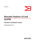
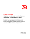
Figure 2.1 shows the FGS624P and FGS624P-POE.
Figure 2.1
FGS624P and RGS624P-POE
26
25
G
FGS-2X
The FGS624P and FGS624P-POE have the following ports:
•
24 10/100/1000 Mbps Copper ports that support 100Base-TX and 1000Base-T RJ-45 connectors
•
Four Gigabit Fiber ports for mini-GBIC optical transceivers (also called Small Form Factor Pluggable (SFP)
MultiSource Agreement (MSA)-compliant optical transceivers)
Note that ports 1 – 4 of the copper ports and 1F – 4F of the fiber ports are combination ports, meaning either
the copper port or its corresponding fiber port can be active at a time. For example, for copper port 1 and
fiber port 1F, only one of these ports can be active at any given time. The same applies to copper port 2 and
fiber port 2F, and so forth. You can use a combination of fiber and copper ports or all four copper or all four
fiber ports, as needed. For more information, see “Combination Ports” on page 2-7.
•
2-2
Optionally, two 10-GbE ports. See “10 Gbps Ports” on page 2-7.
© 2007 Foundry Networks, Inc.
September 2007
Product Overview
FGS624XGP and FGS624XGP-POE
The FGS624XGP is POE-upgradeable. You can upgrade it by installing a POE daughter card.
The FGS624XGP-POE already has the POE daughter cards installed.
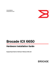
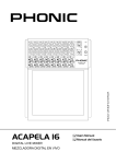
Figure 2.2 shows the FGS624XGP and FGS624XGP-POE.
Figure 2.2
FGS624XGP and FGS624XGP-POE
Slot 1
Slot 3
The FGS624XGP and FGS624XGP-POE have the following ports:
•
24 10/100/1000 Copper ports that support 100Base-TX and 1000Base-T RJ-45 connectors
•
Four Gigabit Fiber uplink ports (1F – 4F) for mini-GBIC optical transceivers (also called Small Form Factor
Pluggable (SFP) Multisource Agreement (MSA)-compliant optical transceivers)
Note that ports 1 – 4 of the copper ports and 1F – 4F of the fiber ports are combination ports, meaning either
the copper port or its corresponding fiber port can be active at a time. For example, for copper port 1 and
fiber port 1F, only one of these ports can be active at any given time. The same applies to copper port 2 and
fiber port 2F, and so forth. You can use a combination of fiber and copper ports or all four copper or all four
fiber ports, as needed. For more information, see “Combination Ports” on page 2-7.
•
One built-in 10-GbE port. See “10 Gbps Ports” on page 2-7.
•
Optionally, two additional 10-GbE ports. See “10 Gbps Ports” on page 2-7.
FGS648P and FGS648P-POE
The FGS648P is POE-upgradeable. You can upgrade it to a POE device by installing one or two POE daughter
cards. A single POE daughter card supports 24 POE ports. Two POE daughter cards support 48 POE ports.
The FGS648P-POE already has the POE daughter cards installed.
September 2007
© 2007 Foundry Networks, Inc.
2-3
FastIron GS Compact Layer 2 Switch Hardware Installation Guide
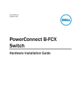
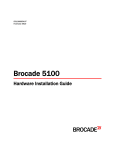
Figure 2.3 shows the FGS648P and FGS648P-POE.
Figure 2.3
FGS648P and FGS648P-POE
G
FGS-2X
The FGS648P and FGS648P-POE have the following ports:
•
48 10/100/1000 Copper ports that support 100Base-TX and 1000Base-T RJ-45 connectors
•
Four Gigabit Fiber uplink ports (1F – 4F) for mini-GBIC optical transceivers (also called Small Form Factor
Pluggable (SFP) Multisource Agreement (MSA)-compliant optical transceivers)
Note that ports 1 – 4 of the copper ports and 1F – 4F of the fiber ports are combination ports, meaning either
the copper port or its corresponding fiber port can be active at a time. For example, for copper port 1 and
fiber port 1F, only one of these ports can be active at any given time. The same applies to copper port 2 and
fiber port 2F, and so forth. You can use a combination of fiber and copper ports or all four copper or all four
fiber ports, as needed. For more information, see “Combination Ports” on page 2-7.
•
Optionally, two 10-GbE ports. See “10 Gbps Ports” on page 2-7.
Control Features
Each device’s front panel has the following control features:
•
Serial management interface (the port labeled Console)
•
Reset button
•
10/100/1000 ports with RJ-45 copper connectors
•
100/1000 ports with mini-GBIC slots for SFP MSA-compliant fiber transceivers
•
The FGS624XGP and FGS624XGP-POE have one 10-Gigabit Ethernet port for XFP MSA compliant fiber
connector(s)
•
Optionally, two 10 Gigabit Ethernet ports for XFP MSA-compliant fiber connectors
•
LEDs for ports, power supplies, and stacking1
1.Reserved for possible use in the future.
2-4
© 2007 Foundry Networks, Inc.
September 2007
Product Overview
Figure 2.4 shows the front panel of the FGS624P and FGS624P-POE.
Figure 2.4
FGS624P and FGS624P-POE Front Panel
Ports 1-4
1F
2F
3F
Stack
1 2 3 4
Console
4F
Lnk
Act
Lnk-Act
Odd
Even
PoE
5 6 7 8
PS1 PS2 Pwr
25
26
FGS-2XG
Lnk
Act
1
2
3
4
5
6
7
8
Ports 25 and 26
9
10
11
12
13
14
15
16
17
18
19
20
21
22
23
24
Ports 1-24
Figure 2.5 shows the front panel of the FGS648P and FGS648P-POE.
Figure 2.5
FGS648P and FGS648P-POE Front Panel
GbE Fiber Ports (1F - 4F)
1F
2F
3F
4F
Lnk
Act
GbE Copper Ports (1 - 48)
Stack
1 2 3 4
Console
Lnk-Act
Odd
Even
PoE
5 6 7 8
PS1 PS2 Pwr
49
50
Lnk
Act
1
2
3
4
5
6
7
8
9
10
11
12
13
14
15
16
17
18
19
20
21
22
23
24
25
26
27
28
29
30
31
32
33
34
35
36
37
38
39
40
41
42
43
44
45
46
47
48
Optional 2-port 10-GbE Module
(port 49 and 50)
Figure 2.6 shows the front panel of the FGS624XGP and FGS624XGP-POE.
Figure 2.6
FGS624XGP and FGS624XGP-POE Front Panel
GbE Fiber Ports (slot 1, ports 1F - 4F)
1F
2F
3F
4F
Lnk
Act
Console
GbE Copper Ports (slot 1, ports 1 - 24)
Stack
1 2 3 4
Lnk-Act
Odd
Even
5 6 7 8
PS1 PS2 Pwr
1
2
Lnk
Slot 2
FGS-2XG
PoE
Slot 1
Slot 3
Lnk
Act
Act
1
2
Optional 2-port 10-GbE Module
(slot 2, ports 1 and 2)
3
4
5
6
7
8
9
10
11
12
13
14
15
16
17
18
19
20
21
22
23
24
1-port 10-GbE Module
(slot 3, port 1)
Serial Management Interface (Console Port)
The serial management interface (the port labelled Console) enables you to configure and manage the device
using a third-party terminal emulation application on a directly connected PC. A straight-through EIA/TIA DB-9
serial cable (M/F) ships with the device. The serial management interface is located in the left corner of the front
panel.
September 2007
© 2007 Foundry Networks, Inc.
2-5
FastIron GS Compact Layer 2 Switch Hardware Installation Guide
Reset Button
The reset button allows you to restart the system without switching the power supplies off and on or using the CLI
or Web management interface. The button is located to the right of the serial management interface and is
recessed to prevent it from being pushed accidentally.
Network Interfaces
Table 2.1 describes the network interfaces supported on the FGS devices. For network interface specifications,
see Table 6.7 on page 6-7.
Table 2.1: Network Interfaces
Interface
Show Media
Description
1000Base-BX-D
M-GBXD
1000Base-BX-U
M-GBXU
1000Base-LHA
M-LHA
1000Base-LHB
M-LHB
1000Base-LX
M-LX
1000Base-SX
M-SX
1000Base-SX2
M-SX2
1000Base-T
C
100Base-BX
M-FBX
100Base-FX
M-FX
10GBase-ER
XG-ER
10GBase-LR
XG-LR
10GBase-SR
XG-SR
10GBase-ZR
XG-ZR
10GBase-ZRD
XG-ZRD
CX4 10GbE module
CX4
10GbE XFP and CX4 module
CX4
1310-MMF 10GbE
1310-NM
Viewing the Media Types Installed in the Ports
The output of the show media command displays the type of media (copper or fiber) installed in the ports. The
output differs between devices running software release 02.4.00 and release 02.5.00 or later. Starting in software
release 02.5.00, the software uses a stacking nomenclature.
The following shows an example of the show media output in pre-release 02.5.00.
FastIron(config)# show media
1:M-GBXD 2:M-LHB 3:M-FBX 4:M-SX2 5: C 6: C 7: C 8: C 9: C 10: C 11: C 12: C 13:
C 14: C 15: C 16: C 17: C 18: C 19: C 20: C 21: C 22: C 23: C 24: C 25:XG-ZR
1550.0 nm 26:XG-SR 27:
2-6
© 2007 Foundry Networks, Inc.
September 2007
Product Overview
The following shows an example of the show media output in release 02.5.00 and later.
FastIron(config)# show media
0/1/1:M-SX 0/1/2: C 0/1/3: C 0/1/4: C 0/1/5: C 0/1/6: C 0/1/7: C 0/1/8: C 0/1/9:
C 0/1/10: C 0/1/11: C 0/1/12: C 0/1/13: C 0/1/14: C 0/1/15: C 0/1/16: C 0/1/17:
C 0/1/18: C 0/1/19: C 0/1/20: C 0/1/21: C 0/1/22: C 0/1/23: C 0/1/24: C
0/2/1:XG-LMR 0/2/2:1310-NM
The “Show Media Description” column in Table 2.1 shows the text that displays in the output of the show media
command for each connector type.
10/100/1000 Mbps Ports
The 10/100/1000 copper ports use auto-sensing and auto-negotiating to determine the speed (10 Mbps, 100
Mbps, or 1000 Mbps) and mode (full-duplex or half-duplex) of the port at the other end of the link and adjust port
speed accordingly.
10/100/1000 ports on the FGS devices support RJ-45 copper connectors. The output of the show media
command displays C next to the ports that have copper connectors installed.
Gigabit copper ports on the FGS models support auto MDI/MDIX detection. For more information about this
feature, see "Configuring MDI/MDIX" in the Foundry FastIron Configuration Guide.
100/1000 Mbps Ports
The 100/1000 fiber ports (ports 1F – 4F) on the FGS devices support the SFP fiber connectors listed in Table 2.1.
Combination Ports
Ports 1 – 4 of the copper ports and 1F – 4F of the fiber ports are combination ports, meaning either the copper
port or its corresponding fiber port can be active at a time. For example, for copper port 1 and fiber port 1F, only
one of these ports can be active at any given time. The same applies to copper port 2 and fiber port 2F, and so
forth. You can use a combination of fiber and copper ports or all four copper or all four fiber ports, as needed.
If you attach both the copper and fiber connectors for a port to the network, the fiber connectors take precedence
over the copper connectors. These ports support true media automatic detection, meaning the device will select
the fiber or copper connector based on link availability. If a fiber link cannot be established, the device will select
the copper media.
10 Gbps Ports
This section describes the 10-GbE modules
1-Port 10-GbE Module
The 1-port 10-GbE module is installed in the FGS624XGP and FGS624XGP-POE (shown in Figure 2.4). This
module is factory-installed only. It is not a field-upgradeable module. This module is a 10-GbE fiber uplink for 10Gigabit Small Form Factor Pluggable (XFP) MSA-compliant optical transceiver.
Figure 2.7 shows the 1-port 10-GbE module. This port supports the 10-GbE connector types (10GBase) listed in
Table 2.1.
Figure 2.7
1-port 10-GbE Module
1 XFP port
2-port 10-GbE Module
The 2-port 10-GbE module on the FGS is optional. You can order the FGS with one of these 2-port 10-Gigabit
module installed at the factory, or you can later upgrade your device.
The following 2-port 10-Gigabit Ethernet module is supported:
•
2-port 10-GbE fiber uplinks for 10-Gigabit Small Form Factor Pluggable (XFP) MSA-compliant optical
September 2007
© 2007 Foundry Networks, Inc.
2-7
FastIron GS Compact Layer 2 Switch Hardware Installation Guide
transceivers (part number FGS-2XG).
Figure 2.8 shows the 2-port 10-GbE module. These ports support the 10-GbE connector types (10GBase) listed
in Table 2.1.
Figure 2.8
2-port 10-GbE Module
2 XFP ports
10 Gbps CX4 and XFP Ports
This section describes the 10-GbE CX4 modules.
2-port CX4 Module (Release 02.6.00)
The 2-port CX4 module on the FGS is optional. You can order the FGS with a 2-port CX4 module installed at the
factory, or you can later upgrade your device.
The following 2-port CX4 module is supported:
•
2-port CX4 uplinks for 10-Gigabit Small Form Factor Pluggable (XFP) MSA-compliant optical transceivers
(part number FGS-2XGC).
When this module is installed, the show media command returns the following display:
FGS648 Switch#sh media
0/2/1:CX4 0/2/2:CX4
2-port 10-GbE Hybrid Interface Module (Release 02.6.00)
The 2-port 10-GbE hybrid interface module contains a CX4 port and an XFP port. You can order the FGS with one
a 2-port hybrid module installed at the factory, or you can later upgrade your device.
The following 2-port 10-GbE hybrid interface module is supported:
•
2-port 10-GbE hybrid uplinks; one for a 10-Gigabit Small Form Factor Pluggable (XFP) MSA-compliant optical
transceiver and one for a 2-port CX4 10-Gigabit Small Form Factor Pluggable (XFP) MSA-compliant optical
transceiver (part number FGS-1XG1XGC).
When this module is installed, the show media command returns the following display:
FGS648 Switch#sh media
0/2/1:<depends on transceiver installed> 0/2/2:CX4
10GbE XFP Transceiver (FGS624XGP Models Only)
Release 02.6.00 introduced support for a 10GbE XFP transceiver specifically in port 1, slot 3..
The following 2-port CX4 module is supported:
•
2-port CX4 uplinks for 10-Gigabit Small Form Factor Pluggable (XFP) MSA-compliant optical transceivers
(part number FGS-2XGC).
Link and Activity LEDs on the module faceplates indicate operational status:
•
If the Lnk LED is on, the port is connected. If the Lnk LED is off, no connection exists, or the link is down.
•
If the Act LED is on or blinking, traffic is being transmitted and received on the port. If the Act LED is off, no
traffic is being transmitted or received on the port.
Figure 2.9 shows the faceplates of both modules:
2-8
© 2007 Foundry Networks, Inc.
September 2007
Product Overview
Figure 2.9
2-port CX4 10GbE Module and 10GbE and CX4 Module
Lnk Lnk
10GbE 2-port CX4 Module
Act Act
Lnk Lnk
10GbE XG and CX4 Module
Act Act
Cable Specifications for New Optics Modules
The following cable specifications apply to the CX4 ports, which are included in the new 10GbE interface modules
(FGS-2XGC and FGS-1XG1XGC):
•
Support for 802.3ak or 10 Gigabit Ethernet CX4 standard
•
Support of up to 15m in length
•
Requires latch-style receptacle or SFF-8470 plug
•
Recommended CX4 cable: Manufactured by WL Gore, part number IBN6600-15, CX4 Assembly - 26AWG
SPC 15.0m
CX4 10Gbps XFP Transceiver
This release introduces a twin-axial 10G copper CX4 XFP transceiver that can be installed in any 10G port. For a
link to operate properly, both sides must use identical CX4 transceivers.
The show media command identifies the CX4 as XG-CX4 as shown here:
FGS624P Switch#sh media
0/1/1: C 0/1/2:M-SX 0/1/3: C 0/1/4: C 0/1/5: C 0/1/6: C 0/1/7: C 0/1/8: C 0/1/9:
C 0/1/10: C 0/1/11: C 0/1/12: C 0/1/13: C 0/1/14: C 0/1/15: C 0/1/16: C 0/1/17:
C 0/1/18: C 0/1/19: C 0/1/20: C 0/1/21: C 0/1/22: C 0/1/23: C 0/1/24: C
0/2/1:XG-SR 0/2/2:XG-SR 0/3/1:XG-CX4
The CX4 transceiver requires a 15 meter CX4-grade cable, which may be purchased from Foundry Networks.
Refer to part number CAB-CX4-0050 when ordering.
Figure 2.10 shows the CX4 transceiver. Figure 2.11 shows the CX4-grade cable.
Figure 2.10
September 2007
CX4 Transceiver
© 2007 Foundry Networks, Inc.
2-9
FastIron GS Compact Layer 2 Switch Hardware Installation Guide
Figure 2.11
CX4 Transceiver Cable
CX4 Transceiver Infiniband cable
LEDs for Network Interfaces and Power Supplies
The fiber and copper ports on the FGS provide status information using the LEDs listed in Table 2.2.
•
The 10/100/1000 copper ports (1 – 24 or 1 – 48) use the LEDs located on the top left and top right of the
upper copper connectors. The LEDs are combined Link/Activity (Lnk/Act) LEDs. The LED on the left side is
for the upper copper connector. The LED on the right side is for the lower copper connector.
•
The 100/1000 fiber ports (1F – 4F) use the LEDs located beneath the fiber connectors. The LEDs are
combined Link/Activity (Lnk/Act) LEDs.
•
The POE ports (1 – 24) use the round LEDs located beneath the copper ports. The first (left-most) LED is for
port 1, the second LED is for port 2, the third LED is for port 3, and so forth.
•
The 10 Gbps fiber ports use the LEDs located beside them.
•
The FastIron GS with stacking1 use the Stack LEDs (1 – 8) located to the right of the console port.
•
The power supplies use the Pwr, PS1, and PS2 LEDs on the left side of the front panel, beneath the console
port.
Table 2.2: LEDs
LED
Position
State
Meaning
On
The link is up.
Off
The link is down.
Blinking
The port is transmitting and/or receiving
traffic
10/100/1000 Copper Port LEDs
Lnk/Act
Located along
the top of the
copper ports
Left for upper
copper
connector
Right for lower
copper
connector
100/1000 Fiber Port LEDs
1.Reserved for possible use in the future.
2 - 10
© 2007 Foundry Networks, Inc.
September 2007
Product Overview
Table 2.2: LEDs (Continued)
LED
Position
State
Meaning
Lnk/Act
Bottom left
On
The link is up.
Off
The link is down.
Blinking
The port is transmitting and/or receiving
traffic.
On
The port is connected.
Off
No fiber port connection exists or the link
is down.
On or Blinking
Traffic is being transmitted and/or received
on the fiber port.
Off
No traffic is being transmitted or received
on the fiber port.
Located along
the bottom of
the copper ports
On (Green)
The port is enabled, a power-consuming
device has been detected, and the
module is supplying power to the device.
Left for upper
port
Off
The port is not providing in-line power.
Right-most LED
beneath the
console port
On
The device is powered on and has enough
power to operate.
Off
The device is not powered on, or has
been powered on but does not have
sufficient power to operate.
Left-most LED
beneath the
console port
On
Power supply 1 is installed and is
functioning normally. Power supply 1 is
located in the right-hand bay (when you
are facing the rear of the device).
Off
Power supply 1 is not installed or is not
providing power.
On
Power supply 2 is installed and is
functioning normally. Power supply 2 is
located in the left-hand bay (when you are
facing the rear of the device).
Off
Power supply 2 is not installed or is not
providing power.
10 Gbps Port LEDs
Lnk
Located beside
the 10-GbE
port.
This is the topmost LED.
Act
Located beside
the 10-GbE
port.
This is the
bottom-most
LED.
POE Port LEDs
POE
Right for lower
port
Power Supply LEDs
Power
PS1
PS2
September 2007
Middle LED
beneath the
console port
© 2007 Foundry Networks, Inc.
2 - 11
FastIron GS Compact Layer 2 Switch Hardware Installation Guide
Table 2.2: LEDs (Continued)
LED
Position
State
Meaning
Stacking LEDs
Reserved for future
use
Fiber Optic Modules
Table 6.7 in the chapter “Hardware Specifications” lists the types of fiber optic modules (SFPs and XFPs)
supported on Foundry’s FGS devices.
Table 2.1 lists the description that displays in the output of the show media command for each media type.
Power Supplies
Each FGS device comes with one alternating-current (AC) power supply (part number RPS-FGS) or direct-current
(DC) power supply (part number RPSDC-FGS), depending on how it was ordered from the factory. All models
have two power supply slots, enabling you to install a second power supply for redundancy (if applicable) or for
additional POE power. You can use any combination of AC and DC supplies in the same device.
Figure 2.12 shows the AC power supply used with the FastIron GS.
Figure 2.12
RPS-FGS AC power supply
Figure 2.13 shows the DC power supply used with the FastIron GS.
Figure 2.13
RPSDC-FGS DC power supply
The power supplies are auto-sensing and auto-switching. The supplies provide 600 watts of total output power,
including +12VDC @ 10A to the system and -48VDC@ 10A for Power over Ethernet applications. The supplies
provide 100-240 VAC input, 50-60Hz @ 8A to 3.2A.
The power supplies can be swapped in or out of the device while the device is running. You can remove and insert
a power supply without opening the chassis. If the device contains redundant power supplies, you can remove
2 - 12
© 2007 Foundry Networks, Inc.
September 2007
Product Overview
one of the supplies without interrupting operation. The remaining redundant supply provides enough power for all
the ports.
For power supply hardware specifications, see “Hardware Specifications” on page 6-1.
NOTE: A FastIron GS POE device with dual power supplies may not provide redundancy, depending on how
much power the POE ports are consuming. See “Power Specifications for POE” on page 2-13.
CAUTION: Remove the power cord from a power supply before you install it in or remove it from the device.
Otherwise, the power supply or the device could be damaged as a result. (The device can be running while a
power supply is being installed or removed, but the power supply itself should not be connected to a power
source.)
CAUTION: The FGS power supply is designed exclusively for use with the FGS devices. The power supply produces extensive power to support 802.3af applications. Installing the power supply in a device other than the FGS
will cause extensive damage to your equipment.
Power Specifications for POE
The actual implementation of the 802.3af standard limits power to 15.4W (44V to 57V) from the power sourcing
device. This is in compliance with safety standards and existing wiring limitations. Though limited by the 802.3af
standard, 15.4 watts of power is ample, as most powered devices consume an average of 5 to 12 watts of power.
IP phones, wireless LAN access points, and network surveillance cameras each consume an average of 3.5 to 9
watts of power.
Foundry’s 48-volt power supplies provide power to the POE daughter card, and ultimately to POE powerconsuming devices. The number of POE power-consuming devices that one 48-volt power supply can support
depends on the number of watts required by each power-consuming device. Each 48-volt power supply provides
480 watts of power for POE, and each POE port supports a maximum of 15.4 watts of power per POE powerconsuming device. For example, if each POE power-consuming device attached to the FastIron GS consumes 12
watts of power, one 48-volt supply will power up to 40 POE ports. You can install a second 48-volt supply for
additional POE power.
NOTE: If your FastIron GS POE chassis has 48 ports and only one power supply, and each POE-enabled port
needs 15.4 watts, then a maximum of 31 ports can supply power to connected devices.
For power supply specifications, see “Hardware Specifications” on page 6-1. For POE configuration procedures,
see the Foundry FastIron Configuration Guide.
Precautions
The following precautions apply to the FastIron GS POE with 48 ports:
•
If your FastIron GS POE chassis has 48 ports and two power supplies, and the POE ports are consuming
more than 480 watts of power, a single power supply failure will cause both power supplies to shut down.
•
If your FastIron GS POE chassis has 48 ports and only one power supply, and the power consuming devices
connected to POE-enabled ports consume a total of more than 480 watts of power, the power supply may
shut down.
Cooling System and Fans
The FGS chassis has two single-speed fans that operate simultaneously. If one fan fails, it does not affect the
operation of the other fan.
September 2007
© 2007 Foundry Networks, Inc.
2 - 13
FastIron GS Compact Layer 2 Switch Hardware Installation Guide
2 - 14
© 2007 Foundry Networks, Inc.
September 2007
Chapter 3
Installing the FastIron GS Chassis
WARNING: The procedures in this manual are for qualified service personnel.
This chapter describes how to physically install the FastIron GS.
This chapter contains the following information:
•
“Unpacking a System” on page 3-1
•
“Summary of Installation Tasks” on page 3-2
•
“Installation Precautions” on page 3-3
•
“Installing an Additional Power Supply” on page 3-5
•
“Installing the Device” on page 3-11
•
“Powering On the System” on page 3-14
•
“Verifying Proper Operation” on page 3-15
•
“Attaching a PC or Terminal” on page 3-16
Information about configuring IP addresses and connecting network devices is in the chapter “Connecting
Network Devices and Checking Connectivity” on page 4-1.
Unpacking a System
Foundry systems ship with all of the following items. Please review the list below and verify the contents. If any
items are missing, please contact the place of purchase.
Package Contents
•
Foundry Networks FastIron GS POE or POE-upgradeable device with one AC or DC power supply installed
•
115V AC power cable (for AC sourced devices)
•
Rack mount brackets and mounting screws
•
CD-ROM containing software images and the user documentation (including this guide)
•
Warranty card
General Requirements
To manage the system, you need the following items for serial connection to the switch or router:
September 2007
© 2007 Foundry Networks, Inc.
3-1
FastIron GS Compact Layer 2 Switch Hardware Installation Guide
•
A management station, such as a PC running a terminal emulation application.
•
A straight-through EIA/TIA DB-9 serial cable (F/F). This cable can be ordered separately from Foundry
Networks. If you prefer to build your own cable, see the pinout information in “Attaching a PC or Terminal” on
page 3-16.
You use the serial connection to perform basic configuration tasks such as assigning an IP address and network
mask to the system. This information is required for managing the system using the Web management interface
or IronView Network Manager, or using the CLI through Telnet.
Summary of Installation Tasks
Follow the steps listed below to install your FGS device. Details for each of these steps are provided in this
chapter and in the following chapter.
Table 3.1: Summary of Installation Tasks
Task
No.
Task
Where to Find More Information
1
Ensure that the physical environment that will host the
device has the proper cabling and ventilation.
“Preparing the Installation Site” on page 3-5
2
Optionally insert an additional power supply. If you need to
install a power supply, it may be easier to install it before
mounting the device, although power supplies are “hot
swappable”, and can be installed or removed after the
device is mounted and powered-on.
“Installing an Additional Power Supply” on
page 3-5
CAUTION: Remove the power cord from a power
supply before you install or remove it from the device.
Otherwise, the power supply or the device could be
damaged. (The device can be running while a power
supply is installed or removed, but the power supply
itself must be disconnected from the power source.)
4
Install the Foundry device on a desktop, in an equipment
rack, or on the wall.
“Installing the Device” on page 3-11
5
When the device is installed, plug the power cord into a
nearby power source that adheres to the regulatory
requirements outlined in this manual.
“Powering On the System” on page 3-14
6
Verify that the system LEDs are registering the proper LED
state after power-on of the system.
“Verifying Proper Operation” on page 3-15
7
Attach a terminal or PC to the Foundry device. This
enables you to configure the device via the Command Line
Interface (CLI).
“Attaching a PC or Terminal” on page 3-16
8
No default password is assigned to the CLI. For additional
access security, assign a password.
“Assigning Permanent Passwords” on
page 4-1
9
Before attaching equipment to the device, you must
configure an interface IP address to the subnet on which it
will be located. Initial IP address configuration is performed
using the CLI with a direct serial connection. Subsequent
IP address configuration can be performed using the Web
management interface.
“Configuring IP Addresses” on page 4-3
3-2
© 2007 Foundry Networks, Inc.
September 2007
Installing the FastIron GS Chassis
Table 3.1: Summary of Installation Tasks (Continued)
Task
No.
Task
Where to Find More Information
10
Once you power on the device and assign IP addresses,
the system is ready to accept network equipment.
“Connecting Network Devices” on page 4-4
11
Test IP connectivity by pinging other devices and tracing
routes.
“Testing Connectivity” on page 4-6
12
Continue configuration using the CLI or the Web
management interface. You also can use IronView Network
Manager to manage the device. See the Foundry IronView
Network Management User’s Guide for information.
Foundry FastIron Configuration Guide
13
Secure access to the device.
Foundry FastIron Configuration Guide.
Installation Precautions
Follow these precautions when installing a Foundry device.
General Precautions
WARNING: All fiber-optic interfaces use Class 1 lasers.
CAUTION: Do not install the device in an environment where the operating ambient temperature might exceed
40o C (104o F).
CAUTION:
Make sure the air flow around the front, sides, and back of the device is not restricted.
CAUTION:
Never leave tools inside the chassis.
Lifting Precautions
WARNING: Make sure the rack or cabinet housing the device is adequately secured to prevent it from becoming
unstable or falling over.
WARNING: Do not use the handles on the power supply units to lift or carry a Foundry device.
WARNING: Mount the devices you install in a rack or cabinet as low as possible. Place the heaviest device at
the bottom and progressively place lighter devices above.
September 2007
© 2007 Foundry Networks, Inc.
3-3
FastIron GS Compact Layer 2 Switch Hardware Installation Guide
Power Supply Precautions
The following precautions apply to FastIron GS POE 48-port devices:
•
If your FastIron GS POE chassis has 48 ports and only one power supply, and each POE-enabled port needs
15.4 watts, then a maximum of 31 ports can supply power to connected devices.
•
If your FastIron GS POE chassis has 48 ports and two power supplies, and the POE ports are consuming
more than 480 watts of power, a single power supply failure will cause both power supplies to shut down.
•
If your FastIron GS POE chassis has 48 ports and only one power supply, and the power consuming devices
connected to POE-enabled ports consume a total of more than 480 watts of power, the power supply may
shut down.
CAUTION: Use a separate branch circuit for each AC power cord, which provides redundancy in case one of the
circuits fails.
CAUTION: Ensure that the device does not overload the power circuits, wiring, and over-current protection. To
determine the possibility of overloading the supply circuits, add the ampere (amp) ratings of all devices installed
on the same circuit as the device. Compare this total with the rating limit for the circuit. The maximum ampere ratings are usually printed on the devices near the input power connectors.
CAUTION: All devices with DC power supplies are intended for installation in restricted access areas only. A
restricted access area is where access can be gained only by service personnel through the use of a special tool,
lock and key, or other means of security, and is controlled by the authority responsible for the location.
CAUTION: For a DC system (DC power supply part number RPSDC-FGS), use a grounding wire of at least 10
American Wire Gauge (AWG). The 10 AWG wire should be attached to an agency-approved crimp connector,
crimped with the proper tool.
CAUTION: For the DC input circuit to the system (DC power supply part number RPSDC-FGS), make sure
there is a Listed 30 amp circuit breaker, minimum -48Vdc, double pole, on the input to the terminal block. The
input wiring for connection to the product should be Listed copper wire, 10 AWG, marked VW-1, and rated minimum 90 degrees celcius.
CAUTION: Make sure you insert the power supply right-side up. It is possible to insert the supply upside down,
although the supply will not engage with the power backplane when upside down. The power supply is right-side
up when the power connector is on the left and the fan vent is on the right.
CAUTION: Remove the power cord from a power supply before you install it in or remove it from the device.
Otherwise, the power supply or the device could be damaged as a result. (The device can be running while a
power supply is being installed or removed, but the power supply itself should not be connected to a power
source.)
CAUTION: The FGS power supply is designed exclusively for use with the FGS devices. The power supply produces extensive power to support 802.3af applications. Installing the power supply in a device other than the FGS
will cause extensive damage to your equipment.
WARNING: Disconnect the power cord from all power sources to completely remove power from the device.
WARNING: Make sure to choose the appropriate circuit device depending on the number of AC power supplies
installed in the chassis. The minimum current draw for the system is one AC power supply.
3-4
© 2007 Foundry Networks, Inc.
September 2007
Installing the FastIron GS Chassis
WARNING: Power supplies are hot swappable. However, Foundry Networks recommends that you disconnect
the power supply from AC power before installing or removing the supply. The device can be running while a
power supply is being installed or removed, but the power supply itself should not be connected to a power source.
Otherwise, you could be injured or the power supply or other parts of the device could be damaged.
WARNING: Make sure that the power source circuits are properly grounded, then use the power cord supplied
with the device to connect it to the power source.
WARNING: If the installation requires a different power cord than the one supplied with the device, make sure
you use a power cord displaying the mark of the safety agency that defines the regulations for power cords in your
country. The mark is your assurance that the power cord can be used safely with the device.
Preparing the Installation Site
Cabling Infrastructure
Ensure that the proper cabling is installed in the site. See “Chassis Specifications” on page 6-2 or
www.foundrynetworks.com for a summary of supported cabling types and their specifications.
Installation Location
Before installing the device, plan its location and orientation relative to other devices and equipment. Allow at
least 3" of space at the front of the device for the twisted-pair, fiber-optic, and power cabling. Also, allow a
minimum of 3" of space between the sides and the back of the device and walls or other obstructions.
Installing an Additional Power Supply
The FGS ships with one AC or DC power supply. If desired, you can install a second supply for added power or for
redundancy (if applicable). The illustration below shows the rear panel of an AC power supply.
If you need to install a second power supply, it may be easier to install it before mounting the device, although the
power supplies are “hot swappable” and can be installed or removed after the device is mounted and powered on.
CAUTION: Remove the power cord from a power supply before you install it in or remove it from the device.
Otherwise, the power supply or the device could be damaged. The device can be running while a power supply is
being installed or removed, but the power supply itself should be disconnected from the power source.
This section provides the following procedures:
•
“Installing an AC Power Supply” on page 3-6
•
“Installing a DC Power Supply” on page 3-8
September 2007
© 2007 Foundry Networks, Inc.
3-5
FastIron GS Compact Layer 2 Switch Hardware Installation Guide
You will need the following tools to perform these procedures:
•
#2 Phillips-head screwdriver
Installing an AC Power Supply
WARNING: Before beginning the installation, see the precautions in “Power Supply Precautions” on page 3-4.
Use the following procedures for installing AC power supplies in the FastIron GS.
To install an AC power supply, do the following:
1.
If necessary, remove the power supply locking screw located in the center rear of the device (illustrated
below).
2.
If the empty power supply bay has a cover plate, press inward on the two latches near the left and right edges
of the cover plate to unlock the plate (illustrated below), then remove the plate.
Power supply
locking screw
Latches
3.
3-6
Remove the new power supply from its packaging.
© 2007 Foundry Networks, Inc.
September 2007
Installing the FastIron GS Chassis
4.
With one hand, hold the bar on the front panel of the power supply. With the other hand, support the
underside of the power supply, and insert the power supply into the empty power supply slot. Press until the
supply is completely in the slot, so that the connectors on the back of the supply fully engage with the pins on
the power backplane.
CAUTION: Make sure you insert the power supply right-side up. It is possible to insert the supply upside down,
although the supply will not engage with the power backplane when upside down. The power supply is right-side
up when the power connector is on the left and the fan vent is on the right.
5.
Press the two latches near the edges of the supply outward to lock the supply in place.
6.
Replace the power supply locking screw.
7.
Install the power cord, as shown below.
Retaining Bale
September 2007
AC Power Cord
© 2007 Foundry Networks, Inc.
3-7
FastIron GS Compact Layer 2 Switch Hardware Installation Guide
Installing a DC Power Supply
Use the following procedures for installing DC power supplies in the FastIron GS. The following illustration shows
the front panel of a DC power supply.
WARNING: Before beginning the installation, see the precautions in “Power Supply Precautions” on page 3-4.
1.
If necessary, before installing a power supply, remove the power supply locking screw located in the center
rear of the device (illustrated below on an AC chassis).
Power supply
locking screw
Latches
3-8
2.
If the empty power supply bay has a cover plate, unlock it by pressing inward on the two latches near the left
and right edges of the cover plate (illustrated above), then remove the plate.
3.
Remove the new power supply from its packaging.
4.
Prepare the positive, negative, and ground wires by stripping about 1/4" of insulation off the end of each one.
(Use 10 AWG wire.)
5.
Loosen the three screws used to hold the wires in the connectors. These are located under the following
markings and shown in the illustration below:
© 2007 Foundry Networks, Inc.
September 2007
Installing the FastIron GS Chassis
Ground screw
Negative terminal screw
Handle
Positive terminal screw
NOTE: The handle on the front panel of the power supply may block access to the negative and positive
terminal screws. You may need to temporarily remove the receptacle for the positive and negative terminals if
you can’t access the screws used to hold the wires in the connectors. The figure below shows the screws that
secure the receptacle to the power supply.
6.
With one hand, hold the handle on the front panel of the power supply. With the other hand, support the
underside of the power supply, and insert the power supply into the empty power supply slot. Press until the
supply is completely in the slot, so that the connectors on the back of the supply are fully engaged with the
pins on the power backplane.
CAUTION: Make sure you insert the power supply right-side up. It is possible to insert the supply upside
down, although the supply will not engage with the power backplane when upside down. The power supply is
right-side up when the power connector is on the left and the fan vent is on the right.
September 2007
© 2007 Foundry Networks, Inc.
3-9
FastIron GS Compact Layer 2 Switch Hardware Installation Guide
DC Power Supply
Plug on rear of
power supply
engages connector
7.
Press the two latches near the edges of the supply outward to lock the supply in place.
8.
If you removed the receptacle for the positive and negative terminals, re-position it and secure the two screws.
9.
Connect the ground, positive and negative wires as follows:
•
Slip the ground wire into the opening under the
marking until the wire is fully in place, then use the
crimper to crimp the lug snugly onto the wire. Gently pull the lug away from the wire to verify that the lug
is securely fastened.
•
Connect the -48 VDC lead to the negative (—) terminal and tighten the negative terminal screw.
•
Connect the 48 RTN lead to the positive (+) terminal and tighten the positive terminal screw.
The following illustration shows how to connect the wires on a DC power supply.
–
Ground
+
10. Pull gently on each wire to make sure it is securely fastened in the connector.
3 - 10
© 2007 Foundry Networks, Inc.
September 2007
Installing the FastIron GS Chassis
11. Replace the power supply locking screw.
Installing the Device
You can install Foundry systems on a desktop, in an equipment rack, or on a wall.
WARNING: Make sure the rack or cabinet housing the device is adequately secured to prevent it from becoming
unstable or falling over.
WARNING: Mount the devices you install in a rack or cabinet as low as possible. Place the heaviest device at the
bottom and progressively place lighter devices above.
Desktop Installation
1.
Set the device on a flat desktop, table, or shelf. Make sure that adequate ventilation is provided for the
system – a 3-inch clearance is recommended on each side.
2.
Proceed to “Powering On the System” on page 3-14.
Rack Mount Installation
For rack mount installation, Foundry recommends that you use a Telco equipment rack.
The Foundry FastIron device supports two different rack mount kits; a kit with short mounting brackets which ships
with the device, and a kit with long mounting brackets (19 inches), which you can order separately from Foundry
Networks (part number 70166-000). Use the long mounting brackets to prevent the Foundry device from sagging
when installed in a non-compliant (non-Telco) equipment rack.
In addition to the rack mount kit, you will need the following tools for installation:
•
#2 Phillips-head screwdriver
•
Four 12-24 screws to mount the Foundry device to the rack.
WARNING: Make sure the rack or cabinet housing the device is adequately secured to prevent it from becoming
unstable or falling over.
WARNING: Mount the devices you install in a rack or cabinet as low as possible. Place the heaviest device at the
bottom and progressively place lighter devices above.
To install the rack mount brackets and mount the device in a rack, do the following:
1.
Remove the rack mount kit from the shipping carton. The kit contains two mounting brackets and several
mounting screws.
2.
Align the brackets with the screw holes on the sides of the device, then use the screws to attach the mounting
brackets. Refer to the appropriate illustration, depending on which brackets you are installing:
•
Figure 3.1 shows how to attach the short mounting brackets.
•
Figure 3.2 shows how to attach the long mounting brackets.
September 2007
© 2007 Foundry Networks, Inc.
3 - 11
FastIron GS Compact Layer 2 Switch Hardware Installation Guide
Figure 3.1
Attaching the Short Mounting Brackets
Figure 3.2
Attaching the Long Mounting Brackets
3 - 12
© 2007 Foundry Networks, Inc.
September 2007
Installing the FastIron GS Chassis
3.
Mount the device in the rack as illustrated in Figure 3.3.
NOTE: Although Figure 3.3 shows a device with short mounting brackets, the procedure for securing a
device with long mounting brackets is the same.
Figure 3.3
4.
Installing the device in a rack
Proceed to “Powering On the System” on page 3-14.
Wall Mount Installation
To mount the device on a wall, you must order and install the Wall Mount Bracket kit (part number 70076-000).
In addition to the Wall Mount Bracket kit, you will need the following tools for installation:
•
#2 Phillips-head screwdriver
•
4 #10 screws (for mounting the Foundry device on a wall)
•
1/2" thick plywood sheet if you are mounting the device on a wallboard and there are no studs on which to
mount the device.
Installing the Brackets and Mounting the Device
Follow these instructions to install the brackets and mount the Foundry device on a wall.
1.
Using the screws supplied in the kit, attach the mounting brackets to the sides of the device, as illustrated in
Figure 3.4.
September 2007
© 2007 Foundry Networks, Inc.
3 - 13
FastIron GS Compact Layer 2 Switch Hardware Installation Guide
Figure 3.4
Installing the Brackets
Powe
r
PS1
PS2
1
2
Cons
ole
25C
26C
25F
Lnk/
Act
Lnk/
Act
Lnk
FDX
FDX
26F
13
14
Act
2.
If there are no studs on which to mount the device, install 1/2" thick plywood to the wallboard or mounting
surface.
3.
Mount the device on the wall or plywood as illustrated in Figure 3.5.
NOTE: The kit does not come with screws for mounting the device to the wall. Use #10 screws to ensure proper
fit with the wall mount brackets.
NOTE: First install the top two screws on the wall, then slide the brackets onto the screws using the keyholes
located at the top of the brackets. After mounting the device, affix the bottom two screws.
Figure 3.5
Mounting the Foundry device
1. Install top screws
2. Install device
4.
3. Install bottom screws
Proceed to “Powering On the System” .
Powering On the System
Note the following before powering on the system:
•
The socket should be installed near the equipment and should be easily accessible.
•
If the outlet is not rated 115/120V, stop and get the appropriate cable for the outlet.
•
If your installation requires a different power cord than that supplied with the device, make sure you obtain a
power cord displaying the mark of the safety agency that defines the regulations for power cords in your
country. The mark is your assurance that the power cord can be used safely with the device.
3 - 14
© 2007 Foundry Networks, Inc.
September 2007
Installing the FastIron GS Chassis
After you complete the physical installation of the system, you can power on the system.
1.
Ensure that all power supplies are fully and properly inserted and no power supply slots are uncovered.
CAUTION: Never leave tools inside the device.
2.
For DC supplies, connect the power source to the wires to activate the circuit.
3.
For AC supplies:
•
Remove the power cord from the shipping package.
•
Attach the AC power cable to the AC connector on the rear panel as shown below.
Retaining Bale
AC Power Cord
•
Insert the power cable plug into a properly grounded 115V/120V electrical outlet.
•
Turn the power switch to the ON position.
4.
If your device has more than one power supply installed, repeat this procedure for each power supply.
5.
Verify the device is working properly as instructed in “Verifying Proper Operation” on page 3-15.
Powering Off the System
•
To turn an AC system OFF, press the power supply switch to the OFF position or unplug the power cords.
•
To turn a DC system OFF, disconnect the power source to the wires to de-activate the circuit.
Verifying Proper Operation
After you have installed any additional power supplies and powered on the system, verify that the device is
working properly:
1.
Verify that the LED for each power supply is a solid green.
2.
Verify proper operation by observing the LEDs:
All port LEDs should flash momentarily, usually in sequence, while the device performs diagnostics. After the
diagnostics are complete, the LEDs will be dark except for those that are attached by cables to other devices.
If the links on these cables are good and the connected device is powered on, the link LEDs will light.
Table 3.2 provides more details on specific LED conditions after system start-up.
September 2007
© 2007 Foundry Networks, Inc.
3 - 15
FastIron GS Compact Layer 2 Switch Hardware Installation Guide
Observing the Power Status LEDs
Table 3.2 lists the LEDs on the front panel of the FastIron GS that show power status. The power supplies
themselves do not have LEDs.
Table 3.2: LEDs for Power
LED
Position
State
Meaning
Pwr (Power)
Right-most LED
beneath the
Console port
On
The device is powered on and has enough
power to operate.
Off
The device is not powered on, or has
been powered on but does not have
sufficient power to operate.
Left-most LED
beneath the
Console port
On
Power supply 1 is installed and is
functioning normally. Power supply 1 is
located in the right-hand bay (when you
are facing the rear of the device).
Off
Power supply 1 is not installed or is not
providing power.
On
Power supply 2 is installed and is
functioning normally. Power supply 2 is
located in the left-hand bay (when you are
facing the rear of the device).
Off
Power supply 2 is not installed or is not
providing power.
PS1
PS2
Middle LED
beneath the
Console port
The software regularly polls the hardware for power status information. You can display the status information
from any management session using the CLI command show chassis. In addition, the software automatically
generates a Syslog message and SNMP trap if a status change occurs.
Attaching a PC or Terminal
To assign an IP address, you must have access to the Command Line Interface (CLI). The CLI is a text-based
interface that can be accessed through a direct serial connection to the device and through Telnet connections.
You need to assign an IP address using the CLI. You can access the CLI by attaching a serial cable to the
Console port. After you assign an IP address, you can access the system through Telnet, the Web management
interface, or IronView Network Manager.
To attach a management station using the serial port:
1.
Connect a PC or terminal to the serial port of the system using a straight-through cable. The serial port has a
male DB-9 connector.
NOTE: You need to run a terminal emulation program on the PC.
2.
3 - 16
Open the terminal emulation program and set the session parameters as follows:
•
Baud: 9600 bps
•
Data bits: 8
•
Parity: None
•
Stop bits: 1
© 2007 Foundry Networks, Inc.
September 2007
Installing the FastIron GS Chassis
•
Flow control: None
When you establish the serial connection to the system, press Enter to display the CLI prompt in the terminal
emulation window. For example:
•
FastIron>
•
FastIron-PREM>
If you see one of these prompts, you are now connected to the system and can proceed to “Assigning Permanent
Passwords” on page 4-1.
You can customize the prompt by changing the system name. See the Foundry FastIron Configuration Guide.
If you do not see one of these prompts:
1.
Make sure the cable is securely connected to your PC and to the Foundry system.
2.
Check the settings in your terminal emulation program. In addition to the session settings listed above, make
sure the terminal emulation session is running on the same serial port you attached to the Foundry system.
The EIA/TIA 232 serial communication port serves as a connection point for management by a PC or SNMP
workstation. Foundry switches and Layer 3 Switches come with a standard male DB-9 connector, shown in Figure
3.6.
Figure 3.6
Serial port pin and signalling details
Pin Assignment
DB-9 male
1
6
Pin Number
Switch Signal
1
2
3
4
5
6
7
8
9
Reserved
TXD (output)
RXD (input)
Reserved
GND
Reserved
CTS (input)
RTS (output)
Reserved
5
9
Most PC serial ports also require a cable with a female DB-9 connector.
Terminal connections will vary, requiring either a DB-9 or DB-25 connector, male or female.
Serial cable options between a Foundry switch or router and a PC or terminal are shown in Figure 3.7.
NOTE: As indicated in Figure 3.6 and Figure 3.7, some of the wires should not be connected. If you do connect
the wires that are labeled “Reserved”, you might get unexpected results with some terminals.
September 2007
© 2007 Foundry Networks, Inc.
3 - 17
FastIron GS Compact Layer 2 Switch Hardware Installation Guide
Figure 3.7
Serial port pin assignments showing cable connection options to a terminal or PC
Terminal or PC
DB-9 to DB-25
Female Switch
1
1
2
2
2
3
3
3
3
2
4
4
5
5
6
6
7
7
7
4
8
8
8
5
9
9
DB-9 to DB-9
Female Switch
1
4
Reserved
Reserved
5
6
9
3 - 18
Reserved
Reserved
© 2007 Foundry Networks, Inc.
Terminal or PC
Reserved
Reserved
8
20
7
Reserved
Reserved
6
22
September 2007
Chapter 4
Connecting Network Devices and
Checking Connectivity
WARNING: The procedures in this manual are for qualified service personnel.
This chapter provides the details for connecting network devices and checking network connectivity.
The following lists the tasks you must perform to connect your Foundry device, and shows where to get
troubleshooting information for any problems that can arise.
Table 4.1: Summary of Network Connectivity Tasks
Task
Number
Task
Where to Find More Information
1
Secure access to the CLI by assigning passwords.
“Assigning Permanent Passwords” on
page 4-1
2
Configure IP addresses for the management, Ethernet,
virtual, and loopback interfaces.
“Configuring IP Addresses” on page 4-3
3
Connect your device to another networking device.
“Connecting Network Devices” on page 4-4
4
Test a port for connectivity to other networking devices
using the ping and traceroute commands.
“Testing Connectivity” on page 4-6
5
Troubleshoot any problems that can arise.
“Troubleshooting Network Connections” on
page 4-8
Assigning Permanent Passwords
By default, the CLI is not protected by passwords. To secure CLI access, Foundry strongly recommends assigning
passwords.
NOTE: You cannot assign a password using the Web management interface. You can assign passwords using
IronView Network Manager if an enable password for a Super User has been configured on the device.
The CLI contains the following access levels:
•
User EXEC – The level you enter when you first start a CLI session. At this level, you can view some system
information but you cannot configure system or port parameters.
September 2007
© 2007 Foundry Networks, Inc.
4-1
FastIron GS Compact Layer 2 Switch Hardware Installation Guide
•
Privileged EXEC – This level is also called the Enable level and can be secured by a password. You can
perform tasks such as manage files on the flash module, save the system configuration to flash, and clear
caches at this level.
•
CONFIG – The configuration level. This level lets you configure the system’s IP address and configure
switching and routing features. To access the CONFIG mode, you must already be logged into the Privileged
level of the EXEC mode.
You can set the following levels of Enable passwords:
•
Super User – Allows complete read-and-write access to the system. This is generally for system
administrators and is the only password level that allows you to configure passwords.
NOTE: You must set a super user password before you can set other types of passwords.
•
Port Configuration – Allows read-and-write access for specific ports but not for global (system-wide)
parameters.
•
Read Only – Allows access to the Privileged EXEC mode and CONFIG mode but only with read access.
To set passwords:
1.
At the opening CLI prompt, enter the following command to change to the Privileged level of the EXEC mode:
FastIron> enable
2.
Access the CONFIG level of the CLI by entering the following command:
FastIron# configure terminal
FastIron(config)#
3.
Enter the following command to set the super-user password:
FastIron(config)# enable super-user-password <text>
NOTE: You must set the super-user password before you can set other types of passwords.
4.
Enter the following commands to set the port configuration and read-only passwords:
FastIron(config)# enable port-config-password <text>
FastIron(config)# enable read-only-password <text>
NOTE: If you forget your super-user password, see “Recovering from a Lost Password” .
Syntax: enable super-user-password | read-only-password | port-config-password <text>
Passwords can be up to 32 characters long.
Recovering from a Lost Password
By default, the CLI does not require passwords. However, if someone has configured a password for the device
but the password has been lost, you can regain super-user access to the device using the following procedure.
NOTE: Recovery from a lost password requires direct access to the serial port and a system reset.
To recover from a lost password:
4-2
1.
Start a CLI session over the serial interface to the Foundry device.
2.
Reboot the device.
3.
While the system is booting, before the initial system prompt appears, enter b to enter the boot monitor mode.
4.
Enter no password at the prompt. (You cannot abbreviate this command.)
© 2007 Foundry Networks, Inc.
September 2007
Connecting Network Devices and Checking Connectivity
5.
Enter boot system flash primary at the prompt. This command causes the device to bypass the system
password check.
6.
After the console prompt reappears, assign a new password.
Configuring IP Addresses
You must configure at least one IP address using the serial connection to the CLI before you can manage the
system using the other management interfaces. In addition, Foundry routers require an IP subnet address for the
subnet in which you plan to place them in your network.
Foundry devices support both classical IP network masks (Class A, B, and C subnet masks, and so on) and
Classless Interdomain Routing (CIDR) network prefix masks.
•
To enter a classical network mask, enter the mask in IP address format. For example, enter
“209.157.22.99 255.255.255.0” for an IP address with a Class-C subnet mask.
•
To enter a prefix number for a network mask, enter a forward slash ( / ) and the number of bits in the mask
immediately after the IP address. For example, enter “209.157.22.99/24” for an IP address that has a network
mask with 24 significant (“mask”) bits.
By default, the CLI displays network masks in classical IP address format (example: 255.255.255.0). You can
change the display to the prefix format. See the Foundry FastIron Configuration Guide.
NOTE: If your network uses a BootStrap Protocol (BootP) server or a Dynamic Host Configuration Protocol
(DHCP) server, you can allow the Foundry device to obtain IP addresses for the hosts on the network.
Devices Running Layer 2 Software
To configure an IP Address on a device running Layer 2 software:
1.
At the opening CLI prompt, enter enable.
FastIron> enable
2.
Enter the following command at the Privileged EXEC level prompt (for example, FastIron Switch#), then press
Enter. This command erases the factory test configuration if still present:
FastIron# erase startup-config
CAUTION: Use the erase startup-config command only for new systems. If you enter this command on a
system you have already configured, the command erases the configuration. If you accidentally do erase the
configuration on a configured system, enter the write memory command to save the running configuration to
the startup-config file.
3.
Access the configuration level of the CLI by entering the following command:
FastIron# configure terminal
Global CONFIG Level
FastIron(config)#
4.
Privileged EXEC Level
Configure the IP address and mask for the switch.
FastIron(config)# ip address 192.22.3.44 255.255.255.0
5.
Set a default gateway address for the switch.
FastIron(config)# ip default-gateway 192.22.3.1
NOTE: You do not need to assign a default gateway address for single subnet networks.
Syntax: enable [<password>]
Syntax: configure terminal
September 2007
© 2007 Foundry Networks, Inc.
4-3
FastIron GS Compact Layer 2 Switch Hardware Installation Guide
Syntax: [no] ip address <ip-addr> <ip-mask>
or
Syntax: [no] ip address <ip-addr>/<mask-bits>
Syntax: ip default-gateway <ip-addr>
Connecting Network Devices
Foundry devices support connections to other vendors’ routers, switches, and hubs, as well other Foundry
devices.
Cable Specifications
See “Cable Specifications” on page 6-7 for cable lengths and types supported on the FGS devices.
Connecting to Ethernet or Fast Ethernet Hubs
For copper connections to Ethernet hubs, a 10/100Base-TX or 1000Base-T switch, or another Foundry device, a
crossover cable is required (Figure 4.1 and Figure 4.2). If the hub is equipped with an uplink port, it will require a
straight-through cable instead of a crossover cable.
NOTE: The 802.3ab standard (automatic MDI/MDIX detection) calls for automatic negotiation of the connection
between two 1000Base-T ports. Therefore, a crossover cable may not be required; a straight-through cable may
work as well. For more information about this feature, see the Foundry FastIron Configuration Guide.
Figure 4.1
UTP crossover cable
UTP Crossover Cable
10/100BaseTX
1
8
1
1
2
2
3
3
unused 4
4 unused
unused 5
5 unused
6
4-4
6
unused 7
7 unused
unused 8
8 unused
© 2007 Foundry Networks, Inc.
September 2007
Connecting Network Devices and Checking Connectivity
Figure 4.2
Cat-5 crossover cable for 1000Base-T
Cat-5 Crossover Cable
1000BaseT
1
8
1
1
2
2
3
3
4
4
5
5
6
6
7
7
8
8
NOTE: The 802.3ab standard calls for automatic negotiation of the connection between two 1000Base-T ports.
Consequently, a crossover cable may not be required; a straight-through cable may work as well.
Connecting to Workstations, Servers, or Routers
Straight-through UTP cabling is required for direct UTP attachment to workstations, servers, or routers using
network interface cards (NICs).
Fiber cabling is required for direct attachment to Gigabit NICs or switches and routers via fiber ports. See
“Connecting a Network Device to a Fiber Port” on page 4-5.
Automatic MDI/MDIX Detection
All 10/100 and Gigabit Ethernet Copper ports on the Foundry FGS devices support automatic Media Dependent
Interface (MDI) and Media Dependent Interface Crossover (MDIX) detection. This feature is enabled on all 10/100
and Gigabit copper ports by default. For each port, you can disable auto MDI/MDIX, designate the port as an MDI
port, or designate the port as an MDIX port.
For more information about this feature and how configure it, see the Foundry FastIron Configuration Guide.
Connecting a Network Device to a Fiber Port
For direct attachment from the Foundry device to a Gigabit NIC, switch, or router, fiber cabling with an LC
connector is required.
To connect the Foundry device to another network device using a fiber port, you must do the following:
•
Install a fiber optic module (SFP transceiver or mini-GBIC for Gigabit Ethernet ports, or XFP-MSA transceiver
for 10-Gigabit Ethernet ports)
•
Cable the fiber optic module
The following sections provide information about performing these tasks.
Installing a Fiber Optic Module
You must install a fiber optic module (SFP or XFP transceiver) in each Gigabit Ethernet and 10-Gigabit Ethernet
fiber port you want to use.
You can install a new fiber optic module in a port while the Foundry device is powered on and running.
September 2007
© 2007 Foundry Networks, Inc.
4-5
FastIron GS Compact Layer 2 Switch Hardware Installation Guide
To install a fiber optic module, you will need an ESD wrist strap with a plug for connection to a metal surface.
WARNING: For safety reasons, the ESD wrist strap should contain a series 1 meg ohm resistor.
To install a fiber optic module, do the following:
1.
Put on the ESD wrist strap and ground yourself by attaching the clip end to a metal surface (such as an
equipment rack) to act as ground.
2.
Remove the new module from its protective packaging.
3.
Gently insert the fiber optic module into the port until the module clicks into place. The module is keyed to
prevent incorrect insertion.
Cabling a Fiber Optic Module
To cable a fiber optic module, do the following:
1.
Remove the protective covering from the fiber-optic port connectors and store the covering for future use.
2.
Before cabling a fiber optic module, Foundry strongly recommends cleaning the cable connectors and the
port connectors. For more information, see “Cleaning the Fiber-Optic Connectors” on page 4-6.
3.
Gently insert the cable connector(s) (a tab on each connector should face upward) into the port connector(s)
until the tabs lock into place.
4.
Observe the link and active LEDs to determine if the network connections are functioning properly. See Table
4.2 on page 4-7.
Cleaning the Fiber-Optic Connectors
To avoid problems with the connection between the fiber optic module (SFP (mini-GBIC) or XFP) and the fiber
cable connectors, Foundry strongly recommends cleaning both connectors each time you disconnect and
reconnect them. In particular, dust can accumulate in the connectors and cause problems such as reducing the
optic launch power.
To clean the fiber cable connectors, Foundry recommends using the fiber-optic reel-type cleaner that shipped with
your Foundry chassis. You can also purchase this type of cleaner from the following Website:
http://www.fisfiber.com
When not using an SFP or XFP connector, make sure to keep the protective covering on.
Testing Connectivity
After you install the network cables, you can test network connectivity to other devices by pinging those devices.
You also can observe the LEDs related to network connection and perform trace routes.
Pinging an IP Address
To verify that a Foundry device can reach another device through the network, enter a command such as the
following at any level of the CLI on the Foundry device:
FastIron>ping 192.33.4.7
Syntax: ping <ip addr> | <hostname> [source <ip addr>] [count <num>] [timeout <msec>] [ttl <num>] [size <byte>]
[quiet] [numeric] [no-fragment] [verify] [data <1-to-4 byte hex>] [brief]
NOTE: If you address the ping to the IP broadcast address, the device lists the first four responses to the ping.
4-6
© 2007 Foundry Networks, Inc.
September 2007
Connecting Network Devices and Checking Connectivity
Observing LEDs
After you install the network cables, you can observe certain LEDs to determine if the network connections are
functioning properly. Table 4.2 outlines the LEDs related to the network connections, the desired state of each
LED, possible abnormal states of each LED, and what to do if an LED indicates an abnormal state.
Table 4.2: Network Connection-Related LED States
LED
Desired
State
Meaning
Abnormal
State
Meaning/Action
Link (Lnk)
On
(Green)
A link is established
with the remote port.
Off
A link is not established with the remote port.
You can do the following:
Active (Act)
On or
blinking
(Yellow)
The port is
transmitting and
receiving user
packets.
Off for an
extended
period.
•
Verify that the connection to the other
network device has been properly made.
Also, make certain that the other network
device is powered on and operating
correctly.
•
Verify that the transmit port on the
Foundry device is connected to the
receive port on the other network device,
and that the receive port on the Foundry
device is connected to the transmit port
on the other network device. If you are not
certain, remove the two cable connectors
from the port connector and reinsert them
in the port connector, reversing their
order.
•
Dust may have accumulated in the cable
connector or port connector. For
information about cleaning the
connectors, see “Cleaning the Fiber-Optic
Connectors” on page 4-6.
•
If the other actions don’t resolve the
problem, try using a different port or a
different cable.
The port is not transmitting or receiving user
packets. You can do the following:
•
Check the Link LED to make sure the link
is still established with the remote port. If
not, take the actions described in the
Meaning/Action column for the Link LED.
•
Verify that the port has not been disabled
through a configuration change. You can
use the CLI. If you have configured an IP
address on the device, you also can use
the Web management interface or
IronView Network Manager.
If a problem persists after taking these actions, contact Foundry’s technical support.
September 2007
© 2007 Foundry Networks, Inc.
4-7
FastIron GS Compact Layer 2 Switch Hardware Installation Guide
Tracing a Route
To determine the path through which a Foundry device can reach another device, enter a command such as the
following at any level of the CLI on the Foundry device:
FastIron>traceroute 192.33.4.7
Syntax: traceroute <host-ip-addr> [maxttl <value>] [minttl <value>] [numeric] [timeout <value>]
[source-ip <ip addr>]
The CLI displays trace route information for each hop as soon as the information is received. Traceroute requests
display all responses to a given TTL. In addition, if there are multiple equal-cost routes to the destination, the
Foundry device displays up to three responses by default.
Troubleshooting Network Connections
•
For the indicated port, verify that both ends of the cabling (at the Foundry device and the connected device)
are snug.
•
Verify that the Foundry device and the connected device are both powered on and operating correctly.
•
Verify that you have used the correct cable type for the connection:
•
For twisted-pair connections to an end node, use straight-through cabling.
•
For fiber-optic connections, verify that the transmit port on the device is connected to the receive port on
the connected device, and that the receive port on the device is connected to the transmit port on the
connected device.
•
Verify that the port has not been disabled through a configuration change. You can use the CLI. If you have
configured an IP address on the device, you also can use the Web management interface or IronView
Network Manager.
•
For copper ports, you can test the cable using Virtual Cable Testing. See “Using Virtual Cable Testing to
Diagnose a Cable” .
•
If the other procedures don’t resolve the problem, try using a different port or a different cable.
Using Virtual Cable Testing to Diagnose a Cable
FGS devices support Virtual Cable Test (VCT) technology. VCT technology enables you to diagnose a conductor
(wire or cable) by sending a pulsed signal into the conductor, then examining the reflection of that pulse. This
method of cable analysis is referred to as Time Domain Reflectometry (TDR). By examining the reflection, the
Foundry device can detect and report cable statistics such as local and remote link pair, cable length, and link
status.
Configuration Notes
•
This feature is supported on copper ports only. It is not supported on fiber ports.
•
The port to which the cable is connected must be enabled when you issue the command to diagnose the
cable. If the port is disabled, the command is rejected.
•
If the port is operating at 100 Mbps half-duplex, the TDR test on one pair will fail.
•
If the remote pair is set to forced 100 Mbps, any change in MDI/MDIX may cause the device to interpret the
Multilevel Threshold-3 (MLT-3) as a reflected pulse, in which case, the device will report a faulty condition. In
this case, Foundry recommends that you run the TDR test a few times for accurate results.
Command Syntax
To diagnose a cable using TDR, enter a command such as the following at the Privileged EXEC level of the CLI:
FastIron#phy cable-diag tdr 1
The above command diagnoses the cable attached to port 1.
Syntax: phy cable-diag tdr <port-num>
4-8
© 2007 Foundry Networks, Inc.
September 2007
Connecting Network Devices and Checking Connectivity
Viewing the Results of the Cable Analysis
To display the results of the cable analysis, enter a command such as the following at the Privileged EXEC level of
the CLI:
FastIron#sh cable-diag tdr 1
Port
Speed Local pair Pair Length
--------- ----- ---------- ----------01
1000M Pair A
<50M
Pair B
<50M
Pair C
<50M
Pair D
<50M
Remote pair
----------Pair B
Pair A
Pair D
Pair C
Pair status
----------Terminated
Terminated
Terminated
Terminated
Syntax: show cable-diag tdr <port-num>
Table 4.3 defines the fields shown in the command output.
Table 4.3: Cable Statistics
This Line...
Displays...
Port
The port that was tested.
Speed
The port’s current line speed.
Local pair
The local link name.
Pair Length
The cable length when terminated, or the distance to the point of fault
when the line is not up.
Remote pair
The remote link name.
Pair status
The status of the link. This field displays one of the following:
September 2007
•
Terminated: The link is up.
•
Shorted: A short is detected in the cable.
•
Open: An opening is detected in the cable.
•
ImpedMis: The impedance is mismatched.
•
Failed: The TDR test failed.
© 2007 Foundry Networks, Inc.
4-9
FastIron GS Compact Layer 2 Switch Hardware Installation Guide
4 - 10
© 2007 Foundry Networks, Inc.
September 2007
Chapter 5
Managing the FastIron GS Chassis
This chapter contains information about refining the configuration of, monitoring, and managing the following
hardware components:
•
“Managing Temperature Settings” on page 5-1
•
“Displaying Management Module CPU Usage” on page 5-3
•
“Removing MAC Address Entries” on page 5-3
Managing Temperature Settings
This section describes how to display temperature settings on the FGS chassis and how to change the
temperature warning levels.
Using the Temperature Sensor
The FastIron GS chassis comes with two built-in temperature sensors; one at the air intake, and the other at the
exhaust. The temperature sensor at the air intake monitors the incoming air temperature. The temperature sensor
at the air exhaust monitors the air temperature as it exits the device. The temperature sensors cause the device to
generate a Syslog message and SNMP trap if the temperature exceeds a specified warning level.
The software reads the temperature sensors according to the chassis poll time, which is 60 seconds by default. If
the temperature equals or exceeds the warning temperature, the software generates a Syslog message and
SNMP trap.
You can use the CLI to do the following:
•
Display the temperature of the device
•
Change the warning temperature levels
•
Change the chassis poll time
Displaying the Temperature
By default, the software polls the temperature sensor every 60 seconds to get the current temperature. This poll
rate is controlled by the chassis poll time, which also controls how often the software polls other system
components.
September 2007
© 2007 Foundry Networks, Inc.
5-1
FastIron GS Compact Layer 2 Switch Hardware Installation Guide
To display the temperature of a device, enter the show chassis command at any level of the CLI. The following
shows an example output.
FastIron>show chassis
power supply 1 <NA - AC - Regular> present, status ok
power supply 2 not present
Fan 1 ok
Fan 2 ok
Exhaust Side Temperature Readings:
Current temperature : 28.5
Warning level.......: 45.0
Shutdown level......: 55.0
Intake Side Temperature Readings:
Current temperature : 29.0
Boot Prom MAC: 00e0.5200.0100
degrees Celsius
degrees Celsius
degrees Celsius
degrees Celsius
Syntax: show chassis
Displaying Temperature Messages
The software sends a Syslog message and an SNMP trap if the temperature crosses the warning threshold. The
following methods describe how to view the system log on the device. If you have configured the device to use a
Syslog server or SNMP trap receiver, see the documentation for the server or receiver.
To display the system log, enter the following command at any CLI level:
FastIron# show log
Syslog logging: enabled (0 messages dropped, 0 flushes, 0 overruns)
Buffer logging: level ACDMEINW, 8 messages logged
level code: A=alert C=critical D=debugging M=emergency E=error
I=informational N=notification W=warning
Static Log Buffer:
Dynamic Log Buffer (50 entries):
at 0 days 0
Temperature
at 0 days 0
Temperature
hours 2 minutes
48.0 C degrees,
hours 1 minutes
50.0 C degrees,
0 seconds, level alert
warning level 45.0 C degrees
0 seconds, level alert
warning level 45.0 C degrees
Changing the Temperature Warning Level
The default warning temperature is 45.0 C degrees. You can change the warning temperature using the following
command. The valid range is 0 – 125 C degrees.
With FGS software release 03.0.00, the FGS devices automatically reset and reload the software when the
internal temperature reaches or exceeds the configured shutdown level for five minutes. This release also adds
the capability for the system to register negative temperature settings.
To change the temperature at which the device sends a warning, enter a command such as the following at the
Privileged EXEC level of the CLI:
FastIron#temperature warning 47
Syntax: temperature warning <value>
The <value> can be 0 – 125.
5-2
© 2007 Foundry Networks, Inc.
September 2007
Managing the FastIron GS Chassis
Changing the Chassis Temperature Polling Interval
The software reads the temperature sensor and polls other hardware sensors according to the value set for the
chassis poll time, which is 60 seconds by default. You can change the chassis poll time using the CLI.
To change the chassis poll time, enter a command such as the following at the global CONFIG level of the CLI:
FastIron(config)#chassis poll-time 200
Syntax: chassis poll-time <value>
The <value> can be 0 – 65535.
Displaying Management Module CPU Usage
You can display the amount of the management module’s CPU in use. To do so, enter the following command at
any level of the CLI:
FastIron# show cpu
31 percent busy,
1
sec avg: 31
5
sec avg: 31
60 sec avg: 31
300 sec avg: 31
from 3248 sec ago
percent busy
percent busy
percent busy
percent busy
Syntax: show cpu
Removing MAC Address Entries
You can remove learned MAC address entries from the Foundry system’s MAC address table. You can remove the
following entries:
•
All MAC address entries
•
All MAC address entries for a specified Ethernet port
•
All MAC address entries for a specified VLAN
•
A specified MAC address entry in all VLANs
For example, to remove entries for the MAC address 000d.cb80.00d in all VLANs, enter the following command at
the Privileged EXEC level of the CLI:
FastIron# clear mac-address 000d.cb80.00d0
Syntax: clear mac-address <mac-address> | ethernet <port-num> | vlan <number>
If you enter the clear mac-address command without any parameters, the software removes all MAC entries.
Use the <mac-address> parameter to remove a specified MAC address from all VLANs. Specify the MAC address
in the following format: HHHH.HHHH.HHHH.
Use the ethernet <port-num> parameter to remove all MAC addresses for a specified Ethernet port.
Use the vlan <number> parameter to remove all MAC addresses for a specified VLAN.
September 2007
© 2007 Foundry Networks, Inc.
5-3
FastIron GS Compact Layer 2 Switch Hardware Installation Guide
5-4
© 2007 Foundry Networks, Inc.
September 2007
Chapter 6
Hardware Specifications
This chapter contains the following hardware specifications for the Foundry Networks FastIron GS devices:
Chassis Specifications
•
“Physical Dimensions and Weight” on page 6-2
•
“Environmental Considerations” on page 6-2
•
“Cooling” on page 6-3
•
“Regulatory Compliance” on page 6-3
•
“Power Source Interruptions” on page 6-4
•
“Mean Time Between Failure” on page 6-4
•
“Pinouts and Signalling” on page 6-6
•
“Cable Specifications” on page 6-7
•
“Power Cords” on page 6-9
•
“Warranty” on page 6-9
Power Supply Specifications
•
“Overview” on page 6-9
•
“Key features” on page 6-10
•
“Physical Dimensions and Weight” on page 6-10
•
“Environmental Considerations” on page 6-10
•
“Input Connector and Plug” on page 6-12
•
Power Consumption
•
“Regulatory Compliance” on page 6-13
•
“Safety Warnings” on page 6-13
•
“Electrical Specifications” on page 6-14
September 2007
© 2007 Foundry Networks, Inc.
6-1
FastIron GS Compact Layer 2 Switch Hardware Installation Guide
Chassis Specifications
The following sections present the hardware specifications for the FastIron GS.
Physical Dimensions and Weight
Table 6.1 lists the physical dimensions and weight of the FastIron GS models.
Table 6.1: Physical Dimensions and Weight of the FGS Models
Platform
Height
Width
Depth
Weight
FGS624P
and
FGS624P-POE
2.63 in
6.68 cm
17.5 in
44.45 cm
19.6 in
49.78 cm
•
25 lbs (11.36 kg) fully loaded,
including dual redundant power
supplies
•
17.5 lbs (7.94 kg) empty
•
29 lbs (13.15 kg) fully loaded,
including dual redundant power
supplies
•
17.5 lbs (7.94 kg) empty
FGS648P and
FGS648P-POE
2.63 in
6.68 cm
17.5 in
44.45 cm
19.6 in
49.78 cm
Environmental Considerations
For optimal performance, operate or store your Foundry device in compliance with the following environmental
conditions.
Table 6.2: Environmental Conditions for the Chassis
Description
Range
Operating Environment
Operating temperature
32° – 104° F (0° – 40° C)
Operating altitude
6,600 feet maximum
Relative humidity
5 to 95%, @ 104°F (40° C), non-condensing
or
5 to 95% non-condensing for DC power
supply
Operating noise
47 – 51 dB
Maximum heat dissipation
328 BTU/Hr with 2-port 10-Gigabit uplinks
280 BTU/Hr without 2-port 10-Gigabit uplinks
Storage Environment
6-2
Storage temperature
-23° to 158° F, -25° to 70° C
Storage humidity
95% maximum, non-condensing
Storage altitude
15,000 feet (3,000 meter) maximum
© 2007 Foundry Networks, Inc.
September 2007
Hardware Specifications
Cooling
The FGS chassis has two single-speed fans that operate simultaneously. If one fan fails, it does not affect the
operation of the other fanThe cooling fans cool the CPU, main memory, and voltage regulators. The fans use
either a push or pull configuration to move the air from the left side of the device to the right side of the device as
shown in Figure 6.1.
•
Total cooling capacity: 120 watts
•
Total air flow: 80 LFM
•
Fan operating noise: < 51 dB-A.
NOTE: Operating noise is based on the ISO 7779 standard.
Figure 6.1
Internal airflow
Air exhaust
26
X4-2XG
25
Air inlet
Regulatory Compliance
Table 6.3 lists the Electromagnetic Compatibility (EMC), Immunity standards, and safety agency approvals for the
FGS family of switches.
Table 6.3: Chassis Regulatory Compliance
Description
Certifications
Electromagnetic Emissions
CISPR-22 Class A
EN 55022
FCC Class A (Part 15)
VCCI Class A
Immunity
September 2007
EN 50024:1998
© 2007 Foundry Networks, Inc.
6-3
FastIron GS Compact Layer 2 Switch Hardware Installation Guide
Table 6.3: Chassis Regulatory Compliance (Continued)
Description
Certifications
Safety
EN 60950-1
CAN/CS-C22.2 No. 60950-1
EN 60825-1, Safety of Laser Products - Part 1
EN 60825-2, Safety of Laser Products - Part 2
IEC 60950-1
UL 60950-1
Power Source Interruptions
Table 6.4 shows how the FastIron GS protects against power surges and power drops.
Table 6.4: Chassis Power Surge and Drop Protection
Property
Protection Mechanism
Power surge
MOV and Spark Gap protection
Power drop (<=1 second)
An AC loss of >15ms will cause the power supply
to shut down due to input under-voltage
Maximum power draw
96 watts with 2-port 10-Gigabit uplinks
82 watts without 2-port 10-Gigabit uplinks
Mean Time Between Failure
Table 6.5 lists the Mean Time Between Failure (MTBF) for the FastIron GS and the 10-GbE uplink modules. The
MTBF is the average estimated time, in units of hours, before a hardware failure may occur.
Table 6.5: MTBF for the FastIron GS and 10-GbE modules
Configuration / Module
Temperature
MTBF (hours)
Without POE
With POE
24-port POE ready + 4 SFPs + 2-port 10-GbE
module + 2 XFPs + 1 power supply
40o Celsius
150,879
142,217
24-port POE ready + 4 SFPs + 2-port 10-GbE
module + 2 XFPs + 2 powers supplies
40o Celsius
267,411
241,356
48-port POE ready + 4 SFPs + 2-port 10-GbE
module + 2 XFPs + 1 power supply
40o Celsius
133,825
120,775
48-port POE ready + 4 SFPs + 2-port 10-GbE
module + 2 XFPs + 2 power supplies
40o Celsius
218,140
196,401
2-port 10-GbE XFP module
40o Celsius
1,597,580
N/A
2-port 10-GbE CX4 modulea
40o Celsius
6-4
© 2007 Foundry Networks, Inc.
29,673,590
September 2007
Hardware Specifications
Table 6.5: MTBF for the FastIron GS and 10-GbE modules (Continued)
Configuration / Module
Temperature
MTBF (hours)
Without POE
With POE
1-port 10-GbE XFP + 1-port 10-GbE CX4
modulea
40o Celsius
2,364,614
1-port 10-GbE XFP module
40o Celsius
2,501,219
a.This module will be available in a future release.
Power Draw Specifications
Table 6.6 lists the typical and maximum power draw specifications for FGS models.
Table 6.6: Power Supply Draw Specifications
Model
Typical
Maximum
24-Port
•
without uplink: 3.5A @12V = 42W
•
•
with 2CX4+1XFP: 4.4A @ 12V = 53W
without uplink: 1.7A @ 12V/PS1 +
1.7A @ 12V/PS2 = 48W
•
with 2XFP+1XFP: 4.3A @ 12V = 53W
•
with 2CX4+1XFP: 2.2A @ 12V/
PS1 + 2.2A @ 12V/PS2 = 63W
•
with Combo+1XFP: 4.2A @ 12V = 53W
•
with 2XFP+1XFP: 2.1A @ 12V/
PS1 + 2.2A @ 12V/PS2 = 67W
•
with Combo+1XFP: 2.0A @ 12V/
PS1 + 2.1A @ 12V/PS2 = 65W
•
without uplink: 3.4A @ 12V/PS1 +
3.4A @ 12V/PS2 = 94W
•
with 2CX4: 3.7A @ 12V/PS1 +
3.7A @ 12V/PS2 = 102W
•
with 2XFP: 3.6A @ 12V/PS1 +
3.6A @ 12V/PS2 = 106W
•
with Combo: 3.7A @ 12V/PS1 +
3.7A @ 12V/PS2 = 104W
48-Port
September 2007
•
without uplink: 6.8A @12V = 82W
•
with 2CX4: 7.4A @12V = 89W
•
with 2XFP: 7.3A @12V = 89W
•
with Combo: 7.4A @12V= 89W
© 2007 Foundry Networks, Inc.
6-5
FastIron GS Compact Layer 2 Switch Hardware Installation Guide
Pinouts and Signalling
This section lists the pinouts for the DB-9 connector and RJ-45 port jacks.
Serial (Console) Port Pinouts
The Console port is a standard male DB-9 connector, as shown in Figure 6.2.
Figure 6.2
Serial port pin and signalling details
Pin Assignment
DB-9 male
1
6
Pin Number
Switch Signal
1
2
3
4
5
6
7
8
9
Reserved
TXD (output)
RXD (input)
Reserved
GND
Reserved
CTS (input)
RTS (output)
Reserved
5
9
Most PC serial ports require a cable with a female DB-9 connector. However, terminal connections will vary,
requiring a cable with either a DB-9 or DB-25 connector, male or female.
Serial cable options between the FastIron GS and a PC or terminal are shown in Figure 6.3.
NOTE: As indicated in Figure 6.2 and Figure 6.3, some of the wires should not be connected. If you do connect
the wires that are labeled “Reserved”, you might get unexpected results with some terminals.
Figure 6.3
Console port pin assignments showing cable connection options to a terminal or PC
Terminal or PC
DB-9 to DB-25
Female Switch
1
1
2
2
2
3
3
3
3
2
4
4
5
5
6
6
7
7
7
4
8
8
8
5
9
9
DB-9 to DB-9
Female Switch
1
4
Reserved
Reserved
5
6
9
6-6
Reserved
Reserved
© 2007 Foundry Networks, Inc.
Terminal or PC
Reserved
Reserved
8
20
7
Reserved
Reserved
6
22
September 2007
Hardware Specifications
10/100 and Gigabit Port Pinouts
Figure 6.4 lists the pin assignment and signalling for 10/100/100 ports.
Figure 6.4
Pin assignment and signalling for 10/100/1000 ports
10BaseT
Pin Number MDI-X ports
Pin Assignment
8
1
1
8
1
2
3
4
5
6
7
8
100BaseTX and 1000BaseT
Pin Number
RD+
RDTD+
Not used
Not used
TDNot used
Not used
1
2
3
4
5
6
7
8
MDI-X ports
RD+
RDTD+
CMT
CMT
TDCMT
CMT
Cable Specifications
Table 6.7 lists the cable specifications for the cables used with the 10/100, Gigabit and 10-Gigabit Ethernet ports.
NOTE: Cable installation and network configuration will affect overall transmission capability. The numbers
provided below represent the accepted recommendations of the various standards. For network-specific
recommendations, consult your local Foundry reseller or system engineer.
Table 6.7: Cable length summary table
Cable Typea
Connector
Type
Core
Diameter
(microns)
Modal
Bandwidth
(MHz*km) or
Wavelength
(nm)
Range
(meters)
1000Base-BX-D
Single-mode
Fiber (SMF)
LC connector
for SFP module
9
1490 nm
2 – 10000
(10km)
1000Base-BX-U
SMF
LC connector
for SFP module
9
1310 nm
2 – 10000
(10km)
1000Base-LHA
SMF
LC connector
for SFP module
9
1550 nm
2 – 70000
(70km)
1000Base-LHB
SMF
LC connector
for SFP module
9
1550 nm
2 – 120000
(120km)
1000Base-LX
Multi-mode
Fiber (MMF)
LC connector
for SFP module
62.5
500
2 – 550
MMF
50
400
2 – 550
MMF
50
500
2 – 550
SMF
9
1300 nm
2 – 10000
September 2007
© 2007 Foundry Networks, Inc.
6-7
FastIron GS Compact Layer 2 Switch Hardware Installation Guide
Table 6.7: Cable length summary table (Continued)
1000Base-SX
Cable Typea
Connector
Type
Core
Diameter
(microns)
Modal
Bandwidth
(MHz*km) or
Wavelength
(nm)
Range
(meters)
MMF
LC connector
for SFP module
62.5/125
200
.5 – 275
62.5/125
500
.5 – 550
MMF
50/125
900
.5 – 595
MMF
50/125
1500
.5 – 740
MMF
50/125
2000
.5 – 860
MMF
1000Base-SX 2
MMF
LC connector
for SFP module
62.5
500
up to 2000 (2
km)
1000Base-T
Copper
RJ-45 jack for
standard
unshielded
twisted pair
(UTP/Category
5)
n/a
n/a
up to 100
meters
100Base-BX
SMF
LC connector
for SFP module
9
1310/1490
10000 (10 km)
100Base-FX
MMF
LC connector
for SFP module
62.5
500
up to 2000 (2
km)
100Base-TX
Copper
RJ-45 jack for
standard
unshielded
twisted pair
(UTP/Category
5)
n/a
n/a
up to 100
meters
10GBase-CX4
Infiniband 4x
copper
XAUI connector
n/a
n/a
up to 15
10GBase-ER
SMF
LC connector
for XFP module
9
1550 nm
up to 40000
(40 km)
10GBase-LR
SMF
LC connector
for XFP module
9
1310 nm
2 – 10000
LC connector
for XFP module
62.5/125
160
2 – 26
62.5/125
200
2 – 33
MMF
50/125
400
2 – 66
MMF
50/125
500
2 – 82
MMF
50/125
2000
2 – 300
9
1550 nm
up to 80000
(80 km)
10GBase-SR
MMF
MMF
10GBase-ZR
6-8
SMF
LC connector
for XFP module
(10km)
© 2007 Foundry Networks, Inc.
September 2007
Hardware Specifications
Table 6.7: Cable length summary table (Continued)
10GBase-ZRD
Cable Typea
Connector
Type
Core
Diameter
(microns)
Modal
Bandwidth
(MHz*km) or
Wavelength
(nm)
Range
(meters)
SMF
LC connector
for XFP module
9
1530.33 –
1561.42 nm
up to 80000
(80 km)
a.SMF = Single Mode Fiber, MMF = Multi-Mode Fiber
Power Cords
All of the Foundry devices ship with US-compatible power cords unless otherwise specified at the time of order.
United Kingdom- and European-compatible power cords are also available.
For power cord specifications, see “Input Connector and Plug” on page 6-12
Warranty
The FGS family of switches come with a 5-year limited lifetime warranty. The software comes with a 90-day
warranty.
Power Supply Specifications
This section contains the following information for the power supplies that ship with the FGS devices.
•
“Overview” on page 6-9
•
“Key features” on page 6-10
•
“Physical Dimensions and Weight” on page 6-10
•
“Input Connector and Plug” on page 6-12
•
“Regulatory Compliance” on page 6-13
•
“Environmental Considerations” on page 6-10
•
“Electrical Specifications” on page 6-14
Overview
Each FGS switch comes with one alternating-current (AC) or direct-current (DC) power supply, depending on how
it was ordered from the factory. All models have two power supply slots, enabling you to install a second power
supply for redundancy (if applicable) or for more POE power. DC supplies are available for some devices, in which
you can use any combination of AC and DC supplies in the same device. The following power supplies may be
installed in your FGS switch:
•
RPS-FGS (AC power supply)
•
RPSDC-FGS (DC power supply)
WARNING: The power supplies used with POE devices produce extensive power to support 802.3af applications. Installing the power supply in a device other than a POE device will cause extensive damage to your equipment.
The power supplies can be swapped in or out of the device while the device is running. You can remove and insert
a power supply without opening the chassis. If the device contains two power supplies and the power supplies are
redundant, you can remove one of the power supplies without interrupting operation. The remaining power supply
September 2007
© 2007 Foundry Networks, Inc.
6-9
FastIron GS Compact Layer 2 Switch Hardware Installation Guide
provides enough power for all the ports. For more information, see “Installing an Additional Power Supply” on
page 3-5.
NOTE: A FastIron GS POE device with dual power supplies may not provide redundancy, depending on how
much power the POE ports are consuming. See “Power Specifications for POE” on page 2-14.
CAUTION: Remove the power cord from a power supply before you install it in or remove it from the device.
Otherwise, the power supply or the device could be damaged. The device can be running while a power supply is
being installed or removed, but the power supply itself should not be connected to a power source.
All power supplies are auto-sensing and auto-switching.
Key features
See “Power Supplies” on page 2-12 for the key features of the FGS power supplies.
Physical Dimensions and Weight
Table 6.8: Physical Dimensions and Weight of Power Supplies
Power Supply
Dimensions
Weight
RPS-FGS
2.46 in (H) x 8.67 in (W) x 7.6 in (D)
6 lbs (2.72 kg)
RPSDC-FGS
6.25 cm (H) x 22.03 cm (W) x 19.30 cm (D)
Environmental Considerations
For optimal performance, operate or store the power supplies in compliance with the following environmental
conditions.
Table 6.9: Power Supply Operating and Storage Environment
Description
Range
Operating Environment
Operating temperature
32° – 104° F (0° – 40° C)
Relative humidity
0 – 95%, non-condensing
Operating altitude
Up to 6,600 feet above sea level
Operating noise
47 – 51 dBA
Cooling
•
AC: internal fans, 50mm
•
DC: internal fan, 60 mm
Storage Environment
6 - 10
Storage temperature
-40° to 185° F, -40° to 85° C
Storage humidity
95% maximum, non-condensing
Storage altitude
Up to 15,000 feet above sea level
© 2007 Foundry Networks, Inc.
September 2007
Hardware Specifications
Power Supply Consumption
Table 6.10 describes the maximum power supply consumption for each FastIron GS model.
Table 6.10: Maximum Power Supply Consumption for FGS Models
Model
Maximum Power
Consumption
FGS624
without uplink
with 2 CX4+1XFP
with 2 XFP+1XFP
with Combo+1XFP
48 W
63 W
67 W
65 W
FGS648
without uplink
with 2 CX4
with 2XFP
with Combo
94 W
102 W
106 W
104 W
FGS624 power drawn from outlet with 1 power supply
without uplink
with 2 CX4+1XFP
with 2XFP+1XFP
with Combo+1XFP
FGS648 power drawn from outlet with 1 power supply
without uplink
with 2 CX4
with 2XFP
with Combo
99 W
121 W
121 W
121 W
162 W
170 W
170 W
170 W
FGS624 power drawn from outlet with 2 power supplies
(PS efficiency goes down as load increases)
without uplink
with 2CX4+1XFP
with 2XFP+1XFP
with Combo+1XFP
127 W
161 W
161 W
161 W
FGS648 power drawn from outlet with 2 power supplies
(PS efficiency goes down as load decreases)
without uplink
with 2 CX4
with 2XFP
with Combo
192 W
204 W
204 W
204 W
September 2007
© 2007 Foundry Networks, Inc.
6 - 11
FastIron GS Compact Layer 2 Switch Hardware Installation Guide
Input Connector and Plug
Table 6.11 lists the input connectors for the power supplies.
Table 6.11: Input Connector for Power Supplies
Power Supply
Input Connector Properties
RPS-FGS
Standard IEC type (IEC 320)
C14 type: UL/CSA 15A/250V, VDE 10A/250V
Orientation: Ground pin down
RPSDC-FGS
3-position Phoenix Contact
The power supply is connected to Earth Ground using wire attached to the
ground stud on the power supply rear panel.
Figure 6.5 shows the power plug and connector for AC power supplies.
Figure 6.5
AC power cable plug and input connector
AC Power cord with
female receptacle
Male receptacle
Figure 6.6 shows the power connector for DC power supplies.
Figure 6.6
DC power connector
Negative Terminal Screw
Positive Terminal Screw
48 RTN Lead
- 48 VDC Lead
10 AWG Wire
6 - 12
© 2007 Foundry Networks, Inc.
September 2007
Hardware Specifications
Regulatory Compliance
The power supplies comply with the conducted and radiated test, immunity, and safety standards as listed in Table
6.12. EMC standards are within a 6 dB minimum margin.
Table 6.12: Power Supply Regulatory Compliance
Description
Certifications
Electromagnetic Emissions
CISPR 22 Class A
FCC Class A
VCCI Class A
EN55022 Class A
Harmonic Current Emissions (Class
A) - EN61000-3-2, with Amendment
14 (1999)
Voltage Fluctuations and Flicker EN61000-3-3
Immunity
EN 55024
EN 61000-4-5. The power supply is
tested to level 2 (differential mode)
and level 3 (common mode)
Safety
CSA/cUL
UL
CE
TUV
Safety Warnings
The power supplies are marked with an electrical hazard label and with the safety warnings shown in Table 6.13.
Table 6.13: Safety Warning Labels on Power Supplies
CAUTION: No operator serviceable parts inside. Refer servicing to qualified
personnel.
September 2007
ATTENZIONE
Non aprire. Rivolgersi a personale qualificado.
CUIDADO:
Partes adentro no reparables por el operador.
Refiera reparo a personal autorizado.
ATTENTION:
Entretien et répartions internes ne sont autorisés
qu’au personnel technique qualifié.
ACHTUNG:
Zugang zur Bedienung nicht erförderlich. Wartung
nur durch qualifiziertes Personal.
© 2007 Foundry Networks, Inc.
6 - 13
FastIron GS Compact Layer 2 Switch Hardware Installation Guide
Electrical Specifications
Table 6.14 lists the electrical specifications for the power supplies.
Table 6.14: Power Supply Electrical Specifications
Description
Ranges
AC
DC
Input voltage range
100 to 240 VAC
-48 to -60 VDC
Input current
8 Amps
10 Amps
Inrush current
< 11.25 Amps peak maximum
< 26 Amps peak maximum
Input Specifications
Output Specifications
Output power
600 watts of total output power, including +12VDC @ 10A to the
system and -48VDC @ 10 A for Power over Ethernet
applications
CAUTION: The FGS power supply is designed exclusively for use with FGS devices. The power supply produces extensive power to support 802.3af applications. Installing the power supply in a device other than the FGS
will cause extensive damage to your equipment.
6 - 14
© 2007 Foundry Networks, Inc.
September 2007
Chapter 7
Maintaining the FastIron GS Hardware
This chapter provides instructions for maintaining the FGS hardware.
WARNING: The procedures in this manual are for qualified service personnel.
This chapter contains the following information:
•
“Hardware Maintenance Schedule” on page 7-1
•
“Replacing a Power Supply” on page 7-1
•
“Installing or Replacing a 2-port 10-GbE Module” on page 7-9
•
“Installing or Replacing a POE Daughter Card” on page 7-10
•
“Replacing a Fiber Optic Module” on page 7-15
•
“Cleaning the Fiber-Optic Connectors” on page 7-16
•
“Digital Optical Monitoring” on page 7-17
Hardware Maintenance Schedule
The FGS switch hardware components require minimal maintenance. Foundry recommends cleaning the fiberoptic connectors on fiber-optic ports and the connected fiber cable each time you disconnect the cable.
You can replace the following hardware components as needed:
•
2-port 10-Gigabit Ethernet module
•
Copper and fiber optic modules (SFPs (mini-GBICs) and XFP transceivers)
•
POE daughter card
•
Power supplies
Replacing a Power Supply
You can replace a power supply while the FGS chassis is powered on and running. The power supplies are
located in slots at the rear of the FGS chassis.
This section provides information about the following topics:
•
Installation precautions and warnings
•
Determining which power supply has failed, if necessary
September 2007
© 2007 Foundry Networks, Inc.
7-1
FastIron GS Compact Layer 2 Switch Hardware Installation Guide
•
Replacing a power supply
WARNING: Power supplies are hot swappable. However, Foundry Networks recommends that you disconnect
the power supply from AC power before installing or removing the supply. The device can be running while a
power supply is being installed or removed, but the power supply itself should not be connected to a power source.
Otherwise, you could be injured or the power supply or other parts of the device could be damaged.
Installation Precautions and Warnings
Follow these precautions when installing a power supply in the FGS chassis.
WARNING: Before beginning the installation, see the precautions in “Power Supply Precautions” on page 3-4.
CAUTION: Do not install the device in an environment where the operating ambient temperature might exceed
40o C (104o F).
CAUTION:
Never leave tools inside the chassis.
Determining Which Power Supply Failed
If you are replacing a power supply that has failed and you are not sure which supply has failed, enter the following
command at any CLI command prompt:
FastIron>show chassis
power supply 1 <NA - AC - Regular> present, status ok
power supply 2 not present
Fan 1 ok
Fan 2 ok
Exhaust Side Temperature Readings:
Current temperature : 28.5
Warning level.......: 45.0
Shutdown level......: 55.0
Intake Side Temperature Readings:
Current temperature : 29.0
Boot Prom MAC: 00e0.5200.0100
degrees Celsius
degrees Celsius
degrees Celsius
degrees Celsius
This command displays status information for the power supplies and the fans. The power supplies are numbered
from left to right. These numbers assume you are facing the front of the device, not the rear.
If the display indicates “Installed (Failed)” for any of the slots, the power supply installed in that particular slot has
failed.
AC Power Supplies
Use the following procedures for AC power supplies in FGS devices.
WARNING: Before beginning the installation, see the precautions in “Power Supply Precautions” on page 3-4.
You will need a #2 Phillips-head screwdriver to perform these procedures.
7-2
© 2007 Foundry Networks, Inc.
September 2007
Maintaining the FastIron GS Hardware
Figure 7.1 shows a front view of the AC power supply.
Figure 7.1
AC Power Supply
Removing an AC Power Supply
1.
Unplug the power supply from the power source.
2.
Disconnect the power cord from the power supply.
3.
If necessary, remove the power supply locking screw located in the center rear of the FGS chassis.
Locking screw
4.
Press inward on the two latches near the edges of the power supply to unlock the supply.
5.
Hold the handle on the front panel of the power supply and pull outward. This will disconnect the power
supply from the backplane.
6.
Continue to pull the power supply until it is removed from the device.
7.
Place the power supply in an anti-static bag for storage.
September 2007
© 2007 Foundry Networks, Inc.
7-3
FastIron GS Compact Layer 2 Switch Hardware Installation Guide
Installing an AC Power Supply
To install an AC power supply, do the following:
1.
If necessary, remove the power supply locking screw located in the center rear of the device (illustrated
below).
Power supply
locking screw
Latches
2.
If the empty power supply bay has a cover plate, press inward on the two latches near the left and right edges
of the cover plate to unlock the plate (illustrated above), then remove the plate.
3.
Remove the new power supply from its packaging.
4.
With one hand, hold the bar on the front panel of the power supply. With the other hand, support the
underside of the power supply, and insert the power supply into the empty power supply slot. Press until the
supply is completely in the slot, so that the connectors on the back of the supply fully engage with the pins on
the power backplane.
CAUTION: Make sure you insert the power supply right-side up. It is possible to insert the supply upside down,
although the supply will not engage with the power backplane when upside down. The power supply is right-side
up when the power connector is on the left and the fan vent is on the right.
The following illustrations show how to install an AC power supply.
7-4
© 2007 Foundry Networks, Inc.
September 2007
Maintaining the FastIron GS Hardware
Retaining Bale
AC Power Cord
5.
Press the two latches near the edges of the supply outward to lock the supply in place.
6.
Replace the power supply locking screw.
7.
Power on the supply and verify that it is working properly as instructed in “Powering On the System” on
page 3-14 and “Verifying Proper Operation” on page 3-15.
DC Power Supplies
Use the following procedures for DC power supplies in FGS devices.
WARNING: Before beginning the installation, see the precautions in “Power Supply Precautions” on page 3-4.
You will need the following tools to perform these procedures.
September 2007
© 2007 Foundry Networks, Inc.
7-5
FastIron GS Compact Layer 2 Switch Hardware Installation Guide
•
#2 Phillips-head screwdriver
•
#2 Flat-head screwdriver
Figure 7.2 shows a front view of the DC power supply.
Figure 7.2
DC Power Supply
Removing a DC Power Supply
1.
Turn off the DC power source or disconnect it from the power supply.
2.
Loosen the three screws used to hold the wires in the connectors, then pull out the wires.
3.
If necessary, remove the power supply locking screw located in the center rear of the device (illustrated
below).
Locking screw
7-6
4.
Press the two latches near the edges of the supply inward to unlock the supply.
5.
Hold the handle on the front panel of the power supply and pull outward. This will disconnect the power
supply from the backplane.
6.
Continue to pull the power supply until it is removed from the device.
7.
Place the power supply in an anti-static bag for storage.
© 2007 Foundry Networks, Inc.
September 2007
Maintaining the FastIron GS Hardware
Installing a DC Power Supply
1.
If necessary, before installing a power supply, remove the power supply locking screw located in the center
rear of the device (illustrated below).
Power Supply
Locking Screw
Latches
2.
If the empty power supply bay has a cover plate, unlock it by pressing inward on the two latches near the left
and right edges of the cover plate (illustrated above), then remove the plate.
3.
Remove the new power supply from its packaging.
4.
Prepare the positive, negative, and ground wires by stripping about 1/4" of insulation off the end of each one.
(Use 10 AWG wire.)
5.
Loosen the three screws used to hold the wires in the connectors. These are located under the following
markings and shown in the illustration below:
Ground screw
Negative terminal screw
Handle
Positive terminal screw
September 2007
© 2007 Foundry Networks, Inc.
7-7
FastIron GS Compact Layer 2 Switch Hardware Installation Guide
NOTE: The handle on the front panel of the power supply may block access to the negative and positive
terminal screws. You may need to temporarily remove the receptacle for the positive and negative terminals if
you can’t access the screws used to hold the wires in the connectors. The figure below shows the screws that
secure the receptacle to the power supply.
6.
Connect the ground, positive and negative wires as follows:
•
Slip the ground wire into the opening under the
marking until the wire is fully in place, then use the
crimper to crimp the lug snugly onto the wire. Gently pull the lug away from the wire to verify that the lug
is securely fastened.
•
Connect the -48 VDC lead to the negative (—) terminal and tighten the negative terminal screw.
•
Connect the 48 RTN lead to the positive (+) terminal and tighten the positive terminal screw.
The following illustration shows how to connect the wires on a DC power supply.
–
Ground
+
7.
Pull gently on each wire to make sure they are securely fastened in the connector.
8.
If you removed the receptacle for the positive and negative terminals, re-position it and secure the two screws.
9.
With one hand, hold the handle on the front panel of the power supply. With the other hand, support the
underside of the power supply, and insert the power supply into the empty power supply slot. Press until the
supply is completely in the slot, so that the connectors on the back of the supply are fully engaged with the
pins on the power backplane.
CAUTION: Make sure you insert the power supply right-side up. It is possible to insert the supply upside
down, although the supply will not engage with the power backplane when upside down. The power supply is
right-side up when the power connector is on the left and the fan vent is on the right.
10. Press the two latches near the edges of the supply outward to lock the supply in place.
11. Replace the power supply locking screw.
12. Power on the supply and verify that it is working properly as instructed in “Powering On the System” on
page 3-14 and “Verifying Proper Operation” on page 3-15.
7-8
© 2007 Foundry Networks, Inc.
September 2007
Maintaining the FastIron GS Hardware
Installing or Replacing a 2-port 10-GbE Module
The 2-port 10-Gigabit Ethernet module is optional. You can order the FGS with a 2-port 10-Gigabit module
installed at the factory, or you can later upgrade your device.
NOTE: The 1-port 10-Gigabit module on the FGS624XGP and FGS624XGP-POE is not field replaceable or
upgradeable.
This section provides the steps for installing, removing, and replacing the 2-port 10-Gigabit Ethernet module. You
will need the following tools to perform these procedures:
•
#2 Phillips-head screwdriver or flathead screwdriver for captive screws
•
Electrostatic Discharge (ESD) kit
Figure 7.3 shows a 2-port 10-GbE module.
Figure 7.3
2-port 10-GbE Module
Removing a 2-port 10-GbE Module
1.
Remove power to the Foundry device. For AC power supplies, turn the switch to the OFF position. For DC
power supplies, turn off the DC power source or disconnect it from the power supply.
2.
Remove the 10-Gigabit module from the chassis:
•
Use a #2 Phillips-head screwdriver or flathead screwdriver to loosen and remove the two captive screws
on the 10-Gigabit module.
•
Gently pull on the 10-GbE module to disconnect it from the backplane connector. Once disconnected,
remove the 10-GbE module completely from the chassis.
3.
Place the 10-Gigabit module in an anti-static bag for storage.
4.
Do one of the following:
•
Insert a new 10-Gigabit module as instructed in the section “Installing a 2-port 10-GbE Module” .
•
If you are removing the module without replacing it, place the blank faceplate over the opening where the
10-GbE module was installed. Use the two captive screws to fasten the faceplate in place.
Installing a 2-port 10-GbE Module
Follow these procedures and refer to Figure 7.4 when installing a 10-Gigabit Ethernet Module:
1.
Remove power to the Foundry device. For AC power supplies, turn the switch to the OFF position. For DC
power supplies, turn off the DC power source or disconnect it from the power supply.
September 2007
© 2007 Foundry Networks, Inc.
7-9
FastIron GS Compact Layer 2 Switch Hardware Installation Guide
2.
If necessary, remove the faceplate for the 2-port 10-GbE module located in the lower left-hand corner of the
front panel. Use a #2 Phillips-head screwdriver or flathead screwdriver to loosen the two captive screws that
secure it in place. Place the blank faceplate in a safe place for future use.
3.
Remove the new 10-Gigabit Ethernet module and faceplate from its protective packaging.
4.
Install the 10-Gigabit module in the chassis as shown in Figure 7.4:
•
Properly place and align the 10-Gigabit Ethernet module inside the chassis.
•
When the module is fully inserted, push it firmly toward the back of the chassis until the front panel is
flush with the rest of the chassis. This action causes the module’s connector to lock into the backplane
connector.
•
Use a #2 Phillips-head screwdriver or flathead screwdriver to fasten the two captive screws on the 10Gigabit module. Affix the screws loosely at first, then tighten them once you are sure the module is
properly positioned.
Figure 7.4
Installing a 2-port 10-GbE Module
X4-2XG
5.
After installing the module, power on the system and verify that the 10-GbE module is working properly. Refer
to the section “Observing LEDs” on page 4-7.
Installing or Replacing a POE Daughter Card
This section provides instructions for installing or replacing a Power Over Ethernet (POE) daughter card in the
FastIron GS chassis.
•
The FGS624P and FGS624P-POE have one connector slot on the main board for a single POE daughter
card, which provides support for POE power-consuming devices on all 24 10/100/1000 ports.
•
The FGS648P and FGS648P-POE have two connector slots on the main board for two POE daughter cards.
A single POE daughter card provides support for POE power-consuming devices on 24 10/100/1000 ports.
A POE daughter card in the left-most connector slot provides POE for ports 1 – 24, and the right-most
connector slot provides POE for ports 25 – 48. This assumes you are facing the front of the device, not the
rear.
7 - 10
© 2007 Foundry Networks, Inc.
September 2007
Maintaining the FastIron GS Hardware
To install or replace a POE daughter card, you must have the following on hand:
•
A POE daughter card (part number FGS-24GCPOE), which you can order from Foundry.
•
An ESD wrist strap with a plug for connection to the FGS chassis.
WARNING: For safety reasons, the ESD wrist strap should contain a series 1 meg ohm resistor.
•
A #2 Phillips-head screwdriver.
Disassembling the Chassis
This section provides instructions for disassembling the FGS chassis so that you can install, remove, or replace a
POE daughter card.
1.
Remove power to the Foundry device. For AC power supplies, turn the switch to the OFF position. For DC
power supplies, turn off the DC power source or disconnect it from the power supply.
2.
Put on an Electrostatic Discharge (ESD) wrist strap and attach the clip end to a metal surface (such as an
equipment rack) to act as ground.
3.
Remove the device’s cover and faceplate:
•
If the device was mounted on a rack, remove the two mounting brackets from the chassis. Figure 3.3 on
page 3-13 shows the location of the mounting brackets and screws.
•
Use a #2 Phillips-head screwdriver to remove the two screws on each side of the cover. (There are four
screws altogether as shown in Figure 7.5.)
Figure 7.5
Removing the Screws for the Top Cover
G
FGS-2X
September 2007
© 2007 Foundry Networks, Inc.
7 - 11
FastIron GS Compact Layer 2 Switch Hardware Installation Guide
•
Gently lift the cover off of the chassis as shown in Figure 7.6.
Figure 7.6
Removing the Top Cover
FGS-2XG
5.
Proceed to “Installing a POE Daughter Card” .
Installing a POE Daughter Card
To replace or install the POE daughter card, do the following:
1.
Disassemble the FGS chassis as instructed in the section “Disassembling the Chassis” on page 7-11.
2.
If you are replacing the POE daughter card, remove the existing card from the connector slot on the main
board. Figure 7.8 and Figure 7.9 show the locations of the POE daughter cards on the main board of the
FGS624P-POE and the FGS648P-POE.
3.
Install the new POE daughter card:
•
Remove the POE daughter card from its packaging. The POE daughter card is keyed to prevent
improper insertion, as shown in Figure 7.7.
Figure 7.7
•
7 - 12
POE Daughter Card
Locate the connector slots for the POE daughter card on the main board (Figure 7.8 and Figure 7.9).
© 2007 Foundry Networks, Inc.
September 2007
Maintaining the FastIron GS Hardware
•
Insert the POE daughter card into the connector slot on the main board as shown in Figure 7.8 for the
FGS624P-POE and Figure 7.9 for the FGS648P-POE.
Figure 7.8 shows the location of the POE daughter card on the main board of the FGS624P-POE.
Figure 7.8
Installing a POE Daughter Card in the FGS624P-POE
POE Daughter Card
September 2007
© 2007 Foundry Networks, Inc.
7 - 13
FastIron GS Compact Layer 2 Switch Hardware Installation Guide
Figure 7.9 shows the location of the POE daughter cards on the main board of the FGS648P-POE.
Figure 7.9
Installing a POE Daughter Card in the FGS648P-POE
POE Daughter Cards
4.
Re-assemble the device as instructed in the section “Re-assembling the Chassis” .
5.
Power ON the chassis and observe the console. The following message will appear:
Info:
6.
PoE module detected in slot 1.
Initializing....
Enable POE and configure POE parameters. See the Foundry FastIron Configuration Guide for information.
Re-assembling the Chassis
This section provides instructions for re-assembling the FGS device after removing, installing, or replacing a 10GbE module.
1.
Replace the device’s cover by gently guiding the cover into place.
2.
Once the cover is properly positioned, re-fasten the screws on each side of the cover.
3.
If the device is rack-mounted, replace the mounting brackets.
7 - 14
© 2007 Foundry Networks, Inc.
September 2007
Maintaining the FastIron GS Hardware
Replacing a Fiber Optic Module
You can remove an SFP or XFP from a port and replace it with a new one while the FGS is powered on and
running.
This section provides information about the following tasks:
•
Removing a fiber optic module
•
Installing a new fiber optic module
•
Cabling a fiber optic module
Removing a Fiber Optic Module
You can remove a fiber SFP (also called a mini-GBIC) or an XFP from a port while the FGS is powered on and
running.
Before removing a fiber optic module, have the following on hand:
•
An ESD wrist strap with a plug for connection to the ESD connector on the FGS.
WARNING: For safety reasons, the ESD wrist strap should contain a series 1 meg ohm resistor.
•
The protective covering that you removed from the fiber optic module when you initially installed the module.
To remove a fiber optic module from a Gigabit Ethernet or 10-Gigabit Ethernet port, do the following:
1.
Put on the ESD wrist strap and ground yourself by attaching the clip end to a metal surface (such as an
equipment rack).
2.
Disconnect the fiber cable connector from the port connector.
3.
Insert the protective covering into the port connectors.
4.
Pull the fiber optic module out of the port by pulling the bail latch forward, away from the front panel of the
module. This unlocks the module from the front panel.
Bail Latch
NOTE: The bail latch may be attached to either the top or the bottom of the mini-GBIC.
5.
Grasping the bail latch, pull the fiber optic module out of the port.
6.
Store the fiber optic module in a safe, static-free place or in an anti-static bag.
7.
Install a new fiber optic module in the port. For information about performing this task, see “Installing a New
Fiber Optic Module” .
September 2007
© 2007 Foundry Networks, Inc.
7 - 15
FastIron GS Compact Layer 2 Switch Hardware Installation Guide
Installing a New Fiber Optic Module
You must install a fiber optic module (SFP or XFP transceiver) in each Gigabit Ethernet and 10-Gigabit Ethernet
fiber port you want to use.
You can install a new fiber optic module in a port while the Foundry device is powered on and running.
To install a fiber optic module, you will need an ESD wrist strap with a plug for connection to a metal surface.
WARNING: For safety reasons, the ESD wrist strap should contain a series 1 meg ohm resistor.
To install a fiber optic module, do the following:
1.
Put on the ESD wrist strap and ground yourself by attaching the clip end to a metal surface (such as an
equipment rack) to act as ground.
2.
Remove the new module from its protective packaging.
3.
Gently insert the fiber optic module into the port until the module clicks into place. The module is keyed to
prevent incorrect insertion.
Cabling a Fiber Optic Module
To cable a fiber optic module, do the following:
1.
Remove the protective covering from the fiber-optic port connectors and store the covering for future use.
2.
Before cabling a fiber optic module, Foundry strongly recommends cleaning the cable connectors and the
port connectors. See “Cleaning the Fiber-Optic Connectors” on page 7-16.
3.
Gently insert the cable connector(s) (a tab on each connector should face upward) into the port connector(s)
until the tabs lock into place.
4.
Observe the link and active LEDs to determine if the network connections are functioning properly. For more
information about the LED indicators, see Table 4.2 on page 4-7.
Cleaning the Fiber-Optic Connectors
To avoid problems with the connection between the fiber optic module (SFP (mini-GBIC) or XFP) and the fiber
cable connectors, Foundry strongly recommends cleaning both connectors each time you disconnect and
reconnect them. In particular, dust can accumulate in the connectors and cause problems such as reducing the
optic launch power.
To clean the fiber cable connectors, Foundry recommends using the fiber-optic reel-type cleaner that shipped with
your Foundry chassis. You can also purchase this type of cleaner from the following Website:
http://www.fisfiber.com
When not using an SFP or XFP connector, make sure to keep the protective covering on.
7 - 16
© 2007 Foundry Networks, Inc.
September 2007
Maintaining the FastIron GS Hardware
Digital Optical Monitoring
You can configure your Foundry device to monitor XFPs in the system either globally or by specified port. If
monitoring is enabled, console messages, syslog messages, and SNMP traps are sent when XFP operating
conditions warrant and a port is enabled.
To configure all XFP ports for optical monitoring, use the following command:
FastIron Router(config)#optical-monitor
To configure a specific XFP port for optical monitoring, use the following command:
FastIron Router(config)#interface ethernet 1/1
FastIron Router(config-if-e10000-1/1)#optical-monitor
To configure a range of XFP ports for optical monitoring, use the following command:
FastIron Router(config)#interface ethernet 1/1 to 1/2
FastIron Router(config-mif-e10000-1/1-1/2)#optical-monitor
Syntax: [no] optical-monitor <alarm-interval>
The optional <alarm-interval> variable sets the interval in minutes between which alarms or messages are sent.
The default interval is 3 minutes.
You can view the XFP optical monitoring information using the show optic command as shown:
FastIron Router#show optic 4
Port Temperature
Tx Power
Rx Power
Tx Bias Current
+----+-----------+----------+------------+-------------------+
4/1
30.8242 C -001.8822 dBm -002.5908 dBm
41.790 mA
Normal
Normal
Normal
Normal
4/2
31.7070 C -001.4116 dBm -006.4092 dBm
41.976 mA
Normal
Normal
Normal
Normal
4/3
30.1835 C
-000.5794 dBm
0.000 mA
Normal
Low-Alarm
Normal
Low-Alarm
4/4
0.0000 C
0.000 mA
Normal
Normal
Normal
Normal
For Temperature, Tx Power, Rx Power, and Tx Bias Current, values are displayed along with one of the following
status values: Low-Alarm, Low-Warn, Normal, High-Warn or High-Alarm. The thresholds that determine these
status values are set by the manufacturer of the XFPs. Table 7.1 describes each of these status values.
Table 7.1: Status Value Description
Status Value
Description
Low-Alarm
Monitored level has dropped below the "low-alarm" threshold set by the XFP manufacturer.
Low-Warn
Monitored level has dropped below the "low-warn" threshold set by the XFP manufacturer.
Normal
Monitored level is within the "normal" range" set by the XFP manufacturer.
High-Warn
Monitored level has climbed above the "high-warn" threshold set by the XFP manufacturer.
High-Alarm
Monitored level has climbed above the "high-alarm" threshold set by the XFP manufacturer.
September 2007
© 2007 Foundry Networks, Inc.
7 - 17
FastIron GS Compact Layer 2 Switch Hardware Installation Guide
NOTE: This function takes advantage of information stored and supplied by the XFP device. This information is
an optional feature of the Multi-Source Agreement standard defining the XFP interface. Not all component
suppliers have implemented this feature set. In such cases where the XFP device does not supply the information,
a “Not Available” message will be displayed for the specific port that the device is installed
Supported Media
The following media are currently available and supported by FastIron GD and LS devices:
•
CWDM80
•
CWDM100
•
LHA
•
LHB
•
1GE BXD
•
1GE BXU
•
100Mpbs BXD
•
100Mpbs BXU
•
SX2
•
100FX
•
100FX-1R
•
100FX-LR
•
OC12-MM
CLI Commands
The show media command displays module information including link length, vendor name, vendor part number,
vendor revision, and laser wavelength.
[no] optical-monitor <alarm interval>
Use this command to configure monitoring for all ports (system-wide), a range or ports, or a single port. The
<alarm-interval> variable sets the interval in minutes between the sending of alarms and messages. The default
interval is three minutes. When monitoring is enabled, console messages, syslog messages, and SNMP traps are
sent when warranted by optical operating conditions, and a port is enabled.
show optic port/slot_number
This command displays optical monitoring information as a result of the optical-monitor configuration command.
Information includes:
•
temperature
•
TX power
•
RX power
•
TX bias current
Status values are:
•
low-alarm
•
low-warn
•
normal
•
high-warn
•
high-alarm
7 - 18
© 2007 Foundry Networks, Inc.
September 2007
Appendix A
Regulatory Statements
U.S.A.
This equipment has been tested and found to comply with the limits for a Class A digital device pursuant to Part 15
of the FCC Rules. These limits are designed to provide reasonable protection against harmful interference when
the equipment is operated in a commercial environment. This equipment generates, uses, and can radiate radio
frequency energy and, if not installed and used in accordance with the instruction manual, may cause harmful
interference to radio communications. Operation of this equipment in a residential area is likely to cause harmful
interference in which case the user will be required to correct the interference at his own expense.
CAUTION: Changes or modifications made to this device which are not expressly approved by Foundry Networks
could void the user’s authority to operate the equipment.
Industry Canada Statement
Cet appareil numérique de la classe A est conforme à la norme NMB-003 du Canada.
English Translation of above statement
This Class A digital apparatus complies with Canadian ICES-003.
Europe and Australia
This is a Class A product. In a domestic environment this product may cause radio interference in which case the
user may be required to take adequate measures.
Japan
September 2007
© 2007 Foundry Networks, Inc.
A-1
FastIron GS Compact Layer 2 Switch Hardware Installation Guide
English Translation of above statement
This is Class A product based on the standard of the Voluntary Control Council For Interference by Information
Technology Equipment (VCCI). If this equipment is used in a domestic environment, radio disturbance may arise.
When such trouble occurs, the user may be required to take corrective actions.
A-2
© 2007 Foundry Networks, Inc.
September 2007
Appendix B
Cautions and Warnings
The cautions and warnings that appear in this manual are listed below in English, German, French, and Spanish.
Cautions
A caution calls your attention to a possible hazard that can damage equipment.
“Vorsicht” weist auf die Gefahr einer möglichen Beschädigung des Gerätes in.
Une mise en garde attire votre attention sur un risque possible d'endommagement de l'équipement. Ci-dessous,
vous trouverez les mises en garde utilisées dans ce manuel.
Un mensaje de precaución le advierte sobre un posible peligro que pueda dañar el equipo. Las siguientes son
precauciones utilizadas en este manual.
CAUTION:
The FGS power supply is designed exclusively for use with the FGS devices. The power
supply produces extensive power to support 802.3af applications. Installing the power supply
in a device other than the FGS will cause extensive damage to your equipment.
VORSICHT:
Das Netzgerät FGS ist für den ausschließlichen Gebrauch in Model FGS konzipiert.
Installation des Netzgerätes in anderen Geräten als FGS verursacht erheblichen Schaden an
Ihrer Anlage.
MISE EN GARDE: Le bloc d’alimentation FGS est conçu exclusivement pour être utilisé avec les dispositifs FGS.
Le bloc d’alimentation produit une alimentation très importante pour prendre en charge les
applications 802.3af. Si vous l’installez dans un dispositif autre que les FGS, il endommagera
gravement votre équipement.
PRECAUCIÓN
El suministro de corriente alterna del FGS está diseñado exclusivamente para uso con los
dispositivos FGS. El suministro de corriente produce suficiente energía para abastecer a las
aplicaciones 802.3af. Si se instala el suministro de corriente en un dispositivo que no sea el
FGS, se producirán daños de consideración al equipo.
CAUTION:
Remove the power cord from a power supply before you install it in or remove it from the
device. Otherwise, the power supply or the device could be damaged as a result. (The
device can be running while a power supply is being installed or removed, but the power
supply itself should not be connected to a power source.)
VORSICHT:
Nehmen Sie vor dem Anschließen oder Abtrennen des Geräts das Stromkabel vom Netzteil
ab. Ansonsten könnten das Netzteil oder das Gerät beschädigt werden. (Das Gerät kann
September 2007
© 2007 Foundry Networks, Inc.
B-1
FastIron GS Compact Layer 2 Switch Hardware Installation Guide
während des Anschließens oder Annehmens des Netzteils laufen. Nur das Netzteil sollte
nicht an eine Stromquelle angeschlossen sein.)
MISE EN GARDE: Enlevez le cordon d'alimentation d'un bloc d'alimentation avant de l'installer ou de l'enlever du
dispositif. Sinon, le bloc d'alimentation ou le dispositif risque d'être endommagé. (Le dispositif
peut être en train de fonctionner lorsque vous installez ou enlevez un bloc d'alimentation,
mais le bloc d'alimentation lui-même ne doit pas être connecté à une source d'alimentation.)
PRECAUCIÓN:
Retire el cordón de corriente del suministro de corriente antes de instalarlo o retírarlo del
instrumento. De no hacerse así, el suministro de corriente o el instrumento podrían resultar
dañados. (El instrumento puede estar encendido mientras se instala o retira un suministro de
corriente, pero el suministro de corriente en sí no deberá conectado a la corriente).
CAUTION:
Do not install the device in an environment where the operating ambient temperature might
exceed 40° C (104° F).
VORSICHT:
Das Gerät darf nicht in einer Umgebung mit einer Umgebungsbetriebstemperatur von über
40° C (104° F) installiert werden.
MISE EN GARDE: N'installez pas le dispositif dans un environnement où la température d'exploitation ambiante
risque de dépasser 40° C (104° F).
PRECAUCIÓN:
No instale el instrumento en un entorno en el que la temperatura ambiente de operación
pueda exceder los 40°C (104°F).
CAUTION:
Make sure the air flow around the front, sides, and back of the device is not restricted.
VORSICHT:
Stellen Sie sicher, dass an der Vorderseite, den Seiten und an der Rückseite der Luftstrom
nicht behindert wird.
MISE EN GARDE: Vérifiez que rien ne restreint la circulation d'air devant, derrière et sur les côtés du dispositif et
qu'elle peut se faire librement.
PRECAUCIÓN:
Asegúrese de que el flujo de aire en las inmediaciones de las partes anterior, laterales y
posterior del instrumento no esté restringido.
CAUTION:
Use a separate branch circuit for each AC power cord, which provides redundancy in case
one of the circuits fails.
VORSICHT:
Es empfiehlt sich die Installation eines separaten Stromkreiszweiges für jede WechselstromElektroschnur als Redundanz im Fall des Ausfalls eines Stromkreises.
MISE EN GARDE: Utilisez un circuit de dérivation différent pour chaque cordon d’alimentation C.A. Ainsi, il y
aura un circuit redondant en cas de panne d’un des circuits.
PRECAUCIÓN:
Use un circuito derivado separado para cada cordón de alimentación de CA, con lo que se
proporcionará redundancia en caso de que uno de los circuitos falle.
CAUTION:
Ensure that the device does not overload the power circuits, wiring, and over-current
protection. To determine the possibility of overloading the supply circuits, add the ampere
(amp) ratings of all devices installed on the same circuit as the device. Compare this total
with the rating limit for the circuit. The maximum ampere ratings are usually printed on the
devices near the input power connectors.
VORSICHT:
Stromkreise, Verdrahtung und Überlastschutz dürfen nicht durch das Gerät überbelastet
werden. Addieren Sie die Nennstromleistung (in Ampere) aller Geräte, die am selben
Stromkreis wie das Gerät installiert sind. Somit können Sie feststellen, ob die Gefahr einer
Überbelastung der Versorgungsstromkreise vorliegt. Vergleichen Sie diese Summe mit der
B-2
© 2007 Foundry Networks, Inc.
September 2007
Cautions and Warnings
Nennstromgrenze des Stromkreises. Die Höchstnennströme (in Ampere) stehen
normalerweise auf der Geräterückseite neben den Eingangsstromanschlüssen.
MISE EN GARDE: Assurez-vous que le dispositif ne risque pas de surcharger les circuits d'alimentation, le
câblage et la protection de surintensité. Pour déterminer le risque de surcharge des circuits
d'alimentation, additionnez l'intensité nominale (ampères) de tous les dispositifs installés sur
le même circuit que le dispositif en question. Comparez alors ce total avec la limite de charge
du circuit. L'intensité nominale maximum en ampères est généralement imprimée sur chaque
dispositif près des connecteurs d'entrée d'alimentation.
PRECAUCIÓN:
Verifique que el instrumento no sobrecargue los circuitos de corriente, el cableado y la
protección para sobrecargas. Para determinar la posibilidad de sobrecarga en los circuitos de
suministros, añada las capacidades nominales de corriente (amp) de todos los instrumentos
instalados en el mismo circuito que el instrumento. Compare esta suma con el límite nominal
para el circuito. Las capacidades nominales de corriente máximas están generalmente
impresas en los instrumentos, cerca de los conectores de corriente de entrada.
CAUTION:
All devices with DC power supplies are intended for installation in restricted access areas
only. A restricted access area is where access can be gained only by service personnel
through the use of a special tool, lock and key, or other means of security, and is controlled by
the authority responsible for the location.
VORSICHT:
Alle Geräte mit DC-Netzteil sind nur für die Installation in Bereichen mit beschränktem
Zugang gedacht. Ein Bereich mit beschränktem Zugang ist ein Bereich, zu dem nur
Wartungspersonal mit Spezialwerkzeug, Schlüssel oder anderen Sicherheitsvorrichtungen
Zugang hat. Dieser Zugang wird von für den Bereich zuständigen Personen überwacht.
MISE EN GARDE: Tous les dispositifs avec bloc d'alimentation C.C. sont conçus pour l'installation dans des
zones à accès réglementé uniquement. Une zone à accès réglementé est une zone dont
l'accès n'est possible qu'au personnel de service utilisant un verrou, une clé ou un outil
spécial, ou d'autres moyens de sécurité, et qui est contrôlée par les autorités responsables
du site.
PRECAUCIÓN:
Todos los instrumentos con suministros de corriente continua han sido diseñados
únicamente para instalación en áreas restringidas. Se entiende como área de acceso
restringido un lugar al que solo puede acceder personal de servicio mediante el uso de una
herramienta especial, llave y cerrojo u otro medio de seguridad similar, y que esté controlado
por la autoridad responsable de esa ubicación.
CAUTION:
For a DC system (DC power supply part number RPSDC-FGS), use a grounding wire of at
least 10 American Wire Gauge (AWG). The 10 AWG wire should be attached to an agencyapproved crimp connector, crimped with the proper tool.
VORSICHT:
Für ein Gleichstromsystem (Gleichstromnetzteile mit der Teilenr RPSDC-FGS) ist ein
Erdungsdraht (wenigstens 10 AWG) erforderlich. Der 10 AWG-Draht sollte an einen
behördlich genehmigten Crimpverbinder angebracht werden, der mit einem
ordnungsgemäßen Werkzeug gecrimpt wurde.
MISE EN GARDE: Pour les systèmes C.C. (références du bloc d’alimentation C.C. RPSDC-FGS), utilisez un fil
de mise à la terre d’au moins 10 AWG (American Wire Gauge). Ce fil de 10 AWG doit être
relié à un connecteur à sertissage homologué, serti avec l’outil approprié. Le connecteur à
sertissage doit permettre la sécurisation aux deux vis de borne de terre sur le boîtier.
PRECAUCIÓN:
September 2007
Para un sistema de CC (suministro de corriente continua con No. de referencia RPSDCFGS), utilice un cable de conexión a tierra de calibre de cable norteamericano (AWG) número
10. El cable 10 AWG deberá acoplarse a un conector engarzado aprobado, y engarzado con
la herramienta apropiada.
© 2007 Foundry Networks, Inc.
B-3
FastIron GS Compact Layer 2 Switch Hardware Installation Guide
CAUTION:
For the DC input circuit to the system (DC power supply part number RPSDC-FGS), make
sure there is a 30 amp circuit breaker, minimum -48Vdc, double pole, on the input to the
terminal block. The input wiring for connection to the product should be copper wire, 10
AWG, marked VW-1, and rated minimum 90 degrees celcius.
VORSICHT:
Für den Eingangs-Gleichstromkreis zum System (Gleichstromnetzteile mit der Teilenr.
RPSDC-FGS) ist ein 30 A (Minimum), -48 V DC, doppelpolig, am Eingang zur Reihenklemme
zu installieren. Bei der Eingangsverdrahtung zum Anschluss des Produkts sollte es sich um
einen 10 AWG-Kupferdraht (VW-1) und einer Mindestnenntemperatur von 32° handeln.
MISE EN GARDE: Pour le circuit d’alimentation C.C du système (références du bloc d’alimentation C.C.
RPSDC-FGS), assurez-vous de la présence d’un disjoncteur de 30 ampères, minimum –48 V
C.C., double coupure, sur l’entrée vers le bloc d’alimentation. Les câbles d’alimentation pour
le produit doivent être en fils de cuivre, 10 AWG (American Wire Gauge), marqués VW-1 et
classés 90 degrés Celsius.
PRECAUCIÓN:
Para el circuito de entrada de CC al sistema (suministro de corriente continua con No. de
referencia RPSDC-FGS), verifique que existe un cortacircuitos catalogado de 30 amperios,
como mínimo, -48 VCC, bipolar, en la entrada al bloque terminal. El cableado de entrada para
la conexión al producto deberá ser de cable de cobre catalogado, 10 AWG, marcado con VW1, y tener una capacidad nominal mínima para 90 grados centígrados.
CAUTION:
Make sure you insert the power supply right-side up. It is possible to insert the supply upside
down, although the supply will not engage with the power backplane when upside down. The
power supply is right-side up when the power connector is on the left and the fan vent is on
the right.
VORSICHT:
Sicher Sie sicher, dass Sie das Netzteil mit der richtigen Seite nach oben weisend
einstecken. Man kann die Karte auch umgekehrt einstecken. Allerdings rastet das
umgekehrte Netzteil nicht in die Netzstrom-Rückwandplatine ein. Die rechte Seite des
Netzteils weist nach oben, wenn sich der Stromanschlussstecker links und der
Ventilatorschlitz rechts befindet.
MISE EN GARDE: Assurez-vous d'insérer le bloc d'alimentation dans le bon sens. Il est possible de l'insérer " la
tête en bas ", mais le bloc d'alimentation ne s'enclenchera pas dans la face arrière
d'alimentation s'il est inséré à l'envers. Le bloc d'alimentation est dans le bon sens lorsque le
connecteur se trouve sur le côté gauche et le ventilateur sur la droite.
PRECAUCIÓN:
Verifique que inserta el suministro de corriente con la cara correcta hacia arriba. Es posible
insertar el suministro hacia abajo, pese a que este no se conectará con el enchufe posterior
de esta forma. El suministro de potencia estará con la cara correcta hacia arriba cuando el
conector de corriente quede a la izquierda y la abertura del ventilador queda a la derecha.
CAUTION:
Use the erase startup-config command only for new systems. If you enter this command on a
system you have already configured, the command erases the configuration. If you
accidentally do erase the configuration on a configured system, enter the write memory
command to save the running configuration to the startup-config file.
VORSICHT:
Verwenden Sie den Befehl "Erase startup-config" (Löschen Startup-Konfig) nur für neue
Systeme. Wenn Sie diesen Befehl in ein bereits konfiguriertes System eingeben, löscht der
Befehl die Konfiguration. Falls Sie aus Versehen die Konfiguration eines bereits konfigurierten
Systems löschen, geben Sie den Befehl "Write Memory" (Speicher schreiben) ein, um die
laufende Konfiguration in der Startup-Konfig-Datei zu speichern.
MISE EN GARDE: N'utilisez la commande erase startup-config que pour les nouveaux systèmes. Si vous entrez
cette commande sur un système que vous avez déjà configuré, elle efface la configuration. Si
B-4
© 2007 Foundry Networks, Inc.
September 2007
Cautions and Warnings
vous effacez la configuration par accident sur un système configuré, entrez la commande
write memory pour enregistrer la configuration actuelle dans le fichier startup-config.
PRECAUCIÓN:
Use el comando erase startup-config (borrar configuración de inicio) para sistemas nuevos
solamente. Si usted introduce este comando en un sistema que ya ha configurado, el
comando borrará la configuración. Si usted borra accidentalmente la configuración en un
sistema ya configurado, introduzca el comando write memory (escribir memoria) para
guardar la configuración en ejecución en el archivo startup-config.
CAUTION:
Never leave tools inside the chassis.
VORSICHT:
Lassen Sie keine Werkzeuge im Chassis zurück.
MISE EN GARDE: Ne laissez jamais d'outils à l'intérieur du châssis.
PRECAUCIÓN:
No deje nunca herramientas en el interior del chasis.
CAUTION:
If you do not install a module in a slot, you must keep the slot panel in place. If you run the
chassis with an uncovered slot, the system will overheat.
VORSICHT:
Falls kein Modul im Steckplatz installiert wird, muss die Steckplatztafel angebracht werden.
Wenn ein Steckplatz nicht abgedeckt wird, läuft das System heiß.
MISE EN GARDE: Si vous n’installez pas de module dans un slot, vous devez laisser le panneau du slot en
place. Si vous faites fonctionner le châssis avec un slot découvert, le système surchauffera.
PRECAUCIÓN:
Si no instala un módulo en la ranura, deberá mantener el panel de ranuras en su lugar. Si
pone en funcionamiento el chasis con una ranura descubierta, el sistema sufrirá
sobrecalentamiento.
CAUTION:
Changes or modifications made to this device that are not expressly approved by the party
responsible for compliance could void the user's authority to operate the equipment.
VORSICHT:
Falls dieses Gerät verändert oder modifiziert wird, ohne die ausdrückliche Genehmigung der
für die Einhaltung der Anforderungen verantwortlichen Partei einzuholen, kann dem Benutzer
der weitere Betrieb des Gerätes untersagt werden.
MISE EN GARDE: Les éventuelles modifications apportées à cet équipement sans avoir été expressément
approuvées par la partie responsable d'en évaluer la conformité sont susceptibles d'annuler
le droit de l'utilisateur à utiliser cet équipement.
MISE EN GARDE: Si se realizan cambios o modificaciones en este dispositivo sin la autorización expresa de la
parte responsable del cumplimiento de las normas, la licencia del usuario para operar este
equipo puede quedar anulada.
September 2007
© 2007 Foundry Networks, Inc.
B-5
FastIron GS Compact Layer 2 Switch Hardware Installation Guide
Warnings
A warning calls your attention to a possible hazard that can cause injury or death. The following are the warnings
used in this manual.
"Achtung" weist auf eine mögliche Gefährdung hin, die zu Verletzungen oder Tod führen können. Sie finden die
folgenden Warnhinweise in diesem Handbuch:
Un avertissement attire votre attention sur un risque possible de blessure ou de décès. Ci-dessous, vous
trouverez les avertissements utilisés dans ce manuel.
Una advertencia le llama la atención sobre cualquier posible peligro que pueda ocasionar daños personales o la
muerte. A continuación se dan las advertencias utilizadas en este manual.
WARNING:
The procedures in this manual are for qualified service personnel.
ACHTUNG:
Die Verfahren in diesem Handbuch sind nur für qualifiziertes Wartungspersonal gedacht.
AVERTISSEMENT: Les procédures décrites dans ce manuel doivent être effectuées par le personnel de service
qualifié uniquement.
ADVERTENCIA:
Los procedimientos de este manual se han hecho para personal de servicio cualificado.
WARNING:
All fiber optic interfaces use Class 1 lasers.
ACHTUNG:
Alle Glasfaser-Schnittstellen verwenden Laser der Klasse 1.
AVERTISSEMENT: Toutes les interfaces en fibres optiques utilisent des lasers de classe 1.
ADVERTENCIA:
Todas las interfaces de fibra óptica utilizan láser de clase 1.
WARNING:
Make sure the rack or cabinet housing the device is adequately secured to prevent it from
becoming unstable or falling over.
ACHTUNG:
Stellen Sie sicher, dass das Gestell oder der Schrank für die Unterbringung des Geräts auf
angemessene Weise gesichert ist, so dass das Gestell oder der Schrank nicht wackeln oder
umfallen kann.
AVERTISSEMENT: Vérifiez que le bâti ou le support abritant le dispositif est bien fixé afin qu'il ne devienne pas
instable ou qu'il ne risque pas de tomber.
ADVERTENCIA:
Verifique que el bastidor o armario que alberga el instrumento está asegurado correctamente
para evitar que pueda hacerse inestable o que caiga.
WARNING:
Mount the devices you install in a rack or cabinet as low as possible. Place the heaviest
device at the bottom and progressively place lighter devices above.
ACHTUNG:
Montieren Sie die Geräte im Gestell oder Schrank so tief wie möglich. Platzieren Sie das
schwerste Gerät ganz unten, während leichtere Geräte je nach Gewicht (je schwerer desto
tiefer) darüber untergebracht werden.
AVERTISSEMENT: Montez les dispositifs que vous installez dans un bâti ou support aussi bas que possible.
Placez le dispositif le plus lourd en bas et le plus léger en haut, en plaçant tous les dispositifs
progressivement de bas en haut du plus lourd au plus léger.
ADVERTENCIA:
B-6
Monte los instrumentos que instale en un bastidor o armario lo más bajos posible. Ponga el
instrumento más pesado en la parte inferior y los instrumentos progresivamente más livianos
más arriba.
© 2007 Foundry Networks, Inc.
September 2007
Cautions and Warnings
WARNING:
Disconnect the power cord from all power sources to completely remove power from the
device.
ACHTUNG:
Ziehen Sie das Stromkabel aus allen Stromquellen, um sicherzustellen, dass dem Gerät kein
Strom zugeführt wird.
AVERTISSEMENT: Débranchez le cordon d'alimentation de toutes les sources d'alimentation pour couper
complètement l'alimentation du dispositif.
ADVERTENCIA:
Para desconectar completamente la corriente del instrumento, desconecte el cordón de
corriente de todas las fuentes de corriente.
WARNING:
Make sure that the power source circuits are properly grounded, then use the power cord
supplied with the device to connect it to the power source.
ACHTUNG:
Stellen Sie sicher, dass die Stromkreise ordnungsgemäß geerdet sind. Benutzen Sie dann
das mit dem Gerät gelieferte Stromkabel, um es an die Srromquelle anzuschließen.
AVERTISSEMENT: Vérifiez que les circuits de sources d'alimentation sont bien mis à la terre, puis utilisez le
cordon d'alimentation fourni avec le dispositif pour le connecter à la source d'alimentation.
ADVERTENCIA:
Verifique que circuitos de la fuente de corriente están conectados a tierra correctamente;
luego use el cordón de potencia suministrado con el instrumento para conectarlo a la fuente
de corriente.
WARNING:
Do not use the handles on the power supply units to lift or carry a Foundry device.
ACHTUNG:
Die Griffe an den Netzteilen dürfen nicht zum Anheben oder Tragen eines Foundrygeräte
verwendet werden.
AVERTISSEMENT: N'utilisez pas les poignées des unités de bloc d'alimentation pour soulever ou porter un
dispositif en châssis.
ADVERTENCIA:
No use las asas de las unidades de suministro de corriente para alzar o transportar un
instrumento de Foundry.
WARNING:
If the installation requires a different power cord than the one supplied with the device, make
sure you use a power cord displaying the mark of the safety agency that defines the
regulations for power cords in your country. The mark is your assurance that the power cord
can be used safely with the device.
ACHTUNG:
Falls für die Installation ein anderes Stromkabel erforderlich ist (wenn das mit dem Gerät
gelieferte Kabel nicht passt), müssen Sie sicherstellen, dass Sie ein Stromkabel mit dem
Siegel einer Sicherheitsbehörde verwenden, die für die Zertifizierung von Stromkabeln in
Ihrem Land zuständig ist. Das Siegel ist Ihre Garantie, dass das Stromkabel sicher mit Ihrem
Gerät verwendet werden kann.
AVERTISSEMENT: Si l'installation nécessite un cordon d'alimentation autre que celui fourni avec le dispositif,
assurez-vous d'utiliser un cordon d'alimentation portant la marque de l'organisation
responsable de la sécurité qui définit les normes et régulations pour les cordons
d'alimentation dans votre pays. Cette marque vous assure que vous pouvez utiliser le cordon
d'alimentation avec le dispositif en toute sécurité.
ADVERTENCIA:
September 2007
Si la instalación requiere un cordón de corriente distinto al que se ha suministrado con el
instrumento, verifique que usa un cordón de corriente que venga con la marca de la agencia
de seguridad que defina las regulaciones para cordones de corriente en su país. Esta marca
será su garantía de que el cordón de corriente puede ser utilizado con seguridad con el
instrumento.
© 2007 Foundry Networks, Inc.
B-7
FastIron GS Compact Layer 2 Switch Hardware Installation Guide
WARNING:
Power supplies are hot swappable. However, Foundry Networks recommends that you
disconnect the power supply from AC power before installing or removing the supply. The
device can be running while a power supply is being installed or removed, but the power
supply itself should not be connected to a power source. Otherwise, you could be injured or
the power supply or other parts of the device could be damaged.
ACHTUNG:
Netzteile können unter Strom stehend ausgetauscht werden. Allerdings empfiehlt Foundry
Networks, dass Sie das Netzteil vom Netzstrom abtrennen, bevor Sie das Netzteil
anschließen oder abtrennen. Das Gerät kann während des Anschließens oder Abnehmens
des Netzteils laufen. Nur das Netzteil sollte nicht an eine Stromquelle angeschlossen sein.
Ansonsten können Sie verletzt oder das Netzteil bzw. andere Geräteteile beschädigt werden.
AVERTISSEMENT: Les blocs d'alimentation peuvent être changés à chaud. Cependant, Foundry Networks vous
conseille de débrancher le bloc d'alimentation de l'alimentation C.A. avant d'installer ou
d'enlever le bloc d'alimentation. Le dispositif peut être en cours de fonctionnement pendant
que vous installez ou enlevez un bloc d'alimentation, mais le bloc d'alimentation lui-même ne
doit pas être connecté à une source d'alimentation. Sinon, vous risquez d'être blessé ou le
bloc d'alimentation ou d'autres pièces du dispositif risquent d'être endommagés.
ADVERTENCIA:
Los suministros de corriente pueden intercambiarse sin necesidad de ajustes. No obstante,
Foundry Networks recomienda que desconecte el suministro de corriente de la toma de
corriente alterna antes de instalar o retirar el suministro. El instrumento puede estar activado
cuando se esté instalando o retirando un suministro de corriente, pero el suministro de
corriente en sí no deberá estar conectado a la fuente de corriente. De no hacerlo así, podría
sufrir daños personales o el suministro de corriente u otras piezas podrían resultar dañadas.
WARNING:
Before beginning the installation, see the precautions in "Power Precautions" on page 2-4.
ACHTUNG:
Vor der Installation siehe Vorsichtsmaßnahmen unter " Power Precautions "
(Vorsichtsmaßnahmen in Bezug auf elektrische Ablagen) auf den Seiten 2 - 4.
AVERTISSEMENT: Avant de commencer l'installation, consultez les précautions décrites dans " Power
Precautions " (Précautions quant à l'alimentation), pages 2-4.
ADVERTENCIA:
Antes de comenzar la instalación, consulte las precauciones en la sección " Power
Precautions" (Precauciones sobre corriente) que se encuentra en las páginas 2-4.
WARNING:
For safety reasons, the ESD wrist strap should contain a series 1 meg ohm resistor.
ACHTUNG:
Aus Sicherheitsgründen sollte ein EGB-Armband zum Schutz von elektronischen
gefährdeten Bauelementen mit einem 1 Megaohm-Reihenwiderstand ausgestattet sein.
AVERTISSEMENT: Pour des raisons de sécurité, la dragonne ESD doit contenir une résistance de série 1 méga
ohm.
ADVERTENCIA:
Por razones de seguridad, la correa de muñeca ESD deberá contener un resistor en serie de
1 mega ohmio.
WARNING:
A fully populated chassis is heavy.
ACHTUNG:
Ein voll bestücktes Gehäuse ist schwer.
AVERTISSEMENT: Les châssis sont lourds quand ils sont entièrement remplis.
ADVERTENCIA:
B-8
Un chasis muy concurrido es muy pesado.
© 2007 Foundry Networks, Inc.
September 2007