1
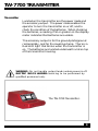
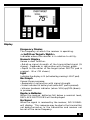
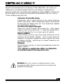
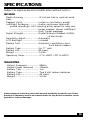
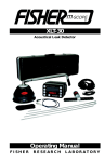
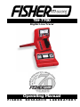
TW-7700
Digital Line Tracer
Operating Manual
FISHER
RESEARCH
LABORATORY
CONTENTS
Description.............................................................................. pg. 3
Transmitter ............................................................................. pg. 4
Receiver ................................................................................... pg. 5
Accessories .............................................................................. pg. 7
Operating Instructions ......................................................... pg. 8
Depth Accuracy ...................................................................... pg. 9
Specifications ......................................................................... pg. 10
DESCRIPTION
The TW-7700 Digital Line Tracer consists of a transmitter, receiver,
ground-plate/ground-rod assembly, carrying case (hard or soft),
and an operators manual. The TW-7700 is a single frequency line tracer.
The TW-7700 is an active locating line tracer. There
are three methods of active locating that an operator
can use to trace a utility. The conductive method is
the most preferred method, since a strong transmitter
signal is transmitted through the intended target. The
inductive method is the easiest method to use, but
may not yield the best results. When a direct connection is not available, but the operator has good knowledge of where one point of the utility may be, the operator can place the Transmitter over the utility making sure that the arrow on top of the transmitter is
parallel to the path of the utility. The third method of
active locating involves using the coupling clamp accessory. The coupling clamp is used when the utility is
exposed, but a direct connection is not available. The
clamp jaws are opened and placed around the utility.
The clamp never makes a direct connection with the
utility, that is, the utility can move freely with the
clamp around it.
The features of the TW-7700 make it a very easy and
practical instrument in today’s world of underground
locating.
1
3
TW-7700 TRANSMITTER
Transmitter
Located on the transmitter are the power mode and
the accessory output. The power mode enables the
operator to turn the transmitter on or off, and to
check the condition of the batteries. When checking
the batteries, a reading if 50 or greater on the display
meter indicates that batteries are usable.
The accessory output is for the ground plate/ground
rod assembly, and for the coupling clamp. There is a
Red LED light that blinks when the transmitter is
on. The batteries are located underneath a lid on top
of the transmitter housing.
WARNING: Do not handle output leads unless power is off.
ELECTRIC SHOCK HAZARD: Servicing to be performed by
qualified personnel only.
The TW-7700 Transmitter.
4
TW-7700 RECEIVER
Receiver
The TW-7700 Receiver.
Controls
Mode
This button does not have a function on the TW-7700.
(It allows users of the TW-8800 Multi-Frequency Line
Tracer to change frequencies.)
Power On/Off
Turns the receiver on or off.
Light
Lights up the display for usage in dark areas. When the
display is backlit, LIGHT is shown on the bottom left hand
side of the display screen.
Bat
Press and hold this pad to check the battery level of the
receiver. A bar graph on the right side of the display will
give status of the batteries. When the graph shows 1 bar,
it is time to replace the batteries. Additionally, as the
operator uses the Receiver, if the batteries get low, REPLACE BATTERIES will appear in the lower area of the
Display screen.
Vol(up)/Vol(down)
Increases or decreases the volume of the speaker.
Depth
After determining the centerline of the utility, set the
blade of the receiver on the ground, press and hold this
pad to get the depth to the center of the target.
5
TW-7700 RECEIVER
Display
Frequency Modes
The frequency at which the receiver is operating.
<< Left/Over Target>/Right>>
Indicates where the receiver is in relation to utility.
Numeric Display
Serves a dual function:
•Relative signal strength of the transmitted signal (%
shown). Responds in conjunction with the bar graph.
•Depth to the center of the target (when DEPTH pad is
pressed - IN or CM shown)
Light
Indicates the display is lit (activated by pressing LIGHT pad).
Bar Graph
Serves three purposes:
•Responds in conjunction with signal strength.
•Visual indicator for battery test (when BAT pad is pressed).
•Volume loudness indicator (when VOL(up)/VOL(down)
is pressed.
Replace Batteries
When the receiver batteries fall below a nominal level,
REPLACE BATTERIES will be displayed.
No Signal
When no signal is received by the receiver, NO SIGNAL
will display. This response may be due to the transmitter
not being turned on, or the transmitter and receiver not
be set at the same frequency.
6
ACCESSORIES
Coupling Clamp
The coupling clamp is useful when the utility is exposed,
and a direct connection is not possible. It is plugged into
the same plug-in socket as the ground-plate/ground-rod
assembly. The coupling clamp only operates at the 82
kHz frequency. The coupling clamp will fit around utilities that are 3-¼ inches in diameter or smaller. The length
of the cable is approximately 10 feet.
Coupling Clamp Applications Diagram
A. The coupling clamp is for all
tracing applications with conductors exposed; exception, an
open circuit at line’s termination.
B. A ground must be provided for
the proper current flow when the
coupling clamp is used at a termination.
C. The coupling clamp must be
used between the grounding
and where the line goes underground.
D. Trace signal will return to
ground
when
incorrectly
coupled.
E. Signal will be transmitted in
both directions when connecting is midway in a long conductor.
F. Drop lines or laterals divide the
signal strength in half at each
junction.
This represents a jumper
Headsets
Fisher Research Laboratory has a variety of headsets available.
•Ultra-quiet deluxe Fisher Phones. High quality sound
while reducing the outside noise.
•Standard Stereo Headphones
•Single Earpiece Headset. Enables the operator to effectively listen to the TW-7700 and remain aware of noise in
close proximity.
7
OPERATING INSTRUCTIONS
The following instructions are designed for a safe and effective
method of line tracing and utility avoidance. Some of the steps
may not be applicable in all situations. The underlying guideline is
that operator safety must be maintained at all times. Use of
safety equipment, extra personnel, and up to date as-built plans
should be considered when necessary.
INITIAL SCAN
Set-up Transmitter either Inductively or Conductively
Inductive
Be aware of air coupling, the transmitted signal travelling
to the Receiver via the air, not the utility.
Conductive
Connect the ground plate/ground rod assembly to the transmitter. Connect the red lead to the non energized utility. Connect the black lead to the ground plate/ground rod. Place the
plate/rod at a 90 degree angle in reference to the utility. Be
sure not to place the wires over any other utility.
After transmitter set-up, move away from the point of connection (or Induction) about 25 feet (8 meters). Sweep a
circle around the point of connection. Initially, disregard
the LEFT/RIGHT indicator and rely on the signal strength
readout. Make note of the high readings. These are areas
that need to be traced/examined in more detail.
Tracing
After locating the point(s) where the signal strength was
the highest, return to that/those points and start tracing
your utility. This is where the LEFT/RIGHT indicator is
very helpful. Swing the receiver from left to right and listen for the change of tone. When the target is to the RIGHT
of the receiver, the tone is pulsed tone. As the receiver
gets closer to the target, the pitch gets higher. When the
target is to the LEFT of the receiver, the tone is a continuous tone. As the receiver gets close to the target, the pitch
also becomes higher. When the receiver is over the target,
OVER TARGET is displayed on the display screen, and the
tone is at its highest peak sound.
Depth Measuring
When an OVER TARGET response is displayed, position
the blade of the receiver directly over the utility and
place the tip on the ground. Hold the receiver steady,
press and hold the DEPTH pad. Depth will be measured
to the center of the utility.
8
DEPTH ACCURACY
Depth measurement is a feature of the TW-7700. Accuracy is
defined on an ideal target, that is, one that is continuous, a
good conductor, and not surrounding by other utilities. There are
factors that can cause the operator to question the accuracy
of the utility being traced.
Inductive Transmitter Setup
Inductively, only a small portion of the signal attaches
itself to the utility. With a weakened signal, trace should
be accurate, but depth may not. The conductive method
will yield better results.
Low Receiver Signal Strength
When the signal strength falls below 20 – 25%, depth
readout may not be accurate. It would be beneficial to
move the transmitter to a closer point of contact.
Nearby Utilities
Close, nearby utilities may have some influence on the
accuracy of the Depth readout. This is more prone to
happen in the higher frequencies where signals can jump
to nearby utilities. Switching to a lower frequency can
give better results.
Moisture
Ground that is too dry or overly saturated may skew the
depth readout.
“T’s”, elbows, or splits in the utility can distort the
transmitted signal in that general area.
WARNING: Do not connect output leads to a live
(energized) utility. Please prevent shock hazard and
equipment damage.
9
SPECIFICATIONS
Subject to improvement or modification without notice.
RECEIVER
Depth Accuracy ...................... +1 inch per foot in nominal conditions
Readout Units ........................ Inches or cm (factory preset)
Left/Right Guidance ............... Audio: continuous tone=Left,
pulsed tone=Right. VCO (varying pitch) output for easy over
........................................... target location. Visual: Left/Right/
........................................... Over Target messages
Signal Strength ...................... Digital Numeric Readout (0-99%)
& Bar Graph
Sensitivity Adjust ................... Automatic
LCD Backlight ........................ Included
Battery Test ........................... Automatic Low Battery alert
Push button readout
Battery Type ........................... Six “C” cells
Battery Life ............................ 80 Hours
Weight ..................................... 5.4 lbs.
Operating Temp ..................... -4 0 to +1400F (-200 to +600C)
TRANSMITTER
Output Frequency .................. 82kHz,
Output Power (nominal) ........ .5Watts,
Battery Test ........................... Yes
Battery Type ........................... Two 6 Volt lantern batteries
Battery Life ............................ 80 Hours
Weight ..................................... 5.0 lbs.
Fisher Research Laboratory does not warrant suitability to specific use. Fisher
Research Laboratory shall in no event be liable for any direct, incidental, consequential or indirect damages.
10
NOTES
QUALITY
Fisher detectors are renowned for their quality.
Each detector is hand crafted in the USA with pride
PERFORMANCE
Our detectors and locators are durable, dependable, and
search deeper.
REPUTATION
Fisher produced the first patented metal detector in 1931. For
over 70 years, the Fisher logo has been a mark of excellence.
2 YEAR WARRANTY
Fisher believes in the products we produce and backs this belief
with a 2 year limited warranty. Warranty may vary outside the
United States. See your dealer for details
SERVICE
Fisher is committed to providing you, our valued customer, with
superior service. Each and every instrument is rigidly tested and
carefully inspected during assembly and before shipment. Should
you have any questions or problems, contact:
FISHER RESEARCH LABORATORY
200 W. Willmott Rd.,
Los Banos, CA 93635
Tel 209.826.3292 Fax 209.826.0416
www.fisherlab.com email:[email protected]
EXPORT DEPARTMENT
FRL 8708002-A
P.O. Box 1896
New Haven, CT 06508 USA
Tel 203.288.1638 Fax 203.287.8099
email:[email protected]