1
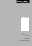
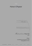
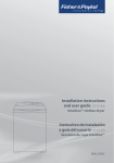
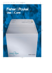
Electric Dryer
DEGX1US
Installation instructions
Important safety instructions
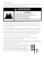
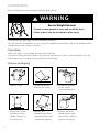
WARNING
To reduce the risk of fire, electric shock, or injury to persons when using your appliance, follow
basic precautions, including the following:
1. Read all instructions before using the appliance.
2. Installation and service must be performed by a qualified installer or service agency.
3. Make sure the power cord is located so that it will not be stepped on, tripped over or
otherwise subject to stress or damage.
4. Pressing the POWER button to turn the dryer off, does NOT disconnect the dryer from the
power supply, even though the dryer lights are out.
5. Do not operate this dryer if it is damaged, malfunctioning, partially disassembled or has
missing or broken parts, including a damaged cord or plug.
6. Do not dry articles that have been previously cleaned in, washed in, soaked in, or spotted
with, gasoline, dry-cleaning solvents, other flammable or explosive substances as they give off
vapors that could ignite or explode.
7. Close supervision is necessary if this dryer is used by or near children. Do not allow children to
play inside, around or with this dryer or any other appliance.
8. Before the appliance is removed from service or discarded, remove the lid and drum door to
the drying compartment.
9. Do not reach into the appliance if the drum is moving.
10. Do not install or store this appliance where it is exposed to water and or the weather.
11. Do not tamper with the controls or the lid lock.
12. Do not repair or replace any part of the appliance or attempt any servicing unless specifically
recommended in the user-maintenance instructions or in published user-repair instructions
that you understand and have the skills to carry out.
13. Unless specifically recommended by their manufacturer, do not use fabric softeners or similar
products in a tumble dryer.
14. Do not use heat to dry articles containing foam rubber or similar textured rubber-like materials.
15. Check to see if the lint bucket needs emptying. Empty before the lint reaches the top of the
transparent section (usually once a week).
16. Keep area around the exhaust opening and adjacent surrounding areas free from the
accumulation of lint, dust, and dirt.
17. Have the interior of the appliance and exhaust duct cleaned periodically by qualified service
personnel.
18. Do not place items exposed to cooking oils or other vegetable oils in your dryer. Items
contaminated with cooking and other vegetable oils may contribute to a chemical reaction
that could cause a load to catch fire.
SAVE THESE INSTRUCTIONS
2
Read this before you start installing your dryer
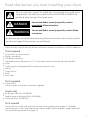
This is the safety alert symbol. This symbol alerts you to hazards that can kill or hurt
you and others. The safety alert symbol and the word DANGER or WARNING will
precede all safety messages. These words mean:
DANGER
You can be killed or seriously injured if you don’t
immediately follow instructions.
WARNING
You can be killed or seriously injured if you don’t follow
instructions.
All safety messages will identify the hazard, tell you how to reduce the chance of injury, and tell
you what can happen if the instructions are not followed.
Check to make sure you have all the tools and parts necessary to correctly install this appliance.
Tools required
1⁄4’’ nut driver or socket wrench
Phillips screwdriver
Flat-blade screwdriver
Adjustable wrench that opens to 1’’ or 1’’ hex-head socket wrench (for adjusting the feet)
Level
Caulking gun and compound (for installing new exhaust vent)
Gloves
Safety glasses
Knife
Duct Tape
Parts supplied
2 feet inserts
Check to make sure all parts have been supplied.
Accessories
Kit Element 208V Part No 395500
Mobile Home Installation Kit Part No 395488
Drying Rack Part No 395332P
Parts needed
Check with local codes and read electrical and venting requirements (pages 8–18) before
purchasing parts. If you need to purchase a power supply cord kit or power supply cable, they
must meet the requirements on page 18.
3
To the installer
The correct installation of the dryer is your responsibility.
Be sure you read the following instructions carefully before you start to install the dryer. These
instructions should be left with the home owner for future reference.
It is your responsibility to:
Observe all governing codes and ordinances.
Check code requirements. Some codes limit or do not permit installation of clothes dryers in
garages, closets, mobile homes or sleeping quarters. Contact your local building inspector.
Adhere to these installation instructions.
Allow for spacing requirements with side by side installations (refer page 6).
Make sure you have all items necessary for correct installation.
Properly install the dryer.
Contact a qualified installer to ensure that the electrical installation meets all national and local
codes and ordinances.
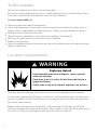
Location requirements
WARNING
Explosion Hazard
Keep flammable materials and vapours, such as gasoline,
away from the dryer.
Place dryer at least 18 inches (46 cm) above the floor for a
garage installation.
Failure to do so can result in death, explosion, fire, or burns.
The dryer must be installed or stored in an area which is not exposed to water or weather.
It is extremely important that the dryer is installed in a well ventilated location. This dryer must
exhaust air outdoors. Do not install the dryer in any room or closet which does not permit the
free flow of replacement air.
Before installing the dryer ensure that there is sufficient height to fully open the lid. Allow
sufficient room behind the dryer for the exhaust. The air intake is at the rear of the dryer. Ensure
that there is a sufficient air passage on each side of the dryer for intake air.
4
The area in which the dryer is located must be kept clear and free from combustible materials,
gasoline and other flammable vapours and liquids. A dryer produces combustible lint so the area
around the dryer must be cleaned regularly to keep it free of lint.
This dryer can only be vented from the rear and must be exhausted to the outdoors.
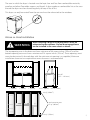
Alcove or closet installation
WARNING
When installing a dryer in a closet/alcove it must be
exhausted to the outdoors. No fuel burning appliance
can be installed in the same closet or alcove.
The top opening area in the door must be a minimum of 48 square inches (310cm2) and the
bottom opening area must have a minimum of 24 square inches (155cm2). These openings must
never be obstructed (a louvred door with the minimum air opening is acceptable). Minimum
installation clearances are required but more clearance is recommended.
min 56"
(1372 – 1422mm)
1" (25mm)
1" (25mm)
1" (25mm)
min 2" (50mm) min 3" (76mm)
48 sq" (310cm2)
total ventation area
72 sq" (465cm2)
24 sq" (155cm2)
5
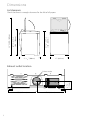
Dimensions
Lid clearance
�� ���� � �� �����
���� � ������
�� ���� � �� �����
����� � �������
��� ����� � �������
Check that there is enough clearance for the lid to fully open.
�� ����� �������
��� �������
Exhaust outlet location
4 3/ 8"
(111mm)
Exhaust outlet
13 7/8" (352mm)
6
13 1/8" (333mm)
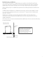
Mobile home installation
The installation of the dryer in a mobile home must conform to the Manufactured Home
Construction and Safety Standard Title 24 CFR, Part 32-80 {formerly the Federal Standard for
Mobile Home Construction and Safety, Title 24 HUD (Part 280), 1975} for the United States.
When installing a dryer in a mobile home, provisions for anchoring the dryer to the floor must
be made.
A Mobile Home Installation kit is available with instructions (see Accessories page 3). Locate
in an area that has adequate make up air (a minimum of 72 square inches of unobstructed
opening is required).
Mobile home installations must be exhausted to the outdoors with the exhaust duct
termination securely fastened to the mobile home structure, using materials that will not
support combustion.
The exhaust duct must not terminate beneath the mobile home. See the section on exhausting
for more information.
��� ����� ���� ��
��������� �������
�������
����
��� ������� ���� ���� �� ��������
�������� �� � ���������������
������� �� ��� ������ ����
��������� ��� ���� ��� ���������
������� ��� ������ �����
�����
�������� ����
��������
7
Exhausting
The dryer must be exhausted to the outdoors. This will prevent the build up of lint and moisture
in the room in which it is located and reduce the risk of fire.
WARNING
Fire Hazard
The dryer must be vented to the outdoors.
Use rigid or thick wall flexible metal exhaust duct.
Do not use a plastic exhaust duct.
Do not use a metal foil exhaust duct.
Failure to follow these instructions can result in death or fire.
This appliance must always be vented to the outdoors.
Exhaust ducting products can be purchased from your local Appliance store or Hardware store.
Plastic or metal foil flexible duct can kink, sag, be punctured, reduce airflow, extend drying times
and affect dryer operation.
A minimum of 4 inch (100mm) thick wall flexible metal or rigid galvanised metal duct must be
used. Using ducts larger than 4 inches (100mm) diameter may result in more lint accumulating.
Using straight rigid metal ducting will minimise lint accumulation. Thick wall flexible metal
ducting may be used but care must be exercised to avoid sharp bends which may squash the
duct & cause blockages. Do not use plastic ducting or thin wall flexible metal ducting.
Use duct tape to secure joints. Do not use screws as they collect lint.
Keep ducting as short and straight as possible. Do not exceed the maximum exhaust duct
lengths stated later in these installation instructions.
Do not exhaust the dryer into a chimney or gas vent, a wall, a ceiling or any concealed space in a
building. Do not exhaust the dryer under a house or mobile home or a porch, or into a window
well or other area that will accumulate lint.
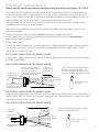
The exhaust duct should end with an exhaust hood with a swing
out damper to prevent back drafts and entry of wild life. Never use
exhaust hoods with a magnetic damper. The hood should have
at least 12 inches (305mm) clearance between the bottom of the
hood and the ground or other obstruction. The hood opening
should point down. Never install a screen over the exhaust outlet.
8
12" (305mm)
To reduce condensation, insulate any ducting which passes through unheated areas.
Slope the duct gently downwards to the hood, to drain condensation and reduce lint build up.
Avoid sag or loops in the duct as they may collect and store water and accumulate lint.
Before using an existing exhaust duct system for a dryer ensure that:
No plastic or other potentially combustible duct or flexible metal foil ducting has been used.
The duct is not pierced, kinked or crushed.
The duct does not exceed the maximum recommended length for the new dryer.
The exhaust hood damper opens and closes freely and with sufficient movement.
Static pressure in the exhaust ducting does not exceed 1 inch (250Pa), or is not less than 0 inches
of water column (ie. negative pressure), when measured with a manometer in the first 6 inches
of the duct, with the dryer running on Air Dry (no heat) setting.
The exhaust duct system meets all relevant local, state and national codes.
All ducting should be inspected and cleaned at least once a year to remove accumulated lint.
Frequently check that the damper on the exhaust hood moves sufficiently and opens and
shuts freely.
Mobile home installations
A Mobile Home Installation Kit is available (see Accessories page 3 and notes page 7).
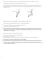
Determine vent duct length
This dryer can only be vented from the rear and must be exhausted to the outdoors.
Different types of vent arrangements are shown below.
9
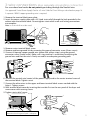
Choose a route that will provide the straightest and most direct path outdoors. Plan the
installation to use the fewest number of elbows and turns.
When using elbows (rigid duct) or making turns (thick wall flexible metal duct), allow as much
room as possible. With thick wall flexible metal duct bend duct gradually to avoid kinking and
avoid 90˚ turns.
recommended
acceptable
Maximum length of exhaust duct
The maximum length of the exhaust duct system depends upon:
The type of ducts (rigid or thick walled flexible metal).
The number of elbows or bends used.
1. Refer to the exhaust duct length chart that matches your hood type for the maximum duct
lengths you can use. Do not use duct runs longer than specified in the exhaust duct length
charts (refer to next page).
Exhaust duct systems longer than specified will:
Accumulate lint creating a potential fire hazard.
Shorten the life of the dryer.
Reduce performance, resulting in longer drying times and an increased energy usage.
2. Determine the number of elbows/bends you will need.
3. In the column listing the type of metal duct you are using (rigid or thick wall flexible metal),
find the maximum length of metal duct on the same line as the number of elbows/bends to
be used (refer to next page).
10
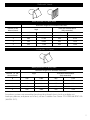
Preferred 4” Hoods
When you have a 4” (10cm) Hood
Maximum length of 4” diameter metal duct.
Number of 90˚
elbows/bends
Thick Wall Flexible Metal
(fully extended)
Rigid
0
64ft
19.5m
36ft
10.9m
1
54ft
16.5m
31ft
9.4m
2
44ft
13.4m
27ft
8.2m
3
35ft
10.6m
25ft
7.6m
4
27ft
8.2m
23ft
7.0m
Acceptable 2 1⁄2”Hood
When you have a 2 1⁄2” (6cm) Hood
Maximum length of 4” diameter metal duct.
Number of 90˚
elbows/bends
Rigid
Thick Wall Flexible Metal
(fully extended)
0
58ft
17.6m
28ft
8.5m
1
48ft
14.6m
23ft
7.0m
2
38ft
11.5m
19ft
5.7m
3
29ft
8.8m
17ft
5.1m
4
21ft
6.4m
15ft
4.5m
For exhaust systems not covered by the exhaust duct length charts (such as multiple unit
hook-ups, plenums, and power-assist fans), call our Customer Care Center: TOLL FREE 888 9FNP USA
(888 936 7872).
11
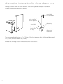
Alternative installation for close clearances
Venting systems come in many varieties. Select the type best for your installation.
A close-clearance installation is shown.
swivel collar
wall connection
sections separate,
fittings can face
same or opposite
swivel collar
Extra long
band–clamp
for dryer
connection
telescoping
sections
beveled edges
allow corner
installations
The maximum length using a 2” x 6” (5cm x 15cm) rectangular duct with two elbows and a
2 1⁄2”(6.3cm) exhaust hood is 8ft (2.4m).
Refer to the venting system kit manufacturers instructions.
12
Exhaust venting
WARNING
Fire Hazard
Use heavy metal exhaust duct.
Do not use a plastic exhaust duct.
Do not use thin metal foil exhaust duct.
Failure to do so can result in death or fire.
1. Read the exhaust section (page 8–12) before installing the exhaust system to determine the
maximum allowable exhaust duct length.
Do not use sheet metal screws when assembling ducting. Always use suitable duct tape.
Never use plastic or thin metal foil flexible exhaust material.
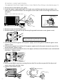
2. The exhaust outlet is located close to the center of the rear of the dryer. Make sure you
join the exhaust duct to the dryer with duct tape only. This will prevent lint and dust from
escaping from the dryer and exhaust system.
4 3/ 8"
(111mm)
Exhaust outlet
13 7/8" (352mm)
13 1/8" (333mm)
3. The exhaust vent can be routed up, down, left, right or straight out the back of the dryer.
Refer to diagram.
13
Installation
Parts and literature are packaged inside the dryer drum.
WARNING
Excess Weight Hazard
Use two or more people to move and install the dryer.
Failure to do so can result in back or other injury.
Only remove the packaging at the customer’s premises.
This will ensure the appliance arrives in pristine condition and reduces the risk of damage when
transporting to the customer’s home.
Unpacking
Make sure dryer is in a suitable location for installation.
Consider installing the dryer before the washing machine in a side by side installation, this will
allow better access to electrical and exhaust connections.
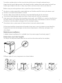
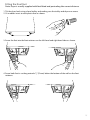
Remove packaging
1.
1. Remove straps.
4.
2.
3.
2. Unfold the bottom
flaps on the carton.
3. Unfold the top flaps
on the carton,
remove top packer.
6.
5.
Tilt
Walk
off
Slide out
4. Remove the carton
by lifting it off the
product (do not cut
the carton off ).
14
5. Remove the
basepacker by tilting
the product back and
walking the product.
6. Remove the drum
packer and the tape
from the lint collector
bucket in the drum.
Fitting the front feet
Note: Dryer is usually supplied with feet fitted and protruding the correct distance.
1. Tilt the dryer back using a hand trolley and making sure the trolley and dryer are secure.
2. Fit a rubber insert to each plastic foot as shown.
3. Screw the feet into the foot retainers on the left hand and right hand sides as shown.
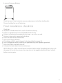
4. Screw both feet in so they protrude ¹⁄₂” (12mm) below the bottom of the wall on the foot
retainers.
15
Electrical requirements
WARNING
Electric Shock Hazard
Use a new UL approved 30-ampere power cord or direct wire
cable.
Use a UL approved strain relief.
Disconnect power before making electrical connections.
Connect neutral wire (white or center wire) to center terminal.
On all four wire installations remove the grounding link and
connect the ground wire to the green ground connecting screw.
Connect remaining 2 supply wires to remaining 2 terminals.
Securely tighten all electrical connections.
Failure to do so can result in death, fire, or electrical shock.
NOTE: The wiring diagram is located in the control console.
The dryer must be plugged into or connected to an individual branch circuit, do not use an
extension cord.
The power supply must be 220/240V or 208V, 60 Hz approved alternating current electrical
service. The electrical service requirements can be found on the data label that is located on the
splash back. A 30-ampere fuse or circuit breaker is required on each of the lines.
If a power cord is used, the cord must be plugged into a 30-ampere receptacle.
The power cord is NOT provided with U.S. electric model dryers.
This dryer is supplied with the cabinet grounded through the neutral on the terminal block.
If the dryer is to be installed in a mobile home or an area where local codes do not permit
grounding through neutral, the appliance grounding link must be removed and a 4-wire power
cord/cable or a separate grounding wire must be used.
Do not reuse a power supply cord/cable from an old dryer. The power cord/cable electric supply
wiring must be retained at the dryer cabinet with a suitable UL listed strain relief.
208V Requirements
If your power supply is 208V 60 Hz, a new element kit must be fitted by a qualified electrician or
service representative (see Accessories page 3 for kit part number).
16
WARNING
Electrical Shock Hazard
Make sure appliance is wired or plugged into a grounded
outlet.
Do not use an adaptor.
Do not use an extension cord.
Failure to follow these instructions can result in death, fire,
or electrical shock.
Grounding instructions
WARNING
Electrical Shock Hazard
Check with a qualified electrician or serviceperson if you are
in doubt as to whether the appliance is properly grounded.
Do not modify the plug if it will not fit the outlet.
Have the proper outlet installed by a qualified electrician.
Failure to follow these instructions can result in death, fire, or
electrical shock.
Grounding for a cord-connected appliance
This appliance must be grounded. In the event of malfunction or breakdown, grounding will
reduce the risk of electric shock by providing a path of least resistance for electric current. This
appliance is equipped with a cord having an equipment-grounding conductor and a grounding
plug. The plug must be plugged into an appropriate outlet that is properly installed and
grounded in accordance with all local codes and ordinances.
WARNING
Improper connection of the equipment-grounding
conductor can result in a risk of electric shock. Check with
a qualified electrician or service representative if you are in
doubt as to whether the appliance is properly grounded.
Grounding for a permanently connected appliance
This appliance must be connected to a grounded metal permanent wiring system, or an
equipment grounding conductor must be run with the circuit conductors and connected to the
equipment-grounding terminal on the appliance.
17
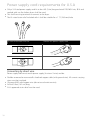
Power supply cord requirements for U.S.A
Only a UL listed power-supply cord kit at least 6ft (1.8m) long and rated 120/240 V min, 30 A and
marked with use for clothes dryers shall be used.
This shall have ring terminals to connect to the dryer.
The UL-rated strain relief included with it shall be suitable for a 1 1/8” (28.5mm) hole.
If your outlet looks like this
Choose this power supply cord
� ����
4 wire
Connecting by direct wire
Power supply cable must match power supply (4-wire or 3-wire) and be:
18
Flexible armoured or non-metallic sheathed copper cable (with ground wire). All current-carrying
wires must be insulated.
10 gauge AWG solid copper wire (do not use aluminium wire).
At least 6 feet (182 cm) long.
A UL approved strain relief must be used.
Electrical connections
Please read Electrical requirements and grounding instructions on pages 16–18 first.
The DEGX1 electric model of the SmartLoad™ dryer is manufactured for a 3-wire connection
system. The dryer frame is grounded by a link to the neutral conductor on the dryer terminal
block. If local codes do not permit grounding through the neutral, the grounding link from the
terminal block must be removed and a separate ground wire must be used.
The grounding link on the dryer must be removed for all 4-wire installations including new,
remodelled construction, or mobile homes.
These Electrical Connection instructions provide for installing the SmartLoad™ dryer in the
following situations:
3-wire connection where local codes permit grounding through the neutral.
3-wire connection plus separate grounding connector where local codes do not permit
grounding through the neutral.
4-wire connection.
Each of the above connections can be made with an approved power supply cord or by direct
wiring. Each connection instruction identifies the appropriate Power Supply Cord & covers
requirements for direct wiring.
For 3-wire connections by power cords
3-wire power supply cord must have three 10 AWG copper wires and match a 3-wire receptacle
of NMEA Type10-30R.
For 3-wire connections by direct wiring
3/ ” UL-listed
4
strain relief
to disconnect
box
Three-wire with ground
wire: Bare wire cut short.
Wire not used. Dryer is
grounded through neutral
or separate grounding
10-gauge, 3-wire or,
10-gauge, 3-wire with
ground wire (Romex)
Strip 41/4” of outer covering from end
of cable. Strip insulation back 1”. If
using 3-wire cable with ground wire,
cut bare wire even with outer covering.
1” of wires
stripped of
insulation
NEUTRAL wire
(white or center)
Shape ends of wire
into a hook.
4 1/ 4
For 4-wire connections by power cords
4-wire power supply cord must have four 10 AWG copper wires and match a 4-wire receptacle of
NMEA Type14-30R. The fourth wire (ground conductor) must be identified by a green cover and
the neutral wire by a white cover.
For 4-wire connections by direct wiring
4 1/ 4”
3/
4” UL-listed
strain relief
1” of wires
stripped of
insulation
to disconnect
box
10-gauge, 3-wire with ground
bare ground wire
wire (Romex)
NEUTRAL wire
(white or center)
Strip 41/4” of outer covering from end of
cable. Strip insulation back 1”.
Shape ends of wire
into a hook.
19
3-wire connections
For use where local codes permit grounding through the Neutral wire.
Use approved 3-wire Power Supply Cord or a 3-wire Cable for Direct Wiring as described on page 18.
1. Remove the terminal block cover plate.
2. Insert the power cord with a UL listed strain relief through the hole provided in the cabinet near
the terminal block. Do not tighten strain relief screw until wiring connections are complete.
Note: a strain relief must be used.
2
strain relief
clamp sections
strain relief
screws
3. Loosen or remove the center terminal block screw. Connect the neutral wire (center) of the
power supply cord to the center terminal screw of the terminal block. Tighten screw.
4. Connect the other wires to the upper and lower terminal block screws marked with the
letter L. Tighten screws.
4
3
Note: If the appliance is
moved back to a 3-wire
installation the ground
link must be refitted.
4
5. Refit terminal block cover by inserting the two tabs first on the rear panel of the dryer. Secure
cover with securing screw.
6. Tighten strain relief screws.
5
20
6
3-wire connections plus separate grounding connector
For use where local codes do not permit grounding through the Neutral wire.
Use approved 3-wire Power Supply Cord or a 3-wire Cable for Direct Wiring as described on page 18.
A separate 10AWG copper grounding wire is required.
1. Remove the terminal block cover plate.
2. Insert the power supply cable with a UL listed strain relief through the hole provided in the
cabinet near the terminal block. Do not tighten strain relief screw until wiring connections
are complete.
Note: a strain relief must be used.
2
strain relief
clamp sections
strain relief
screws
3. Remove center terminal block screw.
4. Remove appliance ground link by removing the ground connector screw (Green screw).
5. Connect a separate copper ground wire (green with yellow stripe) using the ground
connector screw (Green screw). Make sure a ring terminal is used when connecting the
ground wire and that the wire is firmly secured to an adequate grounding path.
3
7
6
4
5
7
6. Connect the neutral wire (center) of the power supply cord to the center terminal screw of
the terminal block. Tighten screw.
7. Connect the other wires to the upper and lower terminal block screws marked with the
letter L. Tighten screws.
8. Refit terminal block cover by inserting the two tabs first on the rear panel of the dryer and
secure cover with securing screw.
9. Tighten strain relief screws.
8
9
grounding wire
It is recommended that a qualified electrician
determine that the ground path is adequate
21
4-wire connections
Use approved 4-wire Power Supply Cord or a 4-wire Cable for Direct Wiring as described on page 18.
1. Remove the terminal block cover plate.
2. Insert the power supply cable with a UL listed strain relief through the hole provided in the
cabinet near the terminal block. Do not tighten strain relief screw until wiring connections are
complete.
Note: a strain relief must be used.
2
strain relief
clamp sections
strain relief
screws
3. Remove center terminal block screw.
4. Remove appliance ground link by removing the ground connector screw (green screw).
3
4
Note: If the appliance is moved back to a 3-wire
installation the ground link must be refitted.
5. Connect ground wire (green) of the power supply cord to the ground conductor green screw.
Tighten screw.
6. Connect the neutral wire (white) of the power supply cord to the center terminal screw of the
terminal block. Tighten screw.
7. Connect the red wire and black wire to the upper and lower terminal block screws marked with
the letter L. Tighten screws.
7
6
5
7
8. Refit terminal block cover by inserting the two tabs first on the rear panel of the dryer and
secure cover with securing screw.
9. Tighten Strain Relief screws.
8
22
9
Level machine
Check the dryer is level, and make necessary adjustments to the front levelling feet.
The rear levelling feet are self adjusting.
Final installation check list
Check that:
No plastic or flexible metal foil is used in the exhaust ducting.
Exhaust is rigid ducting or thick wall flexible metal ducting.
All joints in the ducting are made with duct tape – no screws are used.
Ducting is clean and is connected to the dryer.
Inserts are fitted to the two front feet.
Dryer is level across the front.
If installation is 208 V, special element kit has been fitted (see page 16).
Dryer is plugged or directly wired into an approved fitting and is properly grounded.
Dryer starts, heats, cools and shuts off.
Customer has been shown how to use the dryer.
NB: This dryer has a drum reversal feature to reduce clothes tangle. Throughout the drying cycle
the motor will run for four minutes, then stop & run in the opposite direction for forty seconds
before reversing again.
23
Copyright Reserved © Fisher & Paykel 2004.
The product specifications in this booklet apply to
the specific products and models described at the
date of issue. Under our policy of continuous product
improvement, these specifications may change at any
time. You should therefore check with your Customer
Care Center to ensure this booklet correctly describes
the product currently available.
www.fisherpaykel.com
US
Installation Instructions
Published: 03/2004
Part No. 395217A