1
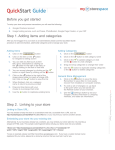
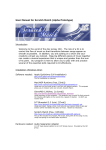
PS1010-3A
Multifunctional
Digital DC power supply
USER MANUAL
•
•
•
•
•
Voltage controllability
Current controllability
Digital voltmeter function
High power efficiency
Bright display
IBBI Electronics
1
Table of Contents
1
2
3
4
5
Safety precautions...................................................3
Device overview .....................................................3
Getting started.........................................................3
Operating conditions...............................................4
Device operation .....................................................5
5.1
Setting output voltage .....................................5
5.2
Setting current limit ........................................5
5.3
Viewing actual current flow............................5
5.4
Voltmeter mode ..............................................6
5.4.1
Measuring voltage at various positions
while powered from the PS1010-3A.......................6
5.4.2
Measuring voltages at external sources ..7
5.5
Viewing firmware version ..............................7
6
Troubleshooting ......................................................8
7
General information ................................................9
IBBI Electronics
2
1 Safety precautions
•
•
•
Do not operate under Lightning conditions
Do not keep in wet areas
Always adjust required voltage/current, before
connecting the power lines to the DUT
2 Device overview
PS1010 is a PWM controlled highly power efficient
digital power supply. The features extend to;
• Voltage controllability
• Current controllability
• Measuring voltage at any point in the
device/circuit under test while powered from the
PS1010-3A
• Measuring voltage at any out side source such as
a battery or any other voltage point
• Display capability of any of the followings
o Out put voltage
o Actual current flow
o SET Current limit
o Voltage as a voltmeter
o Firmware version/Error codes
3 Getting started
IBBI Electronics
3
1
2
3
4
5
6
11
10
9
8
7
1. Power switch
2. Display-value
3. Display-unit/information
4. LED panel
5. Output voltage controller
6. Current limit controller
7. C-limit display selection
8. Voltage-Current display selection
9. Voltage out put terminal
10. Voltmeter-V/C display selection
11. Voltmeter + terminal
4 Operating conditions
Unit
Input voltage
230V AC
Input frequency
50Hz
Out put voltage
0-30V
Out put current
0-3A
IBBI Electronics
4
Voltmeter range
0-35V
5 Device operation
5.1 Setting output voltage
•
•
•
•
•
Put VM/Vout switch [(10)] to Vout position
Put C/V switch [(8)] to V position
Volt LED indicator will light up [(4)]
[(3)] will display “U” for Volt
Adjust the voltage controller [(5)] to get the
required value.
• The value will be displayed on [(2)] with one
decimal place
Note: Make sure to keep reasonable current limiting
value before setting output voltage so that current
control (CC) will not take over.
5.2 Setting current limit
•
•
Press and hold C-SET button [(7)].
Then display[(2)] will show the present current
limit in Amperes.
• [(3)] will display “A” for Current
• Now rotate the current controller knob [(6)]
while looking at the display. Stop when the
desired value appears.
Note: The output voltage will be automatically be
controlled if the external device tries to drag current
more than the set limit.
5.3 Viewing actual current flow
•
Power up the DUT with PS1010-3A
IBBI Electronics
5
•
•
•
•
•
Put VM/Vout switch [(10)] to Vout position
Put C/V switch [(8)] to C position
Amp LED indicator will light up [(4)]
[(3)] will display “A” for Ampere
Actual current value will be displayed on [(2)]
with two decimal places
5.4 Voltmeter mode
5.4.1 Measuring voltage at various
positions while powered from the
PS1010-3A
•
Set required output voltage and power up the
DUT
• Put VM/Vout switch [(10)] to VM position. VM
LED indicator [(4)] will light up.
• Test voltage values using the VM probe [(11)].
The voltage values are displayed relative to the
GND pin of the Vout terminal [(9)].
Note: the user can select various switch positions at
any time to see the Current limit, Actual current
flow, voltage at output terminals or at VM without
disrupting the power at the output terminals.
IBBI Electronics
6
5.4.2 Measuring voltages at external
sources
•
•
•
Put VM/Vout switch [(10)] to VM position. VM
LED indicator [(4)] will light up
Connect wires as shown below(VM terminal and
the GND of Vout terminals)
Value will be displayed [(2)].
5.5 Viewing firmware version
•
•
•
Switch OFF the PS1010 [(1)]
Put VM/Vout switch [(10)] to VM position
Press and hold the C-SET button
IBBI Electronics
7
•
•
•
Switch ON the PS1010-3A [(1)]
[(3)] will show “F” to indicate Firmware version
Display [(2)] will show the Firmware version in
the following order.
6. 0. 1
Major version
F
Build
Minor version
Note: PS1010-3A is not firmware upgradeable by
the customer.
6 Troubleshooting
No display
• Check power cable/Input power
• Check power switch [(1)]
• Check fuse at the back of the PS1010
Even if the voltage adjust knob is turned the value
does not vary.
• Check whether the Volt LED indicator [(4)] is
ON. If not then you are not in the right set up
and follow up on how to setting the output
voltage guide lines
• Check whether the CC LED indicator [(4)] is
ON. If so then the current limiting occurs due to
insufficient current limit adjustment or due to
excessive current draw.
IBBI Electronics
8
PS1010 is in its current mode and the Amp indicator
is also ON. But rotating current controller knob does
not affect the display value.
• You are at the current mode and at this mode the
display shows only the actual current draw by
the DUT. But rotating the current controller knob
means changing the Max current limit. To see
the max current limit, C-SET button should be
pressed.
Cannot increase voltage from a certain value.
• Check whether CC indicator appears. If so,
increase the current limit.
7 General information
Terminology
DUT- Device Under Test
Warranty terms and conditions:
Warranty will apply only for the circuit but not for any
other. Warranty will void if case was previously open or
attempted to repair. Under any physical damages,
damages caused by lightning or due to miss-use
conditions, the warranty will not be applicable. The
customer must fill the Warranty activation card and post
it to IBBI Electronics to receive within 14 days of
purchase or mail a scanned copy.
Customers are not encouraged to do any repair from out
side even if the warranty expires.
IBBI Electronics
9
Contact details:
IBBI Electronics,
No185/B, Opatha,
Kotugoda.
Sri Lanka.
Email: [email protected]
Tel/Fax: +94 11 229 6812
Web: http://ibbi.electronics.googlepages.com/
IBBI Electronics
10