1
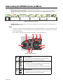
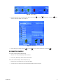
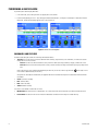
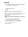
Quick Start
DVR OPERATION
Using Your DVR
This Quick Start guide provides guidelines on the basic operation of the
DVR5100. Refer to the DVR5100 Series Hybrid Video Recorder Operation
manual (C1696M) for complete instructions on operating your unit.
DVR5100 Series
Hybrid Video Recorder
TURNING ON THE DVR5100
Press the power button located on the right front side of the DVR5100. The Pelco logo turns blue when power is applied.
During startup, the DVR5100 reads configuration files from the flash card, and then copies them to a protected partition on the hard disk drives.
This mirroring of the operating system drive is a critical aspect of the reliability designed into the DVR5100. Once turned on, the two databases
are synchronized regularly. If a hard disk drive failure occurs, this synchronization ensures that the system can recover quickly and efficiently by
replacing the failed drive. The startup time is extended as a result of the database synchronization.
The DVR5100 front panel control pad contains four color-lit function buttons (refer to Figure 1).
Figure 1. Control Pad Color-Coded Function Buttons
The lights of the control pad cycle through various color combinations during the startup process. Once complete, the blue and red function
buttons are steady. At this point, you can either log on to the unit or change the output monitor configuration.
Changing the Monitor Configuration
The default DVR5100 monitor configuration is VGA. You should see the login prompt if you are using a VGA monitor. To use a composite or
S-Video monitor, change the output mode as follows:
•
Press Menu
•
Press the yellow function button
.
for NTSC or the green function button
for PAL.
The unit will restart in a composite monitor output mode.
Figure 2 shows the monitor selection label that is positioned on the top rear of the DVR5100.
Figure 2. Monitor Selection Label
LOGGING ON
NOTE: The first time you start the DVR5100, the system automatically starts a 60-second counter. This feature allows the system to
automatically log on a designated user each time the DVR is restarted (for example, after a power failure or when the unit is restarted for any
reason). You can enable or disable the autologin feature, select a different default user to log on, and change the default countdown timer from
the General System setup menu. The admin user ID is the default setting (refer to Figure 3).
Figure 3. Autologin Dialog Box
3
C2657M-A (7/08)
LOGGING ON WITH A KEYBOARD AND MOUSE
To log on using a keyboard and mouse:
1. Select the user from the User ID list.
2. Click in the Password box, and then type the password.
3. Click Log In to accept the user name and password. If the password is correct, the DVR5100 displays the main application window.
The default user IDs and passwords are as follows:
•
admin: admin or 23646
•
manager: manager or 6262437
•
operator: operator or 67372867
•
guest: guest or 48378
LOGGING ON WITH THE CONTROL PAD
Table A lists the control pad functions at login.
Table A. Special Logon Controls
Control Pad
Functions
Jog (inner dial)
Cycles through the list of users (by default, the options are admin, guest, manager, and operator).
Blue function button
Press to display the on-screen password keypad. (Refer to the keypad instructions in this table.)
Green function button
Press to log on to the DVR5100 once the password is entered.
Red function button
Press to shut down the DVR5100 once the password is entered.
When the on-screen password keypad is open…
Joystick
Navigates up, down, left, and right through the keypad’s number grid.
Enter/Shift button
Enters the currently selected number into the password box.
Green function button
Saves the entered password and closes the keypad.
Red function button
Clears the entered password and closes the keypad.
To log on using the control pad:
1. Turn the Jog (inner dial)
C2657M-A (7/08)
to select the user name. The default user IDs and passwords are as follows:
•
admin: admin or 23646
•
manager: manager or 6262437
•
operator: operator or 67372867
•
guest: guest or 48378
4
2. Press the blue function button
. The on-screen keyboard appears (refer to Figure 4).
Figure 4. Login Dialog Box
3. Use the Joystick
to navigate to the first number of your password, and then press Enter/Shift
.
4. Repeat step 3 until you have entered the entire password.
5. Press the green function button
to the Login dialog box.
to accept the password, or press the red function button
to cancel the password and return
6. From the Login dialog box, select Log In to accept the user name and password.
5
C2657M-A (7/08)
Understanding the DVR5100 Controls and Menus
The DVR5100 is menu-driven, and you can operate the unit using any of the following options:
•
USB PC keyboard, mouse, and template: Use the included USB PC keyboard and mouse to configure and operate the DVR5100. This is
the easiest way to operate the unit. A template is included to provide a quick reference for all available keyboard shortcuts (refer to
Figure 5).
Figure 5. USB PC Keyboard Template
•
DVR5100 control pad: If it is not convenient to use the USB PC keyboard and mouse for your installation, use the front panel controls to
configure and operate the DVR5100.
NOTES:
•
Directions for configuring and operating the DVR5100 are given for the USB PC keyboard and mouse, and for the DVR5100 control pad.
Throughout this document, the first part of the instructions refer to keyboard and mouse operation, followed by instructions in brackets
([ ]) for control pad operation.
•
Refer to Table B through Table E on pages 7 through 10 for descriptions of the control pad functions.
Figure 6. DVR5100 Control Pad
Blue Function Button:
• Active when on-screen menus are displayed (selects blue menu items).
•
“Quick Export” when on-screen menus are not displayed.
Yellow Function Button:
• Active when on-screen menus are displayed (selects yellow menu items).
•
“Go to live” when on-screen menus are not displayed.
•
Press and hold for Quick Search when on-screen menus are not displayed.
Green Function Button:
• Active when on-screen menus are displayed (selects green menu items).
•
C2657M-A (7/08)
“Play/pause” when on-screen menus are not displayed.
6
Red Function Button:
• Active when on-screen menus are displayed (selects red menu items).
•
“Change layout” when on-screen menus are not displayed.
•
Press and hold for full-screen when menus are not displayed.
Jog (inner dial)
Shuttle (outer ring)
Menu
Plus (+)/Minus (–) buttons
Enter/Shift
Joystick
•
DVR5100 remote client: For advanced programming and remote access, use the DVR5100 remote client application. Refer to the
DVR5100 Remote Client Operation manual (C1697M) for more information.
USB PC KEYBOARD/MOUSE AND CONTROL PAD FUNCTIONS
Table B describes the USB PC keyboard/mouse and DVR5100 front panel controls that are available when you view live or recorded video, when
on-screen menus are not visible. Live video is indicated by a green border; recorded video is indicated by a yellow border; and pan/tilt/zoom (PTZ)
mode is indicated by a blue border.
Table B. Live and Playback Controls (1 of 2)
Keyboard
Control Pad
Right, Left, Up, and
Down Arrows
Function
Joystick
F5–F8
Change layout
Navigates to a different video pane.
Keyboard: Press F5 (single), F6 (2 x 2), F7 (3 x 3), and F8 (4 x 4) to
change the screen layout.
Control pad:
• Press “Change layout” to toggle the screen layout from
single, 2 x 2, 3 x 3, and 4 x 4 display layouts.
•
Plus (+)/Minus (-)
Plus (+)/Minus (-) buttons
Press Plus to display the next camera in the sequence in the
currently selected video pane.
Press Minus to display the previous camera in the sequence.
Numeric keypad + F9
Menu +
Blue function + Blue function
Keyboard: Type the desired camera number, and then press F9 to
jump directly to that camera.
Control pad: Opens the Camera Selection dialog so you can
choose a specific camera without cycling through the sequence.
0 (zero) + F9
< or , (comma)
> or . (period)
7
Press and hold “Change layout” to jump straight to
single/full-screen video for the currently selected camera.
N/A
Type 0 (zero), and then press F9 to disconnect a camera.
Jog (inner dial)
Keyboard: Press < or , (comma) to step backward. Press > or .
(period) to step forward.
Control pad: Turn the jog counterclockwise to step backward or
clockwise to step forward.
C2657M-A (7/08)
Table B. Live and Playback Controls (2 of 2)
Keyboard
Control Pad
Function
Shuttle (outer ring)
Keyboard: Press < or , (comma) for fast rewind. Press > or .
(period) for fast-forward.
Control pad: Turn the shuttle counterclockwise for fast rewind,
clockwise for fast-forward. To increase speed, turn the shuttle
farther in the desired direction.
Shift + < or , (comma)
Shift + > or . (period)
Enter/Shift
Play/pause
Shuttle (outer ring)
Keyboard: Press the Shift key while repeatedly pressing < or ,
(comma). Press > or . (period) to rewind or fast-forward to lock in
the current speed (2x, 4x, 15x, 60x, or 300x). Press P to cancel the
speed setting.
Control pad: Press Enter/Shift while using the shuttle to rewind
or fast-forward to lock in the current speed (2x, 4x, 15x, 60x, or
300x). Press “Play/pause” or turn the shuttle to cancel the speed
setting.
L
Go to live
Press L or “Go to live” to switch from viewing recorded video to
viewing live video from the currently selected camera.
S
Quick Search
Keyboard: Press S to open the Quick Search dialog box.
Control pad: Press and hold “Quick Search” for 3 seconds to
open the Quick Search dialog box.
P
Play/pause
Press P or “Play/pause” to toggle between play back and pause.
You can press this button while viewing live video.
Ctrl + Left arrow,
Ctrl + Right arrow
Enter/Shift +
Jog (inner dial)
Keyboard: Press Ctrl plus the left or right arrow to turn the
volume up or down.
Control pad: Press and hold Enter/Shift while turning the jog
(inner dial) to adjust the volume.
< or , (comma)
> or . (period)
R
Print Scrn
C2657M-A (7/08)
N/A
Starts or stops recording in the currently selected video pane.
Menu + Green function +
Green function
Captures a snapshot (still video image) and saves it to a USB
memory device.
8
Table C describes the keyboard and front panel controls that are available when controlling PTZ on a selected camera when on-screen menus are
not visible. Press Enter/Shift to enter PTZ mode, which is indicated by a blue border around the currently selected video pane. You cannot change
cameras or navigate to a different video pane in this mode.
NOTE: You must be in live mode to activate PTZ. You cannot activate PTZ while in video playback mode.
Table C. PTZ Controls
Keyboard
Control Pad
Function
Z or Enter
Enter/Shift
Press and release to enter or exit PTZ mode.
Plus (+) and Minus (-)
Plus (+)/Minus (-) buttons
Press Plus to zoom in.
Press Minus to zoom out.
Right, Left, Up, Down
Arrows
Left mouse button
and mouse wheel
Joystick
Controls the PTZ camera pan (right/left) and tilt (up/down).
Use the mouse wheel to zoom in and zoom out.
Z or Enter
Enter/Shift
While in PTZ mode, press Z or Enter [or Enter/Shift] to switch the
selected camera back to live view mode.
Table D describes the keyboard and front panel controls available when a menu or dialog is on the screen (Menu mode).
Table D. Menu Controls (1 of 2)
Keyboard
9
Control Pad
Function
M
Menu button
Shows or hides on-screen menus.
Esc (Escape)
Red function button
Closes the current dialog box.
Tab, Right/Left arrow
Joystick
Moves to the next item in a menu or field in a dialog box
Enter
Enter/Shift
Selects currently highlighted menu item
F1
Blue function button
Selects the blue item on the current menu or dialog.
F2
Yellow function button
Selects the yellow item on the current menu or dialog.
F3
Green function button
Selects the green item on the current menu or dialog.
F4
Red function button
Selects the red item on the current menu or dialog.
Up/down arrow,
Page up/down
Jog (inner dial)
Scrolls through different options in a list or drop-down menu.
Backspace
Shuttle (outer ring)
Backs up one menu level. If a text field is selected, this function
moves the cursor through the characters in the field.
C2657M-A (7/08)
Table D. Menu Controls (2 of 2)
Keyboard
Control Pad
Plus (+) and Minus (-)
Alphanumeric
keypad
Function
Plus (+)/Minus (-)
In a number field, Plus (+) increases the value and Minus (-)
decreases the value.
Blue function button +
Jog (inner dial) [for Keypad
only]
Use any alphanumeric key on the keyboard to enter information in a
text box such as a password, IP address, comment, and so on. Do
not enter characters that are not valid for the currently selected
item; refer to the specific instructions for guidelines on valid
entries. Refer to the descriptions in this table for additional
functions for specific characters.
Table E describes the keyboard and front panel controls available when using the Quick Search dialog.
Table E. Quick Search and Export Controls
Keyboard
Control Pad
Function
S
Quick Search
Keyboard: Press S to open the Quick Search dialog box.
Control Pad: Press and hold “Quick Search” for 3 seconds to open
the Quick Search dialog box.
NOTE: You can also open Quick Search by navigating through the
menus: Menu + green function + blue function.
Right or Left Arrows,
Page Up, Page Down
Jog (inner dial)
Moves the time line slider to the right or the left.
Plus (+)/Minus (-) buttons
Plus (+) and Minus (-)
Jog (inner dial)
Shuttle (outer ring)
Keyboard/Control Pad: Press Plus or Minus to zoom in or zoom
out on the Quick Search time line. Zoom levels are year, month,
week, day, hour, minute, and second.
Control Pad: Rotate the jog (inner dial) to move the time line
cursor to the right or left. Rotate the shuttle (outer ring) to zoom in
or zoom out on the time line.
M
Menu button
Press the “M” key [or Menu] in the Quick Search dialog box to
view more Quick Search options.
X
Quick export
Displays or hides the Quick Export menu. Options include Export
Video, Mark, and Snapshot.
DISPLAYING AND HIDING SYSTEM MENUS
Once logged on, press the “M” key [or Menu
menu hierarchy.
] to display and hide the on-screen menus. Refer to Figure 8 on page 12 to view the Main
Figure 7. DVR5100 Main Menu
C2657M-A (7/08)
10
NAVIGATING TO AND SELECTING A MENU ITEM
USB PC KEYBOARD AND MOUSE
To select a menu item using the USB PC keyboard and mouse:
1. Click the item with your mouse, or use the right or left arrow key, and then press Enter. The yellow cursor denotes the selected menu item.
2. You can also select one of the four colored-coded icons by pressing F1 (blue), F2 (yellow), F3 (green), or F4 (red).
3. Click Back to return to a previous menu.
CONTROL PAD
Joystick
1. Use the joystick to move left or right to a menu item. The yellow cursor denotes the highlighted menu item.
2. Press Enter/Shift
to select the highlighted menu item. To return to a previous menu, tap the joystick
to the Back icon, and
then press Enter/Shift.
Function Buttons
The DVR5100 control pad contains four color-coded function buttons. The color of each button corresponds to the on-screen menu items
displayed in the DVR5100 main application window.
To navigate through the different levels in menus or to select an item:
1. Press the color-coded function button that corresponds to the on-screen menu item.
2. To return to a previous menu, turn the Shuttle (outer ring)
displays a dialog box.
clockwise. After you make a selection, the DVR5100 presents a menu or
Jog/Shuttle
There are two ways to return to a previous or higher level menu:
11
•
Turn the Jog (inner dial)
•
Turn the Shuttle (outer ring)
to the right or left to select the Back icon, and then press Enter/Shift
.
counterclockwise.
C2657M-A (7/08)
ON-SCREEN MENUS
The DVR5100 on-screen menu hierarchy presents only those menus for which you have permission. Depending on your user role, you might see
all available menus or only a few. The default user roles are Administrator, Manager, Operator, and Guest. The menu descriptions in this section
are based on the Administrator role, which has access to all menus and functions. Figure 8 shows the DVR5100 Main menu hierarchy.
NOTE: Contact your system administrator if you need authorization to access additional menus.
Figure 8. DVR5100 Main Menu Hierarchy
MONITORING LIVE VIDEO
The DVR5100 starts in live video mode. The following information describes how to work in this mode.
NOTE: Video panes display the cameras and layouts selected from the last login.
SELECTING A VIDEO PANE
When you start the unit and display a layout with several video panes, the upper left video pane is selected by default. To select a different video
pane, click in another video pane with the mouse, or use the keyboard arrow keys [or the Joystick
] to move left, right, up, and down. The
border of the currently selected video pane changes color to reflect the current operating state of the DVR5100.
•
Green: Indicates the camera is in live view mode (currently selected video screen).
•
Yellow: Indicates the camera is in playback mode.
•
Blue: Indicates that PTZ mode is enabled in the video pane.
•
Red: Indicates that manual recording is in progress in the video pane.
CHANGING THE SCREEN LAYOUT
The screen layout can be changed by pressing the F5–F8 keys. [Or, each time the Change Layout function button
screen layouts is displayed.]
is pressed, one of four
•
Full-screen view (1 x 1): Press F5 [or “Change layout”] to display a single video pane. You can also double-click the left mouse
button in the live view mode pane for a full-screen configuration. [Press and hold “Change Layout” for a full-screen mode.]
•
Four-camera view (2 x 2): Press F6 [or “Change layout”] to display 4 video panes in rows of two.
•
Nine-camera view (3 x 3): Press F7 [or “Change layout”] to display 9 video panes in rows of three.
•
Sixteen-camera view (4 x 4): Press F8 [or “Change layout”] to display 16 video panes in rows of four.
C2657M-A (7/08)
12
VIEWING A SPECIFIC CAMERA
When you select a camera, its video stream is sent to the currently selected video pane. For example, if your display is set to a 2 x 2 layout and
the upper left video pane is selected, you can choose any camera to display in that video pane. Follow the instructions below to move through the
camera sequence, call up cameras by number, and disconnect cameras.
Figure 9. 2 x 2 Video Pane Configuration
MOVING THROUGH THE CAMERA SEQUENCE
Although a camera is displayed in a specific video pane, you can quickly cycle through the list of cameras in the sequence.
To sequence through the list of cameras:
1. Select the video pane displaying the desired camera.
2. Press Plus (+) on the keyboard’s numeric keypad [or
previous camera in the video pane sequence.
] to view the next camera in the sequence. Press Minus (-) [or
] to view the
CALLING UP CAMERAS BY NUMBER
To call up a camera by a logical number (keyboard only):
1. Select the video pane to display the desired camera.
2. Type a camera number (the camera must be enabled).
3. Press F9. The camera is displayed in the selected video pane.
CALLING UP CAMERAS THROUGH THE CAMERAS MENU
To select a camera through the Cameras menu:
1. Select a video pane to display the desired camera.
2. Press the “M” key [or Menu
] for the Main menu.
3. Click Cameras [or use the Jog (inner dial)
menu appears (refer to Figure 10).
13
or Joystick
to select Cameras, and then press Enter/Shift
]. The Cameras
C2657M-A (7/08)
Figure 10. Cameras Menu
4. Click Select Camera [or move to Select Camera using the Jog (inner dial)
or Joystick
, and then press Enter/Shift
]. The
Camera List dialog box appears (refer to Figure 11).
Figure 11. Camera List
5. Click a camera [or use the Jog (inner dial)
or Joystick
to select a camera, and then press Enter/Shift
].
DISCONNECTING CAMERAS
To disconnect a camera by number (keyboard only):
1. Navigate to the video pane displaying the desired camera.
2. Press 0 (zero), and then press F9. The camera is disconnected.
To disconnect a camera through a shortcut menu (mouse only):
1. Right-click in the selected video pane. A shortcut menu appears.
2. Select Disconnect. The camera is disconnected and video disappears from the video pane.
C2657M-A (7/08)
14
PERFORMING A QUICK SEARCH
To perform a quick search and play back video:
1. In live view mode, select a video pane that is displaying video from a camera.
2. From the USB keyboard, press the "S" key to bring up the QuickSearch dialog box, or navigate to Search/Export > QuickSearch from the
Main menu. The QuickSearch dialog appears (refer to refer to Figure 12).
Figure 12. Quick Search Dialog Box
COMMANDS AND FEATURES
The Quick Search dialog box contains the following commands and features:
•
Time line: Units of time increase or decrease between months and days, days and hours, hours and minutes, or minutes and seconds.
Change the units of time as follows:
–
Zoom in: Roll the mouse wheel towards the screen [or turn the Shuttle (outer ring) clockwise] to display a smaller unit of time.
–
Zoom out: Roll the mouse wheel away from the screen [or turn the Shuttle (outer ring) counterclockwise] to display a larger unit of
time.
Click in the time line to move forward or backward along the time line. [You can also turn the Jog (inner dial)
move forward or backward along the time line.]
to the right or left to
Along with stars that indicate a marked event, the graphical indicator for recorded video represents recorded video with four different
colored bars:
•
Green: Continuous recording
•
Red: Alarm recording
•
Blue: Motion recording
•
Yellow: Manual recording
You can also locate marked or locked video as follows:
15
•
Marked Video: The video time line is marked with a star so that certain video can be located easily in a Quick or Enhanced Search.
•
Locked Video: The video time line shows a white line and brackets that reflect the time range for a locked video clip.
C2657M-A (7/08)
PRIMARY FUNCTIONS
•
Export: Opens the Export dialog box.
•
Lock/Unlock Toggle: Locks select video from being deleted. Locked video left on the storage drives reduces the system storage capacity.
Unlocking removes the lock and allows video to be overwritten as part of the normal overwrite process. This toggle changes to Unlock if
you move your time line cursor above a locked clip.
–
If the video clip is large, the cursor may change to a clock during the locking process.
–
A white line and brackets reflect the time range for the locked video clip.
To lock a clip:
•
Move the slider with the mouse [or Jog (inner dial)] to the beginning of the desired period, and then press Lock.
•
Move the slider to the end time, and then press Lock again.
To unlock a locked clip:
•
Position the slider on the locked clip (white line across the recording bar).
•
Select Unlock
NOTE: As you set the start and end times, the values are displayed in the information bar at the bottom of the screen.
•
Play: Starts to play back the video from the slider position along the time line. The camera, time, and date are displayed above the time
line. The dialog box remains open.
•
Close: Closes the Quick Search dialog box. Video continues to play if you previously pressed Play. Otherwise, the video pane remains in
the same state as when the Quick Search dialog box was opened.
•
More: Displays the secondary functions in the Quick Search dialog box (Enhanced Search, Mark, and Snapshot).
SECONDARY FUNCTIONS:
•
Enhanced: Closes the Quick Search dialog box and opens the Enhanced Search dialog box (refer to Performing an Enhanced Search on
page 17).
•
Mark:
–
Places a mark on the video so that it can be located easily in a Quick or Enhanced Search.
–
Updates the Quick Search graph to show the mark (star).
–
Flashes a message on the information bar to confirm that the marking process is successful.
To mark video, select the time and camera, and then press Mark. A star appears indicating the marked video.
•
Snapshot:
–
Stores the snapshot (a still image) on an attached USB device using your default snapshot format.
–
Flashes a message on the information bar to confirm the capture.
•
More: Returns you to the primary Quick Search dialog box.
•
Close: Closes the Quick Search dialog box.
•
Export: Select Export to export the video to an external storage device.
C2657M-A (7/08)
16
PERFORMING AN ENHANCED SEARCH
To perform an enhanced search:
1. In the live view mode, press the “E” key or navigate to Enhanced Search through the Main menu and Search/Export. The Enhanced Search
dialog box opens (refer to Figure 13).
Figure 13. Enhanced Search Dialog Box
2. Click the Time Range box [or navigate to the Time Range box, and then turn the Jog (inner dial)
right or left] to select the time range
(“Last 24 hours,” “Last 3 days,” “Last 7 days,” and “Specific time range”).
3. If you select “Specific time range,” you must select a time and date range for the search as follows:
•
Keyboard and mouse: Click in the Start and End time and date fields, and then type the specific time range. Or, click the up and down
arrow to select the specific time range.
•
Control pad:
–
Use the Joystick
to navigate between time and date boxes. The first field (hours) is selected by default.
–
Turn the Jog (inner dial)
–
Turn the Shuttle (outer ring)
to change the values.
to move to the next field after each change is made.
4. Select a camera or cameras from the Cameras list (“All Cameras,” “Multiple cameras,” or individual cameras). If you select “Multiple
cameras,” press Enter [or Enter/Shift
], or select the button
next to the Cameras box. The Select Cameras dialog box
appears (refer to Figure 14).
NOTE: By default, all cameras are selected. You must clear the selection for cameras that you do not want to search.
17
C2657M-A (7/08)
a.
Click the desired cameras [or turn the Jog (inner dial)
to select a camera, and then press Enter/Shift
].
Figure 14. Select Cameras Dialog Box
b.
Click OK when your list is complete [or use the Joystick
to navigate to OK, and then press Enter/Shift
].
5. Select a video type or types from the Types field (All Types, Multiple Types, Continuous, Motion, Alarms, Manual, Marked, and Locked).
If you select Multiple Types, press Enter [or Enter/Shift
], or select the ellipsis button
beside the Types box. The Select
Search Type dialog box appears (refer to Figure 15).
NOTE: By default, all types are selected, as indicated by the gray area of the dialog box.
a.
Click the desired recording types for your search [or turn the Jog (inner dial)
Enter/Shift
]. Repeat this step to select more than one recording type.
to select a recording type, and then press
Figure 15. Search Dialog Box
b.
Click OK when your list is complete [or select OK, and then press Enter/Shift
].
6. Click Search [or press Menu
] to start the search. The Enhanced Search dialog box displays a list of results along with details about
each recording (camera name, start and end times, and recording type).
7. Select a recording result [or turn the Jog (inner dial)
to select a recording], and then perform any of the following actions:
•
Export: Select Export to export the video to an external storage device (refer to Exporting Video on page 19).
•
Lock: Select Lock to lock the video so it cannot be overwritten.
•
Play: Select Play to view the video (refer to Playing a Video Clip on page 19).
•
Close: Select Close to close the Enhanced Search dialog box.
NOTE: You can sort your results by clicking any of the column headings in the Enhanced Search dialog box.
C2657M-A (7/08)
18
PLAYING A VIDEO CLIP
You can play back recorded video by starting play from either QuickSearch or Enhanced Search. Select the time and camera or specific clip and
press Play. You can also take advantage of Instant Playback by rewinding the jog shuttle or pressing the “P” key from a live display.
Changing the Playback Speed for Recorded Video
While playing back recorded video, you can play the video at several speeds in either a fast-forward or fast-reverse direction.
To change the playback speed for recorded video:
1. Select a video pane that is playing back recorded video (yellow border).
2. Press < or > to step backwards or forwards one frame at a time. Press the Shift key while repeatedly pressing < or , (comma) to rewind.
Press > or . (period) to fast-forward to lock in the current speed (2x, 4x, 15x, 60x, or 300x). Press the “P” key to cancel the speed setting.
[Or, turn the Shuttle (outer dial)
clockwise to play the video in fast-forward, or turn the Shuttle
counterclockwise to play the
video in fast-reverse.] The farther you turn the shuttle, the faster the video plays forward or backward. Release the shuttle to return to the
normal forward speed.
3. Press the “L” key [or the “Go to live” function button
] to return to live view mode.
EXPORTING VIDEO
Quick Export and Quick Search may be quickly accessed by selecting Export Video. There are three paths for exporting a video clip:
•
Quick Export menu
•
Quick Search dialog box
•
Enhanced Search dialog box
To export a video clip from the Quick Export menu:
1. Select a video pane that is displaying video to be exported (exporting can start in live or playback mode).
2. Press the “X” key [or the Quick Export button
]. The Quick Export menu appears (refer to Figure 16).
Figure 16. Quick Export Screen
19
C2657M-A (7/08)
3. Select Export Video. The Export Clip dialog box appears (refer to Figure 17).
NOTE: The following are the default start and end times:
•
Arriving from Live: The previous 10 minutes.
•
Arriving from Quick Search: The currently selected time on the time line plus 10 minutes forward.
•
Arriving from Enhanced Search: The whole video clip, defined by the video clip’s start and end times.
Figure 17. Export Clip Dialog Box
4. Select your destination (CD/DVD or USB device).
5. Select the output format (Pelco Video File with Player, Pelco Video File without Player, or QuickTime® MPEG-4).
NOTE: When exporting in the MPEG-4 format, the system will not export associated audio, the time and date stamp, or the digital
signature required to authenticate a clip.
6. To select the export video time frames, do one of the following:
•
Click and drag the gray bar in the time line [or turn the Jog (inner dial)
] to adjust the end time. The vertical blue bar represents
the start time and is fixed. If you drag the gray bar to the left of the blue bar, the gray bar becomes your start time indicator and the
blue bar indicates the end time. You can drag the time line to the right or the left of the time line cursor.
•
Type [or select] the desired start time, end time, and dates in the Start and End time/date fields.
NOTE: Selecting Set Time resets the time line at its fixed point. This allows you to reset the desired video time frame for export. Select the
time line, and then drag to the left or right to select the video clip.
7. Select Begin Export. The video export begins is a USB storage device is present.
NOTE: If a USB storage device is not available, a dialog box will appear asking you to insert the specified device.
C2657M-A (7/08)
20
CAPTURING A SNAPSHOT (STILL IMAGE)
All snapshots are saved in a default folder called “images,” which is created automatically on a USB device. You must attach a USB device to the
DVR5100 before you start to capture a snapshot. If a USB device is not attached, an error message appears and the snapshot is not saved.
To capture a snapshot:
1. Attach a USB device to the unit in one of the USB ports.
2. Select a video pane that is displaying video from which you want to capture a snapshot, and then do one of the following:
•
Press the Print Scrn key.
•
Press the “X” key [or the Quick Export function button
•
Press the “S” key [or the Quick Search function button
] to display the Quick Export menu (refer to Figure 18).
for 3 seconds] to display the Quick Search menu.
Figure 18. Selecting Snapshot from the Quick Export Menu
3. Select Snapshot. A snapshot is saved to the USB memory key and a message appears in the information bar confirming the save. Repeat
this step for each still image.
4. Select Close to close the Quick Export screen.
SHUTTING DOWN THE DVR5100
WARNING: Do not shut down the DVR5100 by turning off the power. Doing so can cause data loss or may corrupt the database. Always
follow the procedures in this section to turn off the unit.
Use the following steps to shut down the DVR5100. For security purposes, the DVR5100 can be shut down only if you have Administrator level
permissions.
1. From the Login screen, select the admin user ID, and then enter the appropriate password.
2. Select Shut Down to power off the system. The DVR5100 saves all configuration information and recorded video, and then shuts down.
3. If you are already logged on, use the on-screen menus to log off, and then follow the steps above.
LOGGING OFF
You can log off from the system without shutting down the unit. This allows the DVR5100 to continue recording while preventing unauthorized
access to the unit.
NOTE: Autologin must be disabled to log off from the system without shutting down the unit. With autologin disabled, the Login dialog box
remains on the screen and you or another operator can log back on to the system. While you are logged off, the system continues to record as
configured.
To log off, select Logout
, and then press Enter/Shift
.
SUMMARY
The information presented in this document represents only a small subset of the features that are available with the DVR5100. Consult the
DVR5100 Series Hybrid Video Recorder Operation manual (C1696M) for complete instructions on operating your unit. Refer to the resource CD
that is included in the unit for electronic versions of the entire documentation set for both the DVR5100 server and remote client applications.
21
C2657M-A (7/08)
C2657M-A (7/08)
22
REVISION HISTORY
Manual #
C2657M
C2657M-A
Date
10/06
7/08
Comments
Original version.
Added new and enhanced features for easier configuration; added keyboard and mouse operating instructions; made textual changes throughout the document.
Pelco, the Pelco logo, Endura, and the Endura logo are registered trademarks of Pelco, Inc.
EnduraStor is a trademark of Pelco, Inc.
QuickTime is a registered trademark of Apple Inc.
©Copyright 2008, Pelco, Inc. All rights reserved.
The materials used in the manufacture of this document and its components are compliant to the requirements of Directive 2002/95/EC.
Worldwide Headquarters
3500 Pelco Way
Clovis, California 93612 USA
USA & Canada
Tel: (800) 289-9100
Fax: (800) 289-9150
International
Tel: +1 (559) 292-1981
Fax: +1 (559) 348-1120
www.pelco.com
ISO9001
Australia
| Finland | France | Germany | Italy | Macau | The Netherlands | Russia | Singapore
| Spain | Sweden | United Arab Emirates | United Kingdom | United States
South Africa