1
Bulletin 71.1:Y690A
HORIZONTAL PIPELINE
VENT POINTED DOWN
VENT POINTED DOWN
HORIZONTAL PIPELINE
DOWNSTREAM CONTROL LINE
TYPE Y690AH
TYPE Y690AHM
B2626
INLET PRESSURE
OUTLET PRESSURE
ATMOSPHERIC PRESSURE
DOWNSTREAM CONTROL PRESSURE
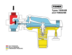
Figure 3. Types Y690AH and Y690AHM Actuator Casing Drainage Schematic
Table 5. Outlet Pressures and Spring Part Numbers
Outlet Control
Pressure Ranges
Spring PART
NUMBER
Spring
COLOR
1 to 2.5-inches w.c. / 2 to 6 mbar
2.5 to 7-inches w.c. / 6 to 17 mbar
5 to 10-inches w.c. / 12 to 25 mbar
7 to 16-inches w.c. / 17 to 40 mbar
15-inches w.c. to 1.2 psig / 37 to 83 mbar
1.2 to 2.5 psig / 83 to 172 mbar
2.5 to 4.5 psig / 0.17 to 0.31 bar
4.5 to 7 psig / 0.31 to 0.48 bar
1B558527052(1)(2)
1B653827052(1)
1B653827052
1B653927022
1B537027052
1B537127022
1B537227022
1B537327052
Orange
Red
Red
Unpainted
Yellow
Light green
Light blue
Black
TYPEs
Y690A and Y690AM
Y690AH and Y690AHM
Spring Wire
Diameter
Inches
mm
0.072
1.8
0.085
2.2
0.085
2.2
0.105
2.7
0.114
2.9
0.156
4.0
0.187
4.8
0.218
5.5
Spring free
length
Inches
mm
3.78
96.0
3.63
92.2
3.63
92.2
3.75
95.2
4.31
109
4.06
103
3.94
100
3.98
101
1. To achieve the published outlet pressure range the spring case must be installed pointing down.
2. Do not use Fluorocarbon (FKM) diaphragm with this spring at diaphragm temperatures lower than 60°F / 16°C.
Installation
Y690A Series regulators may be installed in any orientation
as long as flow through the body matches the direction of
the arrow cast on the body. Normal installation is with the
spring case barrel vertical above or below the diaphragm
case. However, when using a Type Y690A or Y690AM
regulator, for proper operation to achieve the published
capacities, the spring case barrel should be installed pointed
down. For actuator casing drainage of the Types Y690AH
and Y690AHM, regulators should be installed as shown in
Figure 3. When exposed to the weather, the spring case
vent should be pointed downward to allow condensate to
drain. On indoor installations, the vent should be piped
outdoors if used in hazardous gas service. External
dimensions and connections are shown in Figure 4.
14.7 psia) of 0.6 specific gravity natural gas. For gases
of other specific gravities, divide the given capacity by
the square root of the appropriate specific gravity of the
gas required. Then, if capacity is desired in normal cubic
meters per hour at 0°C and 1.01325 bar, multiply scfh by
0.0268. To determine wide-open flow capacities for relief
sizing, use the following formula:
Q=
4
P
Deg
P1
where,
Capacity Information
Tables 6 and 7 give the regulating capacities of the
Y690A Series regulators at selected inlet pressures and
outlet pressure settings. Flows are in scfh (60°F and
3417
520
CgP1Sin
C1
GT
Cg C1 G
P1abs Q
T
= gas sizing coefficient from Table 2
= Cg / Cv, or 35 from Table 2
= gas specific gravity (air = 1.0)
= inlet pressure, psia (add 14.7 psi to gauge inlet
pressure to obtain absolute inlet pressure)
= flow rate, scfh
= absolute temperature in °Rankine of gas at inlet