1
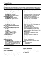
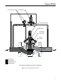
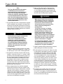
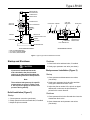
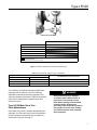
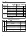
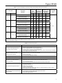
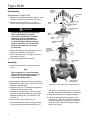
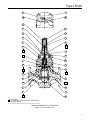
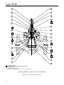
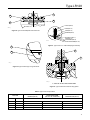
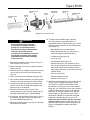
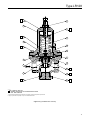
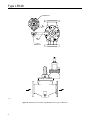
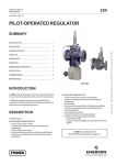
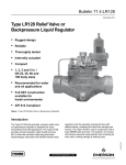
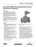
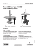
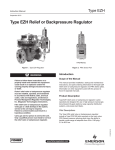
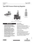
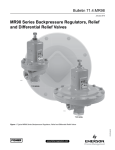
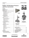
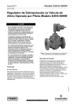
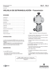
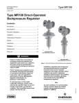
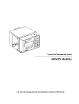
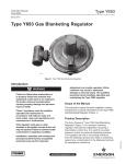
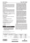
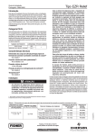
Type LR128
Instruction Manual
November 2014
Type LR128 Relief Valve or
Backpressure Liquid Regulator
TyPE LR128 REguLaTOR
TyPE MR98H PILOT
Figure 1. Type LR128 Relief Valve or Backpressure Regulator and Type MR98H Pilot
may be required. Failure to correct trouble
could result in a hazardous condition.
waRNINg
Failure to follow these instructions or
to properly install and maintain this
equipment could result in bursting
of the equipment and/or chemical
contamination causing property damage
and personal injury or death.
Fisher® relief valves and backpressure
regulators must be installed, operated
and maintained in accordance with
federal, state and local codes, rules
and regulations and Emerson Process
Management Regulator Technologies, Inc.
(Emerson™) instructions.
If the relief valve or backpressure regulator
discharges process fluid or a if leak
develops in the system, service to the unit
Call a qualified service person to service
the unit. Installation, operation and
maintenance procedures performed
by unqualified personnel may result
in improper adjustment and unsafe
operation. Either condition may result
in equipment damage or personal
injury. Only a qualified person must
install or service the relief valve or
backpressure regulator.
The Type LR128 is designed for liquid
service. Do not operate the regulator
in applications where temperatures are
below the process fluid’s freezing point
or above its boiling point which are
dependent on the process fluid and the
application pressures.
www.fisherregulators.com
D103578X012
!
Type LR128
Specifications
Specifications for the Type LR128 relief valve or backpressure regulator are shown below. Other information for the main
valve appears on the nameplate. The control spring range for the pilot is marked on the nameplate of Type MR98H pilot.
Main Valve Body Sizes, End Connection Styles
Type LR128 Main Valve (continued)
and Structural Design Ratings(1)
Spring: 302 Stainless steel or 17-7 Stainless steel
See Table 1
Top Plug: 17-4 Stainless steel
Maximum Inlet Pressures(1)
Bottom Plug: 416 Stainless steel
Type LR128 Main Valve: See Table 1
Inlet Strainer: Stainless steel
Type MR98H Pilot: See Table 2
Diaphragm: Nitrile (NBR) or Fluorocarbon (FKM)
Type 112 Restrictor: 1500 psig / 103 bar
O-Rings: Nitrile (NBR) or Fluorocarbon (FKM)
Maximum Outlet Pressure
Flanged Locknut: 17-4 Stainless steel
Type LR128 Main Valve: See Table 1
Backup Rings: Polytetrafluoroethylene (PTFE)
Type MR98H Pilot: 450 psig / 31.0 bar
Upper Spring Seat: 416 Stainless steel
Relief Set Pressure/Backpressure Control Ranges
Indicator Protector and Cover: Plastic
See Table 3
Indicator Stem: 303 Stainless steel
Main Valve Plug Travel
Indicator Fitting: 416 Stainless steel
1 in. / DN 25: 0.37 in. / 9.4 mm
Travel Indicator Plug: 416 Stainless steel
2 in. / DN 50: 0.68 in. / 17 mm
Type MR98H Pilot
3 in. / DN 80: 0.98 in. / 25 mm
Body: WCC Steel or CF8M Stainless steel
Spring Case: WCC Steel or CF8M Stainless steel
4 in. / DN 100: 1.19 in. / 30 mm
Orifice: 416 Stainless steel
Main Valve Minimum Differential Pressures(1)
Valve Plug: 416 Stainless steel
See Table 6
Guide and Pusher Post: 416 Stainless steel
Main Valve Maximum Differential Pressures(1)
Gasket: Nitrile (NBR) or Fluorocarbon (FKM)
See Table 7
O-rings: Nitrile (NBR) or Fluorocarbon (FKM)
Main Valve Internal Inlet Strainer Sizes
Diaphragm: Neoprene (CR) or Fluorocarbon (FKM)
1 in. / DN 25:
Mounting Parts
12 Mesh (0.0661 in. / 1.68 mm)(2)
Pilot Mounting Pipe Nipple: Plated steel or
2, 3 and 4 in. / DN 50, 80 and 100:
Stainless steel
10 Mesh (0.0787 in. / 2.00 mm)(2)
Pipe Fittings: Plated steel or Stainless steel
Temperature Capabilities(1)
Tubing: Stainless steel
See Table 11
Type 112 Restrictor
Pressure Registration
Body: 15-5 Stainless steel
External: 1/8 NPT
Groove Valve: 416 Stainless steel
Spring Case Vent
Retainer: 416 Stainless steel
Type Y602-12
Construction Materials
Pipe Plug: 316 Stainless steel
Type LR128 Main Valve
O-rings: Nitrile (NBR) or Fluorocarbon (FKM)
Body: WCC Steel, CF8M or CF3M Stainless steel
Options
Bonnet: LF2 Steel or 316/316L Stainless steel
• Pre-piped Pilot Supply
• Travel Indicator
Bonnet Bushing: 416 Hardened Stainless steel
Cage: 15-5 Stainless steel
1. The pressure/temperature limits in this Instruction Manual and any applicable standard or code limitation should not be exceeded.
2. Nominal sieve opening.
Introduction
Product Description
Scope of the Manual
The Type LR128 pilot-operated, relief valve or
backpressure regulator is used for liquid applications
and include a Type 112 restrictor and a 1/2 NPT
Type MR98H pilot.
This Instruction Manual provides installation, startup,
adjustment, maintenance and parts ordering information
for Type LR128 relief valve or backpressure regulator,
1/2 NPT Type MR98H pilot and Type 112 restrictor.
2
Type LR128
TYPE 112 RESTRICTOR
TYPE MR98H PILOT
PM O C
OPTIONAL TRAVEL INDICATOR
MAIN SPRING
DIAPHRAGM AND
PLUG ASSEMBLY
internal
strainer
inlet pressure
outlet pressure
atmospheric pressure
loading pressure
Type LR128 with Type MR98H Pilot and tYPE 112 Restrictor
Figure 2. Type LR128 Operational Schematic
3
Type LR128
Pilot Type Description
Type MR98H – High-pressure relief pilot for 25 to
375 psig / 1.7 to 25.9 bar set pressures. Designed to
handle inlet pressures up to 450 psig / 31.0 bar.
Principle of Operation (Figure 2)
A pressure relief valve is a throttling pressure control
device that limits pressure build-up, it opens to prevent
the rise of internal pressure in excess of a specified
value. Fisher® relief valves cannot be used as ASME
safety relief valves.
pilot valve plug closed. Force from the main spring,
in addition to inlet pressure bleeding through the
Type 112 restrictor, provides downward loading
pressure to keep the main valve diaphragm and plug
assembly tightly shutoff.
When inlet pressure rises above the set pressure,
pressure on the pilot diaphragm overcomes the control
spring to stroke the valve plug open. The pilot then
exhausts loading pressure from the top of the main
valve diaphragm. Inlet pressure unbalance overcomes
the main spring force to open the main valve
diaphragm and plug assembly.
A backpressure regulator is a device that maintains
a desired upstream pressure by varying the flow
in response to changes in upstream pressure. It
functions the same as a relief valve, i.e., it opens on
increasing upstream pressure.
As inlet pressure drops below set pressure, the pilot
control spring overcomes the diaphragm force to
stroke the valve plug down to close. Force from the
main spring, along with pilot loading pressure, pushes
the diaphragm and plug assembly onto the tapered
edge seat, producing tight shutoff.
Relief Valve
Installation
As long as the inlet pressure is below the set pressure,
the Type MR98H pilot control spring keeps the pilot
valve plug closed. Inlet pressure passes through the
Type 112 restrictor and registers as loading pressure
on top of the Type LR128 diaphragm and plug
assembly. Force from the main spring, in addition
to inlet pressure bleeding through the Type 112
restrictor, provides a downward loading pressure to
keep the main valve diaphragm and plug assembly
tightly shutoff.
When the inlet pressure rises above the set pressure,
the pressure on the pilot diaphragm overcomes the
pilot control spring and opens the pilot valve plug. The
pilot then exhausts the loading pressure from the top
of the main valve diaphragm and plug assembly. The
inlet pressure unbalance overcomes the main spring
force and opens the diaphragm and plug assembly.
The pilot continuously exhausts process fluid when the
inlet pressure is above the set pressure.
As the inlet pressure drops below the set pressure,
the pilot control spring closes the pilot valve plug and
the exhaust to atmosphere stops. Force from the main
spring, along with pilot loading pressure, pushes the
diaphragm and plug assembly onto the tapered edge
seat, producing tight shutoff.
Backpressure Regulator
As long as inlet pressure remains below set pressure,
the Type MR98H pilot control spring keeps the
4
!
Warning
Personal injury, equipment damage or
leakage due to escaping process fluid
or bursting of pressure-containing
parts may result if the Type LR128 is
overpressured or is installed where
service conditions could exceed
the limits given in Specifications
section or where conditions exceed
any ratings of the adjacent piping or
piping connections.
To avoid such injury or damage, install a
Type LR128 relief valve or backpressure
regulator where:
• Service conditions are within unit
capabilities (including those in the
Specifications section).
• Service conditions are within applicable
codes, regulations or standards.
Additionally, physical damage to the
relief valve or backpressure regulator
could break the pilot off the main valve,
causing personal injury and property
damage due to escaping process fluid.
To avoid such injury and damage, install
the regulator in a safe location.
Type LR128
Table 1. Type LR128 Main Valve Body Sizes, End Connection Styles, Structural Design Ratings and Maximum Operating Inlet Pressures(1)
MAIN VALVE
BODY SIZE
In.
MAIN VALVE
BODY
MATERIAL
DN
END CONNECTION STYLE(2)
maximum operating
relief (inlet)
pressure including
build-up(3)
psig
bar
Maximum Operating
Outlet Pressure
psig
bar
psig
bar
NPT or SWE (1 and 2 in. only)
1500
103
450
31.0
450
31.0
CL150 RF
290
20.0
290
20.0
290
20.0
CL300 RF
750
51.7
450
31.0
450
31.0
WCC Steel
1, 2,
3 and
4
STRUCTURAL DESIGN
RATING(3)
25, 50,
80 and
100
CL600 RF
1500
103
PN 16/25/40 RF
580
40.0
NPT (1 and 2 in. only)
1440
99.2
450
31.0
450
31.0
CL150 RF
275
19.0
275
19.0
275
19.0
CL300 RF
720
49.6
CL600 RF
1440
99.2
450
31.0
450
31.0
PN 16/25/40 RF
580
40.0
CF8M
Stainless steel
1. The pressure/temperature limits in this Instruction Manual and any applicable standard or code limitation should not be exceeded.
2. Ratings and end connections for other than ASME standard can usually be provided. Contact your local Sales Office for assistance.
3. Maximum cold working pressure (CWP) per ASME B16.34 or product bulletin limit, whichever is lowest. Temperature may decrease these maximum pressures.
Table 2. Type MR98H Pilot Maximum Cold Working Pressure(1)(2)
BODY AND SPRING
CASE MATERIAL
Steel
Stainless steel
BODY SIZE
1/2 NPT
MAXIMUM INLET PRESSURE
MAXIMUM OUTLET PRESSURE
450 psig / 31.0 bar
450 psig / 31.0 bar
1. The pressure/temperature limits in this Instruction Manual and any applicable standard or code limitation should not be exceeded.
2. Temperature and/or the body end connection may decrease these maximum pressures.
Table 3. Relief Set Pressure or Backpressure Control Ranges
PILOT
Type
MR98H
SET PRESSURE RANGE
SPRING WIRE DIAMETER
SPRING FREE LENGTH
psig
bar
In.
mm
In.
mm
25 to 75
70 to 140
130 to 200
150 to 375(1)
1.7 to 5.2
4.8 to 9.7
9.0 to 13.8
10.3 to 25.9(1)
0.234
0.283
0.331
0.394
5.94
7.19
8.41
10.0
2.595
2.44
2.250
5.063
65.9
62.0
57.2
129
SPRING MATERIAL
SPRING PART NUMBER
AND COLOR
Powder-coated steel
Powder-coated steel
Powder-coated steel
Powder-coated steel
ERAA01910A0, Green
ERAA01911A0, Red
ERAA02889A0, Blue
1N943427142, Unpainted
1. 150 to 375 psig / 10.3 to 25.9 bar spring range is for the Type MR98HH pilot construction.
!
Warning
Liquid pressure control systems should
be designed using engineering practices
to eliminate quick control starting or
stopping of the flow stream, which can
produce water hammer.
The robust design of the Type LR128 allows this relief
valve or backpressure regulator to be installed indoors
or outdoors. Type LR128 is designed to withstand the
elements. The powder paint coating protects against
minor impacts, abrasions and corrosion. When installed
outdoors, the Type LR128 does not require protective
housing. However, the Type MR98H pilot should be
oriented so that the pilot spring case vent is pointed
down. Otherwise, make sure the vent is protected
so that rain, moisture, insects or any debris will not
accumulate inside or block the vent assembly.
When installed indoors, no remote venting is required
except on the pilot spring case. Refer to Step 8 of the
following procedure for the correct venting practices.
1. Only personnel qualified through training and
experience should install, operate and maintain
a relief valve or backpressure regulator. Before
installation, make sure that there is no damage
to or debris in the main valve body or pilot. Also,
make sure that all tubing and piping are clean
and unobstructed.
5
Type LR128
Note
The Type LR128 internal inlet strainer
is intended to prevent occasional
large particles from entering the main
valve. If the flowing media contains
continuous particles, upstream filtration
is recommended before the main valve
and in the pilot supply piping (reference
Figure 3). See the Specifications section
for the corresponding mesh size of the
internal inlet strainer.
2. A Type LR128 relief valve or backpressure regulator
may be installed in any orientation, as long as flow
through the unit matches the direction of the arrow
on the main valve body and the pilot vent is pointed
down. However, for easier maintenance, install the
regulator with the bonnet up.
caution
Provide adequate support to the bonnet
when disassembling Type LR128
relief valve or backpressure regulator
installed in a vertical installation or
other application where the bonnet is
not oriented upward. Without adequate
support, the bonnet may fall and cause
physical injury when the cap screws
are loosened.
3. The standard pilot mounting position is as shown
in Figure 1. Rotate the bonnet (key 2, Figure 7) or
the pilot (Figure 14) for other mounting positions.
4. An upstream control line is required and must be
installed – as shown in Figure 3 – into the 1/8 NPT
connection in the pilot body assembly (Figure 14).
Do not make the upstream pipeline connection in
or directly downstream of a turbulent area such
as a swage or elbow. A filter or strainer may be
installed in the control line upstream of the pilot
to provide clean fluid. Inspect and clean this filter
regularly to make sure it is not plugged, which can
prevent proper pilot operation.
5. Run a supply pressure line from the upstream
pipeline to the restrictor inlet (use 3/8 NPT outer
diameter tubing or larger). Install a filter or strainer
upstream of the restrictor, if needed, to keep the
supply source from clogging the restrictor or pilot.
Inspect and clean this filter regularly to make sure
it has not been plugged which can prevent proper
relief valve or backpressure operation.
6
6. Apply a good grade of pipe compound to the
external pipeline threads for a threaded body
or use suitable line gaskets for a flanged body.
Use approved piping procedures when installing
the relief valve or backpressure regulator.
!
Warning
When used in relief valve service, the
Type LR128 may leak toxic chemical to
the environment. In toxic or hazardous
liquid service, leaked chemical may
accumulate and cause personal injury,
death or property damage due to
escaping fluid.
To prevent such injury or damage,
provide piping or tubing to vent the
hazardous liquid to a remote, safe
location away from air intakes or any
hazard-prone location. The exhaust
piping must be designed and installed to
guard against excessive flow restriction.
Protect the vent line or stack opening
against condensation or clogging.
For safety during shutdown, vent valves
are required immediately upstream
and downstream of the main valve on a
backpressure or bypass installation.
7. If system operation during maintenance is required,
install isolating and vent valves as needed.
8 The pilot spring case vent (key 54, Figure 14) must
be kept open to atmospheric pressure. A clogged
pilot spring case vent may cause the relief valve
or backpressure regulator to function improperly.
To prevent plugging (and to keep the spring case
from collecting moisture, corrosive chemicals or
other foreign material) point the vent down, orient
it to the lowest possible point on the spring case
or otherwise protect it. Protect the vent assembly
from icing, moisture or debris that may cause
blockage, as required. Inspect the vent regularly
to make sure it has not been plugged. To change
the vent orientation, twist the vent assembly in the
spring case.
9. To remotely vent a spring case, remove the vent
and install obstruction-free tubing or piping into
the 1/4 NPT vent tapping. Provide protection on a
remote vent by installing a screened vent cap onto
the remote end of the vent pipe.
Type LR128
NON-RESTRICTIVE
VENTS AND PIPING
ALTERNATE PILOT
EXHAUST PIPING
A
TYPE MR98H PILOT
TYPE LR128
MAIN VALVE
TYPE 112 RESTRICTOR
TYPE LR128
MAIN VALVE
BLOCK VALVE STRAINER
BLOCK VALVE
C
D
C
D
CONTROL LINE
STRAINER
A
ALTERNATE CONTROL LINE
STRAINER
BLOCK VALVE
HAND VALVE
TYPE MR98H
ALTERNATE PILOT
EXHAUST PIPING
TYPE 112 RESTRICTOR
MAIN PRESSURE LINE
Backpressure Control
Relief Pressure Control
A - Vent (to downstream piping)
C - To TYPE LR128 Loading chamber
D - Pilot Supply (from upstream)
Figure 3. Typical Type LR128 Installation Schematic
Startup and Shutdown
caution
If pressure is introduced first to the
main valve before the pilot, the main
valve may go wide-open and subject the
downstream system to full inlet pressure.
Note
The maximum inlet pressure for specific
constructions are given in Tables 1 and
2. Use a pressure gauge to monitor inlet
pressure during startup.
Relief Installation (Figure 3)
Startup
1. Close upstream vent valve (not shown).
2. Slowly open block valve and hand valve, if installed.
3. Adjust the pilot as needed.
Shutdown
1. Close block valve and hand valve, if installed.
2. Slowly open upstream vent valve (not shown).
Backpressure Installation (Figure 3)
Startup
1. Close upstream and downstream vent valves
(not shown).
2. Slowly open upstream block valve first and then
slowly open downstream block valve.
3. Adjust the pilot as needed. If the pilot is not piped
downstream, make sure the pilot exhaust is
pointed in the correct direction.
Shutdown
1. Close upstream block valve first and then close the
downstream block valve.
2. Open downstream and upstream vent valves
(not shown).
7
Type LR128
LOADING CONNECTION: 1/4 NPT PIPE CONNECTS TO
Type LR128 DIAPHRAGM LOADING PORT
PILOT SUPPLY CONNECTION: 1/4 NPT PIPE
CONNECTS TO UPSTREAM PILOT SUPPLY TAP
OUTLET CONNECTION: 1/4 NPT PIPE
CONNECTS TO PILOT INLET CONNECTION
11B5004-A
OPTIONAL LOADING CONNECTION:
1/4 NPT NORMALLY PLUGGED
Figure 4. Type 112 Restrictor
Pilot Adjustment
The factory setting of the regulator can be varied
within the pressure range stamped on the nameplate.
To change the set (control) pressure, loosen the
jam nut (key 17, Figure 14) and turn the adjusting
screw (key 15) clockwise to increase set (control)
pressure or counterclockwise to decrease it. Monitor
the set (control) pressure with a test gauge during the
adjustment. Tighten the locknut to maintain the
desired setting.
Recommended set (control) pressure ranges available
and color codes of the respective springs are shown in
Table 3.
Type 112 Restrictor Adjustment (Figure 5)
The Type 112 restrictor controls the relief valve or
backpressure regulator’s accuracy and speed of
response. A restrictor setting of “6” for the 1, 2 and
3 in. sizes and “8” for the 4 in. size are recommended
to optimize accuracy, speed of response and stability.
However, the restrictor can be used to fine tune the
relief valve or backpressure regulator for maximum
performance by decreasing the restrictor setting for
tighter control (increased opening speed, decreased
closing speed); or increasing the restrictor setting
for maximum stability (decreased opening speed,
increased closing speed). A lower setting also provides
a narrower proportional band for better accuracy. The
“8” position has the largest flow, is most stable and
easiest for startup. The “0” setting has the smallest
(minimum) flow passage; at no point of rotation will the
Type 112 restrictor be completely shut off.
Note
Mineral, dirt and sediments may
gradually deposit and build up inside the
8
spaces of the restrictor. This may cause
the unit response to get slower and unit
performance to decrease. If clogging of
the restrictor is suspected, immediately
check and clean the restrictor.
Regular inspection of the restrictor
is recommended to ensure optimum
performance. Refer to the Type 112
Restrictor Maintenance section.
Likewise, debris in the process fluid
may clog the restrictor. Install strainer
upstream of the regulator to prevent
debris from clogging the restrictor.
Regular inspection, maintenance and
cleaning of the strainer is recommended
to ensure optimum performance.
Recommended Type 112 Restrictor
Settings and Restrictor Setting Guide
(Table 4 and Figure 5)
This guide can be used to adjust performance
according to application conditions. The recommended
initial setting is “6” for the 1, 2 and 3 in. sizes and “8”
for the 4 in. size (see Table 4).
Maintenance
Relief valve or backpressure regulator parts are
subject to normal wear and must be inspected
periodically and replaced as necessary. Due to the
care Emerson™ takes in meeting all manufacturing
requirements (heat treating, dimensional tolerances,
etc.), use only replacement parts manufactured or
furnished by Emerson. Also, when lubrication is
required, use a good quality lubricant and lightly coat
the recommended part.
Type LR128
W4559_1
Restrictor adjustment
TYPE 112 RESTRICTOR ADJUSTMENT GUIDE(1)
Regulator Performance
2
4
6
8
Accuracy
Hysteresis
Stability
Speed of Response (Main Valve Closing)
Speed of Response (Main Valve Opening)
Increased performance
Decreased performance
1. See Table 4 for recommended restriction settings.
Restrictor setting guide
Figure 5. Restrictor Adjustment and Restrictor Setting Guide
Table 4. Recommended Setting for Type 112 Restrictor
Body Size
Recommended Restriction Setting
In.
DN
1 and 2
25 and 50
“6” (other restriction settings may be used)
3
80
“6” or “8” (lower settings are not recommended)
4
100
“8” (lower settings are not recommended)
The frequency of inspection and parts replacement
depends upon the severity of service conditions,
applicable codes and government regulations and
company inspection procedures. Table 8 lists possible
relief valve or backpressure regulator issues and
solutions for them.
Type LR128 Main Valve Trim
Parts Maintenance
Instructions are given for complete disassembly and
assembly. The main valve may remain in the pipeline
during maintenance procedures. Key numbers are
referenced in Figures 7 through 11.
!
Warning
Avoid personal injury or damage
to property from sudden release of
pressure or uncontrolled process
fluid. Before starting to disassemble,
carefully release all pressures
according to the Shutdown procedure.
Use gauges to monitor inlet, loading
and outlet pressures while releasing
these pressures.
9
Type LR128
Table 5. Build-up Pressure Needed to Begin Opening and Fully Open Main Valve and Pressure Drop Needed to Reseat Pilot
Spring Range,
spring Part Number
and Spring Color
25 to 75 psig / 1.7 to 5.2 bar
ERAA01910A0
(Green)
70 to 140 psig / 4.8 to 9.7 bar
ERAA01911A0
(Red)
130 to 200 psig / 9.0 to 13.8 bar
ERAA02889A0
(Blue)
150 to 375 psig / 10.3 to 25.9 bar
1N943427142
(Unpainted)
Buildup over set
pressure needed to
begin opening of
main valve(2)
Set Pressure(1)
Buildup over set
pressure needed to
fully open
main valve(3)
Pressure drop below
set pressure needed
to reseat pilot
psig
bar
psig
bar
psig
bar
psig
bar
35
2.4
1
0.07
1
0.07
2
0.14
50
3.4
1
0.07
1
0.07
2
0.14
75
5.2
1
0.07
6
0.41
2
0.14
70
4.8
1
0.07
4
0.28
5
0.34
100
6.9
1
0.07
10
0.69
5
0.34
125
8.6
1
0.07
13
0.90
5
0.34
140
9.7
1
0.07
16
1.1
5
0.34
130
9.0
1
0.07
14
0.97
6
0.41
150
10.3
1
0.07
14
0.97
6
0.41
175
12.1
1
0.07
17
1.2
6
0.41
200
13.8
1
0.07
17
1.2
6
0.41
150
10.3
1
0.07
9
0.62
7
0.48
200
13.8
1
0.07
10
0.69
7
0.48
250
17.2
1
0.07
11
0.76
7
0.48
300
20.7
1
0.07
15
1.03
7
0.48
350
24.1
1
0.07
15
1.03
7
0.48
375
25.9
1
0.07
25
1.7
7
0.48
1. Set pressure is defined as the pressure at which the pilot starts-to-discharge.
2. Inlet pressure buildup over the set pressure at which the main valve starts audible flow.
3. Inlet pressure buildup over the set pressure for the main valve to achieve wide-open flow capacity.
Table 6. Type LR128 Main Valve Minimum Differential Pressures(1)
MAIN VALVE
BODY SIZE
in.
1
2
3
4
DN
25
50
80
100
Diaphragm
For 90% Capacity
For 100% Capacity
Diaphragm Code
Diaphragm Material
psid
bar d
psid
bar d
17E68 (standard)
Nitrile (NBR), Low Minimum Differential
30
2.1
30
2.1
17E97
Nitrile (NBR), High Erosion Resistance
35
2.5
35
2.5
17E88
Fluorocarbon (FKM),
High Temperature Capability
30
2.1
30
2.1
17E68 (standard)
Nitrile (NBR), Low Minimum Differential
18
1.2
19
1.3
17E97
Nitrile (NBR), High Erosion Resistance
24
1.7
24
1.7
17E88
Fluorocarbon (FKM),
High Temperature Capability
18
1.2
19
1.3
17E68 (standard)
Nitrile (NBR), Low Minimum Differential
21
1.5
28
1.9
17E97
Nitrile (NBR), High Erosion Resistance
23
1.6
23
1.6
17E88
Fluorocarbon (FKM),
High Temperature Capability
21
1.5
28
1.9
17E68 (standard)
Nitrile (NBR), Low Minimum Differential
16
1.1
30
2.1
17E97
Nitrile (NBR), High Erosion Resistance
16
1.1
34
2.3
17E88
Fluorocarbon (FKM),
High Temperature Capability
16
1.1
30
2.1
1. See Table 1 for Type LR128 main valve structural design ratings and Table 2 for Type MR98H pilot rating.
10
MINIMUM DIFFERENTIAL, PERCENT OF CAPACITY
Type LR128
Table 7. Type LR128 Maximum Pressure Ratings and Diaphragm Selection Information(1)
Body Size
In.
1
2
3
4
maximum
Operating
inlet
pressure(3)
diaphragm
material
dn
maximum
operating
differential
pressure(3)
maximum
emergency inlet
and DifferEntial
Pressure
psig
bar
psid
bar d
psid
bar d
17E68 Nitrile (NBR), Low temperature
450
31.0
400
27.6
450
31.0
17E97 Nitrile (NBR), High-pressure
and/or erosion resistance
450
31.0
450(2)
31.0(2)
450
31.0
17E88 Fluorocarbon (FKM), High aromatic
hydrocarbon content resistance
450
31.0
450(2)
31.0(2)
450
31.0
17E68 Nitrile (NBR), Low temperature
450
31.0
400
27.6
450
31.0
17E97 Nitrile (NBR), High-pressure
and/or erosion resistance
450
31.0
450(2)
31.0(2)
450
31.0
17E88 Fluorocarbon (FKM), High aromatic
hydrocarbon content resistance
450
31.0
450(2)
31.0(2)
450
31.0
17E68 Nitrile (NBR), Low temperature
360
24.8
300
20.7
450
31.0
17E97 Nitrile (NBR), High-pressure
and/or erosion resistance
450
31.0
450(2)
31.0(2)
450
31.0
17E88 Fluorocarbon (FKM), High aromatic
hydrocarbon content resistance
450
31.0
450(2)
31.0(2)
450
31.0
17E68 Nitrile (NBR), Low temperature
360
24.8
300
20.7
450
31.0
17E97 Nitrile (NBR), High-pressure
and/or erosion resistance
450
31.0
450(2)
31.0(2)
450
31.0
17E88 Fluorocarbon (FKM), High aromatic
hydrocarbon content resistance
450
31.0
450(2)
31.0(2)
450
31.0
25
50
80
100
diaphragm
STyle
130
1. See Table 1 for main valve structural design ratings and Table 3 for pilot ratings.
2. For differential pressure above 400 psid / 27.6 bar d diaphragm temperatures are limited to 150°F / 66°C.
3. These are recommendations that provide the best regulator performance for a typical application. Please contact your local Sales Office for further information if a deviation from the
standard recommendations are required.
Table 8. Troubleshooting Guide
ISSUE
POSSIBLE SOLUTION (SEE FIGURES 7 and 14 FOR PARTS LOCATION)
Unit does not provide tight shutoff when
inlet pressure is below set pressure
Check for:
• damage or improper installation of the main valve O-rings
• erosion or trapped debris on the cage and diaphragm surfaces
• damage or debris on the surfaces of the pilot plug and seat
• mineral deposits or sediment buildup inside the spaces of the restrictor and/or pilot supply strainer/filter
• debris clogging the gaps inside the restrictor
Main valve is wide-open when inlet
pressure is below set pressure
Check for:
• debris in the restrictor, pilot or pilot supply strainer/filter
• debris in the main valve
• main valve and pilot diaphragms for damage
Liquid escapes from pilot spring case
• Replace pilot diaphragm assembly
Liquid escapes from travel indicator
• Replace indicator stem O-ring, if indicator is not desired, convert to a non-travel indicator assembly
Unit does not open when inlet pressure
is above set pressure
Check for:
• clogged main valve inlet strainer (if used) or pilot supply strainer/filter (if used)
• main valve diaphragm damage
• proper control line connection and make sure control line hand valve (if used) is open
Inlet pressure rises higher than expected
Check for:
• correct main valve sizing
• clogged main valve inlet strainer
• restrictive inlet or outlet piping
• plugged or restricted control line
• proper control line location (should not be installed in or directly downstream of an elbow or swage)
• proper springs in the main valve and pilot
Unit response gets slower and performance
starts to decrease
Check for:
• mineral deposits or sediment buildup inside the spaces of the restrictor
• debris clogging the gaps inside the restrictor
• clogged pilot supply filter/strainer
11
Type LR128
Disassembly
INDICATOR
PROTECTOR
(KEY 22)
Disassembly of Type LR128
CAP SCREWS
(KEY 3)
1. Shutdown, isolate and depressurize the main valve
and pilot according to the shutdown p
rocedure.
2. Remove the cap screws (key 3). Lift up and
remove the bonnet (key 2) from the body (key 1).
HEX NUTS
(KEY 4)
INDICATOR FITTING
(KEY 19)
caution
Provide adequate support to the bonnet
when disassembling Type LR128
relief valve or backpressure regulator
installed in a vertical installation or
other application where the bonnet is
not oriented upward. Without adequate
support, the bonnet may fall and cause
physical injury when the cap screws
are loosened.
3. Remove the diaphragm (key 9) and plug (key 11)
assembly and bonnet O-ring (key 28).
INDICATOR COVER
(KEY 21)
INDICATOR WASHER
(KEY 20)
BONNET
(KEY 2)
O-RING
(KEY 28)
MAIN SPRING
(KEY 12)
STEM
(KEY 15)
O-RING
(KEY 18)
DIAPHRAGM
(KEY 9) AND
PLUG ASSEMBLY
(KEY 11)
4. Pull out the cage (key 7), O-ring (key 8) and
inlet strainer (key 23).
5. Clean parts and replace if necessary.
O-RING
(KEY 8)
Assembly
CAGE
(KEY 7)
INLET STRAINER
(KEY 23)
1. Install the inlet strainer (key 23) into the body
(key 1).
Note
When installing in a vertical orientation,
apply lubricant to the bottom of the inlet
strainer (key 23) to help hold parts in
place while installing cage.
2. Lightly lubricate and install the cage O-ring (key 8).
3. Apply lubricant lightly to all O-rings or the mating
part before installing them.
4. Install the cage (key 7) and lightly lubricate and
install the bonnet O-ring (key 28).
5. Lubricate the top and bottom of the outer edge
(bead area) of the diaphragm (key 9) and place
diaphragm and plug (key 11) assembly on the
cage (key 7).
6. Lubricate the top plug O-ring (key 14).
7. If travel indicator was removed, lightly lubricate
the travel indicator assembly threads (key 19)
12
B2615
MAIN VALVE BODY
(E-BODY)(KEY 1)
Figure 6. Type LR128 Main Body Assembly Diagram
and screw it into the bonnet (key 2). See Travel
Indicator Assembly Maintenance for maintenance.
8. Install the bonnet (key 2) in proper orientation.
9. Lubricate cap screws (key 3) and secure the
bonnet (key 2), using an even crisscross pattern.
It may be necessary to push down on bonnet to
start cap screws. Tighten cap screws to proper torque (see Table 9).
Type LR128
24
3
26
25
21
20
22
19
15
17
4
2
6
L1
14
L1
18
L2
16
5
63
70
12
L1
28
L1
10
11
9
129
L2
7
130
8
1
L1
23
49B6019_A
APPLY Lubricant(1):
L1 = Lithium Polymer Type Lubricant (Multi-purpose Grease)
L2 = Anti-seize lubricant
1. Lubricants must be selected such that they meet the temperature requirements.
MAIN VALVE ASSEMBLY FOR 1 in. / DN 25 BODY SIZE
Figure 7. Type LR128 Main Valve
13
Type LR128
21
22
20
15
19
4
17
6
L1
2
18
L1
14
16
L2
63
70
12
L1
28
10
L1
11
9
L2
5
13
S
S
7
1
8
23
48B2142_C
APPLY Lubricant / SEALANt(1):
L1 = Lithium Polymer Type Lubricant (Multi-purpose Grease)
L2 = Anti-seize lubricant
s = medium strength threadlocker
1. Lubricants and sealant must be selected such that they meet the temperature requirements.
MAIN VALVE ASSEMBLY FOR 2, 3 and 4 In. / DN 50, 80 and 100 BODY SIZES
Figure 7. Type LR128 Main Valve (continued)
14
Type LR128
3
24
25
26
Top Plug (key 5)
48B2142_C
o-ring (key 14)
o-ring (key 70)
Figure 8. Type LR128 Nameplate and Flow Arrow
diaphragm (key 9)
bottom Plug (key 11)
O-ring (key 10)
lock washer (key 130)
socket head screw (key 129)
19B2408
Figure 9. Type LR128 1 in. / DN 25 Diaphragm Assembly
8
19
23
3
B2617_D
Figure 10. Type LR128 Cage O-ring Placement
48B2142_C
2, 3 AND 4 in. / DN 50, 80 and 100 BODY SIZES
Figure 11. Type LR128 Travel Indicator Plug Option
Table 9. Type LR128 Torque Values
CAP SCREWS (KEY 3) or
HEX NUTS (KEY 47)
body size
FLANGED NUT (KEY 13) or
SOCKET HEAD SCREW
(KEY 129, 1 in. / DN 25 ONLY)
Indicator Fitting or
Indicator Plug (KEY 19)
In.
dn
Ft-lbs / N•m
1
25
75 to 95 / 102 to 129
4 to 6 / 5.5 to 8
90 to 160 / 122 to 217
2
50
55 to 70 / 75 to 95
10 to 14/ 14 to 19
90 to 160 / 122 to 217
3
80
100 to 130 / 136 to 176
32 to 40 / 44 to 54
200 to 300 / 271 to 407
4
100
160 to 210 / 217 to 285
32 to 40 / 44 to 54
200 to 300 / 271 to 407
15
Type LR128
DIAPHRAGM
(KEY 9)
BOTTOM PLUG
(KEY 11)
Top plug O-RING
(KEY 14)
FLANGED NUT
(KEY 13)
O-RING
(KEY 70)
TOP PLUG
(KEY 5)
O-RING
(KEY 10)
W7394
Figure 12. Diaphragm and Plug Assembly Components
Diaphragm and Plug
Assembly Maintenance
The diaphragm and plug assembly can be replaced
as a single unit (a diaphragm cartridge) or individual
components within the assembly can be replaced.
When replacing individual components, inspect each
component for damage and wear and replace parts as
needed. See Figure 17 and Table 10 for the Diaphragm
Markings and Diaphragm Imprint Codes. Key numbers
for the following assembly and disassembly procedure
are referenced in Figures 9 and 12.
1. Place a screwdriver or similar tool through the hole
in the top plug (key 5).
2. Remove the flanged nut (key 13) from the bottom
plug (key 11). This loosens the entire assembly.
Note
On 1 in. / DN 25 body remove the socket
head screw (key 129) and lock washer
(key 130) from the bottom plug.
3. Remove the bottom plug (key 11) and the bottom
plug O-ring (key 10).
4. Remove the diaphragm (key 9).
5. Remove the top plug O-rings (keys 14 and 70).
6. Check all components for damage or wear and
replace as necessary.
7. When reassembling, be sure to lubricate all
O-rings before installing and add a thread locking
compound to the threads of the top plug.
16
8. Reassemble in the reverse order. Hold the top
plug (key 5). Place the parts on the top plug in the
following order:
• O-ring (key 14)
• O-ring (key 70)
• Diaphragm (key 9)
• O-ring (key 10)
• Bottom Plug (key 11)
• Flanged Nut (key 13) [On 1 in. / DN 25 body,
lock washer (key 130) then socket head screw
(key 129)]
9. Tighten flanged nut (key 13) to proper torque
(see Table 9).
10. Completely reassemble the unit according to the
assembly procedures provided on page 12.
Travel Indicator Assembly Maintenance
Travel indicator assembly key numbers are referenced
in Figures 7, 11 and 13. The indicator assembly
can be removed and installed without removing the
bonnet (key 2) from the body (key 1). Travel indicator
maintenance is performed for two reasons:
a. When damaged or worn parts need replacing.
b. When travel indicator is removed and replaced
with a travel indicator plug assembly.
Type LR128
INDICATOR FITTING
(KEY 19)
O-RING
(KEY 18)
HEX NUTS
(KEY 4)
INDICATOR COVER
(KEY 21)
W7400_1
INDICATOR
WASHER (KEY 20)
UPPER SPRING
SEAT (KEY 17)
MAIN SPRING
(KEY 12)
INDICATOR STEM
(KEY 15)
BACK-UP
RINGS
(KEY 16)
INDICATOR
O-RING (KEY 6)
Figure 13. Travel Indicator Parts
!
Warning
Avoid personal injury or damage
to property from sudden release of
pressure or uncontrolled process
fluid. Before starting to disassemble,
carefully release all pressures
according to the shutdown procedure.
Use gauges to monitor inlet, loading
and outlet pressures while releasing
these pressures.
1. Remove the indicator protector (key 22, Figure 7)
and indicator cover (key 21).
2. Remove the first hex nut (key 4) and the indicator
washer (key 20).
3. Unscrew but do not completely remove the second
hex nut (key 4) on the top of the indicator stem
(key 15).
4. Use a wrench to remove indicator fitting (key 19).
5. Lift out travel indicator assembly. If replacing travel
indicator with travel indicator plug, skip to step 9.
6. Compress the main spring (key 12). Remove the
second hex nut (key 4). Parts will separate easily
when the hex nut is removed.
7. Slide the indicator stem (key 15) out of the
indicator fitting (key 19). The main spring (key 1
2)
and upper spring seat (key 17) will disengage.
8. If necessary, use the indicator stem (key 15) to pry
the back-up rings (key 16) and O-ring (key 18) out of the indicator fitting (key 19).
9. C
heck the indicator fitting O-ring (key 6). Lubricate
and replace if necessary.
10. To replace travel indicator parts, lubricate
all O-rings, back-up rings and threads. To
reassemble, hold the indicator stem (key 15) and
place the parts on the stem in the following order
(see Figure 13).
• Main Spring (key 12), small end first
• Upper Spring Seat (key 17), make sure to
place the large end toward the spring
• First Back-up Ring (key 16)
• O-ring (key 18)
• Second Back-up Ring (key 16)
• Indicator Fitting (key 19), the back-up rings
(key 16) and O-ring (key 18) should slide into
the indicator fitting and the small end of the
upper spring seat (key 17) should slide into the
indicator fi tting.
• First Hex Nut (key 4)
• Indicator Washer (key 20)
• Second Hex Nut (key 4)
11. Install the indicator fitting (key 19) into the bonnet
(key 2, Figure 7), tighten to the proper torque
(see Table 9). To set the travel indicator, hold
the indicator cover (key 21) next to the indicator
fitting (key 19). Screw the hex nuts (key 4) and the
indicator washer (key 20) down on the indicator
stem (key 15) until the washer is even with the
lowest marking on the indicator cover. Lightly
lubricate the indicator cover threads and install.
Replace the indicator protector (key 22). To
replace the travel indicator with the non-travel
indicator option, place the main spring (key 12)
into the bonnet. Install the indicator plug (key 19,
Figure 11) and tighten to proper torque (see
Table 9).
17
Type LR128
Type MR98H Pilot Maintenance
!
Warning
To avoid personal injury, property
damage or equipment damage caused
by sudden release of pressure or
uncontrolled process fluid, do not
attempt any maintenance or disassembly
without first isolating the regulator
from system pressure and relieving all
internal pressure from the r egulator.
Relief valves or regulators that have been
disassembled for repair must be tested
for proper operation before being returned
to service. Only parts manufactured by
Emerson™ should be used for repairing
Fisher® relief valves and regulators.
Due to normal wear and damage that may occur from
external sources, relief valve parts such as the O-rings,
gaskets, diaphragm, orifice and valve plug should be
inspected periodically and replaced as necessary. The
frequency of inspection and replacement depends upon
the severity of service conditions or the requirements of
state and federal laws.
The following instructions explain the disassembly of
the Type MR98H relief or backpressure pilot. Lightly
apply a good quality lubricant when reassembling. Key
numbers are referenced in Figure 14.
1. Shut down the backpressure regulator or relief valve.
2. Relieve the spring tension by loosening the jam nut
(key 17) and turning the adjusting screw (key 15)
counterclockwise. Remove cap screws (key 16)
and lift off the spring case (key 2), upper spring
seat (key 9) and relief valve spring (key 11).
3. Lift out the diaphragm unit which includes the
lock nut (key 31), lock washer (key 28), pusher
post (key 10), gasket (key 29), lower spring seat
(key 8), diaphragm (key 12), valve plug (key 4) and
an O-ring (key 45).
4. Check the orifice (key 3) for wear or damage. If
it needs to be replaced, unscrew the valve plug
guide (key 7) and then the orifice. The valve plug
(key 4) can be removed by sliding it off of the
pusher post (key 10).
5. Place a small amount of sealant on the threads of
the orifice (key 3) and valve plug guide (key 7) and
reinstall these to the body (key 1).
6. To replace the valve plug O-ring (key 53), remove the
machine screw (key 24) and O-ring retainer (key 25)
from the plug. Remove and replace the O-ring.
18
7. Separate the remainder of the diaphragm unit
parts. Take the lock nut (key 31) off of the pusher
post (key 10). Slide off the lock washer (key 28),
lower spring seat (key 8), diaphragm (key 12),
washer (key 58) and gasket (key 29).
8. Slip the valve plug (key 4) onto the pusher post
(key 10). Place a gasket (key 29) on the shaft of
the pusher post over the threaded portion until
it rests on the base of the post. The printed side
should be facing upwards when installed. Place a
metal washer (key 58) on top of the gasket.
9. Slip the lower spring seat (key 8) and lock washer
(key 28) back onto the pusher post (key 10).
Lubricate the threads of the pusher post and
tighten the pusher post lock nut (key 31) until
the lock washer is flat and then turn the nut an
additional 1/8 to 1/4 turn. Return the diaphragm
(key 12), spring seat and pusher post assembly to
the body (key 1).
10. Set the relief valve spring (key 11) in the lower
spring seat and place the upper spring seat (key 9)
on the spring.
11. Put the spring case (key 2) over the spring (key 11)
and onto the body (key 1). Tighten the cap screws
(key 16) finger tight only.
12. To ensure proper slack in the diaphragm (key 12),
apply some spring compression by turning
the adjusting screw (key 15) clockwise. Finish
tightening the cap screws (key 16) with 10 to
13 ft-lbs / 13.56 to 17.63 N•m of torque.
Type 112 Restrictor Maintenance
!
Warning
Avoid personal injury or damage
to property from sudden release of
pressure or uncontrolled process
fluid. Before starting to disassemble,
carefully release all pressures
according to the shutdown procedure.
Use gauges to monitor inlet, loading
and outlet pressures while releasing
these pressures.
Note
Accumulated dirt, mineral deposit,
clogged debris or sediment buildup
inside the restrictor may cause the
unit response to get slower and unit
performance to decrease. If any of these
is suspected, immediately inspect and
clean the restrictor.
Type LR128
L2
15
17
2
9
L2
10
L2
11
28
L2(2)
31
16
8
1
12
29
58
4
L1
63
7
L2
3
L2
5
L2
GF04916
APPLY Lubricant / SEALANT(1):
L1 = General Purpose PTFE or Lithium Grease for O-rings
L2 = Anti - Seize Compound
1. Lubricants and sealants must be selected such that they meet the temperature requirements.
2. Apply L2 (anti-seize compound) on key 16 for stainless steel bolts.
Figure 14. Type MR98H Pilot Assembly
19
Type LR128
W4573
Figure 15. Pushing Groove Valve Up With Retainer
21
24
14
L
S
22
23
20B4393-E
APPLY Lubricant / SEALANT(1):
S = Thread Sealant
L = anti-seize lubricant
1. Lubricant and sealant must be selected such that they meet the temperature requirements.
Figure 16. Type 112 Restrictor
Perform the following procedure if O-rings are
leaking or if there is a need to inspect and remove
accumulated dirt, mineral deposit, clogged debris or
sediment buildup inside the restrictor. Key numbers
are referenced in Figure 16.
1. Unscrew the groove valve (key 22) and retainer
(key 23) just enough to loosen them, but do not completely separate.
2. As shown in Figure 15, push on the retainer
(key 23) to push the groove valve (key 22) out of
the body (key 21), then complete disassembly.
3. Inspect the gaps and small spaces inside
the restrictor. Check and remove any debris,
accumulated dirt, mineral deposit or sediment
buildup that clogs the restrictor.
4. Replace the groove valve O-rings (key 24) if
necessary, being sure to lightly apply lubricant to
the replacement O-rings before installing them in
the groove valve and retainer.
20
5. Install the groove valve (key 22) into the same
side of the body where the scale appears. Install
the retainer into the opposite side of the body and
tighten until both are secure.
6. When all maintenance is complete, refer to the
Startup and Adjustment section to put the regulator
back into operation.
Parts Ordering
When corresponding with your local Sales Office about
this equipment, reference the equipment serial number
or FS number found on a nameplate attached to the
bonnet. When ordering replacement parts, reference
the key number of each needed part as found in
the following parts list. Separate kit containing all
recommended spare parts is available.
Type LR128
elastomer/fabric
material code
year of manufacture
thickness
code
1 11
1
1
1
1
radial location
to locate
imprint code
1
locate ink code
between radii
dome identification
material
ink code
thickness ink code (use
one location only)
manufacturer
code
Figure 17. Diaphragm Markings
Table 10. Diaphragm Imprint Codes
Thickness
Imprint
2
MATERIAL
Ink Code
130
DIAPHRAGM MATERIAL
Imprint
Ink Code
2
17E68
17E68 – Nitrile (NBR) (Low differential)
4
17E88
17E88 – Fluorocarbon (FKM) (High temperature)
5
17E97
17E97 – Nitrile (NBR) (High erosion resistance)
Table 11. Diaphragm Material Selection Information
criteria
17E68 NITRILE (NBR)
(STANDARD)
17E97 NITRILE (NBR)
17E88 FLUOROcarbon (FKM)
Liquid Temperature
-20 to 150°F / -29 to 66°C
0 to 150°F / -18 to 66°C
0 to 250°F / -18 to 121°C(1)
General Applications
Best for low pressure differential
and cold temperature
service applications.
Best for abrasive or
erosive service applications.
Best for high
temperature applications.
Heavy Particle Erosion
Fair
Excellent
Good
1. Fluorocarbon (FKM) is limited to 200°F / 93°C in hot water.
21
Type LR128
type MR98H pilot
45
29
45
29
type 112
Restrictor
ERAA03109
Figure 18. Standard Type LR128 with Type MR98H Pilot and Type 112 Restrictor
22
Type LR128
45
29
type 112
Restrictor
61
62
60
59
type MR98H pilot
45
29
61
62
60
59
ERAA03110
Figure 19. Type LR128 with Type MR98H Pilot and Type 112 Restrictor with Pre-piped Pilot Supply
23
Type LR128
Parts List
Main Valve (Figures 6 to 13)
Key Description Part Number
Parts Kits
Diaphragm Cartridge and O-rings (Included are keys 5,
6, 8, 9, 10, 11, 13, 14, 16, 18, 28, 70, 129 and 130)
1 in. / DN 25
17E68 Nitrile (NBR)
RLR1258N182
17E97 Nitrile (NBR)
RLR1258N172
17E88 Fluorocarbon (FKM)
RLR1258F182
2 in. / DN 50
17E68 Nitrile (NBR)
RLR1258N282
17E97 Nitrile (NBR)
RLR1258N272
17E88 Fluorocarbon (FKM)
RLR1258F282
3 in. / DN 80
17E68 Nitrile (NBR)
RLR1258N382
17E97 Nitrile (NBR)
RLR1258N372
17E88 Fluorocarbon (FKM)
RLR1258F382
4 in. / DN 100
17E68 Nitrile (NBR)
RLR1258N482
17E97 Nitrile (NBR)
RLR1258N472
17E88 Fluorocarbon (FKM)
RLR1258F482
1
Valve Body
See Table 12
2
Bonnet Assembly
1 in. / DN 25 body
Steel
39B2403X022
Stainless steel
ERAA00892A1
2 in. / DN 50 body
Steel
38B2122X022
Stainless steel
ERAA00893A1
3 in. / DN 80 body Steel
38B5963X022
Stainless steel
ERAA00894A1
4 in. / DN 100 body
Steel
38B2133X022
Stainless steel
ERAA00895A1
3
Cap Screw (For Steel Bonnet)
1 in. / DN 25 body (4 required) 1R281124052
2 in. / DN 50 body (8 required)
1A453324052
3 in. / DN 80 body (8 required)
1A454124052
4 in. / DN 100 body (8 required)
1A440224052
4
Hex Nut
(For bodies with travel indicator, 2 required)
1 and 2 in. / DN 25 and 50 bodies,
Zinc-plated Carbon steel
1H322228982
3 and 4 in. / DN 80 and 100 bodies,
Stainless steel
1L286338992
5
Top Plug, Stainless steel
1 in. / DN 25 body 29B2404X012
2 in. / DN 50 body 28B2130X012
3 in. / DN 80 body 28B8511X012
4 in. / DN 100 body 28B5964X012
* Recommended spare part.
24
Key Description Part Number
6* O-ring
1 and 2 in. / DN 25 and 50 bodies
Nitrile (NBR)
18B3438X012
Fluorocarbon (FKM)
1N430306382
3 and 4 in. / DN 80 and 100 bodies
Nitrile (NBR)
10A8931X012
Fluorocarbon (FKM)
10A8931X052
7Cage
1 in. / DN 25 body 39B2413X012
2 in. / DN 50 body
37B9748X012
3 in. / DN 80 body 48B5961X012
4 in. / DN 100 body
48B2135X012
8* Cage O-ring
1 in. / DN 25 body
Nitrile (NBR)
14A5713X012
Fluorocarbon (FKM)
13A2351X012
2 in. / DN 50 body
Nitrile (NBR)
10B4428X012
Fluorocarbon (FKM)
10B4428X022
3 in. / DN 80 body
Nitrile (NBR)
10B4366X012
Fluorocarbon (FKM)
10B4366X022
4 in. / DN 100 body
Nitrile (NBR)
10B4373X012
Fluorocarbon (FKM)
10B4373X022
9*Diaphragm
1 in. / DN 25 body
17E68 Nitrile (NBR), low differential
30C1009X012
17E97 Nitrile (NBR), high erosion
GE11960X012
17E88 Fluorocarbon (FKM), high temperature 39B2397X022
2 in. / DN 50 body
17E68 Nitrile (NBR), low differential
29B1909X012
17E97 Nitrile (NBR), high erosion
28B2123X052
17E88 Fluorocarbon (FKM), high temperature
29B2715X012
3 in. / DN 80 body
17E68 Nitrile (NBR), low differential
38B9886X012
17E97 Nitrile (NBR), high erosion
39B2726X012
17E88 Fluorocarbon (FKM), high temperature
38B8512X022
4 in. / DN 100 body
17E68 Nitrile (NBR), low differential
38B8509X012
17E97 Nitrile (NBR), high erosion
39B3996X012
17E88 Fluorocarbon (FKM), high temperature
39B1154X012
10* O-ring
1 and 2 in. / DN 25 and 50 bodies
Nitrile (NBR)
1E216306992
Fluorocarbon (FKM)
1L949306382
3 and 4 in. / DN 80 and 100 bodies
Nitrile (NBR)
1J4888X0052
Fluorocarbon (FKM)
1J4888X0032
Type LR128
Table 12. Type LR128 Main Valve Body Part Numbers (Key 1, Figure 7)
BODY SIZE
In.
DN
BODY MATERIAL
WCC Steel
1
25
CF8M Stainless steel
CF3M Stainless steel
WCC Steel
2
50
CF8M Stainless steel
CF3M Stainless steel
WCC Steel
3
80
CF8M Stainless steel
WCC Steel
4
100
CF8M Stainless steel
END CONNECTION STYLE
Part NUMBER
NPT
GE11581X012
SWE
GE11440X012
CL150 RF
GE11583X012
CL300 RF
GE11607X012
CL600 RF
GE11608X012
PN 16/25/40 RF
GE13625X012
NPT
GE11581X022
CL150 RF
GE11583X022
CL300 RF
GE11607X022
CL600 RF
GE11608X022
PN 16/25/40 RF
GE13625X022
CL150 RF
GE11583X032
NPT
GE10588X012
SWE
GE10682X012
CL150 RF
GE10676X012
CL300 RF
GE10678X012
CL600 RF
GE10679X012
PN 16/25/40 RF
GE12898X012
NPT
GE10588X022
CL150 RF
GE10676X022
CL300 RF
GE10678X022
CL600 RF
GE10679X022
PN 16/25/40 RF
GE12898X022
CL150 RF
GE10676X042
CL150 RF
GE10699X012
CL300 RF
GE10700X012
CL600 RF
GE10701X012
PN 16/25/40 RF
GE13594X012
CL150 RF
GE10699X022
CL300 RF
GE10700X022
CL600 RF
GE10701X022
PN 16/25/40 RF
GE13594X022
CL150 RF
GE10835X012
CL300 RF
GE10839X012
CL600 RF
GE10842X012
CL150 RF
GE10835X022
CL300 RF
GE10839X022
CL600 RF
GE10842X022
25
Type LR128
Parts List
Main Valve (Figures 6 to 13) (continued)
Key Description Part Number
11 Bottom Plug, Stainless steel
1 in. / DN 25 body19B2407X012
2 in. / DN 50 body
18B2127X012
3 in. / DN 80 body
18B8513X012
4 in. / DN 100 body
18B5966X012
12 Main Valve Spring, Stainless steel
1 in. / DN 25 body, Black and Yellow
GE12727X022
2 in. / DN 50 body, Green and White
18B2126X022
3 in. / DN 80 body, Light Blue and White
19B0781X022
4 in. / DN 100 body, Green and White
18B8501X022
13 Flanged Hex Nut, Stainless steel 2 in. / DN 50 body
ERAA00905A0
3 and 4 in. / DN 80 and 100 bodies
GG01972X012
14* Top Plug O-ring
1 and 2 in. / DN 25 and 50 bodies
Nitrile (NBR)
13A1584X052
Fluorocarbon (FKM)
13A1584X022
3 and 4 in. / DN 80 and 100 bodies
Nitrile (NBR)
10A3803X062
Fluorocarbon (FKM)
10A3803X032
15 Stem, Stainless steel
(For bodies with travel indicator)
1 and 2 in. / DN 25 and 50 bodiesT14185T0012
3 and 4 in. / DN 80 and 100 bodies
T21074T0012
16* Back-up Ring, PTFE
(For bodies with travel indicator, 2 required)
1 and 2 in. / DN 25 and 50 bodies
1N659106242
3 and 4 in. / DN 80 and 100 bodies
1J418806992
17 Upper Spring Seat, Stainless steel
(For bodies with travel indicator)
1 and 2 in. / DN 25 and 50 bodies18B2129X012
3 and 4 in. / DN 80 and 100 bodies
18B5968X012
18* O-ring (For bodies with travel indicator)
1 and 2 in. / DN 25 and 50 bodies
Nitrile (NBR)
1H2926X0032
Fluorocarbon (FKM)
1H2926X0022
3 and 4 in. / DN 80 and 100 bodies
Nitrile (NBR)
1D191706992
Fluorocarbon (FKM)
1N423906382
19 Indicator Fitting, Stainless steel
(For bodies with travel indicator)
28B2128X012
1 and 2 in. / DN 25 and 50 bodies
3 and 4 in. / DN 80 and 100 bodies
28B5969X012
19
Travel Indicator Plug, Stainless steel
(For bodies without travel indicator)
1 in. / DN 25 body
19B2409X012
2 in. / DN 50 body
GE17585X012
3 and 4 in. / DN 80 and 100 bodies
28B5970X012
20
Indicator Washer (For bodies with travel indicator)
1 and 2 in. / DN 25 and 50 bodies
18B2138X012
3 and 4 in. / DN 80 and 100 bodies
18B8503X012
21 Indicator Cover, Plastic
(For bodies with travel indicator)
1 and 2 in. / DN 25 and 50 bodiesT14188T0012
3 and 4 in. / DN 80 and 100 bodies19B2270X012
22 Indicator Protector, Plastic
(For bodies with travel indicator)
1 and 2 in. / DN 25 and 50 bodies24B1301X012
3 and 4 in. / DN 80 and 100 bodies29B2269X012
* Recommended spare part.
26
Key Description 23 Inlet Strainer, Stainless steel
1 in. / DN 25 body
2 in. / DN 50 body
3 in. / DN 80 body
4 in. / DN 100 body
24 Nameplate
25 Flow Arrow
26 Drive Screw, Stainless steel
1 in. / DN 25 body (4 required)
2, 3 and 4 in. / DN 50, 80 and 100 (5 required)
28* O-ring
1 in. / DN 25 body
Nitrile (NBR)
Fluorocarbon (FKM)
2 in. / DN 50 body
Nitrile (NBR)
Fluorocarbon (FKM)
3 in. / DN 80 body
Nitrile (NBR)
Fluorocarbon (FKM)
4 in. / DN 100 body
Nitrile (NBR)
Fluorocarbon (FKM)
29
Pipe Nipple
Steel
Stainless steel
45Bushing
Steel
Stainless steel
47
Hex Nut (For Stainless steel Bonnet)
SA194 GRADE 8M Stainless steel
1 in. / DN 25 body (4 required) 2 in. / DN 50 body (8 required)
3 in. / DN 80 body (8 required)
4 in. / DN 100 body (8 required)
63
Pipe Plug, Steel/Stainless steel
Standard Piping (3 required)
Pre-piped Pilot Supply (2 required)
70* O-ring
1 and 2 in. / DN 25 and bodies
Nitrile (NBR)
Fluorocarbon (FKM)
3 and 4 in. / DN 80 and 100 bodies
Nitrile (NBR)
Fluorocarbon (FKM)
129 Socket Head Screw, Stainless steel
For 1 in. / DN 25 body only
130 Lock Washer, Stainless steel
For 1 in. / DN 25 body only
136 Stud (For Stainless steel Bonnet)
B8M Class 2 Stainless steel
1 in. / DN 25 body (4 required) 2 in. / DN 50 body (8 required)
3 in. / DN 80 body (8 required)
4 in. / DN 100 body (8 required)
Part Number
20B8004X012
10B4409X012
20B4367X012
20B4374X012
--------------------1A368228982
1A368228982
19B2838X012
19B2838X022
18B2124X012
18B2124X022
18B8514X012
18B8514X022
18B2140X012
18B2140X022
----------------------------------------1C330635252
1A377235252
1A376035252
1A352035252 --------------------13A1584X052
13A1584X022
10A3803X062
10A3803X032 1D6170X0012
1A3291X0012
1R284835222
1K242935222
1A378135222
1R369035222 Type LR128
Type MR98H Pilot (Figure 14)
Key Description Parts Kit (includes keys: 3, 4, 12, 29, 59 and 63)
With Stainless steel diaphragm and trim
With Neoprene (CR) diaphragm and
Nitrile (NBR)/416 Stainless steel trim
1
Regulator Body, 1/2 NPT
WCC Steel
CF8M Stainless steel
2
Spring Case, 1/4 NPT Tapped Vent
Use with all other springs
WCC Steel
CF8M Stainless steel Use with 150 to 375 psig / 10.3 to 25.9 bar spring
WCC Steel
CF8M Stainless steel 3* Orifice, 416 Stainless steel
4* Valve Plug, 416 Stainless steel
5
Bottom Plug, 416 Stainless steel
7
Valve Plug Guide, 416 Stainless steel
8
Lower Spring Seat
Use with all other springs
Aluminum
Stainless steel
Use with 150 to 375 psig / 10.3 to 25.9 bar spring
Aluminum
Stainless steel
9
Upper Spring Seat
Use with all other springs
Steel
Stainless steel
Use with 150 to 375 psig / 10.3 to 25.9 bar spring
Steel
Stainless steel
10* Pusher Post, 416 Stainless steel
11 Control Spring
25 to 75 psig / 1.7 to 5.2 bar,
Powder-coated steel, Green
70 to 140 psig / 4.8 to 9.7 bar,
Powder-coated steel, Red
130 to 200 psig / 9.0 to 13.8 bar,
Powder-coated steel, Blue
150 to 375 psig / 10.3 to 25.9 bar,
Powder-coated steel, Unpainted
12* Diaphragm
Neoprene (CR)
Fluorocarbon (FKM) (2 required)
13
Nameplate
15 Adjusting Screw
Use with all other springs
Use with 150 to 375 psig / 10.3 to 25.9 bar spring
16 Cap Screw (8 required)
Steel
Stainless steel
17 Jam Nut
Steel
Stainless steel
Part Number
RMR98HX0052
RMR98HX0022
ERAA01934A1
ERAA01934A3
ERAA01886A0
ERAA01886A1
ERCA00619A0
ERCA00619A2
GF04841X022
ERCA01305A0
GF05532X022
GF05534X022
1L339708012
1L3397X0012
1N943024272
1N9430X0012
ERCA00823A0
ERCA00823A1
ERCA00430A0
ERCA00430A1
ERCA01344A0
ERAA01910A0
Key Description 18 Drive Screw, (4 required) 23 Lock Washer, Zinc-plated Carbon steel
24 Machine Screw, 18-8 Stainless steel
25
O-ring Retainer, 416 Stainless steel
28
Lock Washer
Steel
Stainless steel
29* Gasket, Composition
31
Locknut, Steel
51
Vent, Type Y602-12
53* Valve Plug Sealing O-ring
Nitrile (NBR) Fluorocarbon (FKM)
55
Spacer, Zinc-plated steel
Use with 100 to 375 psig / 6.9 to 26.0 bar spring 58Washer
416 Stainless steel
316 Stainless steel
59* Valve Plug O-ring
Nitrile (NBR)
Fluorocarbon (FKM)
63* Bottom Plug Seal
Nitrile (NBR)
Fluorocarbon (FKM)
Part Number
ERAA01884A0
1C225628982
1J4159X0012
1L341535232
ERAA01919A0
ERAA01919A1
ERAA02651A0
ERCA00663A0
ERAA02123A0
ERCA02968A0
ERCA02968A1
17B6530X012
GF05050X012
GF05050X022
1D2888X0032
1D2888X0052
ERCA03016A0
ERCA03016A1
Type 112 Restrictor (Figure 16)
Key Description 14 Pipe Plug, 316 Stainless steel 21 Restrictor Body, CB7Cu-2 Stainless steel
22
Groove Valve, 416 Stainless steel 23 Valve Retainer, 416 Stainless steel 24* Groove Valve O-ring (2 required)
Nitrile (NBR) Fluorocarbon (FKM)
Part Number
1A767535072
20B4429X012
20B4403X012
10B4402X012
1C853806992
1C8538X0052
ERAA01911A0
ERAA02889A0
1N943427142
ERCA00512A0
ERCA00512A1
----------GF05553X012
ERAA02340A0
ERCA00100A0
ERCA00100A1
Pre-piped Pilot Supply (Figure 19)
Key Description 59
Nipple
Steel
Stainless steel
60
Pipe Elbow
Steel
Stainless steel
61
Tube Connector (2 required)
Steel
Stainless steel
62
Tubing, 316 Stainless steel
Part Number
---------------------------------------------------------------------------------
ERCA00380A0
ERCA00380A1
* Recommended spare part.
27
Type LR128
Industrial Regulators
Natural Gas Technologies
TESCOM
Emerson Process Management
Regulator Technologies, Inc.
Emerson Process Management
Regulator Technologies, Inc.
Emerson Process Management
Tescom Corporation
USA - Headquarters
McKinney, Texas 75070 USA
Tel: +1 800 558 5853
Outside U.S. +1 972 548 3574
USA - Headquarters
McKinney, Texas 75070 USA
Tel: +1 800 558 5853
Outside U.S. +1 972 548 3574
USA - Headquarters
Elk River, Minnesota 55330-2445, USA
Tels: +1 763 241 3238
+1 800 447 1250
Asia-Pacific
Shanghai 201206, China
Tel: +86 21 2892 9000
Asia-Pacific
Singapore 128461, Singapore
Tel: +65 6770 8337
Europe
Selmsdorf 23923, Germany
Tel: +49 38823 31 287
Europe
Bologna 40013, Italy
Tel: +39 051 419 0611
Europe
Bologna 40013, Italy
Tel: +39 051 419 0611
Chartres 28008, France
Tel: +33 2 37 33 47 00
Asia-Pacific
Shanghai 201206, China
Tel: +86 21 2892 9499
Middle East and Africa
Dubai, United Arab Emirates
Tel: +971 4811 8100
Middle East and Africa
Dubai, United Arab Emirates
Tel: +971 4811 8100
For further information visit www.emersonprocess.com/regulators
The Emerson logo is a trademark and service mark of Emerson Electric Co. All other marks are the property of their prospective owners. Fisher is a mark owned by Fisher Controls International LLC,
a business of Emerson Process Management.
The contents of this publication are presented for informational purposes only, and while every effort has been made to ensure their accuracy, they are not to be construed as warranties or
guarantees, express or implied, regarding the products or services described herein or their use or applicability. We reserve the right to modify or improve the designs or specifications of such
products at any time without notice.
Emerson Process Management Regulator Technologies, Inc. does not assume responsibility for the selection, use or maintenance of any product. Responsibility for proper selection, use and
maintenance of any Emerson Process Management Regulator Technologies, Inc. product remains solely with the purchaser.
©Emerson Process Management Regulator Technologies, Inc., 2012, 2014; All Rights Reserved