1
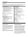
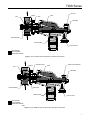
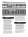
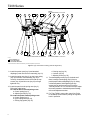
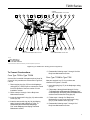
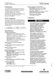
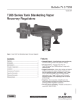
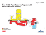
T208 Series
Instruction Manual
April 2014
T208 Series Tank Blanketing Vapor
Recovery Regulators
Table of Contents
Introduction................................................................... 1
Specifications............................................................... 2
Principle of Operation................................................... 2
Installation.................................................................... 4
Startup, Adjustment and Shutdown.............................. 5
Maintenance................................................................. 6
Parts Ordering............................................................ 11
Parts List.................................................................... 11
Figure 1. Type T208 Tank Blanketing Vapor Recover Regulator
!
Warning
Failure to follow these instructions or
to properly install and maintain this
equipment could result in an explosion,
fire and/or chemical contamination
causing property damage and personal
injury or death.
maintenance procedures performed
by unqualified person may result
in improper adjustment and unsafe
operation. Either condition may result in
equipment damage or personal injury.
Only a qualified person shall install or
service the T208 Series vapor
recovery regulator.
Fisher® Vapor Recovery regulators must
be installed, operated, and maintained
in accordance with federal, state and
local codes, rules and regulations,
and Emerson Process Management
Regulator Technologies Inc. (Regulator
Technologies) instructions.
Introduction
If the regulator discharges process
fluid or a leak develops in the system,
service to the unit may be required.
Failure to correct trouble could result in
a hazardous condition.
This Instruction Manual provides instructions for
installation, startup, maintenance and parts ordering
information for the T208 Series vapor recovery
regulators. Instructions and parts list for other
equipment used with these regulators are found in
separate manuals.
D103752X012
Call a qualified service person to service
the unit. Installation, operation and
Scope of the Manual
logo here
www.fisherregulators.com
T208 Series
Specifications
The Specifications section on this page provides the ratings and other specifications for the T208 Series. Factory
specification such as type, maximum inlet pressure, maximum temperature, maximum outlet pressure, spring
range and orifice size are stamped on the nameplate fastened on the regulator at the factory.
Product Configurations
Type T208: Tank Blanketing Vapor Recovery
regulator with control pressure range of
2 inches w.c. to 7 psig / 5 mbar to 0.48 bar in six
different spring ranges and has internal pressure
registration requiring no control line.
Type T208M: Similar to Type T208 but has a
blocked throat and a control line connection for
external pressure registration.
Body Sizes and End Connection Styles
See Table 1
Maximum Allowable Inlet (Casing) Pressure(1)
See Table 1
Maximum Outlet Pressure(1)
35 psig / 2.4 bar
Maximum Emergency Inlet Pressure to Avoid
Internal Parts Damage(1)
With Nitrile (NBR) or Fluorocarbon (FKM)
diaphragm: 35 psig / 2.4 bar
With Fluorinated Ethylene Propylene (FEP)
diaphragm: 10 psig / 0.69 bar
Control Pressure Ranges(1)
See Table 2
Shutoff Classification per ANSI/FCI 70-3-2004
Class VI (Soft Seat)
Pressure Registration
Type T208: Internal
Type T208M: External
Material Temperature Capabilities(1)(2)
Elastomer Parts
Nitrile (NBR): -40 to 180°F / -40 to 82°C
Fluorinated Ethylene Propylene (FEP):
-20 to 180°F / -29 to 82°C
Fluorocarbon (FKM): 40 to 300°F / 4 to 149°C
Ethylene Propylene Diene (EPDM):
-20 to 225°F / -29 to 107°C
Perfluoroelastomer (FFKM): 0 to 300°F /
-18 to 149°C
Body Materials
Gray Cast Iron: -20 to 300°F / -29 to 149°C
WCC Carbon Steel: -20 to 300°F / -29 to 149°C
CF8M/CF3M Stainless Steel:
-40 to 300°F / -40 to 149°C
Spring Case Vent Connection
1/4 NPT
Diaphragm Case Control Line Connection
(Type T208M)
1/2 NPT
Approximate Weight
17.7 pounds / 8 kg
1. The pressure/temperature limits in this Instruction Manual and any applicable standard or code limitation should not be exceeded.
2. See Table 4 for operating temperature ranges for available trim combinations.
Product Description
Principle of Operation
The T208 Series vapor recovery regulators are directoperated. They are used to sense an increase in
vessel pressure and vent excessive internal vessel
pressure to an appropriate vapor recovery disposal
or reclamation system. They may also be used as
backpressure regulators or relief valves.
The T208 Series vapor recovery regulators are used
to maintain a constant inlet (blanket) pressure with
the outlet flowing to a system whose pressure is
lower than that at the inlet. When vessel pressure
increases above the setpoint of the regulator due
to pumping in or thermal heating, the force of the
control spring is overcome by pressure acting on
the diaphragm. This moves the disk away from
the orifice, allowing gas to flow from the vessel to
the vapor recovery system. As vessel pressure is
reduced, the force of the back disk spring causes the
disk to move toward the orifice, decreasing the flow of
gas out of the vessel. As vessel pressure drops below
the setpoint of the regulator, the disk will seat against
the orifice, shutting off the gas flow.
Type T208—The Type T208 has internal registration
requiring no control line.
Type T208M—The Type T208M has a blocked throat
and a control line connection for external registration.
2
T208 Series
PIPE PLUG
ORIFICE
DISK
LEVER
STEM
DIAPHRAGM
BACK DISK SPRING
CONTROL SPRING
TYPE Y602-1 VENT
ERSA02737
INLET PRESSURE
OUTLET PRESSURE
ATMOSPHERIC PRESSURE
TYPE T208 WITH INTERNAL REGISTRATION
Figure 2. Type T208 with Internal Registration Operational Schematics
STEM SEAL O-RING
ORIFICE
DISK
LEVER
CONTROL LINE CONNECTION
DIAPHRAGM
THROAT SEAL
BACK DISK SPRING
CONTROL SPRING
TYPE Y602-1 VENT
ERSA02738
ERSA02737 INLET
PRESSURE
OUTLET
PRESSURE
INLET PRESSURE
OUTLET PRESSURE
ATMOSPHERIC
PRESSURE
ATMOSPHERIC PRESSURE
TYPE T208M WITH EXTERNAL REGISTRATION
TYPE T208 WITH INTERNAL REGISTRATION
Figure 3. Type T208M with External Registration Operational Schematics
3
T208 Series
Table 1. Body Sizes, End Connection Styles and Maximum Allowable Inlet (Casing) Pressures
Body size
Inch
3/4 or 1
DN
20 or 25
Maximum ALLOWABLE inlet (CASING) pressure
Body Material
End connection
styles(1)
psig
bar
Gray cast iron
NPT
35
2.4
WCC Carbon steel
NPT, CL150 RF, CL300 RF,
or PN 16/25/40 RF
75
5.2
CF8M/CF3M Stainless steel(2)
1. All flanges are welded. Weld-on flange dimension is 14 inches / 356 mm face-to-face.
2. Pipe nipples and flanges are 316 Stainless steel for flanged body assemblies.
Table 2. Control Pressure Ranges and Spring Information
Control pressure range
Spring part number
Spring color
Spring wire diameter
Spring free length
Inch w.c.
mbar
Inch
mm
Inch
mm
2 to 7(1)(2)
5 to 17(1)(2)
1B653827052
Red
0.085
2.2
3.63
92.2
3 to 13(1)(2)
7 to 32(1)(2)
1B653927022
Unpainted
0.105
2.7
3.75
95.3
10 to 26
25 to 65
1B537027052
Yellow
0.114
2.9
4.31
109
0.9 to 2.5 psig
62 to 172
1B537127022
Green
0.156
4.0
4.06
103
1.3 to 4.5 psig
90 to 310
1B537227022
Light blue
0.187
4.8
3.94
100
3.8 to 7 psig
0.26 to 0.48 bar
1B537327052
Black
0.218
5.5
3.98
101
1. To achieve the published control pressure range, the spring case must be installed pointing down.
2. Do not use Fluorocarbon (FKM) diaphragm with this spring at diaphragm temperatures lower than 60°F / 16°C.
Installation
!
Warning
Personal injury, property damage,
equipment damage or leakage due to
escaping gas or bursting of pressurecontaining parts may result if this
regulator is overpressured or installed
where service conditions could exceed
the limits given in the Specifications
section (page 2) or where conditions
exceed any ratings of the adjacent
piping or piping connections.
To avoid such injury or damage, provide
pressure-relieving or pressure-limiting
devices (as required by the appropriate
code, regulation or standard) to prevent
service conditions from exceeding limits.
Additionally, physical damage to the
regulator could cause personal injury or
property damage due to escaping gas.
To avoid such injury or damage, install
the regulator in a safe location.
1. Only personnel qualified through training and
experience shall install, operate and maintain
a regulator. For a regulator that is shipped
separately, make sure there is no damage to or
debris in the regulator. Also ensure that all tubing
and piping are clean and unobstructed.
4
2. Install the regulator using a straight run of pipe the
same size or larger as the regulator body. Flow
through the regulator body is indicated by the
flow arrow attached to the body. If a block valve
is required, install a full flow valve between the
regulator and the blanketed vessel. For proper
operation, the regulators should be installed with
the spring case barrel pointed down. Key numbers
referenced in this section are shown in Figures 4,
5 and 6.
!
Warning
A regulator may vent some gas to the
atmosphere. In hazardous or flammable
gas service, vented gas may accumulate
and cause personal injury, death or
property damage due to fire or explosion.
Vent a regulator in hazardous gas service
to a remote, safe location away from air
intakes or any hazardous area. The vent
line or stack opening must be protected
against condensation or clogging.
3. To keep the vent assembly (key 26) from being
plugged or the spring case (key 3) from collecting
moisture, corrosive chemicals or other foreign
material, point the vent down or otherwise
protect it. The diaphragm casing (key 4,
Figure 6) may be rotated in order to obtain
desired positioning.
T208 Series
4. To remotely vent the regulator, remove the vent
assembly (key 26) and install obstruction-free
tubing or piping into the 1/4 NPT vent tapping.
Provide protection on a remote vent by installing
a screened vent cap into the remote end of the
vent pipe. If continuous operation of the system is
required during inspection or maintenance, install
a three-way bypass valve around the regulator.
5. The Type T208M requires a control line. Be sure to
install the control line before putting the regulator
into operation. Make the control line as short
and straight as possible and do not install it in a
location where flow may be turbulent. Significant
restrictions in the control line can prevent proper
pressure registration. When using a hand valve, it
should be a full flow valve, such as a full port ball
valve. Install the control line sloping downward
toward the tank to prevent condensation buildup
and avoid low points (or traps) that could catch
liquid. The sensing line must enter the tank
above the liquid level at a point that senses the
vapor space pressure and is free from turbulence
associated with tank nozzles or vents. The control
line pipe should be at least 1/2-inch / 13 mm in
diameter and increase 1 pipe size for every
10 feet / 3.05 m of control line, with setpoint less
than 5-inches w.c / 12 mbar.
6. Vapor recovery regulators are used to maintain
a constant inlet (blanket) pressure with the outlet
flowing to a system whose pressure is lower than
that at the inlet. The recovery regulators are not
intended to be used as an ASME certified relief
device for overpressure protection on a tank. They
are to be used as part of a gas blanketing system
to control outflow of blanketing gas under normal
conditions and collect tank vapors for the vapor
disposal reclamation system. Provide alternate
methods of emergency overpressure protection.
Startup, Adjustment and Shutdown
Note
The Specifications section and Table 1
provide the maximum pressure
capabilities for each regulator
construction. Use pressure gauges
to monitor inlet pressure and control
pressure during startup.
Startup
1. Slowly open the outlet block valve, if used, to
vapor recovery system and leave it fully open.
2. Slowly open the shutoff valve (for Type T208M,
open the control line shutoff valve first followed by
the inlet shutoff valve) between the tank and vapor
recovery regulator.
3. Use gauges to monitor pressure.
Adjustment
!
Warning
To avoid personal injury, property
damage, or equipment damage caused
by bursting of pressure containing
parts or explosion of accumulated
gas, never adjust the control spring to
maintain a control pressure higher than
the upper limit of the control pressure
range for that particular spring. If the
desired control pressure is not within
the range of the spring, install a spring
of the proper range according to the
Diaphragm and Spring Case Area
section of the maintenance procedure.
Adjust the regulator control pressure setting to meet
the requirements of the specific application. The range
of allowable pressure setting is stamped on the
nameplate. If a pressure setting beyond the stamped
range is required, install a spring with the desired
range by following the procedures for changing
the spring in the Maintenance section. To adjust
the pressure setting, perform the following steps
(key numbers are referenced in Figures 4, 5 and 6).
For internal flat circular adjusting screw
1. Remove the closing cap (key 22).
2. Use a 1-inch / 25 mm hex rod or flat screwdriver
to turn the adjusting screw (key 35) either clockwise
to increase control pressure or counterclockwise to
decrease control pressure. The regulator will go into
immediate operation. To ensure correct operation,
always use a pressure gauge to monitor the vapor
recovery pressure when making adjustments.
3. After making the adjustment, replace the closing
cap gasket (key 25) and install the closing cap
(key 22).
5
T208 Series
For external square head adjusting screw
1. Loosen the locknut (key 20).
2. Turn the adjusting screw (key 35) either clockwise
to increase outlet pressure or counterclockwise to
decrease outlet pressure. The regulator will go into
immediate operation. To ensure correct operation,
always use a pressure gauge to monitor the vapor
recovery pressure when making adjustments.
3. After making the adjustment, tighten the locknut
(key 20).
Shutdown
1. Close the nearest upstream shutoff valve.
2. Close the nearest downstream shutoff valve to
vent the regulator properly.
3. Open the vent valve on both the upstream and
downstream sides of the regulator. All pressure
between these shutoff valves is released through
the open vent valve. For a regulator with control
line, close the valve in the control line and vent
the diaphragm casing to the atmosphere.
Maintenance
Regulator parts are subject to normal wear and must be
inspected and replaced as necessary. The frequency
of inspection and replacement of parts depends upon
the severity of service conditions or the requirements
of local, state and federal regulations. Due to the
care Regulator Technologies takes in meeting all
manufacturing requirements (heat treating, dimensional
tolerances, etc.), use only replacement parts
manufactured or furnished by Regulator Technologies.
!
Warning
To avoid personal injury, property
damage or equipment damage caused by
sudden release of pressure or explosion
of accumulated gas, do not attempt any
maintenance or disassembly without
first isolating the regulator from system
pressure and relieving all internal
pressure from the regulator.
Regulators that have been disassembled
for repair must be tested for proper
operation before being returned to
service. Only parts manufactured by
Regulator Technologies should be used
for repairing Fisher® regulators. Restart
6
gas utilization equipment according to
normal startup procedures.
General Maintenance
1. Visually inspect the regulator and its parts for
any damage.
2. Ensure tight connections, tight seals and safe
operation. If there is an evidence of leakage
or unstable internal motion, a rebuild with seal
replacement and relubrication may be necessary.
3. Observe the blanketing pressure.
4. Inspect the inlet pressure for the proper pressure
(stamped on the regulator nameplate).
Body Area
Perform the following procedure to gain access to the
disk assembly, orifice and body seal O-ring. Release
all pressure from the regulator before performing
the following steps. Key numbers are referenced in
Figures 4, 5 and 6.
1. To inspect and replace the disk assembly (key 13),
remove the back body cap (key 43).
2. Remove the disk assembly (key 13) from the disk
spacer (key 44) and replace if necessary.
3. To inspect the orifice (key 5) on Types T208 and
T208M or throat seal O-ring (key 31) and machine
screw (key 34) on the Type T208M, remove the
cap screws (key 2) and separate the diaphragm
casing (key 4) from the body (key 1).
4. Remove and inspect the body seal O-ring (key 11)
and the backup ring (key 49). Replace if damaged.
5. For a Type T208M, inspect the throat seal O-ring
(key 31) by removing the machine screw (key 34).
Replace if necessary. To install a throat seal, place
the throat seal O-ring on the machine screw and
thread into guide insert (key 18) to seal.
6. Inspect and replace the orifice (key 5) if necessary.
Lightly lubricate the threads of the replacement
orifice with a good quality lubricant and install
with 340 to 470 inch-pounds / 38.5 to 53.1 N•m
of torque.
7. Place back-up ring (key 49) into the body (key 1).
Then place the body seal O-ring (key 11) into
the body.
Note
In the following steps, be sure to install
the spring case barrel pointed down as
shown in Figure 1.
T208 Series
8. Place the diaphragm casing (key 4) on the body
(key 1). Secure the diaphragm casing to the body
with the cap screws (key 2) using 90 to
126 inch-pounds / 10.2 to 14.2 N•m of torque.
9. Secure the disk assembly (key 13) to the disk
spacer (key 44). Place the back disk spring
(key 41) and a new back body seal O-ring (key 42)
on the back body cap (key 43).
10. Lightly lubricate the threads when replacing the
body cap assembly. Use 340 to 470 inch-pounds /
38.5 to 53.1 N•m of torque.
Diaphragm and Spring Case Area
Perform the following procedure to gain access to the
spring, diaphragm, lever assembly and stem. Release
all pressure from the diaphragm casing before
performing the following steps. Key numbers are
referenced in Figures 4, 5 and 6.
To Change the Control Spring
For internal flat circular adjusting screw
1. Remove the closing cap (key 22) and closing cap
gasket (key 25). Turn the adjusting screw (key 35)
counterclockwise to remove all the compression from
the control spring (key 6).
2. Remove the adjusting screw (key 35) and
change the control spring (key 6) to match the
desired spring range.
3. Install the adjusting screw (key 35).
4. Adjust the outlet pressure to the desired control
pressure setting, refer to steps 2 and 3 of
Adjustment section.
5. Change the stamped spring range on the spring
case nameplate.
For external square head adjusting screw
1. Loosen the locknut (key 20) and turn the adjusting
screw (key 35) counterclockwise to remove all the
compression from the control spring (key 6).
2. Remove the adjusting screw (key 35), locknut
(key 20), closing cap (key 22), closing cap gasket
(key 25) and upper spring seat (key 19).
3. Take out the control spring (key 6) and replace
with the desired spring.
4. Reinstall the upper spring seat (key 19), closing
cap gasket (key 25), closing cap (key 22), locknut
(key 20) and adjusting screw (key 35).
5. Adjust the outlet pressure to the desired control
pressure setting, refer to steps 2 and 3 of
Adjustment section.
6. Change the stamped spring range on
the nameplate.
To Disassemble and Reassemble
Diaphragm Parts
Use this procedure to gain access to the control
spring, diaphragm assembly, valve stem and stem
O-ring. All pressure must be released from the
diaphragm case assembly before performing these
steps. Key numbers are referenced in Figures 4, 5
and 6.
1. For internal flat circular adjusting screw remove the closing cap (key 22), closing cap
gasket (key 25) and adjusting screw (key 35).
For external square head adjusting screw remove the adjusting screw (key 35), locknut
(key 20), closing cap (key 22), closing cap gasket
(key 25) and upper spring seat (key 19).
2. Remove the hex nuts (key 23) and cap screws
(key 24). Lift off the spring case (key 3) and
remove the control spring (key 6).
3. Remove the diaphragm (key 10) plus attached
parts by tilting them so that the pusher post
(key 8) slips off the lever assembly (key 16).
To separate the diaphragm assembly from the
attached parts, unscrew the cap screw (key 38)
from the pusher post. If the only maintenance
is to replace the diaphragm components, skip to
step 7.
4. To replace the lever assembly (key 16), remove
the machine screws (key 17). To replace the stem
(key 14) or stem seal O-ring (key 30), also perform
Body Area Maintenance procedure steps 1
through 3 and pull the stem (key 14) out of the
guide insert (key 18).
5. Install the stem (key 14) into the guide insert
(key 18) and perform Body Area Maintenance
procedure steps 7 through 10 as necessary.
6. Install the lever assembly (key 16) into the stem
(key 14) and secure the lever assembly with the
machine screws (key 17).
7. Reassemble the diaphragm parts as follows:
• Pusher post (key 8)
• Diaphragm head gasket (key 45)
• Diaphragm head (key 7)
• Diaphragm (key 10)
• Diaphragm head
• Lower spring seat (key 50)
• Washer (key 36)
Secure the parts with diaphragm plate cap screw
(key 38) using 60 to 72 inch-pounds / 6.8 to
8.1 N•m of torque.
7
T208 Series
TORQUE:
14 TO 19 INCH-POUNDS / 1.6 TO 2.1 N•m
L1
41
ERSA02737
42
13
44
L2
49
L1
5
14
11
18
L1
L2
12
17
35
TORQUE:
340 TO 470 INCH-POUNDS / 38.5 TO 53.1 N•m
38
16
6
8
36
45
50
7
7
10
9
TORQUE:
60 TO 72 INCH-POUNDS / 6.8 TO 8.1 N•m
APPLY LUBRICANT (L)(1):
L1 = Silicone Grease
L2 = ANTI-SEIZE COMPOUND
1. Lubricants must be selected such that they meet the temperature requirements.
Figure 4. Type T208 Section Drawing (Internal Registration)
8. Install the pusher post (key 8) and attached
diaphragm parts onto the lever assembly (key 16).
9. Install the spring case (key 3) on the lower casing
(key 4) so that the vent assembly (key 26) is
correctly oriented and secure them with the cap
screws (key 24) and hex nuts (key 23) to finger
tightness only.
10. Install the parts into the spring case (key 3).
Follow the order below:
For internal flat circular adjusting screw
a. Control spring (key 6)
b. Adjusting screw (key 35)
For external square head adjusting screw
a. Control spring (key 6)
b. Upper spring seat (key 19)
c. Closing cap gasket (key 25)
8
d. Closing cap (key 22)
e. Locknut (key 20)
f. Adjusting screw (key 35)
11. Turn the adjusting screw (key 35) clockwise until
there is enough control spring (key 6) force to
provide proper slack to diaphragm (key 10). Using
a crisscross pattern, finish tightening the cap
screws (key 24) and hex nuts (key 23) to 90 to
126 inch- pounds / 10.2 to 14.2 N•m of torque. Adjust
the control pressure to the desired pressure setting,
refer to the Adjustment section.
12. For Type T208M, connect the control line. Refer
to the Startup section before putting the regulator
back in operation.
T208 Series
TORQUE:
14 TO 19 INCH-POUNDS / 1.6 TO 2.1 N•m
L1
42
41
L2
44
5
49
34
L1
L1
11
31
L1
30
18
14
TORQUE:
340 TO 470 INCH-POUNDS / 38.5 TO 53.1 N•m
L1
12
17
16
8
L2
35
38
6
36
45
50
7
10
7
9
TORQUE:
60 TO 72 INCH-POUNDS / 6.8 TO 8.1 N•m
ERSA02738
APPLY LUBRICANT (L)(1):
L1 = Silicone Grease
L2 = ANTI-SEIZE COMPOUND
1. Lubricants must be selected such that they meet the temperature requirements.
Figure 5. Type T208M Section Drawing (External Registration)
To Convert Constructions
From Type T208 to Type T208M
A control line is needed. New parts required: keys 30,
31 and 34. Key numbers are referenced in Figures 4,
5 and 6.
1. Remove pipe plug (key 27) from the diaphragm
casing (key 4). Use this port to connect the control
line from upstream. See item number 5 in the
Installation section.
2. Refer to steps 1 through 3 in the Body Area
Maintenance section.
3. Insert the throat seal O-ring (key 31) and machine
screw (key 34).
4. Insert the stem seal O-ring (key 30) by following
steps 1 through 6 and 8 through 11 in the “To
Disassemble and Reassemble Diaphragm
Part” under Diaphragm and Spring Case Area
Maintenance section.
5. Reassemble following steps 7 through 10 of the
Body Area Maintenance section.
From Type T208M to Type T208
New part required: key 27. Key numbers are
referenced in Figures 4, 5 and 6.
1. Insert pipe plug (key 27) in the diaphragm casing
(key 4).
2. Follow steps 1 through 6 and 8 through 11 in the
“To Disassemble and Reassemble Diaphragm Part”
under Diaphragm and Spring Case Area Maintenance
section to remove the stem O-ring (key 30).
3. Follow steps 1 through 5 of Body Area
Maintenance to remove the throat seal O-ring
(key 31) and machine screw (key 34).
4. Reassemble following steps 7 through 10 of
Body Area Maintenance section.
9
H-POUNDS /
•m
T208 Series
22
25
3
22
46
25
26
3
47
46
24
26
48
47
TORQUE:
90 TO 126 INCH-POUNDS /
23
10.2 TO 14.2 N•m
24
43
23
27
27
4
TORQUE:
48 /
340 TO 470 INCH-POUNDS
38.5 TO 53.1 N•m
1
43
2
TORQUE:
90 to 126 INCH-POUNDS1/
10.2 to 14.2 N•m
2
4
TORQUE:
90 to 126 INCH-POUNDS /
10.2 to 14.2 N•m
35
20
35
20
22
19
22
19
L2
6
17
17A6570-B
SPRING CASE DOWNWARD (STANDARD)
TYPE Y602-1 VENT
L2
6
17A5515-D
17A6570-B
External Square Head Adjusting
Screw
Assembly
Option(2)
SPRING CASE
DOWNWARD
(STANDARD)
TYPE Y602-1 VENT
SPRING CASE UPWARD
TYPE Y602-11 VENT
ERSA02737
APPLY LUBRICANT (L)(1):
L2 = ANTI-SEIZE COMPOUND
1. Lubricant must be selected such that they meet the temperature requirements.
2. For 0.9 to 2.5 psig / 62 to 172 mbar, 1.3 to 4.5 psig / 90 to 310 mbar and 3.8 to 7 psig / 0.26 to 0.48 bar spring ranges only.
EXTERNAL SQUARE HEAD ADJUSTING SCREW ASSEMBLY OPTION(2)
Figure 6. Type T208 Assembly Drawing
EXTERNAL SQUARE HEAD ADJUSTING SCREW ASSEMBLY OPTION(2)
10
TORQUE:
340 TO 470 INCH-POUNDS /
38.5 TO 53.1 N•m
S
T208 Series
Parts Ordering
Key Description
When corresponding with your local Sales Office
about this regulator, include the type number and all
other pertinent information stamped on the nameplate.
Specify the 11-character part number when ordering
new parts from the following parts list.
Parts List
Key Description
Spare Parts Kit, included are keys 9, 10,
11, 12, 25, 42 and 45
(see Table 4 for Trim Option Codes)
Standard Trim
VV Trim
TN Trim
TV Trim TK Trim TE Trim Part Number
RT208XXDD12
RT208XXVV12
RT208XXTN12
RT208XXTV12
RT208XXTK12
RT208XXTE12
1 Body See Table 3
2 Cap Screw (2 required)
For Gray Cast Iron or WCC Carbon Steel Casing
1C856228992
For CF8M/CF3M Stainless Steel Casing
18B3456X012
3 Spring Case
Gray Cast Iron
ERSA02558A0
WCC Carbon Steel, NACE(2)ERSA00195A1
CF8M/CF3M Stainless Steel, NACE(2)ERSA00195A0
4
Lower Casing
Gray Cast Iron
47B2271X012
WCC Carbon Steel
ERSA00196A1
CF8M/CF3M Stainless Steel, NACE(2)ERSA00196A0
5* Orifice, 7/16-inch / 11 mm
Stainless Steel
0L0832X0012
6 Spring
See Table 2
7 Diaphragm Head (2 required)
Stainless Steel
17B9723X032
8 Pusher Post
For Nitrile (NBR) or Fluorocarbon (FKM) Diaphragm
Stainless Steel, NACE(2)18B3462X012
For Fluorinated Ethylene Propylene (FEP)
Diaphragm
Stainless Steel, NACE(2)ERSA00876A0
9 Diaphragm Gasket, Nitrile (NBR)
(For Fluorinated Ethylene
Propylene (FEP) Diaphragm)
ERSA00713A0
10* Diaphragm
Nitrile (NBR)
17B9726X012
Fluorocarbon (FKM)
23B0101X052
Fluorinated Ethylene Propylene (FEP)
ERSA00193A0
11* Body Seal O-ring
Nitrile (NBR)
1H993806992
Fluorocarbon (FKM)
1H9938X0012
Perfluoroelastomer (FFKM)
1H9938X0042
Ethylene Propylene Diene (EPDM)
1H9938X0022
12* Insert Seal O-ring
Nitrile (NBR)
1B885506992
Fluorocarbon (FKM)
1B8855X0012
Perfluoroelastomer (FFKM)
1B8855X0062
Ethylene Propylene Diene (EPDM)
1B8855X0022
13* Disk Assembly
Stainless Steel with
Nitrile (NBR) ERSA01112A0
Fluorocarbon (FKM) ERSA01112A1
Perfluoroelastomer (FFKM) ERSA01112A2
Ethylene Propylene Diene (EPDM) ERSA01112A3
Part Number
14 Stem, Stainless Steel
ERSA00200A0
16 Lever Assembly, Stainless Steel
1B5375000B2
17 Machine Screw (2 required)
Stainless Steel
19A7151X022
18 Guide Insert, Stainless Steel
27B4028X022
1J618124092
19 Upper spring seat(1), Steel
20 Lock Nut(1) 1A413224122
22 Closing Cap
Plastic (standard) T11069X0012
Steel
1E422724092
Stainless Steel
1E422735072
Carbon Steel(1)ERSA01809A0
23 Hex Nut (8 required)
For Gray Cast Iron or WCC Carbon Steel Casing
1A345724122
For CF8M/CF3M Stainless Steel Casing
1A3457K0012
24 Cap Screw (8 required)
For Gray Cast Iron or WCC Carbon Steel Casing
1A579724052
For CF8M/CF3M Stainless Steel Casing
1A5797T0012
25* Closing Cap Gasket, Neoprene (CR) 1P753306992
26 Vent Assembly
Spring Case Down (Type Y602-1) (standard)17A6570X012
Spring Case Up (Type Y602-11)
17A5515X012
27 Pipe Plug (Type T208 only) (not shown)
Carbon Steel (standard)1A369224492
Stainless Steel, NACE(2)1A369235072
30* Stem Seal O-ring (Type T208M only)
Nitrile (NBR) 1H2926G0012
Fluorocarbon (FKM) 1H2926X0022
Perfluoroelastomer (FFKM) 1H2926X0042
Ethylene Propylene Diene (EPDM) 1H2926X0012
31* Throat Seal O-ring (Type T208M only)
Nitrile (NBR) 1D682506992
Fluorocarbon (FKM) 1D6825X0012
Perfluoroelastomer (FFKM) 1D6825X0032
Ethylene Propylene Diene (EPDM) 1D6825X0042
34 Machine Screw (Type T208M only)
Stainless Steel 18A0703X022
35 Adjusting Screw
Internal Flat Circular (standard) 1B537944012
External Square Head(1)
For Green and Light blue spring
10B3080X012
For Black spring
1D995448702
36 Washer, Plated Carbon Steel
18B3440X012
38 Cap Screw, Zinc-plated Steel 1B290524052
41 Back Disk Spring
Stainless Steel 1E984637022
Inconel® , NACE(2)18B0255X012
42* Back Body Seal O-ring
Nitrile (NBR)
13A1584X012
Fluorocarbon (FKM)
13A1584X022
Perfluoroelastomer (FFKM)
13A1584X032
Ethylene Propylene Diene (EPDM)
13A1584X042
43 Back Body Cap
Stainless Steel 1F2737X0012
44 Disk Spacer
Stainless Steel ERSA00198A0
45* Diaphragm Head Gasket, Composition
18B3450X012
46 Nameplate
---------- 47 Drive screw, Stainless Steel (2 required)
1A368228982
48 Flow arrow
---------- 49 Backup Ring, Stainless Steel 18B3446X012
50 Lower Spring Seat, Zinc-plated Steel
1B636325062
51 NACE Tag
---------- 52 Tag Wire
-----------
*Recommended Spare Part
1. Use for optional external square head adjusting screw assembly recommended for 0.9 to 2.5 psig / 62 to 172 mbar, 1.3 to 4.5 psig / 90 to 310 mbar and 3.8 to 7 psig / 0.26 to 0.48 bar
spring ranges only.
2. NACE Standard MR0175-2002.
Inconel® is a mark owned by Special Metals Corporation.
11
T208 Series
Table 3. Body Materials and Part Numbers (Body, key 1)
Body material
End connection style(1)
Gray Cast Iron
WCC Carbon Steel
CF8M/CF3M Stainless Steel
(3)
Part number
3/4-Inch / DN 20 Body
1-Inch / DN 25 Body
NPT
ERSA03695A0
ERSA03697A0
NPT
ERSA00231A1
ERSA00764A1
CL150 RF
ERSA01470A0
ERSA01470A1
CL300 RF
ERSA01470A2
ERSA01470A3
PN 16/25/40 RF
ERSA01470A4
ERSA01470A5
NPT(2)
ERSA00231A0
ERSA00764A0
CL150 RF
ERSA01470A6
ERSA01470A7
CL300 RF
ERSA01470A8
ERSA01470A9
PN 16/25/40 RF
ERSA01470B0
ERSA01470B1
1. All flanges are welded. Weld-on flange dimension is 14 inches / 356 mm face-to-face.
2. NACE Standard MR0175-2002.
3. Pipe nipples and flanges are 316 Stainless steel for flanged body assemblies.
Table 4. Type T208 Trim Option Code
Trim Option Code
Diaphragm Material
Disk AND O-ring Material
Operating temperature ranges
-40 to 180°F / -40 to 82°C
Standard
Nitrile (NBR)
Nitrile (NBR)
VV
Fluorocarbon (FKM)
Fluorocarbon (FKM)
40 to 300°F / 4 to 149°C
TN
Fluorinated Ethylene Propylene (FEP)
Nitrile (NBR)
-20 to 180°F / -29 to 82°C
TV
Fluorinated Ethylene Propylene (FEP)
Fluorocarbon (FKM)
40 to 180°F / 4 to 82°C
TK
Fluorinated Ethylene Propylene (FEP)
Perfluoroelastomer (FFKM)
0 to 180°F / -18 to 82°C
TE
Fluorinated Ethylene Propylene (FEP)
Ethylene Propylene Diene (EPDM)
-20 to 180°F / -29 to 82°C
Industrial Regulators
Natural Gas Technologies
TESCOM
Emerson Process Management
Regulator Technologies, Inc.
Emerson Process Management
Regulator Technologies, Inc.
Emerson Process Management
Tescom Corporation
USA - Headquarters
McKinney, Texas 75070 USA
Tel: +1 800 558 5853
Outside U.S. +1 972 548 3574
USA - Headquarters
McKinney, Texas 75070 USA
Tel: +1 800 558 5853
Outside U.S. +1 972 548 3574
USA - Headquarters
Elk River, Minnesota 55330-2445, USA
Tels: +1 763 241 3238
+1 800 447 1250
Asia-Pacific
Shanghai 201206, China
Tel: +86 21 2892 9000
Asia-Pacific
Singapore 128461, Singapore
Tel: +65 6770 8337
Europe
Selmsdorf 23923, Germany
Tel: +49 38823 31 287
Europe
Bologna 40013, Italy
Tel: +39 051 419 0611
Europe
Bologna 40013, Italy
Tel: +39 051 419 0611
Chartres 28008, France
Tel: +33 2 37 33 47 00
Asia-Pacific
Shanghai 201206, China
Tel: +86 21 2892 9499
Middle East and Africa
Dubai, United Arab Emirates
Tel: +011 971 4811 8100
Middle East and Africa
Dubai, United Arab Emirates
Tel: +011 971 4811 8100
The distinctive diamond shape cast into every spring
case uniquely identifies the regulator as part of the
Fisher® brand and assures you of the highest-quality
engineering, durability, performance and support.
For further information visit www.fisherregulators.com
The Emerson logo is a trademark and service mark of Emerson Electric Co. All other marks are the property of their prospective owners. Fisher is a mark owned by Fisher Controls International LLC,
a business of Emerson Process Management.
The contents of this publication are presented for informational purposes only, and while every effort has been made to ensure their accuracy, they are not to be construed as warranties or
guarantees, express or implied, regarding the products or services described herein or their use or applicability. We reserve the right to modify or improve the designs or specifications of such
products at any time without notice.
Emerson Process Management Regulator Technologies, Inc. does not assume responsibility for the selection, use or maintenance of any product. Responsibility for proper selection, use and
maintenance of any Emerson Process Management Regulator Technologies, Inc. product remains solely with the purchaser.
©Emerson Process Management Regulator Technologies, Inc., 2013, 2014; All Rights Reserved