1
Bulletin 71.4:MR98
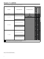
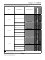
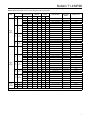
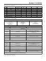
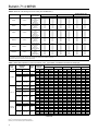
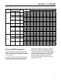
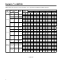
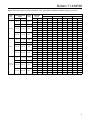
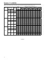
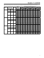
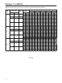
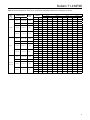
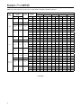
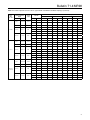
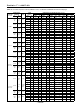
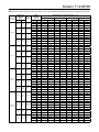
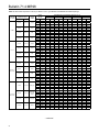
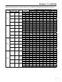
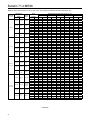
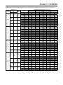
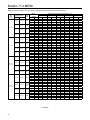
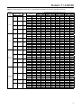
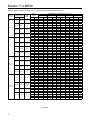
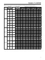
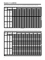
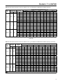
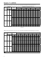
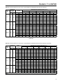
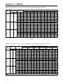
Typical relieving capacities in lbs per hour and kilogram
per hour of saturated steam are shown in Tables 9, 14
and 19.
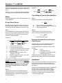
Equation 2:
QSCFH =
Tables 7, 8, 12, 13, 17 and 18 give relieving capacities in
U.S. gallons per minute and in liters per minute of water.
520
GT
CgP1aSIN
)
3417
C1
∆P
P1a
)
DEG
Liquid Sizing for Liquids Other than Water
Sizing
Determine Flow Rates for units used as differential relief
valves as follows:
Step 1.
Determine Cv at build-up conditions of application.
Cv =
Air and Steam Service
Q
∆P
When the Capacity Information section do not cover
the actual service conditions, it will be necessary to
calculate the flow rate available from the relief valve.
Q
∆P
Cv
Step 1.
Step 2. From the Capacity Information section determine a
flow rate using the closest available data for setpoint
and build-up. With this information, calculate a flow
coefficient using the following:
To determine flow rate for liquids other than water or flow rate for differential relief service:
Cg =
520
GT
Cg
Q
P1a
G
T
P1
C1
∆P
P1aSIN
)
Q
3417
C1
∆P
P1a
)
G = Specific gravity of fluid
Maximum Allowable Pressure Drop for
Liquid Service
DEG
= Calculated flow coefficient
= Flow rate from tables (SCFH)
= Inlet pressure from table (set pressure and build-up) converted to absolute pressure
= Specific gravity
= Absolute temperature of gas at inlet, °Rankine = °F + 460
= Absolute inlet pressure, psia = psig + 14.7
= See specifications section
= P1 - P2, psid
Calculate the Cg coefficient for the setting and build-up
nearest to the desired service conditions within the
selected spring range. Then use this Cg to calculate
the approximate flow available for the actual setpoint
and build-up desired. Available Cg will vary based
upon setpoint, differential pressure, build-up and
spring range.
Step 2.
Calculate the actual flow rate available using the
coefficient from Step 1 and the actual inlet pressure
(setpoint plus build-up) and actual outlet pressure
(if not atmospheric).
10
Q = Cv ∆P/G
Equation 1:
= Flow in gpm from capacity tables
= Pressure drop in psi (setpoint and build-up)
= Valve sizing coefficient
Pressure drops in excess of allowable will result in
choked flow and possible cavitation damage.
To determine maximum allowable pressure drop
for water:
∆P(allow)
∆P
Km
P1
= Km (P1)
= Valve differential - psi
= Valve recovery coefficient from table
= Valve inlet pressure psig
To determine maximum allowable pressure drop for
fluids other than water, see Fisher® Sizing Program.
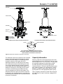
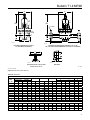
Installation
These valves may be installed in any position, as long
as flow will be in the same direction as that of the
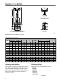
arrow cast on the body. For dimensional information
see Figure 4.
Emerson Process Management Regulator Technologies,
Inc. (Emerson™), provides an instruction manual
with every valves shipped. Refer to this for complete
installation, operation and maintenance instructions.
Included is a complete listing of individual parts and
recommended spare parts.