1
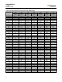
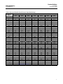
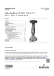
Product Bulletin Z500 Ball Valves 51.3:Z500 April 2015 - rev B D103992X012 Fisherr Z500 Severe Service Ball Valves This bulletin covers Fisher NPS 1/2 36 Z500 Severe Service Ball Valves. The Z500 severe service ball valve line is a simplistic two-piece floating ball design with integral metal seat meant to provide tight metal seating shutoff in high temperature, high pressure, and erosive applications across all industries. The mate lapped ball and seat constructions help ensure sealing and the high-velocity oxyfuel coatings (HVOF) provide excellent corrosion resistance and help eliminate the problems associated with severe service conditions. Z500 valves are available with a variety of end connections from ASME CL150 through CL4500. X1200 All Z500 valves are designed and manufactured to be used in severe service applications. They are highly engineered to help enhance safety in potentially dangerous operating parameters and reduce valve maintenance costs. Features n Machined Stops -- Integral 90 degree lockplate design prevents over-rotation and maintains critical alignment on lever-operated valves. n Side Mounted Bracket -- Helps prevent stem and packing box side load and bolt stress loads by attaching to the side of the valve body. n Live-Loaded Packing - Packing design utilizes live-loaded spring washers for easy adjustment. Compact stuffing box and liveloaded Belleville springs ensure packing is continuously energized and protects against stem side loading and temperature fluctuations. n Stem Adapter - Lever-operated valves have a contactproof stem adapter designed to prevent the stem from being knocked into the ball, causing misalignment and possible leakage. www.Fisher.com Typical Z500 Valves n BlowOut Proof Stem - Rugged, onepiece, machined, surface-hardened and polished stem is designed to be blowout proof. There are no pins to rely on, which helps increase safety and reliability. n Integral Metal Seat - Preferred sealing seat is machined into the end adapter, coated, and mate lapped with the ball. Design eliminates a potential leak path and helps the valve withstand high pressures, temperatures and severe service conditions. n Metal Body Gasket - Specially engineered, selfenergizing gasket helps ensure that there is no leakage during thermal transients. n High-Velocity Oxyfuel Coatings (HVOF) - Forms a very hard and dense coating on the base metal of the ball forming a strong mechanical bond. Typically these coatings are chromium or tungsten carbide. These coatings provide exceptional wear, corrosion, and erosion resistance. (continued on page 2) Product Bulletin Z500 Ball Valves 51.3:Z500 April 2015 - rev B D103992X012 Specifications Valve Sizes Z500: NPS J 1/2, J 3/4, J 1, J 1-1/2, J 2, J 3, J 4, J 6, J 8, J 10, J 12, J 14, J 16, J 18, J 20, J 24, J 26, J 28, J 30 and, J 36 Maximum Working Pressures(1) Forged Steel Valves: Consistent with applicable pressure-temperature ratings in table 1 per ASME B16.34, but do not exceed the material temperature capabilities shown below Shutoff Classification(1) Z500: Valves are tested to API 598 in the preferred flow direction. Class V type B per FCI 70-2 in reverse flow in bi-directional design (Must be specified). For other shutoff requirements, please contact your Emerson Process Management sales office. Construction Materials See table 2 Temperature Capabilities(1) Welded and Threaded Ends: SA105 - 800_F, F22 1000_F, F91 1200_F, F316 1400_F Flanged End Connections: SA105 - 600_F, F22 800_F, F91 1000_F, F316 1000_F Packing Constructions Carbon Steel Valve Bodies: Wire reinforced graphite stem packing, AISI 4130 nitrided packing gland Stainless Steel: Wire reinforced graphite stem packing, 316 SST nitrided packing gland Dimensions Contact your Emerson Process Management sales office Standard Flow Direction Preferred Flow Direction: Preferred flow for optimal sealing is forward into the integral seat Flow Coefficients Contact your Emerson Process Management sales office Maximum Ball Rotation 90 degrees Actuator Mounting The preferred mounting orientation is vertical. Other orientations are acceptable Approximate Weight Contact your Emerson Process Management sales office Options J Reduced port, J Double reduced ports, J Expanded outlet, J Scraper seats, J HVOF coating options, J Bi-directional sealing, J High cycle constructions, J Lockouts, J Spray and fused coatings 1. The pressure/temperature limits in this bulletin, and any applicable code or standard limitation, should not be exceeded. Features (continued) n Bi-Directional Sealing - Optional bi-directional sealing is available for all configurations but must be specified when ordering. Selecting this option designates reverse flow sealing to ANSI/FCI 70-2 Class V Type B shutoff classification. 2 n Sour Service Capability - Materials are available for applications involving sour liquids and gases. These constructions comply with NACE MR0103. n Back Pressure Protection - Welded and threaded end connection valves with 0.65, 1.15, and 1.5 inch bores come standard with a seat holder designed to protect the Belleville spring from being deformed in case of process back pressure. Product Bulletin Z500 Ball Valves 51.3:Z500 April 2015 - rev B D103992X012 Table 1. Valve Body Materials, End Connections, and Ratings Ratings Bore (inches) Size, NPS End Connection Valve Body Materials 1/2 0.65 3/4 1 1-1/2 1 1.15 1-1/2 2 Buttweld, Socketweld, FNPT, RF, RTJ 2-1/2 1-1/2 1.5 2 2 2-1/2 3 Buttweld, RF, RTJ 2 Buttweld, Socketweld, FNPT, RF, RTJ 2-1/2 3 4 Buttweld, RF, RTJ 3 CL150 through 1500 3 4 SA105, F22, F91, and F316 6 4 6 8 4 6 6 8 8 10 10 10 12 12 14 14 16 16 18 18 20 20 24 24 26 26 28 28 30 30 36 RF, RTJ 36 ‐continued‐ 3 Product Bulletin Z500 Ball Valves 51.3:Z500 April 2015 - rev B D103992X012 Table 1. Valve Body Materials, End Connections, and Ratings (continued) Ratings Bore (inches) Size, NPS End Connection Valve Body Materials 1/2 0.65 3/4 1 1-1/2 1 1.15 1-1/2 2 Buttweld, Socketweld, FNPT, RF, RTJ 2-1/2 1-1/2 1.5 CL2500 2 2 2-1/2 3 Buttweld, RF, RTJ 2 Buttweld, Socketweld, FNPT, RF, RTJ 2-1/2 3 4 SA105, F22, F91, and F316 Buttweld, RF, RTJ 3 3 4 6 4 6 8 4 6 RF, RTJ 6 8 8 10 1/2 0.65 3/4 1 1-1/2(1) 1 CL3200 and CL4500 1.15 1-1/2 Buttweld, Socketweld 2 2-1/2 1-1/2 1.5 2 2-1/2 3 1. Not available in CL4500. 4 Buttweld F22, F91, and F316 Product Bulletin Z500 Ball Valves 51.3:Z500 April 2015 - rev B D103992X012 Figure 1. Z500 Construction Features SEAT HOLDER STEM STEM BALL BALL BELLEVILLE SPRING UPSTREAM SEAT BELLEVILLE SPRING UPSTREAM SEAT X1209 X1206 UNI-DIRECTIONAL UPSTREAM SEAT DESIGN BI-DIRECTIONAL UPSTREAM SEAT DESIGN BODY GASKET UPSTREAM SEAT BELLEVILLE SPRING FLOW DIRECTION SEAT HOLDER INTEGRAL SEAT END ADAPTER BALL BODY GASKET VALVE BODY X1204 Z500 VALVE BODY CROSS SECTION 5 Product Bulletin Z500 Ball Valves 51.3:Z500 April 2015 - rev B D103992X012 Figure 2. Z500 Construction Features LOCKPLATE METAL BODY GASKET SUPPORT BUSHING (HIGH CYCLE BRACKET ONLY) SEAT HOLDER 1 STEM ADAPTER INTEGRAL METAL SEAT SIDE-MOUNTED BRACKET UPSTREAM SEAT BELLEVILLE SPRING END ADAPTER STEM PACKING STUD AND BELLEVILLE WASHERS PACKING GLAND BALL BODY STUD/NUT VALVE BODY X1207 Note: Seat holder is standard on welded and threaded end connections in 0.65, 1.15, and 1.5 inch bores only. Bidirectional option must be specified for all other 1 constructions. 6 Product Bulletin Z500 Ball Valves 51.3:Z500 April 2015 - rev B D103992X012 Table 2. Standard Construction Materials for NPS 1/2 through 36 Valves PART MATERIAL Balls F22, 316, F91, and 410 Bodies F22, SA105, F91, and F316 Upstream seats 410/F6A, F22, 316, and F91 Body gaskets S17400, N07718, S66286 Springs S17400, N07718, S66286 End adapter F22, SA105, F91, and F316 Coatings HVOF chromium carbide Packing Flexible graphite with S41000 stainless anti-extrusion rings Shafts (stem) S17400 nitrided, N07718 nitrided, S66286 nitrided (QPQ - quench polish quench) Key Zinc plated carbon steel Stem adapter AISI 4130, 4140 Seat Holder 410/F6A, F22, F316, and F91 Figure 3. Typical Z500 Packing Arrangement PACKING NUT PACKING STUD BELLEVILLE WASHERS GLAND PLATE ZERO CLEARANCE WASHERS GRAPHITE PACKING (PRESSED RINGS) ANTI-EXTRUSION RINGS (N06600 BRAIDED GRAPHITE) VALVE BODY X1208 ZERO CLEARANCE WASHERS VALVE STEM 7 Product Bulletin Z500 Ball Valves 51.3:Z500 April 2015 - rev B D103992X012 Pressure Drops Pressure drop limits of any given valve are based on valve body and material limits. Z500 valves meet full B16.34 pressure drop capabilities up to to specified material maximum temperature limit. Information on limits for other material constructions can be obtained by contacting your Emerson Process Management sales office. Table 3. Maximum Allowable Shutoff Pressure Drops (Body Ratings) TEMPERATURE RANGE PRESSURE CLASS SA105 CL150 SA105 CL300 SA105 CL600 SA105 CL900 SA105 CL1500 SA105 CL2500 SA105 CL4500 -29 to 38 19.7 51.0 102.0 153.1 93 17.9 46.9 255.5 425.4 766.0 93.8 140.3 234.1 389.9 149 15.9 702.2 45.2 90.3 135.5 225.5 375.8 204 676.7 13.8 43.8 87.2 131.0 218.6 364.0 655.3 260 11.7 41.7 83.1 124.8 207.9 346.5 623.3 316 9.7 39.3 78.3 117.6 195.8 326.1 587.1 343(1) 8.6 37.9 75.8 113.8 189.3 315.4 568.1 371(1) 7.6 36.5 71.0 109.6 183.7 305.1 548.8 399(1) 6.6 34.8 70.0 104.8 174.8 291.6 524.7 427(1) 5.5 28.3 56.9 85.2 141.7 236.5 425.4 _C Bar _F Psi -20 to 100 285 740 1480 2220 3705 6170 11110 200 260 680 1360 2035 3395 5655 10185 300 230 655 1310 1965 3270 5450 9815 400 200 635 1265 1900 3170 5280 9505 500 170 605 1205 1810 3015 5025 9040 600 140 570 1135 1705 2840 4730 8515 650(1) 125 550 1100 1650 2745 4575 8240 700(1) 110 530 1030 1590 2665 4425 7960 750(1) 95 505 1015 1520 2535 4230 7610 800(1) 80 410 825 1235 2055 3430 6170 1. Due to material limitations, consult your Emerson Process Management sales office for flanged end connection use over 316_C (600_F). 8 Product Bulletin Z500 Ball Valves 51.3:Z500 April 2015 - rev B D103992X012 Table 4. Maximum Allowable Shutoff Pressure Drops (Body Ratings) PRESSURE CLASS TEMPERATURE RANGE A182 Gr F22 Class 3 CL150 A182 Gr F22 Class 3 CL300 A182 Gr F22 Class 3 CL600 A182 Gr F22 Class 3 CL900 Bar A182 Gr F22 Class 3 CL1500 A182 Gr F22 Class 3 CL2500 A182 Gr F22 Class 3 CL4500 -29 to 38 20.0 51.7 103.4 155.1 258.6 430.9 775.7 93 17.9 51.7 103.4 155.1 258.6 430.9 775.7 149 15.9 50.3 100.3 150.7 251.0 418.5 753.3 204 13.8 48.6 97.2 145.8 243.4 405.4 729.8 260 11.7 45.9 91.7 137.6 229.3 382.0 687.1 316 9.7 41.7 83.4 125.1 208.6 347.5 625.4 343 8.6 40.7 81.0 121.7 202.7 338.2 608.5 371 7.6 39.3 78.3 117.6 195.8 326.1 587.1 399 6.6 36.5 73.4 110.0 183.4 305.4 549.5 427 5.5 35.2 70.0 105.1 175.1 291.6 524.7 454(1) 4.5 33.4 67.2 100.7 167.9 279.9 503.7 482(1) 3.4 31.0 62.1 93.1 154.8 258.2 464.7 510(1) 2.4 26.5 52.1 80.0 133.1 222.0 399.6 538(1) 1.4 18.3 36.9 55.2 92.0 153.8 276.5 _C _F Psi -20 to 100 290 750 1500 2250 3750 6250 11250 200 260 750 1500 2250 3750 6250 11250 300 230 730 1455 2185 3640 6070 10925 400 200 705 1410 2115 3530 5880 10585 500 170 665 1330 1995 3325 5540 9965 600 140 605 1210 1815 3025 5040 9070 650 125 590 1175 1765 2940 4905 8825 700 110 570 1135 1705 2840 4730 8515 750 95 530 1065 1595 2660 4430 7970 800 80 510 1015 1525 2540 4230 7610 850(1) 65 485 975 1460 2435 4060 7305 900(1) 50 450 900 1350 2245 3745 6740 950(1) 35 385 755 1160 1930 3220 5795 1000(1) 20 265 535 800 1335 2230 4010 1. Due to material limitations, consult your Emerson Process Management sales office for flanged end connection use over 427_C (800_F). 9 Product Bulletin Z500 Ball Valves 51.3:Z500 April 2015 - rev B D103992X012 Table 5. Maximum Allowable Shutoff Pressure Drops (Body Ratings) PRESSURE CLASS TEMPERATURE RANGE F316 Stainless Steel CL150 F316 Stainless Steel CL300 F316 Stainless Steel CL600 F316 Stainless Steel CL900 F316 Stainless Steel CL1500 F316 Stainless Steel CL2500 F316 Stainless Steel CL4500 -29 to 38 19.0 49.6 99.3 148.9 93 16.2 42.7 248.2 413.7 744.6 85.5 128.2 213.4 355.8 149 14.8 640.5 38.6 77.2 115.8 192.7 321.3 204 578.5 13.4 35.5 70.7 106.2 177.2 295.1 531.2 260 11.7 33.1 65.8 98.9 164.8 274.4 494.0 316 9.7 31.0 62.1 93.4 155.5 259.2 466.8 343 8.6 30.3 61.0 91.4 152.4 253.7 456.8 371 7.6 30.0 60.0 90.0 149.6 249.6 456.1 399 6.6 29.3 59.0 88.3 147.2 245.5 442.0 427 5.5 29.0 58.3 87.2 145.5 242.7 436.8 454 4.5 29.0 57.6 86.5 144.1 239.9 432.0 482 3.4 28.6 57.2 85.8 143.1 238.6 429.5 510 2.4 26.5 53.4 80.0 133.1 222.0 399.6 538 1.4 25.2 50.0 75.2 125.5 208.9 375.8 566(1) 1.4 11.0 49.6 74.5 124.1 206.8 372.3 593(1) 1.4 21.0 42.1 63.1 105.1 175.5 315.4 621(1) 1.4 16.2 32.8 49.0 81.7 135.8 244.8 649(1) 1.4 12.8 25.5 38.3 63.8 106.5 191.3 677(1) 1.4 10 20.3 30.3 50.7 84.8 145.5 704(1) 1.4 7.9 16.2 24.1 40.3 66.9 120.6 732(1) 1.4 6.6 13.1 20 33.1 55.2 99.3 760(1) 1.4 5.2 10.3 15.5 26.2 43.4 77.9 _C Bar _F Psi -20 to 100 275 720 1440 2160 3600 6000 10800 200 235 620 1240 1860 3095 5160 9290 300 215 560 1120 1680 2795 4660 8390 400 195 515 1025 1540 2570 4280 7705 500 170 480 955 1435 2390 3980 7165 600 140 450 900 1355 2255 3760 6770 650 125 440 885 1325 2210 3680 6625 700 110 435 870 1305 2170 3620 6615 750 95 425 855 1280 2135 3560 6410 800 80 420 845 1265 2110 3520 6335 850 65 420 835 1255 2090 3480 6265 900 50 415 830 1245 2075 3460 6230 950 35 385 775 1160 1930 3220 5795 1000 20 365 725 1090 1820 3030 5450 1050(1) 20 160 720 1080 1800 3000 5400 1100(1) 20 305 610 915 1525 2545 4575 1150(1) 20 235 475 710 1185 1970 3550 1200(1) 20 185 370 555 925 1545 2775 1250(1) 20 145 295 440 735 1230 2110 1300(1) 20 115 235 350 585 970 1750 1350(1) 20 95 190 290 480 800 1440 1400(1) 20 75 150 225 380 630 1130 1. Due to material limitations, consult your Emerson Process Management sales office for flanged end connection use over 538_C (1000_F). 10 Product Bulletin Z500 Ball Valves 51.3:Z500 April 2015 - rev B D103992X012 Table 6. Maximum Allowable Shutoff Pressure Drops (Body Ratings) TEMPERATURE RANGE PRESSURE CLASS A182 Gr F91 CL150 A182 Gr F91 CL300 A182 Gr F91 CL600 A182 Gr F91 CL900 A182 Gr F91 CL1500 A182 Gr F91 CL2500 A182 Gr F91 CL4500 -29 to 38 20.0 51.7 103.4 155.1 93 17.9 51.7 258.6 430.9 775.7 103.4 155.1 258.6 430.9 149 15.9 775.7 50.3 100.3 150.7 251.0 418.5 204 753.3 13.8 48.6 97.2 145.8 243.4 405.4 729.8 260 11.7 45.9 91.7 137.6 229.3 382.0 687.1 316 9.7 41.7 83.4 125.1 208.6 347.5 625.4 343 8.6 40.7 81.0 121.7 133.8 338.2 608.5 371 7.6 39.3 78.3 117.6 126.9 326.1 587.1 399 6.6 36.5 73.4 110.0 114.5 305.4 549.5 427 5.5 35.2 70.0 105.1 106.2 291.6 524.7 454 4.5 33.4 67.2 100.7 98.9 279.9 503.7 482 3.4 31.0 62.1 93.1 154.8 258.2 464.7 510 2.4 26.5 53.4 80.0 133.1 222.0 399.6 538 1.4 25.2 50.0 75.2 125.5 208.9 375.8 566(1) 1.4 24.8 49.6 74.5 124.1 206.8 448.2 593(1) 1.4 20.7 41.7 62.6 104.1 173.4 312.0 621(1) 1.4 15.5 30.7 46.2 76.9 127.9 230.6 649(1) 1.4 10.0 20.0 29.6 49.6 82.7 148.9 _C Bar _F Psi -20 to 100 290 750 1500 2250 3750 6250 11250 200 260 750 1500 2250 3750 6250 11250 300 230 730 1455 2185 3640 6070 10925 400 200 705 1410 2115 3530 5880 10585 500 170 665 1330 1995 3325 5540 9965 600 140 605 1210 1815 3025 5040 9070 650 125 590 1175 1765 1940 4905 8825 700 110 570 1135 1705 1840 4730 8515 750 95 530 1065 1595 1660 4430 7970 800 80 510 1015 1525 1540 4230 7610 850 65 485 975 1460 1435 4060 7305 900 50 450 900 1350 2245 3745 6740 950 35 385 775 1160 1930 3220 5795 1000 20 365 725 1090 1820 3030 5450 1050(1) 20 360 720 1080 1800 3000 6500 1100(1) 20 300 605 908 1510 2515 4525 1150(1) 20 225 445 670 1115 1855 3345 1200(1) 20 145 290 430 720 1200 2160 1. Due to material limitations, consult your Emerson Process Management sales office for flanged end connection use over 538_C (1000_F). 11 Product Bulletin 51.3:Z500 April 2015 - rev B Z500 Ball Valves D103992X012 Neither Emerson, Emerson Process Management, nor any of their affiliated entities assumes responsibility for the selection, use or maintenance of any product. Responsibility for proper selection, use, and maintenance of any product remains solely with the purchaser and end user. Fisher is a mark owned by one of the companies in the Emerson Process Management business unit of Emerson Electric Co. Emerson Process Management, Emerson, and the Emerson logo are trademarks and service marks of Emerson Electric Co. All other marks are the property of their respective owners. The contents of this publication are presented for informational purposes only, and while every effort has been made to ensure their accuracy, they are not to be construed as warranties or guarantees, express or implied, regarding the products or services described herein or their use or applicability. All sales are governed by our terms and conditions, which are available upon request. We reserve the right to modify or improve the designs or specifications of such products at any time without notice. Emerson Process Management Marshalltown, Iowa 50158 USA Sorocaba, 18087 Brazil Chatham, Kent ME4 4QZ UK Dubai, United Arab Emirates Singapore 128461 Singapore www.Fisher.com E 122015 Fisher Controls International LLC. All rights reserved.