1
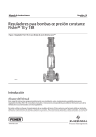
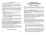
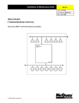
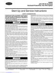
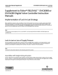
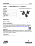
Instruction Manual
1B Actuator
D100639X012
April 2011
Fisherr 1B and 1BR Constant‐Pressure Pump
Governor Actuators
Figure 1. Fisher 1B Actuator on Direct‐Acting easy‐e™ Valve
W2232‐1
Introduction
Scope of Manual
This instruction manual provides information on installation, adjustment, maintenance, and parts ordering for the
Fisher 1B pump governor actuator. Refer to separate instruction manuals for information about the valve and other
accessories used with these actuators.
Do not install, operate, or maintain a 1B pump governor actuator without being fully trained and qualified in valve,
actuator, and accessory installation, operation, and maintenance. To avoid personal injury or property damage, it is
important to carefully read, understand, and follow all the contents of this manual, including all safety cautions and
www.Fisher.com
1B Actuator
April 2011
Instruction Manual
D100639X012
warnings. If you have any questions about these instructions, contact your Emerson Process Management sales office
before proceeding.
Description
The 1B pump governor actuator (figure 1) is used to maintain a constant discharge pressure on steam driven turbine
or reciprocating pumps and for pressure reducing or pressure relief applications. Typical pump governor applications
include fire pumps, boiler feedwater pumps, and industrial or refining pumps where the discharge medium is oil,
steam, air, or other noncorrosive fluid.
The 1BR pump governor actuator is combined with a push‐down‐to‐open valve for service as a relief governor. A relief
governor is used to divert excess pump discharge to the suction side of the pump.
Installation
WARNING
Always wear protective gloves, clothing, and eyewear when performing any installation operations to avoid personal
injury.
Personal injury or equipment damage caused by sudden release of pressure may result if the valve assembly is installed
where service conditions could exceed the limits given on the appropriate nameplates. To avoid such injury or damage,
provide a relief valve for over‐pressure protection as required by government or accepted industry codes and good
engineering practices.
Check with your process or safety engineer for any additional measures that must be taken to protect against process
media.
If installing into an existing application, also refer to the WARNING at the beginning of the Maintenance section in this
instruction manual.
CAUTION
When ordered, the valve configuration and construction materials were selected to meet particular pressure, temperature,
pressure drop, and controlled fluid conditions. Responsibility for the safety of process media and compatibility of valve
materials with process media rests solely with the purchaser and end‐user. Since some valve body/trim material
combinations are limited in their pressure drop and temperature ranges, do not apply any other conditions to the valve
without first contacting your Emerson Process Management sales office.
The 1B pump governor can be installed either above or below the line but if possible it should be installed above it.
CAUTION
Thoroughly clean and blow out all pipe scale and other foreign matter. It is recommended that a Fisher strainer be installed
in the line ahead of the main valve to protect the governor while in service.
If continuous operation is desired during inspection or maintenance, install a conventional three‐valve bypass around
the governor.
2
Instruction Manual
1B Actuator
D100639X012
April 2011
Refer to figure 2.
1. Using good piping procedure install the governor with flow in the direction of the arrow cast on the valve body.
2. Run a 1/4 inch control line from the top of the governor to the side or top of the pump discharge line, about 10 feet
from the pump. Install a pressure gauge and a large port needle valve in this line. Throttling this needle valve places
a restriction in the control line to smooth out operation.
Figure 2. Fisher 1B Installation
FISHER FRE-FLO STRAINER
FISHER 1B
PUMP GOVERNOR
NEEDLE VALVE
PUMP DISCHARGE
SUCTION
AC4650
Note
Before putting the governor into operation, be sure to remove the plastic shipping plug in the vent hole of the adaptor piece.
3. Open the gate valve on the downstream side and close the valve in the bypass line.
4. Slowly open the upstream gate valve.
5. Allow the governor sufficient time to assume normal operation before checking the controlled pressure. If the
governor is not controlling at the set point needed, make the necessary changes as directed in the section entitled
Adjustments.
Adjustments
The pump governor has been factory set for the operating conditions stated in the order. To change the pump
discharge, use the adjusting screw (key 3). To increase the discharge pressure, turn the adjusting screw into the yoke.
3
1B Actuator
April 2011
Instruction Manual
D100639X012
Pressure pulsation in the discharge line can be minimized by slightly closing the needle valve in the control line. Never
completely close the needle valve while the pump governor is in operation.
Maintenance
Actuator parts are subject to normal wear and must be inspected and replaced when necessary. The frequency of
inspection and replacement depends on the severity of service conditions.
WARNING
Avoid personal injury or property damage from sudden release of process pressure or bursting of parts. Before performing
any maintenance operations:
D Do not remove the actuator from the valve while the valve is still pressurized.
D Always wear protective gloves, clothing, and eyewear when performing any maintenance operations to avoid personal
injury.
D Disconnect any operating lines providing air pressure, electric power, or a control signal to the actuator. Be sure the
actuator cannot suddenly open or close the valve.
D Use bypass valves or completely shut off the process to isolate the valve from process pressure. Relieve process pressure
from both sides of the valve. Drain the process media from both sides of the valve.
D Vent the power actuator loading pressure and relieve any actuator spring precompression.
D Use lock‐out procedures to be sure that the above measures stay in effect while you work on the equipment.
D The valve packing box may contain process fluids that are pressurized, even when the valve has been removed from the
pipeline. Process fluids may spray out under pressure when removing the packing hardware or packing rings, or when
loosening the packing box pipe plug.
D Check with your process or safety engineer for any additional measures that must be taken to protect against process
media.
When performing maintenance procedures, isolate the control valve from the process line pressure, release pressure
from both sides of the valve body, and drain the process media from both sides of the valve. Use lock‐out procedures
to be sure that the above measures stay in effect while you are working on the actuator.
To Replace the Piston Cup:
1. Isolate the pump governor.
2. Remove the control line connection.
3. Unscrew the hex nuts (key 8).
4. Remove the cylinder cap (key 12).
5. Unscrew the cap screw (key 10) and remove the follower (key 6).
6. Remove the old piston cup (key 13) and install the new one.
7. Reassemble the pump governor in the following order: piston cup (key 13), follower (key 6), cap screw (key 10),
cylinder cap (key 12), and hex nuts (key 8).
4
Instruction Manual
1B Actuator
D100639X012
April 2011
Parts Ordering
Each actuator has a serial number stamped on the nameplate. Always mention this number when corresponding with
your Emerson Process Management sales office regarding technical information or replacement parts. Also, reference
the complete 11‐character part number of each needed part as found in the following Parts List.
WARNING
Use only genuine Fisher replacement parts. Components that are not supplied by Emerson Process Management should not,
under any circumstances, be used in any Fisher valve, because they may void your warranty, might adversely affect the
performance of the valve, and could cause personal injury and property damage.
Note
Neither Emerson, Emerson Process Management, nor any of their affiliated entities assumes responsibility for the selection, use, or
maintenance of any product. Responsibility for the selection, use, and maintenance of any product remains with the purchaser and
end user.
Parts List
Note
Part numbers are shown for recommended spares only. For part
numbers not shown, contact your Emerson Process Management sales
office.
Key
Description
1
2
2A
2B
2C
3
Yoke, iron
Piston Rod Assembly, Steel Zn Pl
Piston Rod
Pin
Piston
Adjusting Screw, Brass Chrome Pl
*Recommended spare parts
Part Number
Key
Description
4
6
7
8
9
10
11*
12
13*
14
15
16
17
18
19
20
21
Spring, Steel
Follower, Steel Zn Pl
Cylinder, Brass
Finished Hex Nut, Steel Zn Pl (6 req'd)
Stud Bolt, Steel, Zn Pl (6 req'd)
Cap Screw, Steel Zn Pl
Gasket, Composition
Cylinder Cap, Iron
Piston Cup, Nitrile
Adaptor Assembly
Hex Head Cap Screw, Steel Zn Pl (6 req'd)
Travel Stop, Steel Zn Pl (reverse‐acting only)
Spring Seat, (2 req'd)
Finished Hex Nut, Steel Zn Pl
Finished Hex Jam Nut, Steel Zn Pl
Name Plate, SST
Drive Screw, SST (4 req'd)
Part Number
1F640104022
1N575806992
5
1B Actuator
April 2011
Figure 3. Fisher 1B Assembly
BN5768
6
Instruction Manual
D100639X012
Instruction Manual
D100639X012
1B Actuator
April 2011
7
1B Actuator
April 2011
Instruction Manual
D100639X012
Fisher and easy-e are marks owned by one of the companies in the Emerson Process Management business division of Emerson Electric Co. Emerson
Process Management, Emerson, and the Emerson logo are trademarks and service marks of Emerson Electric Co. All other marks are the property of their
respective owners.
The contents of this publication are presented for informational purposes only, and while every effort has been made to ensure their accuracy, they are not
to be construed as warranties or guarantees, express or implied, regarding the products or services described herein or their use or applicability. All sales
are governed by our terms and conditions, which are available upon request. We reserve the right to modify or improve the designs or specifications of
such products at any time without notice. Neither Emerson, Emerson Process Management, nor any of their affiliated entities assumes responsibility for the
selection, use or maintenance of any product. Responsibility for proper selection, use, and maintenance of any product remains solely with the purchaser
and end user.
Emerson Process Management
Marshalltown, Iowa 50158 USA
Sorocaba, 18087 Brazil
Chatham, Kent ME4 4QZ UK
Dubai, United Arab Emirates
Singapore 128461 Singapore
www.Fisher.com
8
EFisher
Controls International LLC 1997, 2011; All Rights Reserved