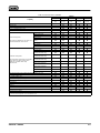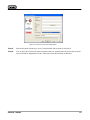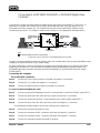
1
Installation Guide
D102800X012
October 2010
Installing ValveLink Software
ValveLink Solo
AMS ValveLink SNAP-ON
ValveLink DTM
ValveLink PLUG-IN for PRM
www.Fisher.com
This page intentionally left blank.
Comment Form
ValveLink Software Installation Guide
The ValveLink Software Installation Guide is intended to provide the basic
information you need to install ValveLink software and associated hardware and
software. Detailed information about ValveLink software is provided in the online help.
Please give us your feedback to help us improve this guide.
Did you use this manual to:
Yes
No
Install ValveLink Solo?
_____
_____
Install AMS ValveLink SNAP-ON?
_____
_____
Install ValveLink DTM?
_____
_____
Install ValveLink Plug-In for PRM?
_____
_____
Install the hardware key or a software
license key using the License Wizard?
_____
_____
Install HART modem?
_____
_____
Install HART multiplexer?
_____
_____
Install FOUNDATION fieldbus
hardware and software?
_____
_____
Setup a Modbus Network?
_____
_____
Could you easily find the answers to your
questions in this manual?
_____
_____
Could you easily find the answers to your
questions In the ValveLink software
online help?
_____
_____
How can we make this manual more useful to you?_____________________________
______________________________________________________________________
Identify any areas that you found difficult to understand._________________________
______________________________________________________________________
______________________________________________________________________
Other comments: _______________________________________________________
______________________________________________________________________
______________________________________________________________________
May we contact you about your comments?
Yes
No
_____
_____
Name_________________________________________________________
Company______________________________________________________
Phone________________________________________________________
Date__________________________________________________________
Thank you for your comments. Fold and mail
this form to Fisher Controls International LLC
___________________________________________
Name______________________________________
Company___________________________________
Address____________________________________
Fisher Controls International LLC
301 S. 1st Avenue
Marshalltown, IA 50158
c/o FIELDVUE Software Product
Manager
Table of Contents
Introduction . . . . . . . . . . . . . . . . . . . . . . . . . . . . . . . . . . . . . 1-1
What is ValveLink Software? . . . . . . . . . . . . . . . . . . . . . 1-3
About this Guide . . . . . . . . . . . . . . . . . . . . . . . . . . . . . . . 1-3
Organization . . . . . . . . . . . . . . . . . . . . . . . . . . . . . . . . . . . 1-4
Before Installing ValveLink Software . . . . . . . . . . . . . . 1-5
Technical Support . . . . . . . . . . . . . . . . . . . . . . . . . . . . . . 1-6
Related Documents . . . . . . . . . . . . . . . . . . . . . . . . . . . . . 1-7e
Prerequisites and Requirements . . . . . . . . . . . . . . 2-1
“Before You Begin” Information . . . . . . . . . . . . . . . . . . . 2-2
Installation Tools and Device Documentation . . . . . . . 2-3
Personal Computer Requirements . . . . . . . . . . . . . . . . 2-4
Compatible Devices . . . . . . . . . . . . . . . . . . . . . . . . . . . . 2-7
Installing ValveLink Solo . . . . . . . . . . . . . . . . . . . . . . . 3-1
ValveLink Solo Installation Overview . . . . . . . . . . . . . . 3-2
Installing the Software . . . . . . . . . . . . . . . . . . . . . . . . . . 3-4
Re-installing the Software . . . . . . . . . . . . . . . . . . . . . . . 3-6
Installing AMS ValveLink SNAP-ON . . . . . . . . . . . 4-1
AMS ValveLink SNAP-ON Installation Overview . . . . 4-2
Installing AMS ValveLink SNAP-ON . . . . . . . . . . . . . . 4-3
Starting AMS ValveLink SNAP-ON . . . . . . . . . . . . . . . 4-4
Installing ValveLink DTM . . . . . . . . . . . . . . . . . . . . . . . 5-1
ValveLink DTM
Installation Overview . . . . . . . . . . . . . . . . . . . . . . . . . . . 5-2
Installing ValveLink DTM . . . . . . . . . . . . . . . . . . . . . . . . 5-3
Starting ValveLink DTM . . . . . . . . . . . . . . . . . . . . . . . . . 5-4
Installing ValveLink PLUG-IN
for PRM . . . . . . . . . . . . . . . . . . . . . . . . . . . . . . 6-1
ValveLink PLUG-IN for PRM Installation Overview . . 6-2
Installing ValveLink PLUG-IN for PRM . . . . . . . . . . . . 6-3
Starting ValveLink PLUG-IN for PRM . . . . . . . . . . . . . 6-6
License Wizard . . . . . . . . . . . . . . . . . . . . . . . . . . . . . . . . . 7-1
ValveLink License Wizard . . . . . . . . . . . . . . . . . . . . . . . 7-2
ValveLink Software
Enabling the License of Installed Software . . . . . . . . . 7-3
Attaching the Hardware Key . . . . . . . . . . . . . . . . . . . . . 7-4
Obtaining a Software License Key for a
Fresh Installation . . . . . . . . . . . . . . . . . . . . . . . . . . . . . . 7-4
Adding Features to the Installed Software . . . . . . . . . 7-8
Obtaining a Software License Key for a StepUp . . . . 7-9
Removing a License . . . . . . . . . . . . . . . . . . . . . . . . . . . . 7-11
Transferring a License to Another Computer . . . . . . . 7-12
Updating a Hardware Key . . . . . . . . . . . . . . . . . . . . . . . 7-13
Enabling a Temporary License . . . . . . . . . . . . . . . . . . . 7-14
Entering a License Key . . . . . . . . . . . . . . . . . . . . . . . . . . 7-15
HART Modem Installation for
ValveLink Solo . . . . . . . . . . . . . . . . . . . . . . 8-1
Attaching the HART Modem . . . . . . . . . . . . . . . . . . . . . 8-2
Multiplexer Networks for ValveLink
Solo . . . . . . . . . . . . . . . . . . . . . . . . . . . . . . . . . . 9-1
Setting Up a Multiplexer Network . . . . . . . . . . . . . . . . . 9-2
Changing the Multiplexer Tag and Descriptor . . . . . . . 9-4
Setting Up the Pepperl+Fuchs Multiplexer . . . . . . . . . 9-5
Viewing Multiplexers Status . . . . . . . . . . . . . . . . . . . . . . 9-6
Adding Instruments to a Multiplexer . . . . . . . . . . . . . . . 9-8
ValveLink Software
Installing Software and Hardware for
Communication with FOUNDATION
fieldbus Instruments for ValveLink
Solo . . . . . . . . . . . . . . . . . . . . . . . . . . . . . . . . . . . . . . . . . 10-1
NI-FBUS Installation . . . . . . . . . . . . . . . . . . . . . . . . . . . . 10-2
Software . . . . . . . . . . . . . . . . . . . . . . . . . . . . . . . . . . . . 10-2
Hardware . . . . . . . . . . . . . . . . . . . . . . . . . . . . . . . . . . . 10-2
Configuring the PCMCIA-FBUS Card . . . . . . . . . . . . . 10-3
Checking for IRQ and Memory Conflicts . . . . . . . . . . . 10-6
Installing Device Descriptions (DD) . . . . . . . . . . . . . . . 10-7
Connecting to a FOUNDATION Fieldbus Segment . . . . 10-9
Connecting to a Single DVC5000f, DVC6000f or
DVC6200f Instrument . . . . . . . . . . . . . . . . . . . . . . . . . . 10-11
Modbus Networks for ValveLink
Solo . . . . . . . . . . . . . . . . . . . . . . . . . . . . . . . . . . 11-1
Setting Up the Modbus Network . . . . . . . . . . . . . . . . . . 11-2
Troubleshooting Installation . . . . . . . . . . . . . . . . . . . 12-1
Troubleshooting Communication . . . . . . . . . . . . . 13-1
Appendix A Modbus Protocol . . . . . . . . . . . . . . . . . A-1
Glossary
Index
ValveLink Software
ValveLink Software
Introduction11
Section 1
This section is an overview of ValveLink software and this guide.
What is ValveLink Software? . . . . . . . . . . . . . . . . . . . . . 1-2
About this Guide . . . . . . . . . . . . . . . . . . . . . . . . . . . . . . . 1-3
Organization . . . . . . . . . . . . . . . . . . . . . . . . . . . . . . . . . . . 1-4
Before Installing ValveLink Software . . . . . . . . . . . . . . 1-5
Technical Support . . . . . . . . . . . . . . . . . . . . . . . . . . . . . . 1-6
Related Documents . . . . . . . . . . . . . . . . . . . . . . . . . . . . . 1-7e
ValveLink Software
1-1
What is ValveLink Software?
ValveLink software is a Windows software package that communicates with HART and
FOUNDATION fieldbus FIELDVUE digital valve controllers. ValveLink software supports access
to the information available from DVC2000, DVC6000, DVC6000f, DVC6200, and DVC6200f
digital valve controllers, and obsolete DVC5000 and DVC5000f digital valve controllers.
ValveLink Software:
Communicates with HART instruments (DVC2000, DVC5000, DVC6000 and DVC6200)
over the existing 4-20 milliamp (mA) signal wiring via either HART modem or HART
multiplexer.
Communicates with FOUNDATION fieldbus instruments (DVC5000f, DVC6000f, and
DVC6200f ) over the fieldbus H1 segment via a National Instruments communications card or
National Instruments USB fieldbus interface.
Integrates data from the HART instruments into a Modbus-compatible host system.
Batch Runner or Scheduler automate repetitive actions.
Accesses real-time instrument status and diagnostic data.
Overlays current diagnostic test displays with Signature Series test data collected when
the valve was new.
Monitors control performance during process operations using ValveLink software
trending capabilities.
Maintains a central database and synchronizes other databases using the DataSync
tool.
Supports the automated adjustment of digital valve controller performance using the
Performance Tuner.
Provides a detailed event log through AuditLog.
PD Performance Diagnostics provide in-service diagnostics for monitoring the health of
the valve assembly without disturbing the process
1-2
ValveLink Software
About This Guide
This installation guide contains easy-to-follow instructions that will guide you through the
installation of communications hardware and ValveLink software. Refer to the help system for
ValveLink software functions.
Scope
This guide describes:
Installing ValveLink software. Includes ValveLink Solo, AMS ValveLink SNAP-ON,
ValveLink DTM, and ValveLink PLUG-IN for PRM.
Using License Wizard to enable the license of your ValveLink software, either with a
USB hardware key or a software license key.
Installing the National Instruments FOUNDATION fieldbus interface software and hardware.
Making HART and FOUNDATION fieldbus instrument connections.
Setting up multiplexer networks.
Setting up Modbus networks.
Troubleshooting Installation
Troubleshooting Communication
For more detailed information on any of these features, see ValveLink software help.
Customer Feedback Form
Please take a moment to fill out the Customer Feedback Form and return it.
ValveLink Software
1-3
Organization
This guide is organized into the following sections:
Section 1, Introduction, describes ValveLink software and this installation guide for
ValveLink Solo, AMS ValveLink SNAP-ON, ValveLink DTM, and ValveLink PLUG-IN for
PRM.
Section 2, Prerequisites and Requirements, gives “before you begin” information, lists
installation tools and device documentation, and charts system requirements.
Section 3, Installing ValveLink Solo, explains how to install ValveLink Solo.
Section 4, Installing AMS ValveLink SNAP-ON, explains how to install and add AMS
ValveLink SNAP-ON to AMS Suite: Intelligent Device Manager.
Section 5, Installing ValveLink DTM, explains how to install ValveLink DTM.
Section 6, Installing ValveLink PLUG-IN for PRM, explains how to install and add
ValveLink PLUG-IN for PRM to your Plant Resource Manager (PRM) application.
Section 7, License Wizard, explains the License Wizard program and the use of the
hardware key, or the software license key, to enable the ValveLink software license.
Section 8, Multiplexer Networks for ValveLink Solo, explains how to set up a
multiplexer network and add multiplexers and instruments to a network.
Section 9, HART Modem Installation for ValveLink Solo, explains how to connect the
HART Modem.
Section 10, Installing Software and Hardware for Communication with FOUNDATION
fieldbus instruments for ValveLink Solo, gives installation procedures for the specialized
hardware and software required for communication with FOUNDATION fieldbus instruments.
Also describes connecting to FOUNDATION fieldbus instruments.
Section 11, Modbus Networks for ValveLink Solo, explains installation and wiring
procedures.
Section 12, Troubleshooting Installation, answers questions you may have about
installation.
Section 13, Troubleshooting Communication, answers questions you may have about
communication.
Appendix A, Modbus Protocol, explains the Modbus data support protocol.
1-4
ValveLink Software
Before Installing ValveLink Software
To successfully install and use ValveLink software, you should:
Be familiar with the basics of using Microsoft Windows.
Be familiar with the installation and function of basic network communications devices
and process control instruments.
Have experience using AMS Device Manager if installing AMS ValveLink SNAP-ON.
Have experience using using an FDT frame application if installing ValveLink DTM
software.
Have experience using PRM if installing ValveLink PLUG-IN for PRM.
Have knowledge of process control strategies and specific plant operations to be
monitored by ValveLink Software.
For more information about ValveLink software installation, contact your Emerson Process
Management Local Business Partner.
Find your Local Business Partner online at:
www.fisher.com
Select Sales Contacts.
Note
Neither Emerson, Emerson Process Management,
nor any of their affiliated entities assumes
responsibility for the selection, use, or
maintenance of any product. Responsibility for the
selection, use, and maintenance of any product
remains with the purchaser and end user.
ValveLink Software
1-5
For Technical Support
If you have problems or questions that you cannot resolve while using ValveLink software
guides or help, ValveLink software technical assistance is available.
Support Directory
For ValveLink software Technical Support, contact your Local Business Partner.
Find them online at:
www.valvelink.com
and select Contact Sales.
Educational Services
For information on available courses for ValveLink software, as well as a variety of other
products contact:
Emerson Process Management
Educational Services, Registration
P.O. Box 190; 301 S. 1st Ave.
Marshalltown, IA 50158−2823
Phone: 800−338−8158 or
Phone: 641−754−3771
FAX: 641−754−3431
e-mail: [email protected]
Software updates
For software updates contact your Local Business Partner.
1-6
ValveLink Software
Related Documents
FIELDVUE DVC2000 Digital Valve Controller Instruction Manual (D103176X012)
FIELDVUE DVC2000 Digital Valve Controller Quick Start Guide (D103203X012)
FIELDVUE DVC5000 Series Digital Valve Controller Instruction Manual (D200442X012)
(Obsolete product. Contact your Emerson Process Management sales office if a copy of this
manual is needed.)
FIELDVUE DVC5000 Series Digital Valve Controllers Quick Start Guide
(D102700X012) (Obsolete product. Contact your Emerson Process Management sales office
if a copy of this manual is needed.)
FIELDVUE DVC5000f Series Digital Valve Controllers for FOUNDATION fieldbus
Instruction Manual (D102634X012) (Obsolete product. Contact your Emerson Process
Management sales office if a copy of this manual is needed.)
FIELDVUE DVC5000f Series Digital Valve Controllers Quick Start Guide
(D102819X012) (Obsolete product. Contact your Emerson Process Management sales office
if a copy of this manual is needed.)
FIELDVUE DVC6000 Digital Valve Controllers Instruction Manual (D102794X012)
FIELDVUE DVC6000 Digital Valve Controllers Quick Start Guide (D102762X012)
FIELDVUE DVC6000 SIS Digital Valve Controllers for Safety Instrumented System
(SIS) Solutions Instruction Manual (D103230X012)
FIELDVUE DVC6000 SIS Digital Valve Controller for Safety Instrumented System (SIS)
Solutions Quick-Start Guide (D103307X012)
FIELDVUE DVC6000f Digital Valve Controllers Instruction Manual (D103189X012)
FIELDVUE DVC6000f Digital Valve Controllers Quick Start Guide (D103202X012)
FIELDVUE DVC6200 Digital Valve Controller Quick Start Guide (D103410X012)
FIELDVUE DVC6200 Digital Valve Controller Instruction Manual (D103409X012)
FIELDVUE DVC6200f Digital Valve Controller Quick Start Guide (D103413X012)
FIELDVUE DVC6200f Digital Valve Controller Instruction Manual (D103412X012)
The following documentation is available from National Instruments.
Getting Started with Your PCI-FBUS and the NI-FBUS Software
Getting Started with Your PCMCIA-FBUS and the NI-FBUS Software
ValveLink Software
1-7
1-8
ValveLink Software
Prerequisites and Requirements2
Section 2
2
This section is an overview of prerequisites and requirements for installation of
ValveLink software.
“Before You Begin” Information . . . . . . . . . . . . . . . . . . 2-2
Installation Tools and Device Documentation . . . . . . . 2-3
Personal Computer Requirements . . . . . . . . . . . . . . . . 2-4
Supported Operating Systems . . . . . . . . . . . . . . . . . . . 2-6
Compatible Devices . . . . . . . . . . . . . . . . . . . . . . . . . . . . 2-7
Installation Options for ValveLink Software . . . . . . . . . 2-8
ValveLink Software
2-1
Before You Begin
The complete ValveLink software installation process includes several steps, some of them
dependent on the personal computer system that will run ValveLink software and its
configuration. In order to successfully install and run ValveLink software, it is important that
you follow all of the appropriate steps covered in this installation guide.
Prior to beginning installation, you should:
Verify that your personal computer system meets the hardware and software
requirements specified in this section.
Assemble necessary installation tools and documentation.
2-2
ValveLink Software
Installation Requirements
Before you begin the installation procedure outlined in this guide, make sure you have the
following items available:
ValveLink software installation media (CD-ROM)
AMS Suite: Intelligent Device Manager v8.0 or later if installing AMS ValveLink
SNAP-ON
Frame application supporting FDT 1.2 and addendum if installing ValveLink DTM
Yokogawa Plant Resource Manager (PRM) if installing ValveLink PLUG-IN for PRM
Licensing USB hardware key, if available. If not, you will need to request a software
license key for licensing a new installation.
Any hand tools (such as a screwdriver) needed for installing communications hardware
Communications hardware such as the HART modem, and any necessary wires,
cables, or other equipment specified in the device documentation for the HART instruments.
Personal computer with a serial and USB port for connecting to a modem or HART
multiplexer network. Additional serial and USB ports are required for communicating on more
HART multiplexer networks or to a Modbus network.
HART multiplexer and RS232-to-RS485 converter, if the ValveLink software has
multiplexer capability and you are planning to communicate to the instruments over a HART
multiplexer network
HART modem, if you are going to communicate with one HART instrument or
Communications hardware and software for the FOUNDATION fieldbus instruments such
as the National Instruments PCI-FBUS board or PCMCIA-FBUS card or USB fieldbus
interface and NI-FBUS software.
Personal computer with a PCI slot for an FBUS board or a PCMCIA-compatible
notebook computer for a PCMCIA-FBUS card.
DVC5000f and DVC6000f Device Descriptions (DD). These DD’s are available on the
ValveLink software installation CD or from the following Internet address:
www.fieldvue.com
and select Digital Valve Controller, then HART & Fieldbus Device Descriptions.
ValveLink Software
2-3
Personal Computer Requirements
ValveLink software, v11.1, has been tested on computers manufactured by Dell, Inc.
However, ValveLink software runs on any personal computer or notebook computer
equipped with the following software and hardware features.
Note
ValveLink software, v11.1, will not run on a personal
computer using the Windows 95 operating system and
is not supported on Windows 98, Windows Me, or
Windows NT operating systems.
Computer and Processor
800 megahertz (MHz) processor (Windows 2000/Windows XP/Windows Server 2003)
1 gigahertz (GHz) processor (Windows Vista operating system/Windows Server
2008/Windows 7)
Memory
256 megabytes (MB) RAM (Windows 2000/Windows XP/Windows Server 2003)
1 gigabyte (GB) RAM (Windows Vista/Windows Server 2008/Windows 7)
Hard disk
No Trending − 65 Megabytes of free space
Trending − 125 Megabytes of free space
Drive
CD-ROM Drive
Display
1024 X 768 resolution,
256 color
I/O
Product licensing and device step-ups require one of the following:
USB Port
Parallel Port
HART communications require at least one of the following interfaces:
HART Modem − Standard RS-232 Port (requires dedicated interrupt)
HART Multiplexer − Standard RS-232 Port (requires RS-485 convertor)
MACTek VIATOR USB HART Modem − USB Port
MACTek VIATOR Bluetooth HART Interface − Windows Bluetooth Serial
Port Profile (SPP)
ProComSol Bluetooth HART Interface − Windows Bluetooth SPP
2-4
ValveLink Software
Modbus communications require the following
Standard RS-232 Port
Additional HART Interface (see above)
FOUNDATION Fieldbus communications require at least one of the following
National Instruments Fieldbus H1 interfaces:
NI USB-8486
PCI-FBUS/2
PCMCIA-FBUS/2 Series 2
Note
Desktop PCs typically require a PCI interface; laptop
PCs require a PCMCIA interface.
NI-FBUS Configuration − 2 Port Card
The following settings are applicable for configuration of a NI-FBUS 2 Port Card:
a) If only one port will be connected to a LIVE segment, the other port must be set to “LAS”
(not “Bus Monitor”).
b) If both ports will be connected to LIVE segments, then both ports must be set to “Basic”
mode.
NI driver software must be installed BEFORE installing the NI hardware.
Other configurations may result in initialization failure of the Blue Box.
ValveLink Software
2-5
Supported Operating Systems
ValveLink Solo
Windows 2000, Windows XP, Windows Vista, Windows 7 operating systems (32 bit),
Windows Server 2003 and Windows Server 2008.
AMS ValveLink SNAP-ON
Operating Systems supported by AMS Suite: Intelligent Device Manager v8.1 and later
ValveLink DTM
FDT Frame application using Windows 2000, Windows XP, Windows Vista, Windows 7
(32 bit), Windows Server 2003, and Windows Server 2008.
ValveLink PLUG-IN for PRM
Operating Systems supported by Yokogawa Plant Resource Manager (PRM) v3.02 or
newer
The DVC5000 digital valve controller is not supported on ValveLink PLUG-IN for PRM.
Note
ValveLink software will not run on a personal computer
using the Windows 95 operating system and is not
supported on Windows 98, Windows Me, or Windows
NT operating systems.
2-6
ValveLink Software
Compatible Devices
ValveLink Software communicates with:
HART-based DVC2000, DVC6000, DVC6200, or obsolete DVC5000 digital valve
controllers via a HART modem or HART multiplexers
FOUNDATION fieldbus DVC6000f or DVC6200f digital valve controllers or obsolete
DVC5000f digital valve controllers (with firmware revision 7 or later) over an H1 segment.
After reading this section, continue to page 3-2 for ValveLink Solo installation instructions,
page 4-2 for AMS ValveLink SNAP-ON installation instructions, page 5-2 for ValveLink DTM,
and page 6-2 for ValveLink PLUG-IN for PRM installation instructions.
ValveLink Software
2-7
Installation Options for ValveLink Software
Installation options for ValveLink software include:
ValveLink Solo
AMS ValveLink SNAP-ON
ValveLink DTM
ValveLink PLUG-IN for PRM
Note
ValveLink Solo, ValveLink DTM, and ValveLink
PLUG-IN for PRM cannot be installed on the same PC.
ValveLink Solo and AMS ValveLink SNAP-ON installed on the same PC.
At the beginning of the installation process, you can specify how you want the software
installed. Refer to figure 2-1 for the ValveLink Software Welcome Window.
Figure 2-1. ValveLink Software Installation Welcome Window
2-8
ValveLink Software
Installing ValveLink Solo 3
Section 3
3
This section describes ValveLink Solo installation.
ValveLink Solo Installation Overview . . . . . . . . . . . . . . 3-2
Installing the Software . . . . . . . . . . . . . . . . . . . . . . . . . . 3-4
Re-installing the Software . . . . . . . . . . . . . . . . . . . . . . . 3-6
ValveLink Software
3-1
ValveLink Solo Installation Overview
For further information about ValveLink Solo software and hardware installation:
For using the License Wizard program, see page 7-2.
A USB hardware key may be used for the licensing of ValveLink Solo. See page 7-4 for
instructions on attaching the USB hardware key.
If a USB hardware key is not available, a software license key is needed to enable the
license of ValveLink Solo. See page 7-4 for instructions on obtaining a software license key.
For connecting the HART modem, see page 8-2.
For installing the HART Interchange multiplexers and connecting field devices to the
multiplexers, refer to the appropriate multiplexer instruction manual. For information about
installing HART filters, refer to the appropriate HART filter instruction manual.
For setting up ValveLink software to communicate with a HART multiplexer network,
see page 9-2.
For installing the NI-FBUS hardware and software, see page 10-2.
For connecting to a FOUNDATION fieldbus instrument or H1 segment, see page 10-9.
Fill out the registration form that comes with your software and email or fax the form to
Emerson Process Management.
Table 3-1 shows ValveLink Solo capabilities.
3-2
ValveLink Software
Table 3-1. ValveLink Solo Capabilities
Software
Capability
Initial Database Tags
VL2001
VL2005
VL2010
VL2021
VL2031
Database
only
Lite Version
5 tags
In-Service
only
Modem
Version
Multiplexer
Version
5
125
125
32 or 125
Unlimited
HART Modem
HART Multiplexer
FOUNDATION fieldbus H1 PC Card
FOUNDATION fieldbus National Instrument USB-8486 Interface
Valve Signature
Dynamic Error Band
Drive Signal Test
Step Response
Step Response Analysis and
Overlay
Performance Step Test
Status Monitor
Stroke Valve
I/P & Relay Integrity
Travel Deviation
Supply Pressure
(DVC6000/DVC6200 only)
Relay Adjustment
(DVC6000/DVC6200 only)
Air Mass Flow
(DVC6000/DVC6200 only)
One Button Diagnostic
Valve Friction/ Deadband
Estimation
Valve Friction/ Deadband
Trending
Profiler
Triggered Profile
Event Messenger (HART only)
Modbus Interface (HART only)
Batch Runner
Scheduler
Firmware Download (DVC6200, DVC6200f, DVC6000, DVC6000f, DVC2000 only)
Temporary Instrument Level SetUp
Instrument Level StepUp
Advanced Diagnostics
Note: Advanced Diagnostics can only be run
when the instrument is out of service.
Performance Diagnostics
Note: Performance Diagnostics are available
for DVC5000, DVC6000, and DVC2000
digital valve controllers when using
ValveLink Solo.
SIS Support (includes SIS Partial Stroke) (DVC6000/DVC6200 only)
Network Scan (HART only)
Trending (HART only)
DataSync
indicates capability available
indicates Advance Diagnostics can be reviewed but not run
ValveLink Software
3-3
Installing ValveLink Solo
Note
You cannot copy the installed program files to another
computer or to another directory or hard disk. ValveLink
Solo will not work if the installed program files are
copied to another computer, directory, or hard disk.
You cannot move installed programs to another
computer; doing so will invalidate your ValveLink
software license.
Note
To install ValveLink Solo on a personal computer
running Windows 2000, Windows XP, Windows 7,
Windows Server 2003, or Windows Vista operating
system, you must log on as Administrator or as a user
with Administrator privileges. If installing on Windows
Server 2003 parallel ports are not used, and a soft
license is required.
Note
Default user name and password for ValveLink Solo:
User Name: MANAGER
Password: FALCON
For full access to ValveLink Solo features you must
discontinue use of the default name and password.
Create security groups and assign new user names
and passwords, then logout and login as a new user.
Refer to the ValveLink Software Quick Start Guide
(D102813X012) for information on adding a new
security group.
Step 1:
3-4
Close all applications on your desktop.
ValveLink Software
Step 2:
Insert the CD into the CD drive of your computer.
If the drive’s auto run is enabled, the install wizard will start automatically. Follow the prompts on the
screen to start the installation process.
If auto run is disabled, start the install from the run window; Select Start > Run from the taskbar. In the
text box, type D:SETUP.EXE (where D is the CD-ROM drive letter).
Click OK and follow the prompts.
Step 3:
In the ValveLink software installation Welcome window displays as shown in figure 2-1 select the
desired installation(s) and click Next to continue.
Step 4:
Follow the prompts on screen to finish the installation.
Step 5:
If you are installing ValveLink Solo for the first time, you will be prompted to run the License Wizard
at the end of the installation process, as shown in figure 3-1. Select OK, and follow the prompts on
the screen, or select Cancel, and run the License Wizard later. Note that you are not able to run
ValveLink Solo without a valid license. See Section 7 for details on running the License Wizard.
Figure 3-1. Run the License Wizard
ValveLink Software
3-5
Re-installing the Software
If you are re-installing ValveLink Solo, remember:
It is not necessary to uninstall a previous version of the program.
The version you are installing will overwrite an older version of the program and use the
existing license.
Restart your computer before running the ValveLink software installation program so a
complete, clean installation is possible.
The ValveLink software installation process allows you to save an existing database.
3-6
ValveLink Software
Section 4
Installing AMS ValveLink SNAP-ON44
This section describes the installation of AMS ValveLink SNAP-ON.
AMS ValveLink SNAP-ON Installation Overview . . . . 4-2
Installing AMS ValveLink SNAP-ON . . . . . . . . . . . . . . 4-3
Starting AMS ValveLink SNAP-ON . . . . . . . . . . . . . . . 4-4
ValveLink Software
4-1
AMS ValveLink SNAP-ON Installation Overview
AMS ValveLink SNAP-ON is a software application that is installed as an integral part of AMS Suite: Intelligent
Device Manager to extend its functionality. AMS ValveLink SNAP-ON adds the diagnostic test capabilities of
ValveLink software to AMS Device Manager.
A USB hardware key is not used for installing AMS ValveLink SNAP-ON. However, AMS Device Manager
must be licensed for the AMS ValveLink SNAP-ON.
Table 4-1 shows AMS ValveLink SNAP-ON capabilities.
Table 4-1. AMS ValveLink SNAP-ON Capabilities
Capability
Product Type
AW7070VLXXXXX
Min Tag Limit
25
Max Tag Limit
2000 (unlimited)
HART Modem
(1)
HART Multiplexer
(1)
Foundation Fieldbus Ovation H1
Foundation Fieldbus DeltaV H1
Valve Signature Test
Dynamic Error Band
Drive Signal Test
Step Response
Step Response Analysis and Overlay
Performance Step Test
Status Monitor
Stroke Valve
I/P & Relay Integrity
Travel Deviation
Supply Pressure (DVC6000/DVC6200 only)
Relay Adjustment (DVC6000/DVC6200 only)
Air Mass Flow (DVC6000/DVC6200 only)
One Button Diagnostic
Valve Friction / Deadband Estimation
Valve Friction / Deadband Trending
Profiler
Triggered Profile
SIS Support (Includes SIS Partial Stroke Test) (DVC6000/DVC6200 only)
Batch Runner
Scheduler
Firmware Download
Temporary Instrument Level StepUp
Instrument Level StepUp
Advanced Diagnostics
Note: Advanced Diagnostics can only be run when
the instrument is out of service.
Performance Diagnostics
Note: Performance Diagnostics are available for
DVC5000, DVC6000, and DVC2000 digital valve
controllers when using ValveLink Solo and AMS
Device Manager, including the HART Multiplexer
Interface. Performance Diagnostics are available for
DVC6000 and DVC2000 digital valve controllers
when using the AMS System Interface with Ovation,
PROVOX, or DeltaV control systems.
indicates capability available
1. AMS based capability. AMS ValveLink SNAP-ON does not control or limit this functionality.
4-2
ValveLink Software
Installing AMS ValveLink SNAP-ON
To install AMS ValveLink SNAP-ON, you must first have installed a properly licensed copy of AMS Device
Manager. Then, follow the steps below to install AMS ValveLink SNAP-ON.
Note
To install AMS ValveLink SNAP-ON, you must log on to
the PC running AMS Device Manager as Administrator
or as a user with Administrator privileges.
Step 1:
Close all open applications on your desktop.
Step 2:
Insert the CD with AMS ValveLink SNAP-ON into the CD-ROM drive of your computer.
If the drive’s auto run is enabled, the install wizard will start automatically. Follow the prompts on the
screen to start the installation process.
If auto run is disabled, start the install from the run window; Select Start>Run from the taskbar. In the text
box, type D:SETUP.EXE (where D is the CD-ROM drive letter). Click OK and follow the prompts to start
the installation process.
Step 3:
In the ValveLink software Welcome window shown in figure 2-1, select the desired installation(s) and
click Next. See page 2-8 for valid installation combinations.
Step 4:
In the next window, confirm the folder where AMS ValveLink SNAP-ON will be installed. Click OK to
continue.
Step 5:
A progress bar displays as AMS ValveLink SNAP-ON is installed. Follow the prompts on the screen
to finish the installation.
ValveLink Software
4-3
Starting AMS ValveLink SNAP-ON
Follow these steps to start AMS ValveLink SNAP-ON:
CAUTION
Do not run ValveLink Solo at the same time you are
using AMS Device Manager or AMS ValveLink
SNAP-ON. Running both simultaneously may cause
communication errors.
Note
To successfully use AMS ValveLink SNAP-ON, you
must be familiar with using AMS Device Manager.
Refer to the AMS online User’s Guide and online Help
for information.
Step 1:
Start AMS Device Manager by selecting Start> Programs > AMS > AMS system from the Windows
taskbar.
Step 2:
In the AMS User Login window (figure 4-1), enter the correct Username and Password. Click OK to
continue.
Figure 4-1. Logon to the AMS System
Continue on with Step 3 to select a HART device. Go to Step 6 if selecting a fieldbus device.
4-4
ValveLink Software
HART Device:
Step 3:
The AMS Explorer or Device Connection View window (figure 4-2) displays.
Step 4:
AMS displays the communication devices (modem, multiplexer) that are connected to the PC
running AMS and the AMS ValveLink SNAP-ON. Right-click the device icon and select Scan All
Devices to locate connected HART instruments.
Communication Devices
Figure 4-2. AMS Device Manager Device Connection View
Step 5:
When a DVC2000, DVC5000, DVC6200 or DVC6000 icon appears, right-click the instrument icon as
shown in figure 4-3 and select SNAP-ON/Linked Apps > ValveLink from the context menu.
Figure 4-3. Right-Click Communications Device Icon to Open Menu
ValveLink Software
4-5
Fieldbus Device:
Step 6:
In the Device View Connection window, right click the instrument icon and select SNAP-ON/Linked
Apps > ValveLink from the context menu as shown in figure 4-4.
Figure 4-4. Starting AMS ValveLink SNAP-ON (Fieldbus Device)
4-6
ValveLink Software
5
Section 5
Installing ValveLink DTM 5
This section describes the installation of ValveLink DTM.
ValveLink DTM Installation Overview . . . . . . . . . . . . . . 5-2
Installing ValveLink DTM . . . . . . . . . . . . . . . . . . . . . . . . 5-3
Starting ValveLink DTM . . . . . . . . . . . . . . . . . . . . . . . . . 5-4
ValveLink Software
5-1
ValveLink DTM Installation Overview
The ValveLink DTM is part of an open solution for field device management that enables
configuration, monitoring, calibration, diagnostics and testing of FIELDVUE digital valve
controllers.
A USB hardware key or a software license key is required for enabling the license of
ValveLink DTM software.
Note
Frame application supporting FDT 1.2 and addendum
is required.
Table 5-1 shows ValveLink DTM capabilities.
Table 5-1. ValveLink DTM Capabilities
Capability
Min Tag Limit
Product Type
Unlimited
Max Tag Limit
Unlimited
Valve Signature Test
Dynamic Error Band
Drive Signal Test
Step Response
Step Response Analysis and Overlay
Performance Step Test
Status Monitor
Stroke Valve
I/P & Relay Integrity
Travel Deviation
Supply Pressure (DVC6000/DVC6200 only)
Relay Adjustment (DVC6000/DVC6200 only)
Air Mass Flow (DVC6000/DVC6200 only)
One Button Diagnostic
Valve Friction / Deadband Estimation
Valve Friction / Deadband Trending
Profiler
Triggered Profile
SIS Support (Includes SIS Partial Stroke Test) (DVC6000/DVC6200 only)
Batch Runner
Firmware Download
Temporary Instrument Level StepUp
Instrument Level StepUp
Advanced Diagnostics
Note: Advanced Diagnostics can only be run when
the instrument is out of service.
Performance Diagnostics
Note: Performance Diagnostics are available for
DVC5000, DVC6000, and DVC2000 digital valve
controllers when using ValveLink Solo and AMS Device
Manager, including the HART Multiplexer Interface.
Performance Diagnostics are available for DVC6000
and DVC2000 digital valve controllers when using the
AMS System Interface with Ovation, PROVOX, or
DeltaV control systems.
indicates capability available
5-2
ValveLink Software
Installing ValveLink DTM
To install ValveLink DTM:
Note
A USB hardware key or a software license key is
required for installation of ValveLink DTM software. If
available, locate the USB hardware key to use while
running the License Wizard. If a USB hardware key is
not available, see Section 7 for instructions for
obtaining a software license key. For instructions on
attaching the USB hardware key see page 7-4 of this
Installation Guide.
Step 1:
Close all open applications on your desktop.
Step 2:
Insert the CD containing the ValveLink software installation files into the CD drive of your computer.
If the drive’s auto run is enabled, the install wizard will start automatically. Follow the prompts on the
screen to start the installation process.
If auto run is disabled, start the install from the run window; Select Start > Run from the taskbar. In
the text box, type D:SETUP.EXE (where D is the CD-ROM drive letter). Click OK and follow the
prompts.
Step 3:
Click Next to begin the installation process. The ValveLink software installation Welcome window
displays as shown in figure 2-1. Select ValveLink DTM.
Step 4:
Follow the screen prompts to finish installation.
Step 5:
If you are installing ValveLink DTM software for the first time, you will be prompted to run the
License Wizard at the end of the installation process. Select OK and follow the prompts on the
screen, or select Cancel to run the License Wizard later. See Section 7 for details on running the
License Wizard.
Step 6:
Update the DTM catalog in the frame application after installation.
ValveLink Software
5-3
Starting ValveLink DTM
Follow these steps to start the ValveLink DTM:
Note
To successfully use the ValveLink DTM, you must be
familiar with using the FDT frame application used to
launch the ValveLink DTM. This section covers one
example. Refer to the users guide for the FDT frame
application that the ValveLink DTM is installed with for
additional information.
Step 1:
Start the FDT frame application.
Step 2:
Select Add Device, as shown in figure 5-1, and click on the appropriate CommDTM. Select OK.
Add Device
Figure 5-1. Select Add Device to Add the CommDTM
5-4
ValveLink Software
Step 3:
With the CommDTM highlighted, select Add Device, as shown in figure 5-2, and click on the
appropriate Device DTM. Select OK.
Add Device
Figure 5-2. Select the DeviceDTM
Step 4:
Set the appropriate settings for the CommDTM and DeviceDTM (see figure 5-3 and 5-4).
Figure 5-3. Setting the CommDTM
ValveLink Software
5-5
Figure 5-4. Setting the DeviceDTM
Step 5:
With the DeviceDTM highlighted, select Connect as shown in figure 5-5.
Connect
Figure 5-5. Connect the DeviceDTM
5-6
ValveLink Software
Step 6:
Once connected, select ValveLink DTM as shown in figure 5-6.
Right Click on the Device Type
and Select Additional functions to
Access ValveLink DTM
Figure 5-6. Select ValveLink DTM
ValveLink Software
5-7
Step 7:
The ValveLink DTM will launch in a new window. All devices currently connected in the FDT frame
application will show in the tree menu to the left of the ValveLink DTM window, as shown in figure
5-7. Double-click the device to open the device tag.
Double-Click
to open the
device tag
Figure 5-7. ValveLink DTM
5-8
ValveLink Software
Section 6
Installing ValveLink PLUG-IN
for PRM66
This section describes the installation of ValveLink PLUG-IN for PRM.
ValveLink PLUG-IN for PRM
Installation Overview . . . . . . . . . . . . . . . . . . . . . . . . . . 6-2
Installing ValveLink PLUG-IN for PRM . . . . . . . . . . . . 6-3
Starting ValveLink PLUG-IN for PRM . . . . . . . . . . . . . 6-6
ValveLink Software
6-1
ValveLink PLUG-IN for PRM
Installation Overview
ValveLink PLUG-IN for PRM is a software application that is installed as an integral part of
Plant Resource Manager (PRM) to enhance system functionality. ValveLink PLUG-IN for
PRM adds the diagnostic test capability of ValveLink Software to PRM.
A USB hardware key or a software license key is required for enabling the license of
ValveLink PLUG-IN for PRM.
Table 6-1 shows ValveLink PLUG-IN for PRM capabilities.
Table 6-1. ValveLink PLUG-IN for PRM Capabilities
Capability
Product Type
VL2021PRM
Min Tag Limit
Unlimited
Max Tax Limit
Unlimited
FOUNDATION fieldbus PRM/Centum H1
Advanced Diagnostics
Note: Advanced Diagnostics can only be run when
the instrument is out of service.
Performance Diagnostics
Valve Signature
Dynamic Error Band
Drive Signal Test
Step Response
Step Response Analysis and Overlay
Performance Step Test
Status Monitor
Stroke Valve
I/P & Relay Integrity
Travel Deviation
Supply Pressure
(DVC6000/DVC6200 only)
Relay Adjustment
(DVC6000/DVC6200 only)
Air Mass Flow
(DVC6000/DVC6200 only)
One Button Diagnostic
Valve Friction / Deadband Estimation
Valve Friction / Deadband Trending
Profiler
Triggered Profile
SIS Support (includes SIS Partial Stroke) (DVC6000/DVC6200 only)
Batch Runner
DataSync
Firmware Download
Temporary Instrument Level StepUp
Instrument Level StepUp
indicates capability available
6-2
ValveLink Software
Installing ValveLink PLUG-IN for PRM
To install ValveLink PLUG-IN for PRM:
Note
ValveLink PLUG-IN for PRM requires PRM 2.06 or
later.
Note
A USB hardware key or a software license key is
required for the installation of ValveLink PLUG-IN for
PRM. If available, locate the hardware key to use while
running the License Wizard. If a USB hardware key is
not available, see Section 7 for instruction for obtaining
a software license key. For instructions on attaching the
USB hardware key, see page 7-4 in this document.
Step 1:
Close all open applications on your desktop.
Step 2:
Insert the CD containing the ValveLink software installation files into the CD drive of your computer.
If the drive’s auto run is enabled, the install wizard will start automatically. Follow the prompts on the
screen to start the installation process.
If auto run is disabled, start the install from the run window; Select Start > Run from the taskbar. In the
text box, type D:SETUP.EXE (where D is the CD-ROM drive letter). Click OK and follow the prompts.
Step 3:
Click Next to begin the installation process. The ValveLink software installation Welcome window
displays as shown in figure 2-1. Select ValveLink PLUG-IN for PRM from the installation Welcome
window.
Step 4:
After making your selection, click Next to continue. In the next window, choose the location of the
folder that will receive the ValveLink PLUG-IN for PRM installation. Click Next to continue.
Step 5:
If you are upgrading ValveLink PLUG-IN for PRM continue with Step 6. If this is a new installation,
continue on with Step 8.
Step 6:
Setup will indicate that it has found a licensed version of ValveLink software, and ask if you would
like to upgrade/reinstall this copy. Select yes to continue.
ValveLink Software
6-3
Step 7:
You are given the option to keep the old database or to replace the existing database, as shown in
figure 6-1. After making your selection, click Next to continue.
Figure 6-1. Existing Database
Step 8:
A progress bar displays as ValveLink PLUG-IN for PRM is installed as shown in figure 6-2.
Figure 6-2. Progress Bar
Step 9:
At the end of the installation process, Installation will automatically register ValveLink PLUG-IN for
PRM with PRM by running the batch file, as shown in figure 6-3. No user action is required.
Figure 6-3. Batch File
6-4
ValveLink Software
Step 10:
If you are installing ValveLink PLUG-IN for PRM for the first time, you will be prompted to run the
License Wizard at the end of the installation process. Select OK and follow the prompts on the
screen, or select Cancel and run the License Wizard later. See Section 7 for details on running the
License Wizard.
Figure 6-4. Run License WIzard
ValveLink Software
6-5
Starting ValveLink PLUG-IN for PRM
Follow these steps to start ValveLink PLUG-IN for PRM:
Note
To successfully use ValveLink PLUG-IN for PRM, you
must be familiar with using PRM software.
Step 1:
Run the PRM application.
Step 2:
Select a Fisher fieldbus digital valve controller from the PRM system.
Step 3:
Click on the PLUG-IN tab. Move the mouse cursor to the white list box, as shown in figure 6-5 and
right-click. Select the Insert Ctrl+Ins option.
PLUG-IN Tab
Insert Ctrl+Ins
Figure 6-5. PLUG-IN Tab
6-6
ValveLink Software
Step 4:
Select ValveLink PLUG-IN Launcher from the Tool Name dialog box and click on the OK button.
Figure 6-6. Tool Name Dialog Box
Step 5:
Select ValveLink PLUG-IN Launcher and click on execute to start ValveLink PLUG-IN for PRM.
Figure 6-7. Starting ValveLink PLUG-IN Launcher
ValveLink Software
6-7
6-8
ValveLink Software
ValveLink License Wizard7
Section 7
7
This section describes the ValveLink License Wizard
ValveLink License Wizard . . . . . . . . . . . . . . . . . . . . . . . 7-2
Enabling the License of Installed Software . . . . . . . . .
Using an installation USB hardware key . . . . . . . . . .
Using a software license key . . . . . . . . . . . . . . . . . . . .
Software Features . . . . . . . . . . . . . . . . . . . . . . . . . . . . . .
7-3
7-4
7-4
7-6
Adding Features to the Installed Software . . . . . . . . . 7-8
Obtaining a Software License Key for a StepUp . . . 7-9
Removing a License . . . . . . . . . . . . . . . . . . . . . . . . . . . . 7-11
Transferring a License to another Computer . . . . . . . 7-12
Updating a USB hardware key . . . . . . . . . . . . . . . . . . . 7-13
Enabling a Temporary License . . . . . . . . . . . . . . . . . . . 7-14
Entering a License Key . . . . . . . . . . . . . . . . . . . . . . . . . 7-15
ValveLink Software
7-1
ValveLink License Wizard
ValveLink License Wizard is a utility that assists you to enable and administer the license of
your ValveLink software.
The License Wizard program is used to:
Activate the ValveLink software license from an installation USB hardware key or from a
software license key.
Increase the capabilities of the installed ValveLink software. A separate StepUp USB
hardware key or a software license key is required to increase the tag limit or add features to
the installed software.
Remove the license from the installed software to restore the license to the original
installation USB hardware key.
Transfer the license from ValveLink software installed on one computer to the ValveLink
software installed on another computer.
Identify the type of USB hardware key and the features available in the USB hardware
key.
Enable a license temporarily for a maximum period of five (5) days.
Generate a registration request form that can be e-mailed or faxed to the ValveLink
Registration Center to obtain software license keys.
In addition, License Wizard can also be used to save your license information to a file or print
your license information.
7-2
ValveLink Software
Enabling the License of Installed Software
ValveLink License Wizard can be used to enable the license of installed ValveLink software.
A valid installation USB hardware key or a software license key is required to enable the
license of installed ValveLink software. See figure 7-1.
Figure 7-1. Installation USB Hardware Key or Software Licensing
ValveLink Software
7-3
To enable the license using an installation USB hardware key:
Step 1:
Attach your installation USB hardware key to the computer, as shown in figure 7-2.
Step 2:
Run License Wizard and click on the New License button.
Step 3:
Select the Generate license using installation hardware key option button (see figure 7-1), and click
Next. Follow the License Wizard steps as directed.
To generate a registration form to obtain a software license key for a new license:
Step 1:
Unplug any USB hardware keys attached to computer.
Step 2:
Run License Wizard and click on the New License button.
Step 3:
Select the Generate License using the Software Licensing option button (see figure 7-1). Follow the
License Wizard steps as directed.
Step 4:
Attach the .txt file containing the registration form generated by the License Wizard, shown in figure
7-3, to an e-mail and send to the e-mail address shown on the form. If e-mail is not available, fax the
form to the number shown on the registration form.
USB Hardware Key
PC
USB Port
E1042-A
Figure 7-2. Attaching the USB Hardware Key
7-4
ValveLink Software
Figure 7-3. ValveLink License Wizard Registration
Step 5:
After receiving the license keys, re-run License Wizard, and continue on with Step 6.
Step 6:
Click on the Enter License Key button and either import or manually enter the license key received
from the ValveLink Registration Center. Follow the License Wizard steps as directed.
ValveLink Software
7-5
Software Features
After running License Wizard, the next screen lists the available software features. After
confirming that the appropriate features are enabled in your software, select “Yes. I would
like to proceed with the above features.”, then click Next.
Figure 7-4. Available Software Features
HART—When YES, enables communication with a DVC2000, DVC5000, DVC6000, or
DVC6200 digital valve controller using a HART modem or over a HART multiplexer network.
Foundation Fieldbus—When YES, enables communication with a DVC5000f,
DVC6000f, or DVC6200f digital valve controller over a FOUNDATION fieldbus H1 segment.
Multiplexer—When YES, allows communicating with FIELDVUE HART instruments
over a serial port through HART multiplexers.
Note
ValveLink software that can communicate via HART
protocol can communicate through a HART modem or
multiplexer.
ValveLink Software can support up to 32 multiplexers per serial port. The software also can
support communication on a Modbus network.
Lite—When YES, you cannot copy tags or create reference tags by creating a tag or
modifying an existing tag.
7-6
ValveLink Software
Step Response—When YES, allows running a step response diagnostic test, when the
user has the diagnostic privilege. The availability of this level is not dependent upon the
availability of the standard diagnostics level.
Valve Signature—When YES, allows running a valve signature diagnostic test, when
the user has the diagnostic privilege and the instrument level is AD. The availability of this
level is not dependent upon the availability of the standard diagnostics level.
Calibration—When YES, allows using ValveLink software to calibrate the instrument,
when the user has the calibrate instrument privilege.
Standard Diagnostics—When YES, enables running any of the diagnostic tests except
step response and valve signature. Step response and valve signature tests can be run only
if these features are enabled. To run any diagnostic test, the user must be assigned the
diagnostic privilege. This level does not affect instrument information. Instrument information
is always available.
Trending—When YES, enables trending parameters such as input current, actuator
pressure, travel, and temperature. You can trend live data or review archived data. You can
also view a travel histogram to determine where the valve spends the most of its time.
Trending requires a HART modem or HART multiplexer network.
Batch Runner—When YES, enables setting up batches to automatically run diagnostic
tests, perform instrument calibration, run the performance tuner, upload setup data, or set
the instrument clock.
Diagnostic Tools—When YES, enables running a Step Response test with greater
than 8 steps, Step Response test analysis and overlay, Performance Step test, and
DataSync.
Event Messenger—When YES, enables e-mail notification of alerts during alert
scanning.
Share DB—Not available in current configuration. This feature should be set to “No”.
Select DB—Not available in current configuration. This feature should be set to “No”.
Performance Diagnostics—When YES, permits monitoring of critical performance
parameters during normal process operations when the user has diagnostic privilege and the
instrument level is PD.
ValveLink DTM—When YES, indicates that ValveLink software can be installed as
ValveLink DTM
Database only—(VL2001) This option does not allow ValveLink software to
communicate with devices. ValveLink software can only work with datasets stored in the
database.
In Service only—(VL2010) This option prevents the operator from removing the valve
from service and restricts the allowed tests to those that can be done while the valve is in
service.
Hardware Key required—When YES, this option will not allow ValveLink software to
run without a USB hardware key attached to the computer.
Tag Count—Indicates the number of instrument tags or reference tags that can be
created in the software database.
ValveLink Software
7-7
Adding Features to the Installed Software
ValveLink License Wizard can be used to increase the capabilities of the installed ValveLink
software. A separate StepUp USB hardware key or a software license key is required to
increase the tag limit or add features to the installed software.
Note
The StepUp From Features in the StepUp USB
hardware key or software license key must match with
the license. If the features do not match, ValveLink
License Wizard will display an error message.
To StepUp the installed ValveLink Software:
Step 1:
Attach your StepUp USB hardware key to the computer’s USB port.
Step 2:
Run License Wizard and click on the StepUp button.
Step 3:
Select the Upgrade license using StepUp hardware key option button as shown in figure 7-5. Follow
the License Wizard steps as directed.
Figure 7-5. Upgrade Using StepUp Hardware Key
Step 4:
If the original license was installed with a software license key, skip the following steps.
Step 5:
If the original license was installed with an installation USB hardware key, after successfully
upgrading the license, the License Wizard will ask you to attach the original installation hardware
key.
Step 6:
Unplug the StepUp USB hardware key from the computer before attaching the installation USB
hardware key.
Step 7:
Click on the Confirmation check box to update your installation USB hardware key. Click on Next
and follow the License Wizard steps as directed.
7-8
ValveLink Software
Obtaining a Software License Key for a ValveLink Feature or Tag
StepUp
ValveLink License Wizard can be used to generate a registration form that can be submitted
to ValveLink Registration Center to obtain your license keys for StepUp.
Note
A software license key cannot be used for obtaining an
Instrument StepUp.
To generate a registration form for StepUp:
Step 1:
Unplug the USB hardware key attached to the computer.
Step 2:
Run License Wizard and click on the StepUp button.
Step 3:
Select the Upgrade License Using Software Licensing option button as shown in figure 7-6. Follow
the License Wizard steps as directed.
Figure 7-6. Upgrade Using Software Licensing
Step 4:
Attach the .txt file containing the registration form generated by the License Wizard to an e-mail and
send to the e-mail address shown on the form. If e-mail is not available, fax the form to the address
shown on the registration form.
Step 5:
After receiving the license keys, re-run License Wizard and continue on with Step 6.
Step 6:
Click on Enter License Key button, as shown in figure 7-7 on page 7-15, and either import or
manually enter the license key received from the ValveLink Registration Center.
ValveLink Software
7-9
Step 7:
Follow the License Wizard steps as directed.
Step 8:
If the original license was installed with a software license key skip the following steps.
Step 9:
If the original license was installed with an installation USB hardware key, after successfully
upgrading the license, License Wizard will ask you to attach the original installation USB hardware
key.
Step 10:
Unplug any USB hardware keys from the computer before attaching the installation USB hardware
key.
Step 11:
Click on the Confirmation check box to update the installation USB hardware key. Click on Next and
follow the License Wizard steps as directed.
7-10
ValveLink Software
Removing a License
The license from the installed software can be recovered to the original installation USB hardware key. After
successfully removing the license, the installation USB hardware key can be used to enable the license of
ValveLink Software installed on another computer.
Note
The original installation USB hardware key must be
attached to your computer’s USB port. The features
and the serial number of the original installation USB
hardware key must match the license in the installed
software.
To remove your License:
Step 1:
Attach the original installation USB hardware key to the computer.
Step 2:
Make sure the features of the original USB hardware key match the features of the installed
software.
Step 3:
Make sure there are no licenses left in the USB hardware key.
Step 4:
Click on the Remove/ Transfer button and follow the License Wizard steps as directed to remove
your license.
Step 5:
After successfully removing your license, you can still run ValveLink Software but it requires that a
valid installation USB hardware key be attached to your computer.
ValveLink Software
7-11
Transferring a License to another Computer
A license from the installed software can be transferred to another computer.
Note
After successfully generating the license keys for the
target computer, the license on the source computer
will be removed permanently. You will not be able to run
ValveLink software on the source computer.
To transfer your license:
Step 1:
Run License Wizard on the target computer to generate the registration request form. Click on the
New License button and select the Generate License Using Software Licensing option. Follow the
License Wizard steps as directed to generate the registration form.
Step 2:
Run License Wizard on the source computer.
Step 3:
Click on the Remove/Transfer button.
Step 4:
Import the registration code of ValveLink software installed on the target computer from the
registration file you saved in Step 1 above, or enter the registration code manually if you have
selected a print option during Step 1.
Step 5:
License Wizard will generate the license key for ValveLink software installed on the target computer.
You can save the key to a text file or select the print option.
Step 6:
Run License Wizard on the target computer. Click on the Enter License Key button. Click on the
Import from File button if you have text file saved in Step 5 above. Otherwise, enter the license key
manually. Follow the License Wizard steps to enable your license.
7-12
ValveLink Software
Updating the USB Hardware Key
ValveLink License Wizard can update your original installation USB hardware key with the
new StepUp features. The updated USB hardware key can be used to enable a license on
another computer.
Note
The original installation USB hardware key must be
attached to your computer’s USB port. The features
and the serial number of the original installation USB
hardware key must match the license. If the original
license was obtained with a software license key then
the upgrade operation cannot be performed.
If you wish, you can update your USB hardware key at a later time.
To update your USB HardKey:
Step 1:
Remove the StepUp USB hardware key from the computer.
Step 2:
Attach the original installation USB hardware key to the USB port.
Step 3:
Make sure the features of the original USB hardware key match the features of the installed
ValveLink Software before upgrade.
Step 4:
Make sure there are no licenses left in the USB hardware key.
Step 5:
Click on the Update hardware key button to update your USB hardware key.
Step 6:
After successfully updating your USB hardware key unplug your installation USB hardware key from
the USB port and store it in a safe place.
ValveLink Software
7-13
Enabling a Temporary License
ValveLink License Wizard can grant an emergency temporary license for a maximum period
of five (5) days.
Note
A temporary license must be used only once per
machine for a fresh installation. While the temporary
license is active, the system clock should not be set
back. If the system clock is set to an earlier date and
time the temporary license will be disabled.
To enable a temporary license:
Step 1:
Run the License Wizard and click on the Temporary License button.
Step 2:
Follow the License Wizard steps as directed.
7-14
ValveLink Software
Entering a License Key
After receiving the license key from the ValveLink Registration Center, you must run License
Wizard and enable or StepUp the license of the installed ValveLink Software.
To enter your license Key:
Step 1:
Run License Wizard and click on the Enter License Key button, as shown in figure 7-7.
Figure 7-7. Enter License Key
Step 2:
Click on the Import from File button to import the file received by e-mail from the ValveLink
Registration Center. Otherwise, enter the license key manually from the fax sheet received from the
ValveLink Registration Center.
Step 3:
Follow the License Wizard steps to enable or StepUp your license.
Note
Store the license key file in a safe place after enabling
the license in case you ever need to reinstall ValveLink
software on your PC. Note that the license key can only
be used on the computer for which it was originally
licensed.
ValveLink Software
7-15
7-16
ValveLink Software
HART Modem Installation for
ValveLink Solo
Section 8
8
This section is an installation overview of the HART modem.
Attaching the HART Modem . . . . . . . . . . . . . . . . . . . . . 8-2
Refer to ValveLink software help for information on selecting HART modem communication.
ValveLink Software
8-1
Attaching the HART Modem
The HART modem attaches to the serial port usually found on the back of the personal computer or the
USB port.
Note
HART modem drivers, which are needed for the HART
modem to work, are installed during ValveLink software
installation.
Step 1:
Locate the serial port or USB port.
If ValveLink Solo setup and installation is complete, connect the modem to the port specified on the
Communication page in the Preferences window.
If ValveLink Solo setup is not complete, make note of the port where you attach the modem so that you
can designate the correct port.
Step 2:
Attach the HART modem directly to the serial port, the USB port, or to a cable connected to the
serial port or USB port.
Use the modem cable assembly to connect the HART modem to the instrument, or to the signal wiring.
Step 1:
To communicate with the instrument, locate the signal wires or the terminals of the instrument.
Step 2:
Clip the cable assembly to the wires or the terminals.
Refer to the ValveLink software help for more information on using the HART modem.
Connect to PC
Serial Port or USB Port
Modem
E0350 / IL
Figure 8-1. Connecting the HART Modem
8-2
ValveLink Software
Multiplexer Networks for
ValveLink Solo9
Section 9
89
This section is an overview of multiplexer networks.
Setting Up a Multiplexer Network . . . . . . . . . . . . . . . . . 9-2
Changing the Multiplexer Tag and Descriptor . . . . . . . 9-4
Setting Up the Pepperl+Fuchs Multiplexer . . . . . . . . . 9-5
Viewing Multiplexers Status . . . . . . . . . . . . . . . . . . . . . . 9-6
Adding Instruments to a Multiplexer . . . . . . . . . . . . . . . 9-8
ValveLink Software
9-1
Setting Up a Multiplexer Network
ValveLink Solo uses an RS485 network to communicate with FIELDVUE DVC2000,
DVC5000, DVC6000, and DVC6200 instruments through HART multiplexers. An
RS232-to-RS485 converter is required to connect the serial port (RS232 protocol) on the
computer to the RS485 network.
Depending upon the multiplexer, ValveLink Solo can support up to 256 individual loop
channels per multiplexer. You can connect one instrument to each loop channel. See table
9-1 to determine the number of multiplexers and instruments that may be connected to a
network.
Table 9-1. Maximum Number of Multiplexers and HART Devices per Network
Multiplexer Type
2530H1 HART Interchange Multiplexer
ELCON HIS1700 and 2700 Multiplexer
MTL4841 Communications Module
Pepperl+Fuchs
Maximum Number
of Multiplexers per
Network
32
31
31
32
Maximum Number
of Loops per
Multiplexer
32
32
256(1)
255
1. Each MTL4841 module receives digital data from a maximum of 16 MTL4842 HART Interface Modules. In turn, each MTL4842 module accesses
data from a maximum of 16 HART devices.
The following procedure briefly describes how to set up a multiplexer network. The
subsections that follow provide more detail about setting preferences. To add a multiplexer
network to the computer running ValveLink Solo:
Step 1:
Connect physical equipment. Set all multiplexers and the RS232-to-RS485 converter to the same
baud rate.
For details about wiring and connecting equipment, refer to the appropriate instruction guide.
Step 2:
Apply power to the instruments.
Step 3:
Apply power to the multiplexers.
Step 4:
Apply power to the RS232-to-RS485 converter.
Step 5:
Start ValveLink Solo. Log on with an account that will allow you to set preferences.
Step 6:
Select Customize ValveLink>Preferences.
Step 7:
On the Communication page:
Click the HART Multiplexer option button.
Select the communication port on your personal computer to which the
RS232-to-RS485 converter is connected.
Select an appropriate baud rate that matches the baud rate of the RS232-to-RS485
converter and multiplexers attached to the communication port.
Step 8:
On the Multiplexers page:
Verify that the highest multiplexer address to scan for includes the addresses of all
multiplexers on the network.
Select whether the multiplexers should function as primary or secondary communicating
devices for the instruments attached through the network.
9-2
ValveLink Software
Step 9:
Click the OK button then exit the program and restart to cause changes to take effect.
Step 10:
Refer to figure 9-1. After restarting the program, right click the Communication icon in the left pane
of the window.
Step 11:
From the drop-down menu select Scan for New. Watch the messages as ValveLink Solo scans the
network. You should see the network being scanned. If the software does not recognize and scan
the network, check physical connections, baud rates, and communication port, then try again.
Step 12:
Verify that the software recognizes the multiplexers and instruments. You should see a symbol in the
left pane of the window for each multiplexer connected to the network. Beneath each multiplexer
symbol you should also see a symbol for each instrument connected to the multiplexer. See figure
9-1.
Right click the
Communication Port
symbol to see the
context menu
Figure 9-1. Scanning for New Multiplexers and Instruments On a Network
ValveLink Software
9-3
Changing the Multiplexer Tag and Descriptor
To change the multiplexer tag or descriptor, click the Tag & Descriptor button on the
Multiplexer Information display. Enter an up to 8 character tag and an up to 16 character
descriptor.
Valid characters for the tag and descriptor include the letters A through Z, the numbers 0
through 9, and the following special characters: single quotation mark (‘), exclamation point
(!), at sign (@), number sign (#), dollar sign ($), percent sign (%), caret (^), ampersand (&),
asterisk (*), parenthesis (), hyphen (-), underscore (_), plus (+), equal sign (=), semicolon (;),
colon (:), apostrophe (’), quotation marks (”), period (.), slash (/), backslash (\), less than and
greater than (<>), brackets ([ ]), and question mark (?).
9-4
ValveLink Software
Setting Up the Pepperl+Fuchs Multiplexer
When adding or removing a submodule from a Pepperl+Fuchs multiplexer you must
reconfigure the multiplexer to indicate the changes. Multiplexer configuration changes are
made from the Pepperl+Fuchs Module Setup screen, figure 9-2.
To setup a Pepperl+Fuchs multiplexer:
Step 1:
On each Pepperl+Fuchs slave module, set the slave address switch to an unused value so that
each module has its own individual setting.
Step 2:
On the Pepperl+Fuchs Module Setup screen, check those modules that are installed.
Figure 9-2. Pepperl+Fuchs Module Setup Screen
ValveLink Software
9-5
Viewing Multiplexer Status
You can view the status and add a tag and descriptor to each multiplexer on the network. For
a Pepperl+Fuchs multiplexer, you can also define which modules are included in the
multiplexer.
Figure 9-3. ValveLink Solo Multiplexer Information Window
The following define the fields on the Multiplexer Information window:
Mux #—The multiplexer address, determined by the address switch settings on the
multiplexer or communications module.
Unique ID—The last six digits of a unique ID number assigned to the multiplexer by the
manufacturer.
Tag—A name assigned to the multiplexer from the Tag & Descriptor screen.
Description—A description assigned to the multiplexer from the Tag & Descriptor
screen.
Manufacturer—The multiplexer manufacturer, Emerson Process Control Systems,
MTL, ELCON, or P&F.
Device Type—HART Interchange for a 2530H1 HART Interchange Multiplexer,
MTL4841 Communications Module for a MTL4840 HART Maintenance System, KFD HART
Multiplexer System for a Pepperl+Fuchs multiplexer, or an ELCON Mux.
Univ. Command Rev.—The HART command language revision number, always 5.
Instr. Command Rev.—The multiplexer or communications module firmware revision
number.
Scanning—Alert scanning. Should always be disabled when not viewing the Network
Scan window.
Scan Cmd—HART command level returned to the multiplexer or communications
module by the instrument if an alert occurs. May be a 1 or a 3.
Date—The date data was entered.
Message—A message programmed into the multiplexer or communications module
software.
Gender—Whether the multiplexer or communications module is a primary master or
secondary master.
9-6
ValveLink Software
Loop Search—Currently the multiplexer or communications module only searches for
single analog loops, those loops where the instrument polling address is 0.
Gateway Device—HART signaling scheme. Always RS485 - Bell 202
Software Rev.—Revision number of the software installed in the multiplexer or
communications module.
Hardware Rev.—Hardware revision level.
Retry Count—Number of times multiplexer or communications module attempts to
send a command to the instrument. Should be 2 after initialization.
ValveLink Software
9-7
Adding Instruments to a Multiplexer
Note
ValveLink Solo must be licensed with a Tag Limit
sufficient for the number of connected instruments. See
page 7-8 for more information.
Depending upon the multiplexer, ValveLink Solo can support up to 256 individual loop
channels per multiplexer. You can connect one instrument to each loop channel.
To add a new instrument to a multiplexer:
Step 1:
Connect HART signal wiring to the multiplexer.
Step 2:
Apply power to the instruments.
Step 3:
Apply power to the multiplexers.
Step 4:
Right click the multiplexer symbol and select Reset and Rescan the Multiplexer from the drop-down
menu.
If the instrument is recognized by the software, a valve symbol appears beneath the
multiplexer on the device connection diagram, as shown in figure 9-1. If no symbol appears,
then the software does not recognize the instrument. Check physical connections and
instrument loop power.
Note
HART Multiplexers can only communicate with
FIELDVUE instruments when the polling address is “0”.
Communication does not occur with a higher polling
address.
Step 5:
To open the instrument’s tag, double click the valve symbol for the instrument.
If a tag does not exist in the ValveLink Solo database, the software creates a database tag
that matches the HART tag stored in the instrument. If no HART tag exists, the software
creates the following database tags:
FIELDVUE_0001 for the first instrument,
FIELDVUE_0002 for the second instrument, etc.
If you have created a tag in the database, ValveLink Solo attempts to match the instrument
to the tag.
However, if key data, such as the HART tag, descriptor, valve serial number, and multiplexer
address do not match, ValveLink Solo will not use the database tag you created.
Use Query And Match to resolve any discrepancies in key data.
9-8
ValveLink Software
Section 10
Installing Software and Hardware for
Communication with FOUNDATION fieldbus
Instruments for ValveLink Solo10
This section is an overview of installing software and hardware from National Instruments
Corporation and setting up communication with FOUNDATION fieldbus instruments.
NI-FBUS Installation
Software . . . . . . . . . . . . . . . . . . . . . . . . . . . . . . . . . . . . 10-2
Hardware . . . . . . . . . . . . . . . . . . . . . . . . . . . . . . . . . . . 10-2
Configuring the PCMCIA-FBUS Card . . . . . . . . . . . . . 10-3
Checking for IRQ and Memory Conflicts . . . . . . . . . . . 10-6
Installing Device Descriptions (DD) . . . . . . . . . . . . . . . 10-7
Connecting to a FOUNDATION fieldbus Segment . . . . . 10-9
Connecting to a DVC5000f, DVC6000f, or DVC6200f
Instrument . . . . . . . . . . . . . . . . . . . . . . . . . . . . . . . . . . . 10-11
ValveLink Software
10-1
NI-FBUS Installation
Before beginning any installation, refer to the Installation Requirements on page 2-3.
Connecting to a FOUNDATION fieldbus instrument requires software and hardware supplied by National
Instruments Corporation:
Fieldbus Interface and Driver (NI-FBUS) software. The installation procedure depends on the operating
system installed on your computer.
PCMCIA Type II card for a desktop or notebook computer.
PCI-FBUS board for a desktop computer
This section is a guide for installing the NI-FBUS software on your computer with Windows 2000, Windows XP,
Windows Server 2003, or Windows Vista operating systems.
For a complete installation description and procedures, refer to the documentation supplied with your NI-FBUS
interface.
Installing the software
To install the NI-FBUS software, complete the following steps:
Step 1:
Insert the first CD of the NI-FBUS Communication Manager software in the CD drive of your
computer.
If the drive’s auto run is turned on, the install wizard will start automatically.
If auto run is not on, start the install from the run window; Select Start>Run from the taskbar. In the text
box, type D:SETUP.EXE (where D is the CD drive letter).
Step 2:
Click Next and follow the prompts until the software is installed.
Installing the hardware
To install the PCMCIA-FBUS card, complete the following steps:
Step 1:
Shut down your operating system and turn off your computer.
Step 2:
Insert the card into a free PC Card (PCMCIA) socket.
Step 3:
Connect the PCMCIA-FBUS card to the FOUNDATION fieldbus network using the cable provided with
the card.
Step 4:
Turn on your computer.
The card has no jumpers or switches to set.
10-2
ValveLink Software
To install the PCI-FBUS/2 board, complete the following steps:
Step 1:
Shut down your operating system and turn off your computer.
Step 2:
Insert the card into any unused PCMCIA socket.
Step 3:
Turn on the computer and configure the PCI-FBUS/2 board in accordance with the PCI-FBUS/2
board’s documentation.
Note
On a two port fieldbus board, set the second port
(PORT1) to LAS NI-FBUS to ensure ValveLink
software uses the first port (PORT0). Refer to
figure 10-2.
Port0 is associated with Port1 on the cable that
connects to the fieldbus segment or instrument.
Port1 is associated with Port2 on the second
connecting cable.
Configuring the PCMCIA-FBUS Card
Note
When using ValveLink Solo with a dual-port
PCMCIA-FBUS/2 card, only one of the ports (PORT0)
is used. ValveLink Solo will use the port configured as
NI-FBUS. To prevent ValveLink Solo from attempting to
use the second port (PORT1), configure that port as
LAS NI-FBUS. Refer to figure 10-2.
ValveLink Software
10-3
WARNING
Ensure that the connecting cables in the following
steps are connected to the correct ports:
The cable labeled PORT1 is connected to the
software PORT0, and connected to the segment.
the cable labeled PORT2 is connected to the
software PORT1, but NOT used in the segment.
Refer to Step 3 below for PORT0 configuration and
Step 6 below for PORT1 configuration.
Incorrect cable configuration and connection could
cause loss of communication and control of the
segment, resulting in personal injury or property
damage.
Follow these steps to configure the PCMCIA-FBUS card to work with ValveLink Solo:
Step 1:
Start the NI-FBUS Configuration utility by selecting Start>Programs>NI-FBUS>Interface Config.
Step 2:
In the Interface Config window, select PORT0 and click the EDIT button.
Step 3:
Select Basic Device in the Device Type area and NI-FBUS in the Usage area, as shown
in figure 10-1.
Port0 here is associated with Port1 on the cable that connects to the fieldbus segment or instrument.
Figure 10-1. Configuring PORT0; Connects
Physically to PORT1 on the Cable
10-4
Figure 10-2. Configuring PORT1; Connects
Physically to PORT2 on the Cable
ValveLink Software
Step 4:
Click the OK button.
In the NI-FBUS Interface Configuration Utility dialog box, click the board icon to highlight it; click the Edit
button. In the Interface dialog box, click the down arrow on the IRQ list box and select an unused IRQ
noted at the start of the NI-FBUS software installation. Then click OK.
Step 5:
Select PORT1 in the Interface Config window and click on the EDIT button.
Port1 here is associated with Port2 on the second connecting cable.
Step 6:
Select Link Master Device in the Device Type area and NI-FBUS in the Usage area, as
shown in figure 10-2.
Step 7:
Click the OK button.
To setup the Windows 2000, Windows XP, Windows Server 2003, and Windows Vista operating systems to
automatically reserve resources for NI-FBUS whenever the system starts, repeat steps 1 through 7 plus the
following steps:
Step 8:
Select Start>Settings>Control Panel>System.
Step 9:
Click on the Hardware tab.
Step 10:
Click the Device Manager button.
Step 11:
Click on View in the menu bar, and select Resources by Type from the drop down menu.
Step 12:
Expand the Interrupt Request (IRQ) node and double click on the NI-FBUS adapter (nifb).
Step 13:
On the Nifb properties box, click the Driver tab and click the Start button. The Nifb device status
should change from Stopped to Started. Click the Stop button then click the OK button.
Step 14:
Close the Device Manager, System Properties and the Control Panel.
ValveLink Software
10-5
Checking for IRQ and Memory Conflicts In Windows 2000,
Window XP, Windows Server 2003, and Windows Vista
To make sure that your NI-FBUS software is installed correctly and is working properly, complete the following
steps:
Step 1:
After you configure your installation, restart Windows. You must restart your computer before you
can use the NI-FBUS software.
Step 2:
Select Start>Programs>National Instruments FBUS.
Step 3:
Double click the NIFB icon (the blue box).
On successful startup, NI-FBUS displays a message saying that the process started successfully, and the title
bar of the nifb window changes to NIFB (running).
Once you have determined that NI-FBUS starts and is working properly, shut it down and install ValveLink Solo
as described in section 3.
If the NI-FBUS software does not start up successfully, note any error messages that may appear. The base
address, the interrupt request (IRQ), or your network address may be incorrect. Restart the computer again and
assign new IRQ/Memory locations again.
10-6
ValveLink Software
Installing Device Descriptions (DD)
For ValveLink Solo to communicate with DVC5000f, DVC6000f, and DVC6200f instruments, the
instrument device descriptions (DDs) must be installed along with the NI-FBUS software on the
computer running ValveLink Solo. Use the NI-FBUS configuration utility to setup a location for the
DDs. Install the DDs as follows:
Step 1:
Create a directory named x:\DD where x is the drive where you want the DDs to be located,
preferably on the same drive as the NI-FBUS program and where ValveLink Solo will be located. For
example, if you installed the NI-FBUS software in C:\NIFBUS, then create a directory named
C:\DD for the device descriptions.
You may load new DD information from the ValveLink installation CD. The CD-ROM contains new device
descriptions and the instruction guide for DVC5000f, DVC6000f, and DVC6200f digital valve controllers
for FOUNDATION fieldbus. You can also locate this information at the following internet address:
www.fieldvue.com
select Digital Valve Controller, then HART & Fieldbus Device Descriptions.
Step 2:
On the CD or from the downloaded internet files, locate the folder called \RELEASE.
Step 3:
Open this folder and select the folder named 005100. The number 005100 is the FOUNDATION
fieldbus code for Fisher products.
Step 4:
Copy folder 005100 and all its contents, including subfolders, to the directory you created in Step 1.
If this is an update (the folders already exist), the system informs you that the folders already exist
and asks if they should be replaced. Select OK so the existing folders are properly updated.
Step 5:
Start the NI-FBUS configuration utility by selecting Start>Programs>NI-FBUS>Interface Config.
Step 6:
Click the DD Info button.
Step 7:
From the DD Info dialog box, shown in figure 10-3, rename the base directory from C:\Nifbus\Data to
the directory you created in the DD Info Dialog Box. (For example, C:\DD)
ValveLink Software
10-7
Figure 10-3. NI-FBUS Interface Configuration Utility DD Info Dialog Box
Figure 10-4. Example DD Info Dialog Box with Path to Installed
DDs and Standard Dictionary
Step 8:
The standard dictionary provides instructions for NI-FBUS to look up specific instrument parameters.
This dictionary is in a file named Standard.dct in the 005100 folder. Therefore, on the DD info dialog
box, rename Your standard text dictionary by browsing to the standard.dct file in the directory you
created in 10-3. For example, C:\DD\005100\Standard.dct.
Step 9:
When you finish, the DD info box should appear similar to figure 10-4.
Step 10:
Click the OK button on the Interface configuration Utility screen. The new support files are now
installed.
10-8
ValveLink Software
Connecting to a FOUNDATION fieldbus Segment
The FOUNDATION fieldbus communication protocol is:
all digital
two-way communication
a protocol that interconnects devices such as digital valve controllers, transmitters, discrete devices,
and process controllers.
a local area network (LAN) for instruments that enables the transfer of basic control and I/O to the
field devices.
DVC5000f, DVC6000f, and DVC6200f digital valve controllers use the FOUNDATION fieldbus technology developed
and supported by Emerson Process Management and the other members of the independent Fieldbus
Foundation.
In order for ValveLink Solo to communicate with a DVC5000f, DVC6000f or DVC6200f digital valve controller an
NI-FBUS interface card must be installed in the computer. Cards with a dual-port fieldbus connection are
supplied.
WARNING
To avoid personal injury or property damage due to
loss of process control, do not connect the
computer to an active H1 segment while ValveLink
Solo and NI-FBUS software is running. Doing so
could interfere with Link Active Scheduler (LAS)
operation.
The Link Active Scheduler (LAS) controls traffic on the H1 segment. For an active H1 segment, the LAS
function is provided by the host system or another FOUNDATION fieldbus device. When ValveLink Solo is
connected (to either an active segment or a single instrument), the NI-FBUS interface card waits to see if the
LAS is present. If not, the NI-FBUS interface card provides the LAS function. Therefore, to avoid conflict
between the LAS function in the NI-FBUS interface card and LAS on the active segment, do not disconnect
ValveLink Solo from a single instrument and connect it to an active segment without first shutting down
ValveLink Solo.
ValveLink Software
10-9
For a cable with connector:
Step 1:
Connect pin 6 of the 9-pin DSUB connector to the segment positive (+) connection.
CONNECTION MARKED PORT 1
CONNECT TO FIELDBUS H1
SEGMENT OR DVC5000f SERIES
INSTRUMENT
CONNECTION MARKED PORT 2
THIS CONNECTION NOT
USED BY VALVELINK
SOFTWARE
E0797
Figure 10-5. Computer Running ValveLink Solo with Dual-Port NI-FBUS
Step 2:
Connect pin 7 to the segment negative (-) connection.
Step 3:
Connect the cable shield to the H1 segment shield.
To connect a twisted shielded pair cable:
Step 1:
Connect one wire of the twisted pair to the D+ screw terminal on the PCMCIA-FBUS cable PORT 1.
Step 2:
Connect the other end of this same wire to the H1 segment positive (+) connection.
Step 3:
Connect the second wire to the D− screw terminal on the PCMCIA-FBUS cable PORT 1.
Step 4:
Connect the other end of this same wire to the H1 segment negative (−) connection.
Step 5:
Connect the cable shield to the H1 segment shield. Connect the shield at one end only.
10-10
ValveLink Software
Connecting to a DVC5000f, DVC6000f, or DVC6200f Digital Valve
Controller
Connecting to a single instrument requires a fieldbus power hub (Relcom part number FCS-PH-110-PL, or
equivalent). The power hub provides a power supply and double terminator. Up to four devices can be
connected to the Relcom power hub. The computer with ValveLink Solo and NI-FBUS interface card is
considered as one device. This product is used for bench testing. It is not designed for field applications.
FOUNDATION FIELDBUS
POWER HUB 1
CONNECTION FOR
ANOTHER FIELDBUS
DEVICE
+
+
S
S
−
−
+
+
S
S
−
−
COMPUTER WITH ValveLink Solo
AND NI-FBUS INTERFACE CARD
CONNECTION FOR
ANOTHER FIELDBUS
DEVICE
POWER INDICATOR
DVC6000f DIGITAL
VALVE CONTROLLER
9 TO 32 VDC
POWER SUPPLY
NOTE
1 RELCOM PART NUMBER FCS-PH-110-PL OR EQUIVALENT
Figure 10-6. Typical Connection to a DVC6000f Digital Valve Controller
If using a connection method other than the Relcom power hub, provide power using an approved fieldbus power
conditioner in conjunction with a 24 VDC power supply.
For more information on making connections to the digital valve controller, refer to the FIELDVUE DVC5000f
Digital Valve Controller for FOUNDATION fieldbus instruction manual (D102634X012) (obsolete product), the
DVC6000f Digital Valve Controller instruction manual (D103189X012) or the DVC6200f instruction manual
(D103412X012).
Connecting the computer
For a cable with connector:
Step 1:
Connect pin 6 of the 9-pin connector to a power hub positive (+) connection.
Step 2:
Connect pin 7 to a power hub negative (−) connection.
Step 3:
Connect the cable shield to the power hub shield (S) connection.
To connect a twisted shielded pair cable:
Step 1:
Connect one wire of the twisted pair to the D+ screw terminal on the PCMCIA-FBUS cable PORT 1.
Step 2:
Connect the other end of this same wire to the power hub positive (+) connection.
Step 3:
Connect the second wire to the D− screw terminal on the PCMCIA-FBUS cable PORT 1.
Step 4:
Connect the other end of this same wire to the power hub negative (−) connection.
Use twisted pair shielded cable to connect the instrument to the power hub.
Step 5:
Remove the instrument terminal box cover.
Step 6:
Connect the instrument LOOP + terminal to the power hub positive (+) terminal.
Step 7:
Connect the instrument LOOP − terminal to the power hub negative (−) terminal.
Step 8:
Connect the shield to the power hub shield (S) terminal.
ValveLink Software
10-11
10-12
ValveLink Software
Section 11
Modbus Networks for
ValveLink Solo11
This section is an overview of Installing Modbus Networks.
Setting Up the Modbus Network . . . . . . . . . . . . . . . . . . 11-2
ValveLink Software
11-1
Setting Up the Modbus Network
ValveLink Solo communicates with a Modbus master over the Modbus interface. The
Preferences window provides selections that allow you to:
Select the Modbus Transmission Mode and Delay. ValveLink Solo supports both
ASCII or RTU serial transmission modes. Select the transmission mode and Modbus
parameters to match the settings in the Modbus master. You can also specify a delay in
milliseconds between the time ValveLink Solo receives a request and the time the software
begins to prepare a response.
Identifies the Communication Port on your personal computer to which the null
modem adapter or RS232-to-RS485 converter is attached.
Set Modbus Parameters. Allows you to set up the Modbus parameters to match the
settings in the Modbus master. These parameters include: baud rate, data bits, stop bits, and
parity.
You must also define the instruments for which ValveLink Solo should communicate
information over the Modbus network. The Modbus Setup window allows you to:
List the ValveLink Solo Database Tags. You define the instruments for which
ValveLink Solo should communicate information by listing the database tags in the List of
Tags to Scan box on the Network Scan Setup window.
Null
Modem
Adapter
ValveLink Solo
RS232
Interface
Cable
(50 feet, max.)
To Control System Terminations
and FIELDVUE Instruments
Modbus Master or
Control System
Figure 11-1. Example ValveLink Solo Computer Connections to HART Multiplexer
and an RS232 Modbus Network
11-2
ValveLink Software
RS485
Interface Cable
(2000 feet, max)
Modbus
Slave
ValveLink Solo
Modbus
Slave
To Control
System
Terminations
and
FIELDVUE
Instruments.
Modbus
Slave
Modbus Master or
Control System
Note: Number of Modbus slaves limited by
number of addresses available, 247 max.
Figure 11-2. Example ValveLink Solo Computer Connections to HART Multiplexer
and an RS485 Modbus Network
Assign Slave Addresses to the Database Tags. ValveLink Solo supports up to 256
slave addresses. You can assign up to 312 tags to each address. As database tags are
assigned to the slave addresses, ValveLink Solo automatically calculates the starting coils
and registers for that tag.
Refer to the Appendix for information about data support and Modbus function codes.
Refer to ValveLink Software help for detailed information.
ValveLink Software
11-3
11-4
ValveLink Software
Section 12
Troubleshooting Installation12
This section contains questions about the installation of ValveLink software. The answers to
these questions may help you if you have problems installing the software.
ValveLink Software
12-1
Licensing
Q. What is the License Wizard, and when do I use it ?
A. The Licence Wizard is used to activate, step up, restore, remove or
transfer the license of your ValveLink software. The License can be
enabled by using a hardware key, or from a software license key.
Q. Do I have to have a new USB hardware key with a ValveLink software
license to reinstall the software on another computer?
A. If you wish to install a copy of ValveLink software on another
computer, you must first remove the license from the installed program
and return it to the USB hardware key using the License Wizard. After the
license is removed, the installed program will no longer run unless the
USB hardware key is installed or until the license is restored. See page
7-2 for information on using the License Wizard.
Alternately, you can also transfer a license from one computer to another
computer.
Q. Can I remove a license from the installed ValveLink software?
A. Yes. Remove License option removes the License from the installed
ValveLink software and increments the New License count in the
hardware key. After you remove the License, a USB hardware key will be
required to run ValveLink software. Consult page 7-11 for more
information.
Q. Can I transfer a license from one computer to another?
A. Yes. The Transfer License option can be used to transfer the license
of ValveLink software installed on one computer to ValveLink software
installed on another computer. Consult page 7-12 for more information.
Q. Can I restore a license to the installed ValveLink software?
A. Yes. Restoring a license decrements the License count in the
hardware key and restores the License in the installed ValveLink
software. After you restore the License, ValveLink software will run
without a hardware key attached to the computer. A license can also be
restored from a software license key. However, the license key can only
be used on a computer on which it was originally installed. Consult
Section 7 for more information.
Q. Can I update my installation hardware key?
A. Once you have stepped up your installed ValveLink software, you can
upgrade your original installation USB hardware key to use as a backup.
Consult page 7-13 for more information.
Q. License Wizard displayed an error message indicating that the USB
hardware key is not attached. However, the USB hardware key is
properly attached. What is causing this problem and can I fix it?
A. Try running the License Wizard with a different USB hardware key, or
on another computer. When the License wizard program does not
recognize any hardware key on a computer, the solution is a change in
the BIOS setup. Contact your local technical support staff and request a
change in the ECP, EPP, or bi-directional communications configuration
in the BIOS of your personal computer.
12-2
ValveLink Software
Licensing
(continued)
Q. My computer does not have a USB port. I received a USB hardware
key in the ValveLink software package but I am unable to use the
hardware key. How do I activate the license?
A. You can obtain a software license key to activate the license of your
ValveLink software. Please refer to the page 7-4 for information on
obtaining a software license key.
Q. The License Wizard displayed CrypKey error message (CrypKey error
−100, −102, or −103). What can I do to fix this error?
A. There are a number of causes for CrypKey errors during the
activation of license. Consult the Readme.txt file on the installation CD.
For more information, contact ValveLink software Technical Support.
Refer to the Foundation support package that accompanied your
ValveLink software for the telephone number.
Installing
Q. Why does my PC operate so slowly when I run ValveLink software?
A. To operate efficiently, ValveLink software requires an IBM-compatible
personal computer or notebook computer equipped with a 800 MHz, or
faster, Pentium-class processor running Windows 2000, Windows XP,
Windows Server 2003, or Windows Vista operating system. Consult page
2-4 for more information.
Q. How can I make sure that my National Instruments FOUNDATION
fieldbus software is installed correctly and is working properly?
A. On successful startup, the NI-FBUS Communications Manager
displays a message saying that the process started up successfully, and
the title bar of the nifb window changes to NIFB (running). The “blue box”
appears on the Windows task bar at the bottom of the screen.
Q. When I start up my NI Driver in Windows 2000, it doesn’t recognize
that I installed the necessary software.
A. You need to install the NI Driver software before you install the
PCMCIA-FBUS card, or ValveLink software. After installing the driver
software, shutdown your PC, and then put in the PCMCIA card, before
turning it back on. After these are both installed properly, then you can
install ValveLink software. Consult Section 10.
Q. I followed the installation procedures, but my ValveLink software won’t
talk fieldbus.
A. Check the “blue box”. Does it connect by itself? If No, work on setting
up NI. Check for the correct DD. Check for the correct IRQ. If Yes, check
for power on the bus. Check for a working digital valve controller (try a
different one). Check wires for continuity.
Q. What are ValveLink software’s requirements for communication
ports?
A. You need at least one open serial communication port for use by
ValveLink Software if you will be using a modem or a multiplexer. With
one RS232-to-RS485 converter and one serial port on the PC, VL2031
software can communicate with up to 1024 DVC5000, DVC6000, and
DVC6200 instruments via a multiplexer. Each additional serial port and
converter permits communicating with an additional 1024 instruments.
ValveLink Software
12-3
Installation on a DELL Laptop
Computer Running Windows
2000, Communications Error
Q. I have successfully installed ValveLink software on my DELL laptop
computer. However, I am experiencing a communications error when I try
to use the program. What can I do to fix this error?
A. In some cases, the Windows Registry requires a patch. Contact
ValveLink software Technical Support for instructions. Refer to the
Foundation support package that accompanied your ValveLink software
for the telephone number.
NI-FBUS Does Not Start
Q. What if the NI-FBUS software does not start up successfully?
A. Note any error messages that may appear. The base address, the
interrupt request (IRQ), or your network address may be incorrect. Start
the NI-FBUS Interface Configuration utility by selecting Start>Programs>
National Instruments NIFBUS>Interface Config, and make sure that your
network address is unique.
Uninstalling
Q. Do I have to uninstall my previous version of ValveLink software to
install a new version?
A. No, it is not necessary to uninstall a previous version. The new
version will overwrite the previous version. If you feel a complete uninstall
is required for any reason, contact ValveLink software Technical Support.
Consult page 1-6 for more information.
Configuring Port
Q. When I am using ValveLink software with a dual-port
PCMCIA-FBUS/2 card, ValveLink software tries to use my second port.
What am I doing wrong?
A. When using ValveLink software with a dual-port PCMCIA-FBUS/2
card, only one of the ports is used. ValveLink software will use the port
configured as NI-FBUS. To prevent ValveLink software from attempting to
use the second port, configure that port as Bus Monitor.
12-4
ValveLink Software
Section 13
Troubleshooting Communication13
This section contains questions about communications problems. The answers to these
questions may help you if you encounter a problem with communication.
ValveLink Software
13-1
Serial Ports
Q. ValveLink software does not detect all of my serial ports. How do I enable
ValveLink Software to use a port that it doesn’t automatically detect ?
A. In the VLink.INI file, [COMM] section, change Serial Port Auto Detect = Yes to
Serial Port Auto Detect = No. This will cause ValveLink software to bypass auto
detection and enable ports 1 through 16 even if all 16 ports are not installed. If you
make this change while ValveLink Software is running, you will have to exit and
restart the software for this change to take effect.
Some add-on serial ports, such as USB serial ports, may not be detected by
ValveLink software and may not be compatible with the HART modem driver used
by ValveLink software. Using a serial HART modem on a USB-to-serial port
converter may cause significant problems and is not recommended.
The following add-on serial boards have been tested and are approved for use with
ValveLink Software.
B & B Electronics Manufacturing Company, Inc.
http://www.bb-elec.com
3PCISD2A, PCI 2-Port RS-232/422/485 Serial Card w/SD and 16550A3PCISD4A,
PCI 4-Port RS-232/422/485 Serial Card w/SD and 16550A
QUATECH, Inc.
http://www.quatech.com
ESC-100D, 8-Port, RS-232 Serial PCI Board with Standard D25 Connector Cable.
COM Port
Q. ValveLink Software isn’t seeing the COM port. What could be causing this
problem?
A. If you use a PDA (personal digital assistant), and have HotSync Manager
installed on your computer, it may be grabbing the COM port, so ValveLink
software can’t see it. You need to turn HotSync Manager off, so it can free up the
COM port.
Alternatively, other programs, such as Allen Bradley or competitive valve suppliers,
etc., may be using the COM port.
Other causes may include:
The power saving is set and has caused the port to use the low power option. You
need to set the power saving to none and delete and re-install the COM port.
The COM ports hardware is bad. Replace the PC or the motherboard.
13-2
ValveLink Software
Multiplexer
Q. I know I have a certain multiplexer attached to my network, but ValveLink
software doesn’t see it. What can I do?
A. One of the first things you should do is verify the settings for the COM port
where the multiplexer is attached. In particular, make sure that the baud rate is set
properly in ValveLink software and that the baud rate matches what is set in the
multiplexer itself and in any converter/repeater devices installed between the
personal computer running ValveLink software and the multiplexer.
Adjust the port acceleration to a lower value, such as Low or <none>.
Ensure that the address assigned to the multiplexer is not already in use by
another multiplexer and that it is selected to be scanned in ValveLink software.
You can access all of the above ValveLink software specific properties via the
Communications page of the ValveLink software Preferences window. If none of
the above recommendations solves the problem, you should thoroughly investigate
your network hardware to make sure it is properly installed and configured.
Network Rebuild
Q. How can I reduce the time it takes to perform a full network rebuild?
A. ValveLink Software can scan all ports and all multiplexers virtually
simultaneously during a full network rebuild. However, there are some limitations to
this when you have more than a handful of multiplexers connected to the same
serial port. More evenly distributing your multiplexer network across two or more
serial ports can help reduce the time it takes to perform a full network rebuild.
Also, increasing the port acceleration can help reduce network rebuild time.
Communications Errors, Q. I am getting communications errors when performing operations with ValveLink
AMS ValveLink
SNAP-ON. What can I do to fix the errors?
SNAP-ON
A. One cause of communications errors may be that it is taking too long to get
message replies from the device. ValveLink SNAP-ON communicates to a device
through AMS Device Manager. Depending on the AMS network configuration and
activity, it may take a considerable amount of time to get a response back from a
device.
However, ValveLink SNAP-ON will only wait for a specified period for a message
reply. This message timeout period is defined in the VLink.ini file and may be
modified, as necessary, to a value between 2 and 30 seconds.
The timeout value is located under the [COMM] section and is initially set to 20000
milliseconds. You may adjust this setting to a value between 2000 (2 seconds) and
30000 (30 seconds). For example, if you want to adjust the timeout value to 10
seconds, you would change the timeout entry to Timeout = 10000 in the VLink.ini
file. If you make this change while ValveLink software is running, exit and restart
ValveLink software for this change to take effect.
ValveLink Software
13-3
13-4
ValveLink Software
Modbus ProtocolA
Appendix A
A-
ValveLink Solo acts as a slave on the Modbus network and supports five data block requests
from a Modbus master. Table A-1 lists the supported Modbus functions. Either ASCII or RTU
Modbus protocols at baud rates from 300 to 19,200 are supported by ValveLink Solo.
The software may be set up to represent one or up to 256 slaves. Each slave can
communicate information from up to 312 instruments. Each instrument must have a tag
assigned to it in the ValveLink Solo database and must be communicating via a HART
multiplexer.
ValveLink Software
A-1
Table A-1. Modbus Function Codes Supported
Code
Meaning
1
Read Coil Status
Status of 30 alerts, 32 bits reserved per tag.
2
Read Input Status
Status of up to 30 alerts. Alerts may be individually selected and packed.
3
Read Holding Registers
4
Read Input Registers
8
Diagnostics
Starting Coil 1
32 coils
30 coils
Alert Status
Reserved
First Instrument
(Database Tag)
Description
Status of up to 30 alerts and 4 analog values. Analog values are single precision
IEEE floating point. Alerts and analog values may be packed or unpacked.
Unpacked data reserves 32 registers per tag.
Status of up to 30 alerts and 4 analog values. Analog values are signed integers or
scaled zero-based integers. Alerts and analog values may be packed or unpacked.
Unpacked data reserves 32 registers per tag.
Subfunction 00 only for
loopback testing.
Starting Coil 33
Starting Coil 65
32 coils
30 coils
32 coils
30 coils
Alert Status
Reserved
Second Instrument
(Database Tag)
Alert Status
Starting Coil 9953
32 coils
30 coils
Reserved
Third Instrument
(Database Tag)
Alert Status
Reserved
312th Instrument
(Database Tag)
Figure A-1. ValveLink Solo Response to Modbus Function Code 1, Unpacked Data
Data Support, Modbus Function Code 1
When ValveLink Solo receives a function code 1 from a Modbus master, it responds with
alert data according to a predetermined format. The software always allocates 32 coils for
each tag although only the first 30 coils are actually used for reporting alert status. The
sequence (starting coil to ending coil) in which alerts are provided remains constant. Figure
A-1 shows an example response and how the coils are allocated. When an instrument (tag)
is added to a slave address, the first (lowest) coil range available is used. If the tag is
deleted, the coil range is left open, until another tag is added to the slave address.
The alert statuses are assigned to the coils as shown in figure A-2. The coil contains a “1”
when the alert is active and a “0” when the alert is clear. Empty coils all contain “0”s.
A-2
ValveLink Software
Coils 31
and 32 empty
1 2 3 4
5 6 7 8 9 10 11 12 13 14 15 16 17 18 19 20 21 22 23 24 25 26 27 28 29 30
Coils
Starting Coil
Figure A-2. Alert Status Assignments to Coil Addresses, Unpacked Data
...
1 2
3 4 5
First Instrument
Starting Coil
6
7
Second
Instrument
8 9 1011 12 13 14 15 16
Third
Instrument
Fourth
Instrument
33 34 35 36
Starting Coil
Ninth
Instrument
Coils
Figure A-3. Example Alert Status Assignments to Coil Addresses for Packed Data
Data Support, Modbus Function Code 2
If unpacked, the response to a function code 2 is exactly the same as the response to a
function code 1. However, in order to optimize communication, the alert data may be
compressed (packed) into less than 32 coils per instrument. When packed, ValveLink Solo
allocates coils only for selected alerts.
As an example, suppose that only Travel Alert Hi, Travel Alert Lo, Travel Accumulator, and
Drive Signal have been selected. Then the response to a function code 2 will appear as
shown in figure A-3. The starting coil address for the first instrument is 0. The starting coil
address for the second instrument is 4, etc.
Although packing the data maximizes the number of tags (instruments) that can be monitored
in a single contiguous block, it also means that changes in the configured alerts or tags will
probably require repacking the data and making changes to the master’s requests. When
tags are added to a slave address, they will be added to the first (lowest) available coil range.
If a tag is deleted, the coils for that tag are left unassigned until another tag is added to the
slave address or the data is repacked.
If an alert is deselected, the number of coils assigned to a tag does not change until the data
is repacked. When an alert is added, any empty coils are filled first. If no empty coils are
available, you are requested to repack the data.
ValveLink Software
A-3
Starting Register
Register
1
30 bit
Alert Status
Register
2
Register
3
2 bit
Reserved
Register
4
Travel
Register
5
Register
6
Configured
Pressure
32 bits
Alert Status
Register
7
Register
8
Input
Current
Register
9
Register
10
Internal
Temperature
...
Register
11
Registers 11
through
32 reserved
Analog Values
Figure A-4. Register Allocation for One Instrument, Modbus Function Code 3, Unpacked Data
Data Support, Modbus Function Codes 3 and 4
When ValveLink Solo receives a function code 3 or 4 from a Modbus master, the response to
either function code may be packed or unpacked. If left unpacked, the software always
allocates 32 registers for each tag: 2 registers for alert status and 8 registers for analog data;
22 registers are reserved. The sequence (starting register to ending register) in which data is
provided remains constant. For example, the starting register for the first instrument is
always register 1. The starting register for the second instrument is always register 33, etc.
The starting register for the 312th instrument is register 9953 [Starting register = (N−1)32+1].
Each register contains two bytes (16 bits). Therefore, 32 bits are always used for the alert
status. Figure A-4 shows an example unpacked response and how the registers are
allocated. The first 30 bits of the starting register are allocated to the alert status in the same
order shown in figure A-2, that is, Travel Deviation status is represented by the lowest order
bit, Travel Alert Hi is represented by the next bit, etc. Therefore, if the alert status register is
displayed as an integer and Travel Alert Hi is the only alert active, the integer 2 will be
displayed.
For a function code 3, analog values are reported as IEEE, floating-point numbers. For
function code 4, analog values are reported as integers. The integers may be signed or
zero-based with user configurable scaling. Zero-based integer values are always positive.
Only one register is used for each analog value as shown in figure A-5. Except for
temperature, default scaling for signed integer values is 100; i.e., to obtain the actual value
for travel, configured pressure, or input current, divide the integer value received by 100. The
default scaling for signed integer temperature values is 10.
To optimize communication, the alert data may be packed (compressed) into less than 10
registers per tag. When packed, ValveLink Solo allocates registers only for selected alerts
and analog values.
As an example, suppose that only Travel Alert Hi, Travel Alert Lo, Travel Accumulator, and
Drive Signal have been selected. In addition, suppose we want to communicate Travel, Input
Current, and the Internal Temperature. The response to a function code 3 will appear as
shown in figure A-6.
Although packing the data maximizes the number of tags (instruments) that can be monitored
in a single contiguous block, it also means that a change in the configured alerts or tags will
probably require repacking the data and making changes to the master’s requests. When
tags are added to a slave address, they will be added to the first (lowest) available register
range. If a tag is deleted, the registers for that tag are left unassigned until another tag is
added to the slave address or the data is repacked.
If an alert or analog value is deselected, the number of registers assigned to a tag does not
change until the data is repacked. When an alert or analog value is added, any empty
registers are filled first. If no empty registers are available, you are requested to repack the
data.
A-4
ValveLink Software
Starting Register
Register
1
Register
3
Register
2
30 bit
Alert Status
Register
4
Configured
Pressure
Travel
2 bit
Reserved
32 bits
Alert Status
Register
5
Input
Current
Register
6
Register
7
...
Register
32
Internal
Temperature
Analog Values
Registers 7 through 32 reserved
Figure A-5. Register Allocation for One Instrument, Modbus Function Code 4, Unpacked Data
15 14 13 12 11 10 9
8
7
6 5 4
3 2 1
Register Bits
0
Alert Status Register
Starting Register
Starting Register
Register
1
Register
2
16 bit
Alert Status
Register
3
Travel
Register
4
Register
5
Input
Current
First Instrument
Register
6
Register
7
Internal
Temperature
Register
8
16 bit
Alert Status
Register
9
Register
10
...
Travel
Second Instrument
Figure A-6. Register Allocation for Modbus Function Code 3, Packed Data
Data Support, Modbus Function Code 8
ValveLink Solo supports Modbus function code 8, subfunction code 0 for loopback testing.
When ValveLink Solo receives a request function code 8, subfunction code 0, it echoes back
exactly what was received.
ValveLink Software
A-5
A-6
ValveLink Software
Glossary
abort
Request to discontinue a procedure.
active tag
The open tag as displayed in the title bar. Data for
the active tag appears on the status bar. To open an
instrument tag, double click the instrument symbol
in the explorer view.
configuration (CONFIG)
Giving instructions and supplying operating
parameters for a FIELDVUE Instrument.
control signal
The voltage or current provided by ValveLink
software to control the valve during testing.
CPU
address
One or more integers arranged to identify the
location of an instrument or multiplexer.
alert point
Central Processing Unit
database
A collection of data stored in a systematic way so
that searches and sorts can be rapid and that
retrieval of items is simple.
The values set to trigger an alert.
deadband
alphanumeric
Consisting of letters and numbers.
ANSI
American National Standards Institute.
ANSI Class
Valve pressure/temperature rating.
baud rate
The range through which an input signal can be
varied without initiating observable output response.
device
A piece of electronic hardware that performs one or
more prescribed functions.
device id
A unique identifier embedded in the instrument at
the factory. ValveLink software uses this identifier to
ensure it is communicating with the correct
instrument.
Data transmission speed
download
boot or boot up
The process of initializing software to hardware to
bring the software to a known state.
bus
A general term for a group of signal lines to be
considered together, as in a data bus or address
bus.
Sending configuration instructions and calibration
information from the ValveLink software database to
a FIELDVUE Instrument.
DTM
Device Type Manager
EU
Acronym: Engineering Units
byte
A unit of binary digits (bits). A byte consists of eight
bits.
ValveLink Software
FDT
Field Device Type
Glossary-1
firmware revision
The revision number of the instrument firmware.
Firmware is a program that is entered into the
instrument at the time of manufacture and cannot be
changed by the user.
operating system
The software that controls and supervises all the
internal operations of a computer.
parallel
hardware revision
Revision number of the Fisher instrument hardware.
The physical components of the instrument are
defined as the hardware.
Simultaneous: said of data transmission on two or
more channels at the same time.
PCI
HART
Acronym: Highway Addressable Remote
Transducer.
Input current
The current signal from the control system that
serves as the analog input to the instrument.
Input signal
The current (or voltage) signal from the control
system.
Instrument Society of America (ISA)
A professional organization of designers,
manufacturers, and users of process control
instrumentation.
Peripheral Component Interconnect − a computer
bus standard
primary master
Masters are communicating devices. A primary
master is a communicating device typically
permanently wired into the instrument in the field.
You can establish either a communicating device in
the control room or a PC running ValveLink software
as the primary master for an instrument. In contrast,
a hand-held communicator is a secondary master
because it is not permanently wired into the
instrument.
RAM
Acronym: Random Access Memory
Instrument level
Determines the functions available for the
FIELDVUE instrument.
ISA
Acronym: Instrument Society of America
Long Address
A unique identifier that includes the manufacturer
ID, device type, and device ID embedded in the
instrument at the factory. ValveLink software uses
this unique identifier to send messages to the
instrument.
memory
A computer’s storage for programs and data. Most
computers and microprocessors have both internal
and external memories: use of internal memories is
faster, but the capacity of internal memories is more
limited.
Glossary-2
random access memory (RAM)
A type of semiconductor memory. A user can read
from and write to a RAM, electrically, as often as
desired.
read-only memory (ROM)
A memory in which information is stored
permanently. A user can examine ROM contents as
often as desired but cannot change the contents.
ROM
Acronym: Read-Only Memory
Secondary Master
See Primary Master
ValveLink Software
tag
A unique identifying mnemonic or label for a
controller or point of a process control system.
tuning set
Preset values that identify the gain and rate settings
for a FIELDVUE instrument. The tuning set and
supply pressure together determine an instruments
response to input signal changes
temperature sensor
A device within the FIELDVUE instrument that
measures the instrument’s internal temperature.
travel sensor
A device within the FIELDVUE instrument that
senses valve stem or shaft movement.
ValveLink Software
upload
The movement of configuration instructions from a
FIELDVUE Instrument to a PC running ValveLink
software. An upload lets the current values of
parameters be incorporated into the software,
eliminating the need for user entry. Uploads also
may be used to verify that configuration is correct.
Glossary-3
Glossary-4
ValveLink Software
A
Features, Adding, 7‐8
AMS ValveLink SNAP‐ON
Installation, 4‐3
Running, 4‐4
C
Capability, SNAP‐ON for AMS, 4‐2
Communication, Troubleshooting, 13‐1
Compatible Devices, 2‐7
D
HART Modem, 8‐2
NI‐FBUS
Hardware, 10‐2
Software, 10‐2
Overview
AMS ValveLink SNAP‐ON, 4‐2
ValveLink DTM, 5‐2
ValveLink PLUG‐IN for PRM, 6‐2
ValveLink Solo, 3‐2
Preparing for, 2‐2
Requirements
Hardware and Software, 2‐3
Personal Computer, 2‐4
Troubleshooting, 13‐1
ValveLink DTM, 5‐3
ValveLink PLUG‐IN for PRM, 6‐3
ValveLink Solo, 3‐4
Database Tags
Limits, Displaying, 7‐7
Listing for Modbus Network, 11‐2
New Instrument, 9‐8
Installation Guide
About this Guide, 1‐3
Customer Feedback Form, 1‐3
Organization, 1‐4
Related Documents, 1‐7
Scope, 1‐3
Device Descriptions, Installing, 10‐7
Installation Options, 2‐8
E
Educational Service, 1‐6
F
FOUNDATION Fieldbus
Connecting
to H1 segment, 10‐9
to instrument, 10‐11
Link Active Scheduler, 10‐9
FOUNDATION fieldbus communication protocol, 10‐9
H
Hardware key, Updating, 7‐13
HART Modem, Installation, 8‐2
I
Installation
AMS ValveLink SNAP‐ON, 4‐3
Device Descriptions, 10‐7
ValveLink Software
IRQ and Memory Conflicts
Windows 2000, 10‐6
Windows Server 2003, 10‐6
Windows Vista, 10‐6
Windows XP, 10‐6
L
License
Enabling, 7‐3
Using a hardware key, 7‐4
using a software license key, 7‐4
Recovering, 7‐11
Removing, 7‐11
Temporary, Enabling, 7‐14
Transferring to another computer, 7‐12
License Key
Entering, 7‐15
For fresh installation, 7‐4
License Wizard, 7‐1, 7‐2
Enabling a license
using a software license key, 7‐4
using an installation USB hardware key, 7‐4
Licenses, 7‐2
Enabling, 7‐3
License key for a StepUp, 7‐9
Link Active Scheduler, 10‐9
Index-1
M
Modbus Networks
Data Support
Function Code 1, A‐2
Function Code 2, A‐3
Function Code 3 and 4, A‐4
Function Code 8, A‐5
Packed Data, A‐3
Protocol Support, A‐1
Setup, 11‐2
Multiplexer
Pepperl +Fuchs, Setup, 9‐5
Tag and Descriptor, 9‐4
Changing, 9‐4
Valid Characters, 9‐4
Viewing Status, 9‐6
Multiplexer , Information window, 9‐6
Multiplexer Network
Adding Instruments, 9‐8
Setup, 9‐2
Verifying Connections, 9‐3
N
NI‐FBUS
PCI‐FBUS/2 board, Installing, 10‐3
PCMCIA‐FBUS Card
Configuring, 10‐3
Installing, 10‐2
R
Re‐installing, ValveLink Solo, 3‐6
Related Documents, 1‐7
RS232‐to‐RS485 converter, 9‐2
RS485 network, 9‐2
S
Slave Addresses, Modbus Network, 11‐3
StepUp, of installed ValveLink Software, 7‐8
StepUps
Features, 7‐8
License Key for SetUp, 7‐9
Support, Technical, 1‐6
Supported Operating Systems
AMS ValveLink SNAP‐ON, 2‐6
ValveLink DTM, 2‐6
ValveLink PLUG‐IN for PRM, 2‐6
ValveLink Solo, 2‐6
T
Technical Support, 1‐6
PCMCIA‐FBUS Card
Configuring, 10‐3, 10‐5
Installing, 10‐2
Troubleshooting
Communication
COM Port, 13‐2
Communications Errors, AMS ValveLink
SNAP‐ON , 13‐3
Multiplexer, 13‐3
Network Rebuild, 13‐3
Serial Ports, 13‐2
Installation, 12‐3
Communications Error, 12‐4
NI‐FBUS Does Not Start, 12‐4
Licensing, 12‐2, 12‐3
PCMCIA‐FBUS/2, Port Configuration, 12‐4
Uninstalling Software, 12‐4
Pepperl+Fuchs Multiplexer, Setting Up, 9‐5
Troubleshooting Installation, 12‐1
P
PCI‐FBUS/2 Board , Installing, 10‐3
Index-2
ValveLink Software
U
Updates, ValveLink Software, 1‐6
V
ValveLink DTM
Installation, 5‐3
Starting, 5‐4
ValveLink License Wizard, 7‐2
ValveLink Software
ValveLink PLUG‐IN for PRM
Capability, 6‐2
Starting, 6‐6
ValveLink Software
Features, 7‐6
Capability, ValveLink DTM, 5‐2
compatible devices, 2‐7
Description, 1‐2
installation options, 2‐8
ValveLink Solo
Capability, 3‐2
Installation, 3‐4
Re‐installing, 3‐6
Index-3
For information, contact your local Emerson Process Management
sales office or local business partner. Visit www.Fisher.com
NORTH AMERICA
Emerson Process Management
Marshalltown, Iowa 50158 USA
T 1 (641) 754-3011
F 1 (641) 754-2830
LATIN AMERICA
Emerson Process Management
Sorocaba, Sao Paulo 18087 Brazil
T +(55)(15)238-3788
F +(55)(15)228-3300
MIDDLE EAST & AFRICA
Emerson FZE
Dubai, United Arab Emirates
T +971 4 883 5235
F +971 4 883 5312
ASIA PACIFIC
Emerson Process Management
Singapore 128461 Singapore
T +(65) 6777 8211
F +(65) 6777 0947
EUROPE
Emerson Process Management
Chatham, Kent ME4 4QZ England
T +44 (0)1634895800
F +44 (0)1634895842
Fisher, FIELDVUE, ValveLink, PlantWeb, DeltaV, SNAP-ON, and Baumann are marks owned by one of the companies in the Emerson Process
Management business division of Emerson Electric Co. Emerson Process Management, Emerson, and the Emerson logo are trademarks and
service marks of Emerson Electric Co. HART is a mark owned by the HART Communication Foundation. FOUNDATION fieldbus is a mark owned
the the Fieldbus Foundation. All other marks are the property of their respective owners.
The contents of this publication are presented for informational purposes only, and while every effort has been made to ensure their accuracy,
they are not to be construed as warranties or guarantees, express or implied, regarding the products or services described herein or their use or
applicability. All sales are governed by our terms and conditions, which are available upon request. We reserve the right to modify or improve the
designs or specifications of such products at any time without notice. Neither Emerson, Emerson Process Management, nor any of their affiliated
entities assumes responsibility for the selection, use or maintenance of any product. Responsibility for proper selection, use, and maintenance of
any product remains solely with the purchaser and end-user.
Fisher Controls International LLC 2002, 2010; All Rights Reserved