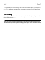
1
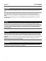
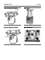
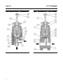
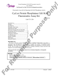
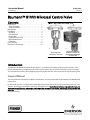
Instruction Manual
81000 Valve
D103366X012
May 2012
Baumann™ 81000 Mikroseal Control Valve
Contents
Figure 1. Baumann 81000 Control Valve
Introduction . . . . . . . . . . . . . . . . . . . . . . . . . . . . . . . . . . . 1
Scope of Manual . . . . . . . . . . . . . . . . . . . . . . . . . . . . . 1
Safety Precautions . . . . . . . . . . . . . . . . . . . . . . . . . . . 2
Maintenance . . . . . . . . . . . . . . . . . . . . . . . . . . . . . . . . . 3
Installation . . . . . . . . . . . . . . . . . . . . . . . . . . . . . . . . . . 3
Air Piping . . . . . . . . . . . . . . . . . . . . . . . . . . . . . . . . . . . 4
Flow Direction . . . . . . . . . . . . . . . . . . . . . . . . . . . . . . 4
Disassembly . . . . . . . . . . . . . . . . . . . . . . . . . . . . . . . . 4
Lapping the Valve Seat . . . . . . . . . . . . . . . . . . . . . . . 5
Bonnet Maintenance . . . . . . . . . . . . . . . . . . . . . . . . . 5
Calibration . . . . . . . . . . . . . . . . . . . . . . . . . . . . . . . . . 5
Parts Ordering . . . . . . . . . . . . . . . . . . . . . . . . . . . . . . . . 6
Dimensions and Weights . . . . . . . . . . . . . . . . . . . . . . 10
W9846
NPS 1/4 Angle Valve
with Baumann 16 Actuator
W9847
NPS 1/2 Inline Valve with
Baumann 16 Actuator, and
FIELDVUEt DVC2000 Digital
Valve Controller
Introduction
The Baumann 81000 Mikroseal control valve (figure 1) is excellent for throttling of liquid or gaseous media. A low
friction mechanical force-amplifying mechanism is used to reduce the travel of the pneumatic or electric actuators.
This mechanism moves the closure diaphragm precisely against the valve orifice to throttle or stop the passing fluid.
Scope of Manual
This instruction manual includes installation, maintenance, and parts information for the Baumann 81000 Mikroseal
control valve.
Do not install, operate, or maintain Baumann 81000 control valves without being fully trained and qualified in valve,
actuator, and accessory installation, operation, and maintenance. To avoid personal injury or property damage, it is
important to carefully read, understand, and follow all the contents of this manual, including all safety cautions and
warnings. If you have any questions about these instructions, contact your Emerson Process Management sales office
before proceeding.
www.Fisher.com
81000 Valve
May 2012
Instruction Manual
D103366X012
WARNING
Always wear protective gloves, clothing and eyewear when performing any installation operations to avoid personal
injury.
Personal injury or property damage caused by sudden release of pressure or bursting of pressure retaining parts may result
if service conditions exceed those for which the product was intended. To avoid injury or damage, provide a relief valve for
over pressure protection as required by government or accepted industry codes and good engineering practices.
Check with your process or safety engineer for any additional measures that must be taken to protect against process
media.
If installing into an existing application, also refer to the WARNING at the beginning of the Maintenance section in this
instruction manual.
CAUTION
This valve is intended for a specific range of pressures, temperatures and other application specifications. Applying
different pressures and temperatures to the valve could result in parts damage, malfunction of the control valve or loss of
control of the process. Do not expose this product to service conditions or variables other than those for which the product
was intended. If you are not sure what these conditions are you should contact your Emerson Process Management sales
office for more complete specifications. Provide the product serial numbers (shown on the nameplate) and all other
pertinent information.
WARNING
If you move or work on an actuator installed on a valve with loading pressure applied, keep your hands and tools away
from the stem travel path to avoid personal injury. Be especially careful when removing the stem connector to release all
loading on the actuator stem whether it be from air pressure on the diaphragm or compression in the actuator springs.
Likewise take similar care when adjusting or removing any optional travel stop. Refer to the relevant actuator Maintenance
Instructions.
If hoisting the valve, take care to prevent people from being injured in case the hoist or rigging slips. Be sure to use
adequate sized hoists and chains or slings to handle the valve.
WARNING
Personal injury could result from packing leakage. Valve packing is tightened before shipment; however, the packing
might require some readjustment to meet specific service conditions.
2
Instruction Manual
81000 Valve
D103366X012
May 2012
Maintenance
WARNING
Avoid personal injury and property damage from sudden release of process pressure or bursting of parts. Before
performing any maintenance operations:
D Do not remove the actuator from the valve while the valve is still pressurized.
D Always wear protective gloves, clothing, and eyewear when performing any maintenance operations.
D Disconnect any operating lines providing air pressure, electric power, or a control signal to the actuator. Be sure the
actuator cannot suddenly open or close the valve.
D Use bypass valves or completely shut off the process to isolate the valve from process pressure. Relieve process pressure
on both sides of the valve. Drain the process media from both sides of the valve.
D Depending on the actuator construction, it will be necessary to manage the pneumatic actuator spring
pre-compression. It is essential to refer to the relevant actuator instructions in this manual to perform safe removal of
the actuator from the valve.
D Use lock-out procedures to be sure the above measures stay in effect while you work on the equipment.
D The valve packing box may contain process fluids that are pressurized, even when the valve has been removed from the
pipeline. Process fluids may spray out under pressure when removing the packing hardware or packing rings, or when
loosening the packing box pipe plug.
D Check with your process or safety engineer for any additional measures that must be taken to protect against process
media.
Note
Whenever a gasket seal is disturbed by removing or shifting gasketed parts, install a new gasket during reassembly. This provides a
good gasket seal because the used gasket may not seal properly.
WARNING
Avoid personal injury or property damage by thoroughly cleaning the line of all dirt, welding chips, scale, oil or grease, and
other foreign material. Failure to do so could result in parts damage, malfunction of the control valve or loss of control of
the process.
Installation
1. Before installing the valve in the pipeline, thoroughly clean the line of all dirt, welding chips, scale, oil or grease, and
other foreign material. A micron size filter is recommended upstream of the valve.
2. Install the valve so that the controlled fluid will flow through the valve body in the direction selected from the
guidelines shown below.
3. A three-valve bypass must be used to permit removal of the control valve from the line without shutting down the
system.
3
81000 Valve
May 2012
Instruction Manual
D103366X012
4. A pressure gauge may be installed in the 1/8 inch port in the bolted bonnet (see figure 4). This gauge tells when
leakage or breakage of the diaphragm has occurred.
WARNING
To avoid personal injury or property damage, do not attempt to do any work on a valve while the system is in operation,
the valve must be isolated 100% from the active system and the isolated line voided of pressure and/or hazardous fluids.
Air Piping
1. For an air-to-extend actuator (air-to-close action), connect the actuating air pressure line to the 1/4 NPT opening in
the upper diaphragm case. For an air-to-retract actuator (air-to-open action) connect the actuating air pressure line
to the 1/4 NPT in the lower diaphragm case. See figures 2 and 3.
2. Use 6.4 mm (1/4 inch) O.D. tubing or equivalent for all air lines. If the air line exceeds 8 m (25 ft) in length, 9.5 mm
(3/8 inch) tubing is preferred. Air pressure should not to exceed 2.5 bar (35 psig).
Flow Direction
There are two possible ways to pass fluid through the valve (see figures 6 and 7). In the flow-to-open mode, fluid
enters from Port A to Port B. In the flow-to-close mode, fluid enters from Port B to Port A.
Each flow direction has its advantages and disadvantages. The following guide will make a selection easier.
Use Flow From Port B to A
D In vacuum applications with spring P/N 81168Z, vacuum on down stream.
D With fluids that have a tendency to cavitate.
D In applications where inlet pressure is low and no seat spring can be tolerated.
D When self-cleaning operation is required for removal of solid particles in flow stream.
Use Flow From Port A to B
D When valve has to fail close in case of bursting or damage to the sealing diaphragm.
Disassembly
WARNING
If there is evidence of process fluid under pressure leaking from the joint, retighten the valve body/joint nuts and return to
the Warning at the beginning of the Maintenance section to provide proper steps have been taken to isolate the valve and
relieve process pressure.
1. Remove the actuator by unscrewing the yoke drive nut (key 9) and lifting off the complete actuator assembly. This
keeps the actuator assembly intact and calibrated to the factory setting. Refer to actuator instructions.
4
Instruction Manual
81000 Valve
D103366X012
May 2012
2. Remove the bolts (key 13) and lift the bonnet yoke assembly (key 2) with the diaphragm (key 5) and O-ring (key 15)
from the valve body (key 1). Lift out the spring (key 6).
3. Remove the O-ring (key 15) and diaphragm (key 5). Wipe with a clean soft cloth and examine for wear.
4. Inspect the valve body sealing surfaces. Refer to the Lapping the Valve Seat procedure in this instruction manual.
Lapping the Valve Seat
If valve seat leakage becomes excessive, it may be necessary to lap the valve seat.
1. Use a good quality lapping compound with a mixture that contains 280 to 600 grit. Apply at several spots around
the plug seating surface (refer to figure 5).
2. Thoroughly lap the valve body on a flat, preferably cast iron, surface plate.
3. Clean the seats thoroughly after lapping.
4. Inspect the diaphragm (key 5) and replace if necessary.
Bonnet Maintenance
1. Remove the actuator by unscrewing the yoke drive nut (key 9) and lifting off the complete actuator assembly. Hold
the flattened portions of the bonnet yoke (key 2) in a vise and unscrew the valve bonnet (key 8) using a 2-1/4 inch
wrench. Remove and inspect the bearing cartridge assembly (key 4) and O-ring (key 49).
2. Reinsert the parts, O-ring (key 49) and bearing cartridge assembly (key 4), ensuring the bearings extend below the
side plate of the bearing cartridge assembly (key 4) and contact the piston subassembly (key 3). With the plunger
(key 10) removed, screw the bonnet (key 8) onto the yoke (key 2). There should be no binding or galling. Tighten
the bonnet with a wrench until there is metal-to-metal contact.
3. Insert the plunger (key 10) and push it in and out. The piston subassembly (key 3) should travel easily up and down.
Calibration
1. Reassemble the valve by inserting the spring (key 6), O-ring (key 15), and diaphragm (key 5) into the valve body.
2. Replace the bonnet yoke assembly (key 2) and install the bolts (key 13) and tighten. Add the jam nut (key 27) and
travel indicator disk (key 58) to the plunger (key 10). Line up the plunger (key 10) in the bearing cartridge assembly
(key 4). Screw the actuator onto the plunger (key 10) until the actuator yoke touches the bonnet (key 8). Lock the
actuator with the drive nut (key 9).
3. To prevent damage to the plunger (key 10) or the bearing cartridge subassembly (key 4), be sure the hex jam nut
(key 27) is not tightened against the travel indicator (key 58).
CAUTION
To prevent damage to the plunger (key 10) or bearing cartridge subassembly (key 4), be sure the hex jam nut (key 27) is not
tightened against the travel indicator (key 58).
Do Not Attempt to Rotate the Plunger (key 10)
1. For an air-to-retract actuator (air-to-open). Apply 6.9 bar (100 psi) air pressure (or N2) to the normal valve inlet.
Apply 0.2 bar (3.2 psi) air signal to the actuator. Use 0.07 bar (1 psi) signal to the actuator if the inlet pressure
exceeds 6.9 bar (100 psi). If the valve leaks, slowly turn the actuator stem counterclockwise. This will move the
plunger (key 10) down until leakage is below 1 cc/min. Lock the plunger (key 10) in position with the jam nut (key
5
81000 Valve
May 2012
Instruction Manual
D103366X012
27). Calibrate the travel scale and check for 12.7 mm (1/2 inch) valve travel; apply a 1.04 bar (15 psi) signal. Reverse
the signal; the plunger should move in the opposite direction with less than 0.014 bar (0.2 psi) signal change.
2. For an air-to-extend actuator (air-to-close), use the same procedure as in step one, except apply 0.88 bar (12.8 psi)
to the actuator to calibrate the shut off position.
Parts Ordering
When corresponding with your Emerson Process Management sales office about this equipment, always mention the
valve serial number. When ordering replacement parts, also specify the key number, part name, and desired material
using the following parts tables.
WARNING
Use only genuine Fisherr replacement parts. Components that are not supplied by Emerson Process Management should
not, under any circumstances, be used in any Fisher valve, because they may void your warranty, might adversely affect the
performance of the valve, and could cause personal injury and property damage.
6
Instruction Manual
81000 Valve
D103366X012
May 2012
Figure 2. Air-to-Extend (Air-to-Close Action)
Figure 4. 1/8 Port
1/4 NPT OPENING
E1369
W9916
Figure 3. Air-to-Retract (Air-to-Open Action)
Figure 5. Seating Surfaces
1/4 NPT OPENING
E1234
W9917
7
Instruction Manual
81000 Valve
May 2012
Figure 6. Baumann 81000 NPS 1/4 Angle Valve Body
E1324
8
D103366X012
Figure 7. Baumann 81000 NPS 1/2 Inline Valve Body
E1325
Instruction Manual
81000 Valve
D103366X012
May 2012
Table 1. Common Parts
Key Number
Quantity
Description
Part Number
1
1
Valve Body
Refer to table 2
2
1
Bonnet Yoke, NPS 1/2
81306
Bonnet Yoke, NPS 1/4
81302
Piston Subassembly, NPS 1/2
81188
3
1
4*
1
5*
1
Piston Subassembly, NPS 1/4
81170
Bearing Cartridge Subassembly
81180-2
Closure Diaphragm, NPS 1/2, 316 Stainless Steel
81145
Closure Diaphragm, NPS 1/2, N10276 Nickel Alloy
81145-1
Closure Diaphragm, NPS 1/4, 316 Stainless Steel
37141
Closure Diaphragm, NPS 1/4, N10276 Nickel Alloy
37141-1
6*
1
Seat Spring
81168Z
7*
1
Wave Spring
81401
8
1
Bonnet
81205
9
1
Drive Nut, (Yoke)
011757-003-153
10*
1
13
4
14*
1
Plunger
Refer to table 2
NPS 1/2, Allen head Bolt 3/8-16x2-5/8
81195S
NPS 1/4, Allen head Bolt M8x30
81197S
O-Ring, Plunger
81147
O-Ring, NPS 1/2 Body (PTFE)
81165-1
15*
1
O-Ring, NPS 1/4 Body, (PTFE)
37186-1
27
1
Jam Nut
81841
49*
1
O-Ring
81206
58
1
Travel Indicator Disk
011765-002-152
Table 2. Baumann 81000 Valve Body and Plunger
PLUG TRAVEL
ORIFICE DIAMETER
DIAPHRAGM TRAVEL
81000 VALVE BODY(1)
(KEY 1)
PLUNGER
(KEY 10)
Cv
Kv
mm
Inch
mm
Inch
NPS 1/2
NPS 1/4
Baumann
16 Actuator
Baumann
32 Actuator
0.01
0.009
0.635
0.025
0.1778
0.007
81504(2)
81558(2)
81193 (5_)
81933 (5_)
0.03
0.026
1.60
0.063
0.1778
0.007
81503(2)
81557(2)
81193 (5_)
81933 (5_)
0.10
0.09
7.92
0.312
0.1778
0.007
81501(2)
81555(2)
81193 (5_)
81933 (5_)
0.30
0.26
7.92
0.312
0.3810
0.015
81501(2)
81555(2)
81192 (13_)
81931 (13_)
0.50
0.43
13.2
0.520
0.0005
0.012
81507(2)
N/A
81191 (8_)
81934 (8_)
0.70
0.60
13.2
0.520
0.3810
0.015
81507(2)
N/A
81192 (13_)
81931 (13_)
1. Add the suffix of the letter "H" to the valve body part number when N10276 Nickel Alloy material is specified.
2. Refer to key 5 in table 1 for the appropriate closure diaphragm.
9
Instruction Manual
81000 Valve
May 2012
D103366X012
Figure 8. 81000 Angle Valve with Baumann 16
Actuator and FIELDVUE DVC6000 Digital Valve
Controller
Figure 10. Baumann 16 Actuator with FIELDVUE
DVC6000 Digital Valve Controller, Top View
159
(46.25)
R235
(R9.24)
145
(5.75)
1/4 NPT
123
(4.86)
81
(3.17)
24 (0.94)
54
212
(8.35)
1/4 NPT
mm
(inch)
(42.13)
NOTE: BAUMANN 16 ACTUATOR REQUIRES
77mm (3 Inches) VERTICAL CLEARANCE
mm
(inch)
E1329
E1326
Figure 9. 81000 Inline Valve with Baumann 16
Actuator and FIELDVUE DVC6000 Digital Valve
Controller
Figure 11. Baumann 16 Actuator with Fisher
3660/3661 and 67CFR Airset
159
(46.25)
129 (5.1)
212
(8.35)
159
(46.25)
93 (3.7)
125
(4.9)
39
(1.6)
146
(5.75)
1/4 NPT
146
(5.76)
108
(4.25)
67CFR
35
(1.36)
1/2 NPT
E1327
10
62
(2.45)
3660/3661
POSITIONER
NOTE: BAUMANN 16 ACTUATOR REQUIRES
77mm (3 Inches) VERTICAL CLEARANCE
mm
(inch)
E1331
mm
(inch)
Instruction Manual
81000 Valve
D103366X012
May 2012
Figure 12. Baumann 16 Actuator with FIELDVUE
DVC2000 Digital Valve Controller
Figure 13. Baumann 16 Actuator with FIELDVUE
DVC2000 Digital Valve Controller, Top View
159 (6.3)
83 (3.3)
127
(5.01)
175
(6.9)
mm
(inch)
NOTE: BAUMANN 16 ACTUATOR REQUIRES
77mm (3 Inches) VERTICAL CLEARANCE
E1330
E1328
Table 3. Baumann 81000 Valve Weights
mm
(inch)
166 (6.52)
166 (6.52)
NOTE: BAUMANN 16 ACTUATOR REQUIRES
77mm (3 Inches) VERTICAL CLEARANCE
Table 4. Baumann Actuator Weights
6.35 mm (NPS 1/4)
12.7 mm (NPS 1/2)
kg
lbs
kg
lbs
BAUMANN
ACTUATOR
kg
lbs
1.35
3
1.82
4
16
2.1
4.6
WEIGHT
11
81000 Valve
May 2012
Instruction Manual
D103366X012
Neither Emerson, Emerson Process Management, nor any of their affiliated entities assumes responsibility for the selection, use or maintenance
of any product. Responsibility for proper selection, use, and maintenance of any product remains solely with the purchaser and end user.
Baumann, Fisher, and FIELDVUE are marks owned by one of the companies in the Emerson Process Management business unit of Emerson Electric Co.
Emerson Process Management, Emerson, and the Emerson logo are trademarks and service marks of Emerson Electric Co. All other marks are the property
of their respective owners.
The contents of this publication are presented for informational purposes only, and while every effort has been made to ensure their accuracy, they are not
to be construed as warranties or guarantees, express or implied, regarding the products or services described herein or their use or applicability. All sales are
governed by our terms and conditions, which are available upon request. We reserve the right to modify or improve the designs or specifications of such
products at any time without notice.
Emerson Process Management
Marshalltown, Iowa 50158 USA
Sorocaba, 18087 Brazil
Chatham, Kent ME4 4QZ UK
Dubai, United Arab Emirates
Singapore 128461 Singapore
www.Fisher.com
12
E 2009, 2012 Fisher Controls International LLC. All rights reserved.