1
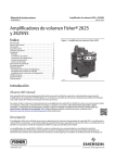
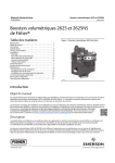
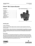
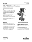
Product Bulletin
2625 Volume Booster
62.3:2625
January 2015
D200071X012
Fisherr 2625 and 2625NS Volume Boosters
A Fisher 2625 or 2625NS volume booster is used in
conjunction with a positioner on a throttling control
valve to increase stroking speed. The 2625NS is a
nuclear‐service version and uses elastomeric
components that better withstand high temperature
and radiation environments.
The booster incorporates fixed deadband, soft seat
construction, and an integral bypass restriction to
eliminate positioner saturation problems that can
occur with volume boosters that do not have these
features. Adjustment of the integral bypass restriction
is necessary for system stability. This adjustment does
not affect the deadband of the volume booster, but
does permit the control valve to respond to small input
signal changes without sacrificing steady‐state
accuracy. It also allows the booster to deliver
high‐volume output for fast stroking when large, rapid
input signal changes occur.
The volume booster is used to improve stroking speed.
If precision valve control is required, the use of a
positioner is recommended. If the volume booster is to
be used only with an actuator, for on‐off control, the
integral bypass restriction on the booster must be
closed (turned fully clockwise).
W4727-1
Features
n Fast Response—Booster delivers the volume needed
for rapid actuator stroking when large input
changes suddenly occur.
n Adjustable Response—Integral bypass restriction
Connectors and piping can be installed with either
2625 or 2625NS volume booster for diagnostic
testing.
tunes the booster response so that smooth actuator
motion follows the slow signal changes.
n Efficient Operation—Soft seats provide tight shutoff
to reduce unnecessary air consumption and
eliminate saturation of positioner relays.
The 2625 is certified for use in Safety Instrumented
System (SIS) applications. Certification is by exida
Consulting LLC, a global provider of functional safety
and control system security. SIS certification is
identified on the product by the EXIDA logo on the
2625 nameplate.
www.Fisher.com
n Maintains Accuracy—Booster permits high actuator
stroking speeds upon demand without degrading
the positioner steady‐state accuracy.
n SIL 3 Capable - Certified for use in Safety
Instrumented System (SIS) applications.
Product Bulletin
2625 Volume Booster
62.3:2625
January 2015
D200071X012
Specifications
Supply Pressure Ranges
When used in conjunction with a positioner or other
pneumatic accessory, always pipe the positioner and
volume booster with one common supply through a
Fisher 67D, 67DR, or 95H regulator (see figure 2). A
high‐capacity filter, such as the Fisher 262K, should
be installed in the supply line to the regulator. Supply
pressure also must not exceed the maximum
pressure rating of the actuator. Constructions are
available in two maximum supply ranges.
When Normally Used With Diaphragm Actuators: Up
to 2.8 bar (40 psig)
When Normally Used With Piston Actuators: Up to
10.3 bar (150 psig)
Input Signal Pressure
Positioner output
Maximum Input Signal Pressure
10.3 bar (150 psig)
Fixed Input‐to‐Output Pressure Ratio
1 to 1
Nominal Deadband
Percent of Positioner Output Span(1):
2.4 mm (0.094 inch) exhaust port: 2%
9.5 mm (0.375 inch) exhaust port: 3.5%
12.7 mm (0.5 inch) exhaust port: 5%
Upper and Lower Valves:
2625: Nitrile‐CSM rubber/aluminum/stainless steel
2625NS: EPDM/aluminum/stainless steel
O‐Rings:
2625: Nitrile
2625NS: EPDM
Connectors for Diagnostic Testing: J Stainless steel
or J brass
Operative Temperature Limits(2)
2625: -40 to 71_C (-40 to 160_F)
2625NS: -40 to 93_C (-40 to 200_F)
Connections
Input Signal: 1/4 NPT
Supply and Output: 3/4 NPT
Port Diameters(3)
Supply Port: J9.5 mm (0.375 inch) or
J 12.7 mm (0.5 inch)
Exhaust Port: J2.4 mm (0.094 inch),
J9.5 mm (0.375 inch) or J12.7 mm (0.5 inch)
Maximum Flow Coefficients
See table 1
Hazardous Area Classification
Complies with the requirements of ATEX Group II
Category 2 Gas and Dust
Construction Materials
Body: Aluminum
Seat Ring: Brass
Safety Instrumented System Classification
SIL3 capable - certified by exida Consulting LLC
Diaphragms
2625: Nitrile/nylon
2625NS: EPDM/meta‐aramid
Approximate Weight
2.3 kg (5 lb)
NOTE: Specialized instrument terms are defined in ANSI/ISA Standard 51.1 - Process Instrument Terminology.
1. Zero to maximum supply.
2. The pressure/temperature limits in this document and any applicable code or standard should not be exceeded.
3. May be used in any combination.
2
Product Bulletin
2625 Volume Booster
62.3:2625
January 2015
D200071X012
Figure 1. Sectional View of Fisher 2625 Volume Booster
INPUT SIGNAL
BYPASS RESTRICTION
ADJUSTING SCREW
DIAPHRAGMS
EXHAUST
PORT
BYPASS
RESTRICTION
EXHAUST
SUPPLY
PORT
OUTPUT TO
ACTUATOR
SUPPLY
W0679‐1
Principle of Operation
Refer to figures 1 and 2. Because of the bypass
restriction, large input signal changes register on the
booster input diaphragm sooner than in the actuator.
A large, sudden change in input signal causes a
pressure differential to exist between the input signal
and the output of the booster. When this occurs, he
diaphragms move to open either the supply port or the
exhaust port, whichever action is required to reduce
the differential. The port remains open until the
difference between the booster input and output
pressures returns to within the deadband limit of the
booster. With the bypass restriction adjusted for stable
operation, a signal with small magnitude and rate
changes passes through the bypass restriction and into
the actuator without initiating booster operation.
Both supply and exhaust ports remain closed,
preventing unnecessary air consumption and possible
saturation of positioner relays.
3
Product Bulletin
2625 Volume Booster
62.3:2625
January 2015
D200071X012
Figure 2. Typical Installations
2625
VOLUME
BOOSTER
2625
VOLUME
BOOSTER
SUPPLY
OUTPUT A
SIGNAL
OUTPUT B
2625
VOLUME
BOOSTER
DIGITAL VALVE CONTROLLER
ACTUATOR
67D, 67DR
OR 95H
POSITIONER
OUTPUT
E1407
SIGNAL
WITH A PISTON ACTUATOR
POSITIONER
SUPPLY
ACTUATOR
67D, 67DR
OR 95H
A0794‐3
WITH A DIAPHRAGM ACTUATOR
Note:
1 Connection location for diagnostic testing
Table 1. Maximum Flow Coefficients(1)
PORT SIZE COMBINATIONS
Supply Port
mm
COEFFICIENTS
Exhaust Port
Supply Port
Exhaust Port
Inch
mm
Inch
Cv
Cv
9.5
3/8
2.4
9.5
12.7
3/32
3/8
1/2
3.74
3.74
3.74
0.23
2.29
3.40
12.7
1/2
2.4
9.5
12.7
3/32
3/8
1/2
4.98
4.98
4.98
0.24
2.30
3.40
0.37
0.31
FIELDVUE DVC2000 digital valve controller
Low Pressure Relay
High Pressure Relay
Fisher 3570 valve positioner
0.13
0.19
0.25
0.15
0.20
0.25
Fisher 3582 valve positioner
0.17
0.19
Fisher 3610J, 3610JP, 3611JP, 3620J, 3620JP, 3621JP valve positioners
0.37
0.30
FIELDVUEt DVC6200, DVC6200 SIS, DVC6200f, DVC6200p, DVC6000, DVC6000 SIS, DVC6000f
digital valve controllers
1. Consult your Emerson Process Management sales office for special stroking speed requirements.
4
Product Bulletin
2625 Volume Booster
62.3:2625
January 2015
D200071X012
Figure 3. Dimensions
1/4‐18 NPT INPUT CONN
21
(0.84)
111
(4.38)
9 EXHAUST
HOLES 7 (0.28) DIA
3/4‐14 NPT
SUPPLY CONN
48
(1.88)
60
(2.38)
3/4‐14 NPT
OUTPUT TO ACTUATOR
121
(4.75)
A0807‐3
mm
(INCH)
2625NS for Nuclear
Service Applications
The 2625NS volume booster uses EPDM
(ethylene‐propylene) elastomeric parts. These parts
have superior resistance to degradation at elevated
temperature and radiation levels. This version is
designed for nuclear service applications where oil‐free
supply air is available.
Both the 2625 and 2625NS are available as
safety‐related items when processed using the
commercial grade dedication section of the 10CFR50,
Appendix B, quality assurance program. 10CFR21
reporting is also part of the safety related processing
program. Seismic operability testing has been done to
qualify both versions as rigid items at levels up to 9g's
uniaxial (in each axis). Further nuclear service
qualification data is available on request.
5
Product Bulletin
2625 Volume Booster
62.3:2625
January 2015
Installation
Figure 2 shows typical installations for the 2625 or
2625NS volume booster on piston and diaphragm
actuators. A single regulator that supplies both the
positioner and booster (or boosters) is recommended.
The supply medium must be clean, dry, oil‐free air or
non‐corrosive gas.
D200071X012
Ordering Information
When ordering, specify:
1. Supply and exhaust port sizes. See table 1 for Cv
values.
2. Supply pressure range of up to 2.8 bar (40 psig) or
up to 10.3 bar (150 psig).
Note
3. Stroking speed information when being mounted at
the factory, for proper tuning of the instruments.
Specify either critical or non‐critical stroke speed
time.
Use a clean, dry, oil‐free air supply with instruments
containing EPDM components. EPDM is subject to
degradation when exposed to petroleum‐base lubricants.
Note
Critical stroke speed time example: Valve to stroke in both
directions in 4 seconds or less.
Non‐critical stroke speed time example: Valve to stroke in
approximately 4 seconds in both directions.
Keep in mind that many actuators require larger casing
or cylinder connections to take full advantage of the
booster's ability to deliver its high‐volume output.
Dimensions are shown in figure 3. Ensure that the
supply pressure is connected to correspond with the
flow arrow on the booster.
6
4. Nuclear service, if applicable. Consult your Emerson
Process Management sales office for ordering
assistance.
2625 Volume Booster
D200071X012
Product Bulletin
62.3:2625
January 2015
7
Product Bulletin
62.3:2625
January 2015
2625 Volume Booster
D200071X012
Neither Emerson, Emerson Process Management, nor any of their affiliated entities assumes responsibility for the selection, use or maintenance
of any product. Responsibility for proper selection, use, and maintenance of any product remains solely with the purchaser and end user.
Fisher and FIELDVUE are marks owned by one of the companies in the Emerson Process Management business unit of Emerson Electric Co. Emerson Process
Management, Emerson, and the Emerson logo are trademarks and service marks of Emerson Electric Co. All other marks are the property of their respective
owners.
The contents of this publication are presented for informational purposes only, and while every effort has been made to ensure their accuracy, they are not
to be construed as warranties or guarantees, express or implied, regarding the products or services described herein or their use or applicability. All sales are
governed by our terms and conditions, which are available upon request. We reserve the right to modify or improve the designs or specifications of such
products at any time without notice.
Emerson Process Management
Marshalltown, Iowa 50158 USA
Sorocaba, 18087 Brazil
Chatham, Kent ME4 4QZ UK
Dubai, United Arab Emirates
Singapore 128461 Singapore
www.Fisher.com
E
8 1986, 2015 Fisher Controls International LLC. All rights reserved.