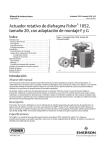
1
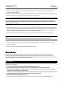
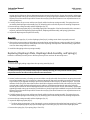
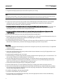
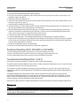
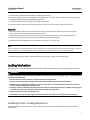
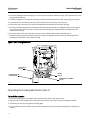
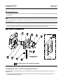
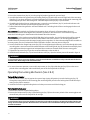
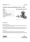
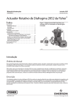
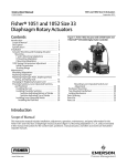
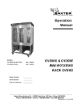
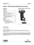
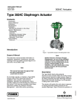
Instruction Manual 2052 Actuator D103296X012 November 2011 Fisherr 2052 Diaphragm Rotary Actuator Contents Introduction . . . . . . . . . . . . . . . . . . . . . . . . . . . . . . . . . 1 Scope of Manual . . . . . . . . . . . . . . . . . . . . . . . . . . . . . 1 Description . . . . . . . . . . . . . . . . . . . . . . . . . . . . . . . . . 1 Specifications . . . . . . . . . . . . . . . . . . . . . . . . . . . . . . . 3 Installation . . . . . . . . . . . . . . . . . . . . . . . . . . . . . . . . . . 4 Actuator Mounting . . . . . . . . . . . . . . . . . . . . . . . . . . 5 Maintenance . . . . . . . . . . . . . . . . . . . . . . . . . . . . . . . . . 7 Replacing Diaphragm . . . . . . . . . . . . . . . . . . . . . . . . 8 Replacing Diaphragm Plate, Diaphragm Rod Assembly, and Spring(s) . . . . . . 9 Changing Or Replacing Actuator Lever . . . . . . . . . 11 Positioner Mounting (3610 or DVC6020) . . . . . . . 12 Top-Mounted Handwheel . . . . . . . . . . . . . . . . . . . . 12 Locking Mechanism . . . . . . . . . . . . . . . . . . . . . . . . . 13 Parts Ordering . . . . . . . . . . . . . . . . . . . . . . . . . . . . . . . 17 Parts List . . . . . . . . . . . . . . . . . . . . . . . . . . . . . . . . . . . 17 Figure 1. Fisher Control-Disk™ Valve with 2052 Actuator and DVC6200 Digital Valve Controller W9425-2 Introduction Scope of Manual This instruction manual includes installation, adjustment, operation, maintenance, and parts information for the Fisher 2052 diaphragm rotary actuator (figure 1). Instructions for the control valve, positioner, manual actuator, and other accessories are included in separate manuals. Do not install, operate, or maintain a 2052 actuator without being fully trained and qualified in valve, actuator, and accessory installation, operation and maintenance. To avoid personal injury or property damage, it is important to carefully read, understand, and follow all the contents of this manual, including all safety cautions and warnings. If you have any questions about these instructions, contact your Emerson Process Management sales office before proceeding. Description 2052 spring-and-diaphragm rotary actuators are used on rotary-shaft valve bodies for throttling or on-off applications. The 2052 may be used for on-off service without a positioner, or it may be used for throttling service with a positioner, depending on service conditions. The 2052 has an ISO 5211 mating interface that allows installation to non-Fisher valves. Refer to separate bulletins for valve and positioner information. www.Fisher.com Instruction Manual 2052 Actuator November 2011 D103296X012 A top-mounted handwheel option is available for infrequent service as a manual actuator. For repeated or daily manual operation, the unit should be equipped with a side-mounted declutchable 1078 manual actuator. Externally adjustable travel stops are used to limit the degree of rotation at both ends of the actuator stroke. The lever for the 2052 actuator is supported by bushings. The lever may be changed to accommodate valve bodies with different size valve shafts. Table 1. Fisher 2052 Actuator Specifications Specifications Actuator Mounting Connections Splined shaft connection, ISO 5211 actuator-to-bracket connection Size 1: F07, Size 2: F10, Size 3: F14 Actuator Sizes See table 2 Operating Pressure(1) See table 3 Maximum Diaphragm Casing Pressure Size 1, 2, and 3 Actuators: 5 barg (73 psig) Pressure Connection See table 4 Torque Output See table 3 Actuator Temperature Capabilities(1) -45 to 80_C (-50 to 176_F) Operation Field reversible between PDTC and PDTO; right- and left-hand mounting, any angle of orientation Controller/Positioners Available Size 1: 22.2 kg (49 lb) Size 2: 54.4 kg (120 lb) Size 3: 113 kg (250 lb) DVC2000, DVC6020, DVC6030, DVC6200, 3610J, 3620J, 4190, C1 Accessories Available 846, 646, 2625, and 67C Series, switches, i2P-100, VBL, DXP, GO™ Handwheel Top-mounted handwheel: Optional on Size 1 and 2 actuators only Declutchable handwheel: Optional on Size 1, 2, and 3 actuators Operational Lockout Available for customer-supplied padlock to lock the actuator in the spring-fail position Approximate Weight 1. The pressure/temperature limits in this manual should not be exceeded. Table 2. Actuator and Shaft Size Availability SHAFT SIZE Table 3. Torque versus Actuator Size OPERATING PRESSURE ACTUATOR SIZE Inches 1 2 3 1/2 available not available not available 5/8 available available not available 3/4 available available 2 barg (29 psig)(1) 4 barg (58 psig)(2) Torque Torque NSm lbfSin NSm available 1 (PDTO, PDTC) 25.5 226 51.2 lbfSin 453 105 930 210 1860 1 not available available available 2 (PDTO, PDTC) 1-1/4 not available available available 3 (PDTO) 327 2890 631 5583 1-1/2 not available not available available 3 (PDTC) 280 2479 584 5173 1-3/4 not available not available available 2 not available not available available Table 4. Pressure Connections ACTUATOR SIZE 2 ACTUATOR SIZE AND ACTION PRESSURE CONNECTION 1/4 NPT 1/2 NPT 3/4 NPT G 1/4 optional 1 standard optional not available 2 standard optional not available optional 3 not available standard optional not available 1. Operating pressure up to 3 barg (44 psig) is allowable for single spring construc tion. 2. Operating pressure up to 5 barg (73 psig) is allowable for dual spring construction. Instruction Manual 2052 Actuator D103296X012 November 2011 Table 5. Fisher 2052 Actuator Mounting Styles VALVE SERIES OR DESIGN VALVE SERIES OR DESIGN CV500 V500 DISK/BALL ROTATION TO CLOSE A11, 8510B, 8532, 8560, 8580, 9500, and Control-Disk Valve A B A B CW CW B A CCW CCW D C D C CW CW C D CW CW C D NA NA NA NA NA NA MOUNTING ACTION(1) BALL/PLUG ROTATION TO CLOSE V150, V200 & V300 Right-Hand PDTC PDTO CCW CCW Left-Hand PDTC PDTO Left-Hand (Optional)(2) PDTC PDTO 1. PDTC–Push-down-to-close, and PDTO–Push-down-to-open. 2. A left hand mounted ball will be required for the NPS 3 through 12 Vee-Ball Series B and the NPS 14 and 16, with or without attenuator. Figure 2. Fisher 2052 Actuator Mounting Styles LEFT HAND MOUNTING RIGHT HAND MOUNTING VALVE INLET VALVE INLET STYLE D SHOWN STYLE B SHOWN STYLE D STYLE C STYLE A STYLE B POSITION 1 STANDARD 2 4 3 POSITION 1 STANDARD FLOW 4 2 3 2 4 FLOW 3 4 2 3 GE37285-B Specifications Specifications are shown in table 1 for 2052 actuators. Specifications for actuator operation are stamped on a metal nameplate attached to the actuator. 3 Instruction Manual 2052 Actuator November 2011 D103296X012 Table 6. Bolting Torque Requirements(1) DESCRIPTION KEY NUMBER Rod End Bearing Clamping Bolt Torque , Key 16 End Plate to Housing Bolt Torque, Key 4 Diaphragm Plate to Rod Bolt Torque, Key 7 Casing Bolt Torque, Key 8 Housing to Yoke Bolt Torque, Key 28 Lever-Spline Clamping Bolt Torque, Key 15 Optional Lockout Kit Mounting Bolt Torque, Key 53 TORQUE ACTUATOR SIZE NSm LbfSft 1 2 3 1 2 3 1 2 3 1 2 3 1 2 3 1 2 3 1 2 3 38 180 400 68 120 210 27 115 300 55 55 55 27 68 245 38 115 175 NA 88 340 28 130 295 50 90 155 20 85 220 40 40 40 20 50 180 28 85 130 NA 65 250 FASTENER LUBRICATION None None Anti-Seize Lubricant None None None None 1. Exceeding any torque requirements could damage the actuator and impair safe operation. Installation WARNING Always wear protective gloves, clothing, and eyewear when performing any installation operations. Check with your process or safety engineer for any other hazards that may be present from exposure to process media. If installing into an existing application, also refer to the WARNING at the beginning of the Maintenance section in this instruction manual. CAUTION To avoid parts damage, do not apply pressure that exceeds the Maximum Diaphragm Casing Pressure in table 1. Use pressure-limiting or pressure-relieving devices to prevent the Operating Pressure from exceeding the values shown in table 3. The actuator, as it comes from the factory, is normally mounted on a valve body. If the actuator is shipped separately or if it is necessary to mount the actuator on the valve, perform the procedures presented in the Actuator Mounting section. Follow the procedures given in the valve instruction manual when installing the control valve in the pipeline. If a positioner is ordered with the actuator, the pressure connection to the actuator is normally made at the factory. If it is necessary to make this connection, run tubing of the appropriate size for the diaphragm casing pressure connection (reference table 4) between the pressure connection and the instrument. Keep the length of tubing or pipe as short as possible to avoid transmission lag in the control signal. When the control valve is completely installed and connected to the controlling instrument, check to make sure that the action is correct (air-to-open or air-to-close) and that the controlling instrument is properly configured for the 4 Instruction Manual D103296X012 2052 Actuator November 2011 desired action. For successful operation, the diaphragm rod assembly, lever, and valve shaft must move freely in response to changes in the loading pressure on the diaphragm. Actuator Mounting WARNING Avoid personal injury or property damage from sudden release of process pressure or bursting of parts. Before performing any maintenance operations: D Do not remove the actuator from the valve while the valve is still pressurized. D Always wear protective gloves, clothing, and eyewear when performing any maintenance operations. D Disconnect any operating lines providing air pressure, electric power, or a control signal to the actuator. Be sure the actuator cannot suddenly open or close the valve. D Use bypass valves or completely shut off the process to isolate the valve from process pressure. Relieve process pressure from both sides of the valve. Drain the process media from both sides of the valve. D Safely vent the power actuator loading pressure. D Use lock-out procedures to be sure that the above measures stay in effect while you work on the equipment. D The valve packing box may contain process fluids that are pressurized, even when the valve has been removed from the pipeline. Process fluids may spray out under pressure when removing the packing hardware or packing rings. D Check with your process or safety engineer for any hazards that may be present from exposure to process media. Use the following steps to mount the actuator or to change actuator mounting style or position. Unless otherwise specified, key numbers referenced in the following procedures are shown in figure 7 for the 2052 actuator. If the Actuator is mounted on a valve body and it is necessary to change mounting style or position, the actuator must first be separated from the valve body. 1. Isolate the valve body from the process. Release process pressure and vent all actuator pressure. 2. Remove the cover or plug (key 2). WARNING To avoid personal injury and equipment damage from moving parts, keep fingers and tools clear while stroking the actuator with the cover removed. 3. Loosen the cap screw (key 15). 4. Separate the actuator from the valve body by removing the cap screws and nuts which secure the valve to the mounting yoke (key 27). Proceed to step 5. If the actuator is not mounted on a valve body ensure the up and down travel stops (see figure 3) are adjusted correctly to achieve the desired actuator rotation. Use the travel indicator (key 21) and travel scale (key 19) as reference. Note Once each travel stop is properly positioned, adequately tighten the hex nut (key 24) to lock the travel stop in place. 5 Instruction Manual 2052 Actuator November 2011 D103296X012 5. Refer to figure 2 and table 5 for available mounting styles and positions. The actuator is normally positioned vertically with the valve in a horizontal pipeline. 6. Determine whether the actuator mounting yoke (key 27) will be mounted on the end plate assembly (key 3) side or on the actuator housing boss side of the actuator. If the desired mounting position and style require moving the mounting yoke (key 27) and travel indicator components to opposite sides of the actuator, remove the machine screws (keys 20 and 22), the travel indicator scale (key 19), and the travel indicator (key 21). Remove the cap screws (key 28) and the mounting yoke (key 27). Install the mounting yoke in the desired position (on the end plate assembly or on the actuator housing boss). Tighten the mounting cap screws to the torque specified in table 6. Install the travel indicator components on the opposite side of the actuator. WARNING To avoid personal injury or property damage, ensure the travel indicator is installed correctly to coincide with the desired actuator action. Refer to figure 3 for more information. Figure 3. Fisher 2052 Actuator Travel Stops and Travel Indication INDICATOR ORIENTATION FOR PDTO TRAVEL INDICATOR SCALE INDICATOR ORIENTATION FOR PDTC VIEW A KEY 22 DOWN TRAVEL STOP UP TRAVEL STOP KEY 20 TRAVEL INDICATOR VIEW A 7. Before sliding the valve shaft into the lever, position the valve ball or disk as follows: For push-down-to-close action, the valve ball or disk should be in the fully open position. For push-down-to-open action, the valve ball or disk should be in the fully closed position (see the valve body instruction manual). 8. Make sure that the index markings on the valve shaft are properly aligned with either the markings on the lever or the travel indicator scale mounting holes. Slide the valve shaft into the lever. (See figure 4 for one possible orientation.) Install the valve mounting cap screws and nuts. Tighten to the torque value given in the appropriate valve body instruction manual. 6 Instruction Manual D103296X012 2052 Actuator November 2011 9. Ensure all end play in the valve shaft is removed by directing the valve shaft and control element toward the actuator as much as possible. 10. Tighten the socket head cap screw (key 15) which compresses the splined lever connection to the valve shaft (see table 6). Install the cover or plug (key 2) into the access hole in the housing. CAUTION When adjusting the travel stop for the closed position of the valve ball or disk, refer to the appropriate valve instruction manual for detailed procedures. Undertravel or overtravel at the closed position may result in poor valve performance and/or damage to the equipment. 11. Adjust the up travel stop (see figure 3) so that the valve ball or disk is in the desired position. When adjusting the up travel stop, ensure the stop is not backed out too far, causing the lever to over-rotate. Over-rotation of the lever may cause damage to valve components. Avoid over-rotation by adjusting the up travel stop so that the travel indicator screws (key 22) align with the travel scale screws (key 20). See figure 3. 12. Stroke the actuator and adjust the down travel stop so that the valve ball or disk is in the desired position. Note Once each travel stop is properly positioned, adequately tighten the hex nut (key 24) to lock the travel stop in place. 13. Make sure that the travel indicator pointer matches the ball or disk position. Remove and install in the proper position if necessary. 14. Refer to the table of contents for accessory installation procedures. Maintenance Actuator parts are subject to normal wear and must be inspected and replaced as necessary. The frequency of inspection and replacement depends upon the severity of service conditions. Instructions are given below for disassembly and assembly of parts. Key numbers referenced in the following steps are shown in figure 7 for the 2052, except as listed below or otherwise specified in the procedures. WARNING Avoid personal injury or property damage from sudden release of process pressure or bursting of parts. Before performing any maintenance operations: D Do not remove the actuator from the valve while the valve is still pressurized. D Always wear protective gloves, clothing, and eyewear when performing any maintenance operations. D Disconnect any operating lines providing air pressure, electric power, or a control signal to the actuator. Be sure the actuator cannot suddenly open or close the valve. D Use bypass valves or completely shut off the process to isolate the valve from process pressure. Relieve process pressure from both sides of the valve. Drain the process media from both sides of the valve. D Safely vent the power actuator loading pressure. D Use lock-out procedures to be sure that the above measures stay in effect while you work on the equipment. 7 Instruction Manual 2052 Actuator November 2011 D103296X012 D Check with your process or safety engineer for any hazards that may be present from exposure to process media. Replacing Diaphragm Isolate the valve body from the process. Release process pressure and vent all actuator pressure. Disassembly 1. Remove the supply tubing or pipe from the top casing assembly (key 5). WARNING To avoid personal injury from precompressed spring force suddenly thrusting parts away from the actuator, spring compression must first be relieved. Closely follow the instructions below. Figure 4. Orientation of the Fisher 2052 Actuator Lever into the Housing and Aligning the Actuator to the Valve Shaft Markings UP TRAVEL STOP 2. Loosen, but do not remove, all casing cap screws and hex nuts (keys 8 and 9). Ensure there is no spring force to the top casing assembly (key 5). If spring force is detected against the top casing assembly, ensure the up travel stop cap screw (key 23) is adjusted correctly to prevent over-rotation of the lever (key 14). Refer to figure 3. The travel indicator screws (key 22) in the end of the lever should be in alignment with the travel scale screws (key 20). If the up travel stop is confirmed to be adjusted correctly and force is still detected against the top casing assembly, 8 Instruction Manual D103296X012 2052 Actuator November 2011 contact your local Emerson Process Management Instrument and Valves Service Center. Alternatively, replace two oppositely located casing cap screws (key 8) with 100 mm (4 inch) long fully threaded M10 cap screws of ISO 898-1 Property Class 8.8 material or equivalent. Loosen the nuts (key 9) on the two fasteners in an equivalent manner to relieve spring force. 3. Carefully remove all cap screws and hex nuts (keys 8 and 9) from the top casing assembly. The spring forces are retained by the diaphragm rod assembly (key 10), allowing quick removal of the pressure retaining components. 4. Remove the top casing assembly and the diaphragm (key 11). 5. Inspect the diaphragm plate (key 6). If the diaphragm plate is damaged or if further disassembly of the actuator is required, proceed to the Replacing Diaphragm Plate, Diaphragm Rod Assembly, and Spring(s) procedure. 6. Inspect the diaphragm and replace if necessary. Assembly 1. Place the diaphragm (key 11) on the diaphragm plate (key 6), making certain that it is properly centered. 2. Observe the correct position of the loading connection fitting and install the top casing assembly (key 5). Replace the cap screws and nuts (keys 8 and 9) which secure the top casing assembly to the actuator housing. Tighten the nuts in an alternating fashion (see table 6). 3. Install the inlet piping to the top casing assembly. Replacing Diaphragm Plate, Diaphragm Rod Assembly, and Spring(s) Isolate the valve body from the process. Release process pressure and vent all actuator pressure. Disassembly 1. Remove the supply tubing or pipe from the top casing assembly (key 5). WARNING To avoid personal injury from precompressed spring force suddenly thrusting parts away from the actuator, spring compression must first be relieved. Closely follow the instructions below. 2. Loosen, but do not remove, all casing cap screws and hex nuts (keys 8 and 9). Ensure there is no spring force to the top casing assembly (key 5). If spring force is detected against the top casing assembly, ensure the up travel stop cap screw (key 23) is adjusted correctly to prevent over-rotation of the lever (key 14). Refer to figure 3. The travel indicator screws (key 22) in the end of the lever should be in alignment with the travel scale screws (key 20). If the up travel stop is confirmed to be adjusted correctly and force is still detected against the top casing assembly, contact your local Emerson Process Management Instrument and Valves Service Center. Alternatively, replace two oppositely located casing cap screws (key 8) with 100 mm (4 inch) long fully threaded M10 cap screws of ISO 898-1 Property Class 8.8 material or equivalent. Loosen the nuts (key 9) on the two fasteners in an equivalent manner to relieve spring force. 3. Carefully remove all cap screws and hex nuts (keys 8 and 9) from the top casing assembly. The spring forces are retained by the diaphragm rod assembly (key 10), allowing quick removal of the pressure retaining components. 4. Remove the top casing assembly and the diaphragm (key 11). 5. Inspect the diaphragm plate (key 6). a. To relieve spring compression, using a hex wrench, unscrew and remove the socket head cap screw (key 7) which secures the diaphragm plate (key 6) to the diaphragm rod assembly (key 10). Remove the diaphragm plate. 6. Remove the spring (key 13) or springs (keys 12 and 13). 9 2052 Actuator November 2011 Instruction Manual D103296X012 7. The guide assembly (key 48) may be removed for inspection (size 3 only). Note At this stage of disassembly, it may be determined that further disassembly is not necessary. If separation of the diaphragm rod assembly from the lever is not warranted, proceed to the Assembly portion within this section of the procedure. 8. To gain access to the cap screw (key 16) which secures the diaphragm rod assembly to the lever, the end plate assembly (key 3) must be removed. Before the end plate assembly can be removed, one of the following procedures must be performed. Proceed as appropriate: D For actuators with valve bodies mounted on the end plate assembly (key 3) side of the actuator, the actuator must be separated from the valve body. Perform steps 1 through 4 of the Actuator Mounting section, remove the mounting yoke (key 27), and then return to step 9 of this section. D For actuators with valve bodies mounted on the actuator housing boss side of the actuator [opposite of the endplate (key 3)], remove the travel indicator pointer (key 21). Proceed to step 9. 9. Remove the socket head cap screws (key 4) and the end plate assembly (key 3). 10. Remove the cap screw (key 16) and nut (key 17) if applicable (size 3 only), that secures the actuator lever (key 14) to the diaphragm rod assembly (key 10). Remove the diaphragm rod assembly. 11. Inspect all parts and replace if necessary. 12. If total disassembly of the actuator is required, or if the actuator will be assembled for use with a valve body with a different valve shaft diameter, proceed to the Changing or Replacing Actuator Lever procedure. Assembly 1. Fasten the diaphragm rod assembly (key 10) to the lever using the cap screw (key 16) and nut (key 17) if applicable. Tighten per table 6. 2. Install the housing end plate (key 3). 3. Adjust the travel stop bolts to the correct position so that the travel indicator screws (key 22) align with the travel scale screws (key 20). See figure 3. 4. Install the guide assembly (key 48 - size 3 only). 5. Install the spring(s). The outer (larger diameter) spring is standard for the single spring size 1 & 2 constructions. The inner spring is standard for the single spring size 3 construction. 6. Place the diaphragm plate (key 6) onto the spring(s). It is important that the springs be properly seated in their respective counterbores on the bottom side of the plate. If necessary, push or pull the diaphragm plate toward center to ensure the springs are engaged into their respective seats. 7. Lubricate the socket head capscrew (key 7) and tighten per table 6. 8. Place the diaphragm (key 11) on the diaphragm plate (key 6), making certain that it is properly centered. 9. Observe the correct position of the loading connection fitting and install the top casing assembly (key 5). Replace the cap screws and nuts (keys 8 and 9) which secure the top casing assembly to the actuator housing. Tighten the nuts in an alternating fashion (see table 6). 10. Install the inlet piping to the top casing assembly. 11. Install the travel indicator (key 19) if removed. 12. If the actuator was removed from the valve body, refer to the appropriate section in the Actuator Mounting procedure and proceed as applicable. 10 Instruction Manual D103296X012 2052 Actuator November 2011 Changing or Replacing Actuator Lever WARNING Avoid personal injury or property damage. The end plate assembly (key 3) and lever (key 14) may only be removed after the actuator spring compression forces are safely relieved. Refer to the instructions below. Disassembly WARNING Avoid personal injury or property damage from sudden release of process pressure or bursting of parts. Before performing any maintenance operations: D Do not remove the actuator from the valve while the valve is still pressurized. D Always wear protective gloves, clothing, and eyewear when performing any maintenance operations. D Disconnect any operating lines providing air pressure, electric power, or a control signal to the actuator. Be sure the actuator cannot suddenly open or close the valve. D Use bypass valves or completely shut off the process to isolate the valve from process pressure. Relieve process pressure from both sides of the valve. Drain the process media from both sides of the valve. D Safely vent the power actuator loading pressure. D Use lock-out procedures to be sure that the above measures stay in effect while you work on the equipment. D Check with your process or safety engineer for any other hazards that may be present from exposure to process media. 1. Isolate the valve body from the process. Release process pressure and vent all actuator pressure. 2. Remove the cover or plug (key 2). WARNING To avoid personal injury and equipment damage from moving parts, keep fingers and tools clear while stroking the actuator with the cover removed. 3. Loosen the cap screw (key 15). 4. Follow steps 2 through 10 in the Replacing Diaphragm Plate, Diaphragm Rod Assembly, and Spring(s) section. 5. Remove and inspect the lever (key 14). If the lever is worn or damaged, or if the actuator will be mounted to a valve body requiring a different size lever, replace the lever. 6. Inspect the bushings located in the end plate (key 3) and housing (key 1) assemblies. If bushings are excessively worn or damaged, remove them with a press. Press in new bushings so that they are flush with the exterior surfaces of the actuator housing and the end plate assembly. Assembly 1. Refer to figure 4 for the correct orientation of the lever during assembly. 2. If a cam-operated positioner is used, install the cam to the lever with the parts provided by the appropriate instrument mounting kit. Be sure to observe the orientation shown in figure 4 and follow all procedures given in the positioner instruction manual. 11 2052 Actuator November 2011 Instruction Manual D103296X012 3. Insert the lever into the bushing in the actuator housing. 4. Fasten the rod end bearing diaphragm rod assembly to the lever using the cap screw (key 16) and nut (key 17) if applicable. Tighten per table 6. 5. Install the end plate assembly (key 3). 6. Adjust the travel stop bolts to the correct position so that the travel indicator screws (key 22) align with the travel scale screws (key 20). See figure 3. 7. Install the guide assembly (key 48) size 3 only. 8. Install the spring(s). The outer (larger diameter) spring is standard for the single spring size 1 & 2 constructions. The inner spring is standard for the single spring size 3 construction. 9. Place the diaphragm plate (key 6) onto the spring(s). It is important that the springs be properly seated in their respective counterbores on the bottom side of the plate. If necessary, push or pull the diaphragm plate toward center to ensure the springs are engaged into their respective seats. 10. Lubricate the socket head capscrew (key 7) and tighten per table 6. 11. Place the diaphragm (key 11) on the diaphragm plate (key 6), making certain it is properly centered. 12. Observe the correct position of the loading connection fitting and install the top casing assembly (key 5). Replace the cap screws and nuts (keys 8 and 9) which secure the top casing assembly to the actuator housing. Tighten the nuts in an alternating fashion (see table 6). 13. Install the inlet piping to the top casing assembly. 14. Refer to the Actuator Mounting procedure and proceed as applicable: Positioner Mounting (3610, DVC6020, or DVC6200) 1. Before installing the positioner, the positioner cam must be installed on the lever. 2. Refer to assembly step 2 in the previous section on Changing or Replacing Actuator Lever. 3. Refer to the positioner instruction manual for setup and calibration procedures. Top-Mounted Handwheel (Size 1 and 2) Key numbers used in this procedure are shown in figure 9 except where indicated. The optional top-mounted handwheel can be used as a manual actuator for intermittent service. It is not to be used as an adjustable travel stop. This is built into the housing. The handwheel assembly is welded to a special top casing assembly (key 5, figure 9). A hex nut (key 43) locks the handwheel in position. For field installation of a handwheel, the special upper diaphragm casing is supplied with the handwheel. Turning the handwheel (key 32) clockwise into the upper casing forces the pusher plate (key 36) against the diaphragm and diaphragm plate (keys 11 and 6, figure 7) to compress the inner and outer springs (keys 12 and 13, figure 7) and move the diaphragm rod assembly downward. Turning the handwheel counter-clockwise allows the actuator spring(s) to move the diaphragm rod assembly upward. Instructions are given below for complete disassembly and assembly required for inspection and parts replacement. Disassembly WARNING To avoid personal injury from the precompressed spring force thrusting the upper diaphragm casing away from the actuator, fully turn the handwheel counterclockwise. 12 Instruction Manual D103296X012 2052 Actuator November 2011 1. Perform steps 1 through 6 of the Replacing Diaphragm procedure. 2. Remove the cotter pin, hex nut, handwheel, and locknut (keys 34, 33, 32, and 43). Unscrew the stem (key 35) out through the actuator end of the handwheel body (key 5). 3. Check the condition of the O-ring (key 44); replace if necessary. 4. If it is necessary to remove the pusher plate or spacer (key 36 or 42), drive out the groove pin (key 37). Assembly 1. Before assembling, lubricate the thread of the stem (key 35) with anti-seize lubricant. Lubricate the bearing surfaces of the stem and rounded end with lithium grease. 2. If the pusher plate or spacer was removed, attach them to the stem and drive in a new groove pin (key 37). 3. With the O-ring (key 44) in place, thread the stem into the handwheel assembly. 4. Install the locknut, handwheel, hex nut, and cotter pin (keys 43, 32, 33, and 34). Note Be sure to install the handwheel so that the arrow of operation on the top side coincides with the action of the actuator, as stated on the nameplate. (The arrow should point clockwise for PDTO. The arrow should point counter-clockwise for PDTC.) 5. Install the top casing assembly, making certain the warning tag is in place on the casing flange. Locking Mechanism Refer to figures 5 or 6 for the appropriate size locking mechanism when installing or planning to operate the device. WARNING Avoid personal injury or property damage from sudden release of process pressure or bursting of parts. Before performing any maintenance operations: D Do not remove the actuator from the valve while the valve is still pressurized. D Always wear protective gloves, clothing, and eyewear when performing any maintenance operations. D Disconnect any operating lines providing air pressure, electric power, or a control signal to the actuator. Be sure the actuator cannot suddenly open or close the valve. D Use bypass valves or completely shut off the process to isolate the valve from process pressure. Relieve process pressure from both sides of the valve. Drain the process media from both sides of the valve. D Safely vent the power actuator loading pressure. D Check with your process or safety engineer for any hazards that may be present from exposure to process media. Installing the Size 1 Locking Mechanism To add the locking mechanism (figure 5) to an existing actuator, purchase the required kit from Emerson Process Management. 13 Instruction Manual 2052 Actuator November 2011 D103296X012 1. Ensure the diaphragm rod assembly (key 10) is in the upward position and the lever (key 14) is against the up travel stop (spring fail position). 2. Thread the supplied jam nut (key 40) all the way onto the threaded bolt portion of the mounting plate assembly. 3. Loosen the down travel stop hex nut (key 24) and remove the travel stop cap screw (key 23). 4. Remove the vent screen (key 47) from the threaded hole in the bottom of the actuator housing. 5. Secure the locking plate (key 39) to the bottom of the housing assembly by reinstalling the down travel stop (key 23) and hex nut (key 24). Ensure the clearance hole in the locking plate is aligned with the threaded hole in the bottom of the housing. 6. Ensure the down travel stop is adjusted correctly to achieve the desired actuator rotational output. 7. Install the mounting plate assembly (key 38) by inserting it through the clearance hole in the locking plate and threading it into the hole in the actuator housing. Figure 5. Size 1 Locking Mechanism LOCKING PLATE (KEY 39) CUSTOMER-SUPPLIED LOCKING DEVICE JAM NUT (KEY 40) MOUNTING PLATE ASSEMBLY (KEY 38) GE51941_A Operating the Locking Mechanism (Size 1) To Lock the Actuator 1. Screw the mounting plate assembly into the housing until it contacts the actuator lever. 2. Align the hole in the locking plate (key 39) with one of the holes in the disk of the mounting plate assembly. 3. Tighten the jam nut (key 40) against the locking plate. 4. Insert a padlock (not furnished by Emerson Process Management) to prevent the mounting plate assembly from rotating. 14 Instruction Manual 2052 Actuator D103296X012 November 2011 To Unlock the Actuator 1. Remove the padlock. Loosen the jam nut (key 40), and unscrew the threaded bolt until it no longer protrudes inside the housing. Note Ensure the mounting plate assembly bolt is unthreaded far enough that the actuator lever will not contact the bolt during normal actuator operation. 2. If the mounting plate assembly is to be left partially threaded into the housing, lock it with the jam nut (key 40) so that it cannot be screwed further into the housing and interfere with normal actuator operation. Figure 6. Size 2 and 3 Locking Mechanism CUSTOMER SUPPLIED LOCKING DEVICE SIZE 3 PART ORIENTATION FOR SIZE 3 END-MOUNT INSTRUMENT Installing the Size 2 and 3 Locking Mechanism To add the locking mechanism (figure 6) to an existing actuator, purchase the required kit from Emerson Process Management. 1. The actuator should be mounted to the valve body and both travel stops (key 23) properly positioned prior to installing the locking mechanism. 15 2052 Actuator November 2011 Instruction Manual D103296X012 2. Ensure the actuator lever (key 14) is in the spring-fail position (against the up travel stop). 3. Assemble the lockout kit by positioning the locking shaft (key 50) within the center through-hole of the mounting plate (key 51), as shown in figure 6. Insert the locking pin (key 52) through the center pinhole of the mounting plate and through the pin hole in the locking shaft. Install the hairpin cotter pin (key 54) for retention. 4. If installing the lockout kit on an existing actuator, remove the travel indicator (key 21) and travel indicator scale (key 19) from the actuator by loosening the appropriate screws. 5. Position the lockout kit against the actuator outboard end. The locking shaft will insert and engage the lever end geometry. Size 2 actuator: The standard size 2 lockout kit orientation shown in figure 6 will accommodate the use of window-mount and end-mount digital valve controllers, positioners, and accessories. This orientation requires removal of the locking pin in the direction of the bottom side of the actuator. Size 3 actuator: For the window mounted DVC6200 digital valve controller, the size 3 lockout kit should be oriented such that locking pin removal is in the direction of the bottom side of the actuator. This mounting plate position provides necessary clearance with the integral supply pressure regulator. For the end-mount digital valve controller or accessory option, the size 3 lockout kit should be oriented as shown in the inset picture of figure 6. 6. Loosely install the four flanged cap screws (key 53). Prior to tightening the fasteners, ensure the through-hole in the mounting plate is centered around the outside diameter of the locking shaft (key 50). Rotate the assembly by hand in the appropriate direction opposite of anticipated lever rotation to eliminate initial clearance among parts. 7. Tighten the cap screws (key 53) per the recommended torque values in table 6. 8. Install the travel indicator (key 21) and travel indicator scale (key 19) to the lockout parts as illustrated in figure 6. WARNING To avoid personal injury or property damage, ensure the travel indicator is installed correctly to coincide with the desired actuator action. Refer to figure 3 for more information. 9. For normal actuator operation, remove the hairpin cotter pin (key 54) and locking pin (key 52) from the center pinhole of the mounting plate and reinstall these parts in the second pinhole for storage. Operating the Locking Mechanism (Size 2 & 3) To Lock the Actuator 1. With the actuator lever (key 14) against the up travel stop (spring-fail position), insert the locking pin (key 52) through the center pinhole of the mounting plate and through the pin hole in the locking shaft. Install the hairpin cotter pin (key 54) for retention. 2. Install the customer-supplied locking device to further prevent removal of the locking pin. To Unlock the Actuator 1. Remove the customer-supplied locking device. 2. Remove the hairpin cotter pin (key 54) and locking pin (key 52) from the center pinhole of the mounting plate and reinstall these parts in the second pinhole for storage. WARNING To avoid personal injury or property damage, be aware the travel indicator scale (key 19) retains the locking shaft (key 50) during normal actuator operation. Removal of the travel indicator scale could allow the locking shaft to fall out in certain actuator orientations. 16 Instruction Manual 2052 Actuator D103296X012 November 2011 Parts Ordering When corresponding with your Emerson Process Management sales office about this equipment, refer to the serial number found on the actuator nameplate. WARNING Use only genuine Fisher replacement parts. Components that are not supplied by Emerson Process Management should not, under any circumstances, be used in any Fisher valve, because they may void your warranty, might adversely affect the performance of the valve, and could cause personal injury and property damage. Parts List Note Part numbers are shown for recommended spares only. For part numbers not shown, contact your Emerson Process Management sales office. Key Description 1 1a* Housing Assembly Bushing Size 1 Size 2 Size 3 Cover or Plug End Plate Assembly Bushing Size 1 Size 2 Size 3 Cap Screw Top Casing Assembly Diaphragm Plate Cap Screw Cap Screw Hex Nut Diaphragm Rod Assembly Diaphragm Size 1 Size 2 Size 3 Spring, Inner Spring, Outer 2 3 3a* 4 5 6 7 8 9 10 11* 12 13 *Recommended spare parts Part Number GE27672X012 GE32316X012 GE34956X012 GE27672X012 GE32316X012 GE34956X012 GE28042X012 GE31917X012 GE34829X012 Key Description 14 15 16 17 18 19 20 21 22 23 24 25 26 27 28 29 30 31 32 33 34 35 36 37 41 42 43 44* Lever Cap Screw Cap Screw Hex Nut Insert Travel Indicator Scale Self Tapping Screw Travel Indicator Machine Screw Cap Screw Hex Nut Cover Plate Cap Screw Mounting Yoke Cap Screw Label Nameplate Drive Screw Handwheel Slotted Hex Nut Cotter Pin Screw Pusher Assembly Groove Pin Warning Label Washer Hex Nut O-Ring Size 1 Size 2 Lubricant Lubricant Vent Screen Guide Assembly Lockout Kit Size 1 Size 2 Size 3 45 46 47 48* 49 Part Number 1D237506992 1D237506992 GE51941X012 GE52968X012 GE52968X022 17 Instruction Manual 2052 Actuator November 2011 D103296X012 Figure 7. Fisher 2052 Actuator Assembly SIZE 3 ONLY SIZE 3 ONLY GE42779-C 18 APPLY LUB/SEALANT PARTS NOT SHOWN: 2, 18 Instruction Manual 2052 Actuator D103296X012 November 2011 Figure 8. Fisher 2052 Size 3 Actuator Assembly SIZE 3 ONLY APPLY LUB/SEALANT GE52013-A 19 Instruction Manual 2052 Actuator November 2011 D103296X012 Figure 9. Fisher 2052 Size 1 Handwheel Assembly APPLY LUBRICANT GE33241_A Neither Emerson, Emerson Process Management, nor any of their affiliated entities assumes responsibility for the selection, use or maintenance of any product. Responsibility for proper selection, use, and maintenance of any product remains solely with the purchaser and end user. Fisher, Control-Disk, and GO are marks owned by one of the companies in the Emerson Process Management business division of Emerson Electric Co. Emerson Process Management, Emerson, and the Emerson logo are trademarks and service marks of Emerson Electric Co. All other marks are the property of their respective owners. The contents of this publication are presented for informational purposes only, and while every effort has been made to ensure their accuracy, they are not to be construed as warranties or guarantees, express or implied, regarding the products or services described herein or their use or applicability. All sales are governed by our terms and conditions, which are available upon request. We reserve the right to modify or improve the designs or specifications of such products at any time without notice. Emerson Process Management Marshalltown, Iowa 50158 USA Sorocaba, 18087 Brazil Chatham, Kent ME4 4QZ UK Dubai, United Arab Emirates Singapore 128461 Singapore www.Fisher.com 20 EFisher Controls International LLC 2009, 2011; All Rights Reserved