1
Installation & Maintenance Data
IM 661-1
Group: Controls
Part Number: 594881Y-01
Date: June 1998
MicroTech®
Communications Gateway
MicroTech 2000™ LonWorks®-Based Controllers
MicroTech
Communications
Gateway
MicroTech
© 1998 McQuay International
Contents
Contents................................................................................................................................................. 2
Figures ................................................................................................................................................... 2
Tables .................................................................................................................................................... 3
Introduction ........................................................................................................................................... 4
General Description .............................................................................................................. 5
Component Data.................................................................................................................................... 5
Microprocessor Control Board .......................................................................................................... 6
Serial LonTalk Adapter ..................................................................................................................... 8
Software ID ........................................................................................................................................... 8
Software Compatibility...................................................................................................................... 9
Applying the MicroTech Communications Gateway............................................................................. 9
Interoperable Systems...................................................................................................................... 10
MicroTech BAS .............................................................................................................................. 12
Network Architecture ...................................................................................................................... 13
Installation............................................................................................................................ 14
Panel Location and Mounting.............................................................................................................. 14
Field Wiring ........................................................................................................................................ 15
Power............................................................................................................................................... 15
Network Communications: MicroTech 2000 Side .......................................................................... 15
Network Communications: MicroTech Side ................................................................................... 21
Network Commissioning ..................................................................................................................... 21
About the Network Address ............................................................................................................ 22
Overview of Procedure.................................................................................................................... 23
PC Access........................................................................................................................................ 25
MCG Setup Variables...................................................................................................................... 26
Node Installation ............................................................................................................................. 29
Open Protocol Network, MCG-OP Panel........................................................................................ 32
Open Protocol Network, MCG-L2 Panel ........................................................................................ 36
MicroTech BAS Network, MCG-L2 Panel. .................................................................................... 40
Using the MicroTech Wall Sensor ...................................................................................................... 46
Wall Sensor Functions..................................................................................................................... 46
Events .............................................................................................................................................. 47
Event Sequences and Examples....................................................................................................... 51
Service Information ............................................................................................................. 55
Wiring Diagrams ................................................................................................................................. 55
Test Procedures ................................................................................................................................... 57
Status LED Diagnostics................................................................................................................... 57
Troubleshooting Power Problems.................................................................................................... 58
Troubleshooting Communications Problems................................................................................... 59
Troubleshooting the SLTA.............................................................................................................. 59
MCB Replacement .............................................................................................................................. 60
Parts List.............................................................................................................................................. 60
Figures
Figure 1. MCG Level-2 Control Panel Layout ...................................................................................... 5
Figure 2. Microprocessor Control Board (MCB) .................................................................................. 6
Figure 3. Hex Switches.......................................................................................................................... 7
Figure 4. Serial LonTalk Adapter (SLTA) ............................................................................................ 8
Figure 5. Example of a Software ID Tag............................................................................................... 9
Figure 6. Typical Interoperable System Using LonTalk Interface....................................................... 10
2
IM 661-1
Figure 7. Typical Interoperable System Using Open Protocol Interface to MicroTech 2000 Equipment
Only .............................................................................................................................................11
Figure 8. Typical Interoperable System Using Open Protocol Interface to MicroTech and MicroTech
2000 Equipment...........................................................................................................................12
Figure 9. Typical MicroTech-Only System with MicroTech and MicroTech 2000 Equipment ..........13
Figure 10. MCG Panel Dimensions .....................................................................................................14
Figure 11. Free Topology Networks....................................................................................................16
Figure 12. Combining Network Segments With a Repeater ................................................................16
Figure 13. Typical Field Wiring Diagram for MicroTech BAS (Free Topology Shown) ...................17
Figure 14. Typical Field Wiring Schematic for Open Protocol System (Free Topology Shown)........18
Figure 15. Doubly-Terminated Bus Topology Network ......................................................................19
Figure 16. MicroTech 2000 Network Address ....................................................................................22
Figure 17. MCG Setup Screen.............................................................................................................27
Figure 18. Network Database Screen (1 of 4 shown) ..........................................................................29
Figure 19. Network Management Screen.............................................................................................30
Figure 20. Select Function Event: Tenant Override.............................................................................47
Figure 21. Select Function Event: Query.............................................................................................48
Figure 22. Select Function Event: Set Address....................................................................................48
Figure 23. Request Address Event.......................................................................................................49
Figure 24. Feedback Address Event ....................................................................................................50
Figure 25. Confirm Address Event ......................................................................................................50
Figure 26. Send Request and Confirm Receipt Events ........................................................................51
Figure 27. Query Example: Node Address 0A Shown ........................................................................52
Figure 28. Query Example: Node Address 24 Shown .........................................................................52
Figure 29. Query Example: Node Address 30 Shown .........................................................................53
Figure 30. Set Address Example Using the Incremental Auto-Install Method: Node Address 0E
Shown ..........................................................................................................................................53
Figure 33. MCG Schematic: “MCG-L2” Panel ...................................................................................56
Figure 34. MCG Schematic: “MCG-OP” Panel ..................................................................................57
Figure 35. MCB Power Supply Terminals...........................................................................................59
Tables
Table 1. Unit Controller Installation Literature .....................................................................................4
Table 2. Unit Controller Operation Literature .......................................................................................4
Table 3. Green and Red Status LED Indication.....................................................................................7
Table 4. Amber Status LED Indication (Green LED On)......................................................................7
Table 5. Program Code MCG*U01N Software Compatibility ..............................................................9
Table 6. MCG Panel Environmental Specifications ............................................................................14
Table 7. Network Communications Field Wiring Terminals...............................................................20
Table 8. Hexadecimal to Decimal Conversion Guide..........................................................................23
Table 9. PC Specification for Network Commissioning......................................................................26
Table 10. MCG Schematic Legend......................................................................................................55
McQuay and MicroTech are registered trademarks of McQuay International.
MicroTech 2000, Monitor, and Open Protocol are trademarks of McQuay International.
All other trademarks are the property of their respective owners.
IM 661-1
3
Introduction
This manual provides information about the MicroTech Communications Gateway (MCG), which
provides an interface between devices using the proprietary MicroTech protocol and MicroTech
2000™ unit controllers using the LonTalk protocol. It describes the MCG’s components, field
wiring requirements, network commissioning procedures (MicroTech 2000 side only), and service
procedures.
For specific information about the LonWorks-based MicroTech 2000 unit controllers, refer to the
appropriate unit controller installation or operation manual (see Table 1 and Table 2).
Table 1. Unit Controller Installation Literature
Unit Type
Installation & Maintenance Data Bulletin Number
HP
IM 660
Table 2. Unit Controller Operation Literature
Unit Type
Operation Manual Bulletin Number
HP
OM 128
!
WARNING
Electric shock hazard.
Can cause personal injury or equipment damage.
This equipment must be properly grounded. Connections and service to the MicroTech control
panel must be performed only by personnel that are knowledgeable in the operation of the
equipment being controlled.
!
CAUTION
Static sensitive components.
A static discharge while handling electronic circuit boards may cause damage to the
components.
Discharge any static electrical charge by touching the bare metal inside the control panel
before performing any service work. Never unplug any cables, circuit board terminal blocks, or
power plugs while power is applied to the panel.
NOTICE
This equipment generates, uses, and can radiate radio frequency energy. If it is not installed
and used in accordance with this instruction manual, it may cause interference to radio
communications. It has been tested and found to comply with the limits for a Class A digital
device, pursuant to part 15 of the FCC rules. These limits are designed to provide reasonable
protection against harmful interference when the equipment is operated in a commercial
environment. Operation of this equipment in a residential area is likely to cause harmful
interference in which case the user is required to correct the interference at his or her own
expense. McQuay International disclaims any liability resulting from interference or for
the correction thereof.
4
IM 661-1
General Description
The MicroTech Communications Gateway (MCG) is a microprocessor-based controller designed to
provide an interface between systems using the MicroTech proprietary protocol and up to 64
MicroTech 2000 unit controllers that use the LonTalk protocol. Systems that use the MicroTech
proprietary protocol include (1) other MicroTech unit or auxiliary controllers, (2) a PC equipped with
MicroTech Monitor™ software, or (3) the building automation system of a company licensed for
Open Protocol™ communications.
The MCG is available as either the “MCG-L2” (level-2) or “MCG-OP” (level-1). For more
information, see the “Applying the MCG” section.
The MCG is a passive device. It simply receives, translates, and transmits messages in either direction
across the interface. After it is set up, no further adjustments are necessary.
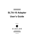
Component Data
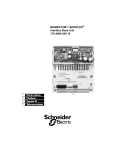
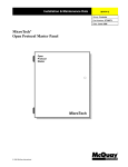
The MCG control panel layout is shown in Figure 1. The main components of the system are the
Microprocessor Control Board (MCB) and the Serial LonTalk Adapter (SLTA). These components
are mounted inside a standard NEMA 1 enclosure and interconnected by multi-conductor cables or
discrete wiring. Power for the system is provided through transformers T1 and T2. Circuit breaker
CB1, which provides overcurrent protection, can be used as an on-off switch for the panel.
Figure 1. MCG Level-2 Control Panel Layout
L1
L2
50
T2
T1
51
52
53
54
55
GRD
TB1
CB1
SLTA
FTT-A
FTT-B
GRD
B–
B+
MCB
TB2
Software ID tag
a0240
IM 661-1
5
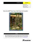
Microprocessor Control Board
The Microprocessor Control Board (MCB) is shown in Figure 2. It contains a microprocessor that is
programmed with the software required to receive, translate, and transmit data across the gateway in
either direction. The various MCB connections and components are described below.
KEYPAD/LCD DISPLAY
Figure 2. Microprocessor Control Board (MCB)
HI
LO
ADDRESS
Hex switches
FUSE 1
2
3
4
PORT A
PORT B
COMMUNICATIONS
[FUSE: BUSSMAN MCR-1/4]
RUNNING
RESET
ACTIVE
CPU
STATUS
OUTPUT 0
POWER IN
[18-24 VCT]
AC AC GND GND
DIGITAL OUTPUTS
ANALOG INPUTS
Microprocessor status LEDs
POWER FUSES
[BUSSMAN GDC-T2A]
AUX/OUT
Aux/Out Terminal Strip
The Aux/Out terminal strip provides 12 Vdc power to the SLTA. Refer to the panel’s wiring diagram
(Figure 33 or Figure 34) for more information.
Power In Terminal Strip
The MCB receives 18 Vac, center-tapped power from transformer T2 through the Power In terminal
strip. This power drives all logic and communications circuitry and the Aux/Out terminal strip. Refer
to the panel’s wiring diagram (Figure 33 or Figure 34) for more information.
Power Fuses
Two identical 2 A fuses are located to the right of the Power In terminal strip. These fuses are in the
MCB power supply circuit.
Microprocessor Status LEDs
The green, red, and amber LEDs on the MCB provide information about the operating status of the
microprocessor.
Following is the normal start-up sequence that the three status LEDs should follow when power is
applied to the MCB:
1. The red (“Reset”) LED turns on and remains on for approximately 5 seconds. During this period,
the MCB performs a self-test.
2. The red LED turns off and the green (“Running”) LED turns on. This indicates that the
microprocessor has passed the self-test and is functioning properly.
3. The amber (“Active”) LED starts flashing, indicating that the MCG’s program is active.
6
IM 661-1
For more information,
refer to the “Test
Procedures” section,
which is under
“Service Information.”
If the above sequence does not occur after power is applied to the controller, there is a problem with
the MCB or its power supply.
Table 3 and Table 4 summarize the green, red, and amber status LED indications.
Table 3. Green and Red Status LED Indication
Green LED State
Red LED State
Indication
Off
Off
No power to MCB
Off
On*
Self-test failure or power supply problem
On
Off
MCB operating normally
* For longer than 5 seconds.
Table 4. Amber Status LED Indication (Green LED On)
Amber LED State
Indication
Flashing (On 1 sec, Off 1 sec)
Normal operation
Off
Program inactive (checksums corrupt)
Hex Switches
The MCB includes two hex (hexadecimal) switches that are used to set the MCG controller’s network
address.
Figure 3. Hex Switches
HI (left) hex switch
LO (right) hex switch
A
3 4 5 6
7 8 9
A
2
3 4 5 6
BCDE
F 0 1
2
BCDE
F 0 1
7 8 9
The HI and LO hex switches are shown in Figure 3. A “hex switch setting” is defined as the HI switch
digit followed by the LO switch digit. For example, a hex switch setting of 2F would have the HI
switch set to “2” and the LO switch set to “F.”
Note: You can change the setting of a hex switch with a slotted-blade screwdriver that has a 3/32 -inch
tip. If a hex switch setting is changed, power to the MCB must be cycled in order to enter the new
setting into memory. This can be done by opening and then closing the push button circuit breaker
(CB1) in the panel.
Communication Ports
The MCB has two communication ports: port A and port B. Each port has six terminals and is set up
for both the RS-232C and RS-485 data transmission interface standards. Socketed fuses located next
to the ports protect the communications drivers from voltage in excess of 12 V. Following are brief
descriptions of each port’s function in the two MCG configurations.
Port A in “MCG-L2”: Port A is for communications with the SLTA using the RS-232C interface
standard. The communications rate is 19200 bps.
Port B in “MCG-L2”: Port B is for MicroTech network communications using the RS-485 interface
standard. The communications rate is 9600 bps.
IM 661-1
7
Port A in “MCG-OP”: Port A is for communications with (1) a PC using the RS-232C interface
standard or (2) a third-party building automation system using Open Protocol and either the RS-232C
or the RS-485 interface standard. The communications rate is 9600 bps.
Port B in “MCG-OP”: Port B is for communications with the SLTA using the RS-232C interface
standard. The communications rate is 19200 bps.
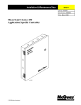
Serial LonTalk Adapter
The Serial LonTalk Adapter (SLTA) is shown in Figure 4. Manufactured by Echelon (and called
“SLTA/2” by them), it contains a Neuron chip and firmware that performs most of the translation to
and from the LonTalk protocol. The SLTA used by McQuay International contains an FTT-10 (free
topology) transceiver.
The LonWorks network connects to the SLTA at the “Network” port by means of an 8-pin, RJ-45
connector. The communications port on the MCB connects to the SLTA at the “Serial I/O” port by
means of a DB-9 connector. (Both connectors are included in the MCG.)
The SLTA receives its power from a power supply in the MCB. Note that the SLTA has a power
switch, which should always be left in the on (“1”) position.
Figure 4. Serial LonTalk Adapter (SLTA)
Power Switch
POWER
1
SERIAL I/O
0
TP/FT
10
SERVICE
SERVICE
REQUEST
NETWORK
ECHELON 73000
Top View
Bottom View
cns no. a0014
Software ID
MicroTech MCG software is factory installed and tested in each panel prior to shipment. The
software is identified by a program code (also referred to as the “Ident”), which is printed on a small
label affixed to the MCB. An example of this label is shown in Figure 5. The program code is also
encoded in the controller’s memory and is available for display on a PC equipped with Monitor
software. Using Monitor software is the most reliable way of determining the controller’s program
code.
8
IM 661-1
MCG program codification is as follows:
MCG 1 U 01 A
MicroTech Communications Gateway
Program Number
1="MCG-OP" (Level 1) Configuration
2="MCG" (Level 2) Configuration
Units
U=Universal Units
Version (numeric)
Version Revision (alphabetic)
a0136
Figure 5. Example of a Software ID Tag
P/N 860-654873B-60-0
SOFTWARE I.D.
EOS NO.
VENDOR S/N
VENDOR MDL#
DATE CODE
MCG1U01A
20.50
5554
280-60
11-95
MCB part number
Program code (“Ident”)
This edition of this manual documents revision N of the standard MCG software and subsequent
revisions of version 01 until otherwise indicated. If your MCG software has a later revision code (for
example, MCG1U01T), some of the details in this manual may not apply. However, since only very
minor software changes are considered revisions, any differences should be insignificant.
Software Compatibility
This release of MCG software allows systems using the MicroTech proprietary protocol to
communicate with the MicroTech 2000 family of LonWorks-based water source heat pump
controllers.
The current software compatibility for standard MCG software is summarized in Table 5. The
wildcard character ( > ) can be any letter.
If you have a version of MicroTech 2000 unit controller software that is later than the compatible
programs shown in Table 5, it is likely that program MCG > U01 > is compatible with it; however, it
may not be. To find out for sure, contact McQuayService.
Table 5. Program Code MCG*U01N Software Compatibility
Unit Type
Compatible MicroTech 2000 Programs
Incompatible MicroTech 2000 Programs
HP
WHPE1D
none
Note: The MCG cannot be used with LonMark compatible MicroTech 2000 HP controllers.
Applying the MicroTech Communications Gateway
Networks that include both MicroTech 2000 and MicroTech controls require a MicroTech
Communications Gateway. The MCG translates between the proprietary MicroTech network protocol
and LonTalk, the protocol of MicroTech 2000 unit controllers. Devices using the MicroTech protocol
include (1) unit and auxiliary controllers in the MicroTech family, (2) PCs equipped with MicroTech
Monitor software, and (3) building automation systems by other manufacturers using Open Protocol.
IM 661-1
9
(The term MCG is used to refer to MicroTech Communication Gateways in general when the
particular application or variation is not important.)
McQuay International produces two variations of the MCG. One is a level-1 controller (referred to as
an MCG-OP), and the other is a level-2 controller (referred to as an MCG-L2). The MCG-OP is the
Open Protocol interface between a BAS network of an Open Protocol partner and MicroTech 2000
unit controllers. The MCG-L2 is used in both MicroTech BAS and Open Protocol networks. It is the
interface between the level-1 MicroTech controller and MicroTech 2000 unit controllers.
Open Protocol networks require only one MCG, either an MCG-OP or an MCG-L2. This MCG
handles all gateway functions. MicroTech BAS networks require two MCG-L2s. The gateway
functions are shared between two configurations of the MCG-L2. The one configured as an
MCG-Monitor handles all read and write requests from the Monitor program (This function is similar
to the Open Protocol function of the MCG-OP). The other configured as the MCG-LMP handles all
network read and write requests from the MicroTech level-1 controller. You specify the configuration
for each in the MicroTech Monitor for Windows program.
See Figure 6 through Figure 9 for typical applications in which MicroTech 2000 products are used.
The table contains a legend for the figures.
Symbol
Description
BAS
Building automation system
HP
Water source heat pump
LWC
Loop Water Controller
OPM
Open Protocol Master
ART
Applied rooftop unit
LMP
Local Master Panel
NMP
Network Master Panel
MicroTech network wiring
MicroTech 2000 (LonWorks FTT-10) network wiring
Interoperable Systems
Figure 6 through Figure 8 shows typical interoperable system applications. In these applications,
MicroTech 2000 controllers are integrated into a third-party BAS, which includes a human-machine
interface such as a PC. The systems are interoperable because the McQuay International equipment
and the BAS are able to communicate through a common protocol.
Pure LonWorks
In Figure 6, which shows the ideal interoperable system, the third-party BAS is capable of
implementing LonWorks technology. Because the BAS uses LonWorks, the communications protocol
is LonTalk, and thus the MCG is not required.
Figure 6. Typical Interoperable System Using LonTalk Interface
MicroTech 2000
BAS by others, implementing
L ONW ORKS Technology
L ON W ORKS Subnet
HP
HP
HP
L ON M ARK
HP
HP
HP
HP
HP
HP
HP
To additional
L ONW ORKS
devices
a0137
10
IM 661-1
No MCG Required: LonTalk and LonMark™
In Figure 6, which shows the ideal interoperable system, the third party BAS is capable of
implementing LonWorks technology, and the MicroTech 2000 products are LonMark certified.
Because the BAS uses LonWorks, the communications protocol is LonTalk, and thus the MCG
cannot be used. LonMark-certified products conform to interoperability standards that are
increasingly being accepted and used throughout the HVAC industry. These standards define the
minimum requirements for the variables passed over the network (e.g., supply air temperature for a
heat pump) and their formats (e.g., units of degrees Celsius). The common LonTalk protocol allows
the different products to “speak the same language”; the LonMark standards allow different products
to “know what to say to each other” with a minimum amount of systems-integration effort.
Note: LonMark-certified MicroTech 2000 products are not yet available. The software for the
MicroTech 2000 water source heat pump is not LonMark-certified.
Open Protocol: MicroTech 2000 Only
Figure 7 shows an interoperable system in which the third-party BAS is communicating with
MicroTech 2000 controllers through a single connection. Because the BAS in this application is not
capable of implementing LonWorks technology, the MCG and Open Protocol are required. The
“MCG-OP” controller is used since the MCG is substituting for an OPM.
In an Open Protocol environment, the refresh rate for each point accessed through an MCG depends
on the total number of points polled. Each MCG can communicate with a maximum of 64 controllers.
Temperature control companies should set limits on how many controllers are connected to each
MCG and how many points each controller polls. In general, no more than 32 controllers should be
connected to an MCG and each controller should poll no more than 20 points. This gives acceptable
refresh rates for most systems. However, you may want to reduce the number of controllers or the
number of points to achieve the refresh rate you want.
See “Open Protocol:
MicroTech and
MicroTech 2000 Mix”.
If other unit or auxiliary controllers in the MicroTech family are integrated into the system, a separate
connection from the BAS is required for each MicroTech controller.
Figure 7. Typical Interoperable System Using Open Protocol Interface to MicroTech 2000
Equipment Only
BAS by Others
MicroTech 2000
MicroTech
Level 1
Open Protocol
MCG
“MCG-OP” panel
L ON W ORKS Subnet
HP
HP
HP
HP
HP
HP
HP
HP
HP
HP
Up to
32 HPs
per MCG
a0019
Open Protocol: MicroTech and MicroTech 2000 Mix
Figure 8 shows an interoperable system in which the third-party BAS is communicating with a
mixture of MicroTech and MicroTech 2000 products through a single connection. The OPM is
required because the BAS is communicating with more than one MicroTech product through a single
connection. (The MCG is considered a MicroTech product.) The MCG is required because the BAS
in this application cannot implement LonWorks technology. The “MCG-L2” panel is used here since
the MCG is not substituting for an OPM. For best performance, connect no more than 32 MicroTech
2000 controllers to MCG-L2 and poll no more than 20 information points per controller.
IM 661-1
11
Note: The LWC in Figure 8 is shown integrated via a separate BAS connection because quicker
response times result. Though not recommended, it is also possible to use the LWC as a level-2 slave
to the OPM. The BAS is responsible for all communications between the LWC and the MCG.
Figure 8. Typical Interoperable System Using Open Protocol Interface to MicroTech and
MicroTech 2000 Equipment
BAS by Others
Level 1
Open Protocol
MicroTech
“MCG-L2” panel
OPM
Level 2
HP
ART
MCG
MicroTech 2000
LWC
HP
HP
HP
HP
HP
To additional
Level-2
Controllers
LonWorks Subnet
Up to 64 HPs
per MCG
HP
HP
HP
HP
HP
HP
HP
HP
HP
HP
HP
a0020
MicroTech BAS
Figure 9 shows a typical MicroTech BAS application with a mixture of MicroTech and MicroTech
2000 products. In these applications, MicroTech 2000 controllers are integrated into a MicroTech
BAS, which includes a PC equipped with MicroTech Monitor™ for Windows software. In the case of
MicroTech 2000 controllers for water source heat pumps, the MCG effectively substitutes for a Local
Master Controller (LMC), which is included in LMPs and some NMPs.
For defintions of
MCG terms, see
“Applying the
MicroTech
Communications
Gateway.”
12
Network functions are shared between two MCGs. One configured as the “MCG-Monitor ” controls
read and write requests from the PC to the MicroTech 2000 unit controllers. The other configured as
the “MCG-LMP” controls alarms, network read and write requests, and time schedules sent to the
MicroTech 2000 unit controllers from the NMP. Both MCGs are required and must be connected to
the LonWorks subnet.
IM 661-1
Figure 9. Typical MicroTech-Only System with MicroTech and MicroTech 2000 Equipment
Level 1
PC containing MicroTech
Monitor for Windows
NMP
“MCG-LMP”
MicroTech
“MCG-Monitor”
To additional
level-2 controllers
MCG
Level 2
LMP
MCG
LWC
ART
Up to 64 HPs
per LMP
Level 3
MicroTech 2000
HP
HP
HP
HP
HP
HP
HP
HP
LonWorks
Subnet
Up to 64 HPs
per MCG
HP
HP
HP
HP
HP
HP
HP
HP
HP
HP
HP
a0021
Network Architecture
Any network that includes an MCG contains two types of network architecture: MicroTech, which is
a master-slave type, and MicroTech 2000 (LonWorks), which is a peer-to-peer type. The MCG is the
gateway between the two network types.
MicroTech Family
All controllers in a MicroTech network are assigned a logical “level”: level 1, level 2, or level 3. All
MicroTech networks must have one (and only one) level-1 controller to coordinate communications.
Multiple level-2 controllers can be connected to the level-1 controller with a communications trunk,
an isolated section of the daisy-chained network. Multiple level-3 controllers can be connected to a
level-2 controller with another trunk. For general information on wiring a MicroTech network, refer
to the installation manual provided with the level-1 controller.
MicroTech 2000 Family
For information on
wiring the subnet,
see the “Field Wiring”
section.
The network architecture that is currently used with the MCG and the MicroTech 2000 family of unit
controllers is a simplified form of LonWorks architecture. The MCG and all MicroTech 2000
controllers connected to it are part of the same subnet. The SLTA and each MicroTech 2000
controller are nodes on the subnet. A node is any device that contains a Neuron chip
From the MicroTech side of the MCG, the MicroTech 2000 nodes appear as level-3 slaves. Thus the
Open Protocol and MicroTech BAS functions in the NMP and PC operate the same way they do for
MicroTech controllers.
IM 661-1
13
Installation
Panel Location and Mounting
The MCG is suitable for indoor use only. Table 6 lists allowable temperature and humidity ranges.
Locate the panel (or panels) at a convenient height, and allow adequate clearance for the door swing.
Mount each panel to the wall with screws or bolts. It weighs approximately 50 pounds. The panel has
four 1/4 -inch keyslot openings at the corners. Panel dimensions are shown in Figure 10.
The panel is equipped with special door hinges that have a friction adjustment screw. By adjusting
this screw, you can prevent the door from swinging open or closed unexpectedly.
Table 6. MCG Panel Environmental Specifications
Panel State
Temperature
Relative Humidity
Operating
32 – 100°F (0 – 37°C)
25 – 95% (noncondensing)
In storage
–4 – 140°F (–20 – 60°C)
0 – 95% (noncondensing)
Figure 10. MCG Panel Dimensions
7/8 [22] Dia. knockouts (4 on left and right sides)
Hinge friction adjustment screw
18-1/4
[464]
1/4 [6] Dia. mounting slots (4)
17-3/8
[441]
12-3/4
[324]
20
[508]
7-1/4
[184]
1-3/4
[44]
2 [51]
1 [25]
16 [406]
4 [102]
18 [457]
Left Side View
Front View
1-5/8
[41]
7/8 [22] Dia. knockouts
(4 on top and bottom)
1-7/8 [48]
2
[51]
6-5/8 [168]
11-3/8 [289]
16-1/8 [410]
Note: Dimensions are in inches
(millimeters in brackets).
Bottom View
a0138
14
IM 661-1
Field Wiring
Following are descriptions of the various field wiring requirements and options. All possible fieldwiring connections are shown in Figure 13.
The panel is divided into high and low voltage sections by a sheet metal barrier. Pass power wires
only into the high voltage section, and network wires only into the low voltage section. Wiring
penetrations must be made only through the 7/8 -inch knockouts provided.
Caution: Do not pass network wires through the high voltage section or high voltage wires through
the low voltage section.
Note: Wiring must comply with the National Electrical Code and all local codes and ordinances. The
warranty is void if the field wiring is not in accordance with these instructions.
Power
!
WARNING
Electric shock hazard.
Can cause personal injury or death.
This equipment must be properly grounded.
All protective deadfront panels must be reinstalled and secured when power wiring is
complete.
The MCG panel requires 115 Vac power, which should be connected to terminals L1 and L2 in the
high voltage section of the panel. The panel must be properly grounded by connecting the ground lug
(GRD) to earth ground. Refer to Figure 13. Power wiring must be sized to carry at least 5 amps.
To gain access to the high voltage section, remove the deadfront barrier. It is attached to the panel
with three 5/16 -inch hex screws. Replace this deadfront when the wiring is complete.
The panel is internally protected with a 0.5 amp circuit breaker (CB1), which is located inside the
panel on the underside of the high voltage section (see Figure 1). This push-button circuit breaker can
also be used as an on-off switch for the panel. When the push button is in, the panel should be
energized. When the push button is out, the panel should be de-energized. Note that a white ring on
the switch shaft is visible when the push button is out.
Network Communications: MicroTech 2000 Side
See the “Cable
Specification” section
for cable details.
The MCG’s SLTA and all MicroTech 2000 controllers are equipped with an FTT-10 transceiver for
network communications. This transceiver allows for (1) free topology network wiring schemes using
twisted pair (unshielded) cable and (2) polarity insensitive terminations at each node. This
combination of features greatly simplifies installation and reduces network commissioning problems.
It also allows nodes to be added in the future with little regard for existing cable routing. The
communications rate on an FTT-10 network is 78 kbps.
As shown in Figure 11, free topology means that the following network topologies are possible:
•
Bus
•
Ring
•
Star
•
Any combination of Bus, Ring, and Star
Note: Limitations to wire lengths apply and must be observed.
IM 661-1
15
Figure 11. Free Topology Networks
TR
Bus
TR
TR
Ring
Star
TR
TR = 52 ohm
Combinations
A network segment is any part of the free topology network in which each conductor is electrically
continuous. Each of the four diagrams in Figure 11 is a segment. Some applications may require two
or more segments; see “Free Topology Restrictions” below. If necessary, segments can be joined with
FTT-10-to-FTT-10 physical layer repeaters, which are available from third-party vendors. See Figure
12.
Figure 12. Combining Network Segments With a Repeater
FTT-10
TR
FTT-10
Repeater
TR
TR = 52 ohm
Free Topology Restrictions
Although free topology wiring is very flexible, there are restrictions:
1. The maximum number of nodes per segment is 64 (not including the SLTA).
The maximum number of MicroTech 2000 controllers per MCG-L2 pair (MicroTech BAS) or
per MCG-OP (Open Protocol: 32 is recommended maximum) is also 64. So when an MCG is
being used, this 64-unit limit cannot be increased by installing a repeater.
16
IM 661-1
Figure 13. Typical Field Wiring Diagram for MicroTech BAS (Free Topology Shown)
MCG-L2
TB1
Hot
115 V ac power
L1
Neutral
L2
GRD
SLTA
52.3 Ohm
Resistor
TB2
TB2
FTT-A
WHT
B+
FTT-B
Port B
BLK
B–
GRD
MCG-L2
TB1
Hot
115 V ac power
L1
Neutral
L2
GRD
SLTA
Resistor
Removed
See notes 4 & 5
TB2
TB2
FTT-A
B+
FTT-B
Port B
WHT
MicroTech BAS
BLK
B–
GRD
1.
“B”
“A”
FTT-10
unit controller
MicroTech 2000
“B”
“A”
FTT-10
“B”
“A”
FTT-10
“B”
“A”
FTT-10
unit controller
unit controller
MicroTech 2000
MicroTech 2000
MicroTech 2000 network communications terminations are polarity
MicroTech 2000
“B”
“A”
FTT-10
MicroTech 2000
unit controller
4.
Notes:
unit controller
“B”
“A”
FTT-10
unit controller
MicroTech 2000
“B”
“A”
FTT-10
“B”
FTT-10
“B”
“A”
FTT-10
unit controller
“A”
MicroTech 2000
MicroTech 2000
unit controller
MicroTech 2000
unit controller
See notes 1, 2 & 3
Twisted, shielded pair cable must meet the following minimum
requirements: 300 V, 60°C, 20 AWG, polyethylene insulated, with a PVC
insensitive. Field terminals are as follows:
outer jacket and drain wire (Belden 8762 or equivalent). Some local codes
may require the use of plenum rated cable.
FTT-10 field terminal
MicroTech 2000 unit controller
Water source heat pump
2.
“A”
“B”
TB1-5
TB1-6
When making splices and multiple-wire terminations, always match wire
color to reduce the risk of shorts.
This precaution is especially important
when wiring ring topologies.
3.
Twisted pair cable for a MicroTech 2000 network must be NEMA “Level 4”
or approved by Echelon (Connect-Air W221P-1002 [PVC], W221P-2001
[plenum], or equivalent). Maximum node-to-node distance is 1312 ft
(400 m). Total cable length must not exceed 1640 ft (500 m).
IM 661-1
5.
Cable length must not exceed 5000 ft (1524 m).
Legend
FTT-B
Field wiring terminal
Field wiring: discrete
Field wiring: twisted pair cable
Field wiring: twisted, shielded pair cable
with drain wire
a0023
17
Figure 14. Typical Field Wiring Schematic for Open Protocol System (Free Topology Shown)
MCG-OP
115 Vac power
TB1
Hot
L1
Neutral
L2
GRD
SLTA
52.3 Ohm
Resistor
TB2
TB2
FTT-A
WHT
A+
Port A
FTT-B
Third Party BAS
BLK
A–
GRD
See notes 4 & 5
1.
4.
“B”
“A”
FTT-10
unit controller
MicroTech 2000
“B”
“A”
FTT-10
“B”
“A”
“A”
FTT-10
“B”
FTT-10
unit controller
unit controller
MicroTech 2000
unit controller
MicroTech 2000
Notes:
MicroTech 2000
“B”
“A”
FTT-10
“B”
“A”
unit controller
FTT-10
“B”
MicroTech 2000
FTT-10
“B”
FTT-10
unit controller
MicroTech 2000
“A”
“A”
“A”
“B”
unit controller
unit controller
FTT-10
MicroTech 2000
MicroTech 2000
MicroTech 2000
unit controller
See notes 1, 2 & 3
Twisted, shielded pair cable must meet the following minimum
MicroTech 2000 network communications terminations are polarity
requirements: 300 V, 60°C, 20 AWG, polyethylene insulated, with a PVC
insensitive. Field terminals are as follows:
outer jacket and drain wire (Belden 8762 or equivalent). Some local codes
may require the use of plenum rated cable.
FTT-10 field terminal
MicroTech 2000 unit controller
Water source heat pump
2.
“A”
“B”
TB1-5
TB1-6
When making splices and multiple-wire terminations, always match wire
color to reduce the risk of shorts.
This precaution is especially important
when wiring ring topologies.
3.
Twisted pair cable for a MicroTech 2000 network must be NEMA “Level 4”
or approved by Echelon (Connect-Air W221P-1002 [PVC], W221P-2001
[plenum], or equivalent). Maximum node-to-node distance is 1312 ft
(400 m). Total cable length must not exceed 1640 ft (500 m).
5.
Cable length must not exceed 50 ft (1524 m).
Legend
FTT-B
Field wiring terminal
Field wiring: discrete
Field wiring: twisted pair cable
Field wiring: twisted, shielded pair cable
with drain wire
a0059
2.
18
The maximum node-to-node distance is 1312 ft (400 m).
The longest cable path between any possible pair of nodes on a segment must not exceed the
maximum node-to-node distance. If two or more paths exist between a pair of nodes (e.g., a loop
topology), the longest path should be considered. Note that in a bus topology, the longest nodeto-node distance is equal to the total cable length.
IM 661-1
3.
The maximum total cable length is 1640 ft (500 m).
a. The total length of all cable in a segment must not exceed the maximum total cable length.
b. One 52.3-ohm (0.25 W, 1%) termination resistor is required in each segment.
c. A termination resistor is factory installed in the MCG across terminals FTT-A and FTT-B,
so in most cases, you don’t need to worry about this requirement.
d. If you install a repeater and another segment, you must obtain and install a termination
resistor in that segment. The termination resistor can be located anywhere in the segment.
e. When you install more than one MCG on the same segment (MicroTech BAS networks),
you must remove the resistors from one MCG.
Extending Cable Length with Special Bus Topology
You can extend the maximum total cable length without using a repeater by using doubly-terminated
bus topology instead of free topology. See Figure 15. The trade-offs are (1) this special bus topology
must be rigorously followed during the installation and subsequent retrofits and (2) two termination
resistors must be installed at the ends of the bus.
Figure 15. Doubly-Terminated Bus Topology Network
Stub
TR
TR
TR = 105 ohm
The restrictions on doubly-terminated bus topology are as follows:
1. The maximum number of nodes per segment is 64 (not including SLTA).
2. The maximum total bus length depends on the wire size (see “Cable Specification” for details):
3.
4.
Wire Size
Maximum Cable Length
22 AWG
4590 ft (1400 m)
16 AWG
8855 ft (2700 m)
The maximum stub length is 9.8 ft (3 m).
A stub is a piece of cable that is wired between the node and the bus. See Figure 15. Note that if
the bus is wired directly to the node, there is no stub, and thus the stub length is zero. If you are
wiring to a field terminal strip on a unit (e.g., HP), be sure to account for any factory wiring
between the terminal strip and the MicroTech 2000 controller. This wiring is considered part of
the stub.
Two 105-ohm (0.25 W, 1%) termination resistors are required in each segment. One resistor
must be located at each end of the bus.
Note that the 52-ohm resistor in the MCG, which is factory installed across terminals FTT-A and
FTT-B, must be removed. If the bus includes two MCGs, the resistor in each MCG must be
removed.
Cable Specification
The twisted-pair network communications cable for MicroTech 2000 (LonWorks FTT-10) networks
must (1) be approved by Echelon or (2) meet the “Level 4” cable specification for 22 AWG (0.65
mm) wire, which was originally defined by NEMA. Some local codes or applications may require the
use of plenum rated cable. The following cables meet this specification:
IM 661-1
19
Vendor
Part no.
Wire size & type
Connect-Air International
(Phone: 206-813-5599)
W221P-1002
W221P-2001
22 AWG, PVC
22 AWG, plenum
Belden
(Phone: 317-983-5200)
8471 85102
16 AWG, PVC
16 AWG, plenum
Do not install the cable in the same conduit with power wiring. The temperature of the cable must not
exceed 131°F (55°C).
Note: Ideally, one continuous piece of cable should connect any two controllers. This reduces the
risk of communications errors. If the cable must be spliced, use crimp-type butt connectors (good) or
solder (best). Do not use wire nuts.
Wiring Instructions
Wiring a MicroTech 2000 network is simplified by the following:
1. Free topology may be used.
2. Only two terminations are required at each node.
3. Those terminations may be made without regard for polarity.
4. If you use two MCGs, connect them together in parallel and remove the terminating resistor from
one of them.
MicroTech 2000 controllers are equipped with field terminals for the network communications
terminations, which are summarized in Table 7. (Internal factory wiring connects the node to the field
terminals.)
Table 7. Network Communications Field Wiring Terminals
MicroTech 2000 Controller
Terminal “A”
Terminal “B”
MCG
FTT-A on TB2
FTT-B on TB2
HP
5 on TB1
6 on TB1
Network wiring is completely independent from controller addressing. Therefore, the networked
controllers can be wired in any order. Thus an electrician can wire the network and a technician—
who has no knowledge of the wiring—can address the controllers later, during the commissioning
process.
Use the following guidelines as you wire the network:
•
Before beginning, unplug the RJ-45 connector from the “Network” port on the SLTA in the
MCG.
•
Observe the topology restrictions described above.
•
Use care to assure that no shorts or opens exist in the network.
•
Make certain to connect to the proper terminals on the HP.
Note: Voltages are present on some field wiring terminals of the HP. If the communications wire is
connected to the wrong terminals, it can destroy the communications components of all controllers
connected to the communications wire. These boards are not replaced under warranty.
The resistance across the conductors from the termination resistor(s) should be approximately
52 ohms, but this resistance appears on an ohmmeter only when all nodes are disconnected from the
network cable. This is true because the impedance across an unpowered FTT-10 transceiver is
approximately 6 ohms. Because disconnecting all nodes may be a difficult and time consuming task,
we recommend not doing it unless communications problems are discovered during the
commissioning process.
20
IM 661-1
•
When making wire splices and multiple-wire terminations, always match wire color to reduce the
risk of shorts. This precaution is especially important when wiring ring topologies.
•
Though free topology allows for very flexible, ad hoc wiring, it is recommended that the
installing contractor record the physical locations of the cable runs and the controllers on a
floor plan. This facilitates troubleshooting any network communications problems that may occur
during installation or in the future.
•
By looking at the internal factory wiring, assure that each node (except SLTA) is connected to
the network. The connection at a MicroTech 2000 controller is typically an “insulationdisplacement” type (IDC) plug-in connector. These connectors should be connected to their
controllers. Since controller addressing can be done remotely, this eliminates the need for a
technician to return to each unit during the commissioning process.
Note: This guideline is the opposite of what is recommended for a MicroTech network.
Network Communications: MicroTech Side
See the “Cable
Specifications”
section for details.
MCG-L2 panels” (level-2) require network communications wiring on the MicroTech side of the
gateway. As shown on the panel wiring diagram, the twisted, shielded cable should be wired to
terminals B+, B–, and GND on terminal block TB2. For more information on wiring the MicroTech
side of the network, see the installation manual that was supplied with the level-1 controller; for
example, the MicroTech Network Master Panel (NMP) or Open Protocol Master (OPM).
Note: Network communications wiring requirements for MicroTech 2000 networks are very
different from those for MicroTech networks. For example, in a MicroTech network, free topology
does not apply (a bus topology must be used), and twisted pair, unshielded cable cannot be used.
Network Commissioning
This section discusses network commissioning for MicroTech 2000 networks in which there is an
MCG. It does not discuss the commissioning of a MicroTech network. For information on that, refer
to the installation manual supplied with the level-1 controller (e.g., NMP, OPM, or CSC).
The purpose of commissioning a MicroTech 2000 network is to establish and verify communications
between the MCG and its associated unit controllers. (It is not to establish and verify unit operation.)
Network commissioning should be done after unit check test and start procedures have been
completed.
!
NOTICE
Before any unit is allowed to operate, it must be commissioned in accordance with the
instructions in the MicroTech unit controller installation literature (see Table 1) and the modelspecific unit installation literature. In addition, the MCG must be set up so that it can perform
the proper data translation for its associated units. This setup is described below in “Overview
of Procedure.”
Network Management
In addition to performing protocol translation, the MCG serves as a network management tool, which
holds the network database. A network management tool allows you to configure a LonWorks
network. When you configure a MicroTech 2000 network, you simultaneously address the controllers
and set up the network database. A network database simply contains information about the network’s
configuration. In the MCG, this is essentially a table that lists each MicroTech 2000 controller and its
logical address (see Figure 18).
IM 661-1
21
MicroTech 2000 controllers are assigned logical addresses by the network management tool; there are
no hex switches as there are on MicroTech controllers. Since the network management tool
communicates over the network, you can perform addressing and commissioning at the same time.
In conjunction with a PC equipped with the appropriate Monitor software, the MCG provides the
following network management tool features:
•
Automatic node installation (addressing)
•
Manual node installation (addressing)
•
Automatic address conflict resolution
•
Service pin message acknowledgment
•
Wink
These features are described below in “Node Installation.”
There are other network management tools available; for example, a PC equipped with a PCLTA card
and LonMaker™ software. If you want, you can use one of the other tools instead of the MCG. (In
this case, the MCG must still be set up so that proper data translation occurs.
Required Tools
To commission the network, you need the following tools:
1. Voltmeter
2. Ohmmeter
3. PC equipped with Monitor software for the MCG
4. Cable to connect the PC to a MicroTech controller
For more information on the PC and the cable, see “PC Access” below.
About the Network Address
For network communications to occur, each controller in the network must have a unique network
address. The network address has two parts: subnet address and node address. Each part is a two-digit
hexadecimal number. For example, a unit at address 01.0F has a subnet address of 01(hexadecimal)
and a node address of 0F(hexadecimal) (decimal 15). The first digit in each part is called the HI digit,
and the second digit is called the LO digit. Thus for the node address 0F(hexadecimal), the HI digit is
“0” and the LO digit is “F.” Table 8 is a hexadecimal to decimal conversion guide.
Figure 16. MicroTech 2000 Network Address
Subnet HI digit
Subnet LO digit
Node HI digit
Node LO digit
01.0F
22
IM 661-1
Table 8. Hexadecimal to Decimal Conversion Guide
Hex
Dec
Hex
Dec
Hex
Dec
Hex
Dec
01
1
11
17
21
33
31
49
02
2
12
18
22
34
32
50
03
3
13
19
23
35
33
51
04
4
14
20
24
36
34
52
05
5
15
21
25
37
35
53
06
6
16
22
26
38
36
54
07
7
17
23
27
39
37
55
08
8
18
24
28
40
38
56
09
9
19
25
29
41
39
57
0A
10
1A
26
2A
42
3A
58
0B
11
1B
27
2B
43
3B
59
0C
12
1C
28
2C
44
3C
60
0D
13
1D
29
2D
45
3D
61
0E
14
1E
30
2E
46
3E
62
0F
15
1F
31
2F
47
3F
63
10
16
20
32
30
48
40
64
After the subnet address is set in the MCG, the MCG automatically assigns it to each of its associated
nodes during the node installation.
In most cases, the node address and its associated controller is defined and documented on a schedule
before network commissioning begins. The system engineer should keep in mind the following rules
when doing this:
•
The node addresses of MicroTech 2000 HP controllers must start at 01 and continue
consecutively.
•
In a MicroTech BAS network, the maximum number of nodes is 40(hexadecimal) (decimal 64)
for each MCG pair.
•
In an Open Protocol network, no more than 20(hexadecimal) (32 decimal) nodes should be
polled for each MCG.
•
There must be no gaps in the sequence and no duplicate settings.
Overview of Procedure
1.
2.
3.
4.
IM 661-1
Assure that all units have been through the factory specified check, test, and start procedure.
If an HP has not been through this procedure, it should not be powered up because mechanical
damage may occur. Since units must be powered during network commissioning, do the check,
test, and start procedure on all HPs prior to the network commissioning.
Verify the network wiring.
Check that the network wiring was done according to the instructions in “Field Wiring”. All
MicroTech 2000 controllers are connected to the network cable, and all units have power.
If this is MicroTech BAS network, verify that the factory-installed resistor across FTT-A and
FTT-B has been removed from one of the MCGs.
Use a voltmeter to check for stray voltage on the network.
a. At the MCG, place one lead on the control panel chassis (ground), and check the voltage at
the FTT-A and FTT-B field terminals. There should be no voltage.
b. If there is, check the network wiring for sources of stray voltage.
Connect the PC and start the Monitor program.
23
For basic information
on how to load and
use the Monitor
program, see the
user’s manual that
was supplied with it.
5.
6.
For defintions of
MCG terms, see
“Applying the
MicroTech
Communications
Gateway.”
A PC is required to set up the MCG and do some of the optional network management methods.
The connection point depends on the application. See “PC Access” below for information.
At the MCG, plug the RJ-45 connector into the Network port on the SLTA.
Set the subnet address at the MCG.
The way the subnet address is set depends on the MCG’s configuration. After you have set the
subnet address, you must reset the MCB. (This reconfigures the SLTA.) You can reset the MCB
by (1) cycling power to the panel or (2) changing the Soft Reset? variable to “Reset.”
“MCG-L2”
In a MicroTech BAS network, each HP communications bus must be connected to two
MCGs. One MCG is configured as an MCG-Monitor and the second is configured as an
MCG-LMP. These two MCGs serve different communications functions, and both must be
present and active for reliable network communications. The subnet address (which is a
LonWorks address) must be the same for both, but each MicroTech network address must be
different. The hex switches on the two MCGs must be set to different values.
The LonWorks subnet address is determined by the hex switch value of the MCG-Monitor.
Therefore, the LonWorks subnet address for all HPs and the MicroTech network level-2
address of the MCG-Monitor are the same. For example, if a the hex switch setting is 02, its
MicroTech network address is 02.00 and its MicroTech 2000 subnet address is 02. The
MCG-Monitors hex switches should have been set when the MicroTech network was
commissioned.
The MCG-LMP has different LonWorks subnet and MicroTech network addresses. The
LonWorks subnet address of the MCG-LMP is determined by its Subnet Address variable
which is set by using the Monitor program and should match the subnet address of the MCGMonitor. For more information, see “MCG Setup Variables” below. The MicroTech network
address of the MCG-LMP is set by using the hex switches, and should have been done during
the MicroTech network commissioning.
“MCG-OP”
The subnet address is set in the MCG’s Subnet Address variable, which is set with the
Monitor program. Unlike all other MicroTech controllers, the hex switches on the MCG-OP
are ignored (unless they are set to FF). No matter what value the hex switches are set to, the
MicroTech network address of the MCG-OP is 00.00. In most cases, the default subnet
address 01 need not be altered. For more information, see “MCG Setup Variables”.
7.
Set up the MCG. Use the Monitor program to set the following variables in the MCG:
a. Gateway Configuration (MCG Setup screen)
b. Number Of Controllers (MCG Setup screen)
c. Node x Location Description, where x is the node address (Network Database screen)
Note: The Node Location Description variables are for documentation purposes only.
Setting them is optional.
For more information
on these and other
MCG variables, see
“MCG Setup
Variables” below.
24
8.
9.
Do not set the Unit Type variables yet; they are set after the controller addresses are assigned.
Verify that the Serial LonTalk Adapter Status variable shows “OK–Configured.” If it does not,
see “Troubleshooting the SLTA” in the “Test Procedures” section.
For each MicroTech 2000 controller, (1) assign an address, (2) verify communications, and (3)
verify the address.
These three tasks are collectively called “installing a node.” There are four ways to install a node:
IM 661-1
See “Node
Installation” below for
detailed information
on each method.
See the “Using the
MicroTech Wall
Sensor” section
below for more
information.
a. Auto-Install: Specific method
b. Auto-Install: Incremental method
c. Manual-Install: Remote/Local method
d. Manual-Install: Remote method (readdress only)
In most cases, node installation involves using the tenant override button and Status LED at each
unit’s wall sensor.
10. Set the Unit Type variables in the MCG. This step can be done for each node after it is installed
or after all the nodes are installed.
The Unit Type variables tell the MCG how to interpret and route data going to or coming from
the unit controllers.
Water source heat pumps are manufacture in four types:
CCH
Ceiling hung
Single compressor and dual compressor
FCV
Small vertical
Single compressor only
WM
Console units
Single compressor only
LHP
Large vertical
Single compressor and dual compressor
Set the Unit Type variables according to the following guidelines:
Unit Type setting
Guidelines
WSHP
FCV
WM
CCH, Single compressor units only
LHP
CCH, Dual compressor units only
LHP, Single and dual compressor units
Note: The node installation process automatically changes the Unit Type variable from “N/A” to
the default setting, “WSHP.” Be sure to change it to LHP if necessary.
11. For MicroTech BAS applications, set up the slave list in the NMP.
For MicroTech 2000 HP controllers, the MCG-LMP is emulating a MicroTech Local Master
Controller. Therefore, the MCG-LMP should be designated as “WSLMP” in the NMP’s slave list
and its Alarm Address variable should be set equal to the MicroTech network level-2 address of
the associated MCG-Monitor. The MCG-Monitor is used only for Monitor communications and
should be declared as “N/A” in the NMP’s slave list. Its alarm address variable is not used and
may be left at its default value.
PC Access
See the “Applying the
MCG” section for
more information.
IM 661-1
During the network commissioning process, PC access to the MCG controller is required. The
connection point for the PC and the form of Monitor software supplied depends on the application.
The following table summarizes these situations:
Application
MCG Panel config.
Monitor software
PC connection at
Open Protocol: MicroTech 2000
only (Figure 7)
MCG-OP
Standard Open Protocol (DOS
based)
Port A on MCG
Open Protocol: MicroTech and
MicroTech 2000 mix (Figure 8)
MCG
Standard Open Protocol (DOS
based)
Port A on OPM
MicroTech BAS (Figure 9)
2 MCGs (MCG-Monitor
and MCG-LMP)
Custom (Windows based)
Port A on NMP
25
For the two Open Protocol applications, the PC is connected only during the commissioning process.
It is typically a laptop (see Table 9 for specifications). For the MicroTech BAS application, the PC is
usually the permanent on-site PC. However, it could also be a laptop temporarily connected to the
level-1 controller or another level-2 controller. Note that you can connect directly to the “MCG-OP”
panel, but you cannot connect directly to the “MCG-L2” panel.
Table 9. PC Specification for Network Commissioning
Preferred Configuration
Minimum Configuration
Pentium processor
386SX processor
8 MB of RAM or better
4 MB of RAM
3½” floppy disk drive
3½” floppy disk drive
Serial port (9 pin male; Com1 or Com2)
Serial port (9 or 25 pin male; Com1 or Com2)
Super VGA graphics capability
VGA graphics capability
Bus mouse or trackball (for Windows-based Monitor only)
Serial mouse or trackball* (for Windows-based Monitor
only)
MS-DOS® 6.2
MS-DOS® 5.0
Microsoft® Windows® 3.1 (for Windows-based Monitor
only)
Microsoft® Windows® 3.1 (for Windows-based Monitor
only)
MicroTech® Monitor™ software for MCG
MicroTech® Monitor™ software for MCG
* If a serial pointing device is used, there must be another serial port (Com1 or Com2) available for connecting the PC to the
MicroTech controller.
The MCG’s Monitor software is available in two forms: DOS based and Windows based. The DOS
version is part of the standard Monitor software package for Open Protocol commissioning. The
Windows version is included in Monitor software packages that are custom made for MicroTechBAS applications.
PC Connection Cable
An RS-232 communications cable kit that allows a PC to be directly connected to any MicroTech
controller is available from McQuay International. The part number is 0057186802. The cable has a
female DB-9 connector for connection to the PC’s 9-pin serial port. (If the PC has a 25-pin serial
port, obtain an adapter.) The cable length is 12 feet.
MCG Setup Variables
The MCG’s setup variables can be accessed with a PC running the appropriate Monitor software. See
Figure 17. (Windows-based Monitor is shown; DOS-based Monitor is similar.) After the network is
commissioned, most variables should not need to be changed unless a HP controller is added or
deleted.
26
IM 661-1
Figure 17. MCG Setup Screen
a0241
Gateway Configuration
For defintions of
MCG terms, see
“Applying the
MicroTech
Communications
Gateway.”
The Gateway Configuration variable tells you what the MCG’s configuration is—“MCG-LMP” (level
2), “MCG-Monitor” (level 2) or “MCG-OP” (level 1). An MCG-OP has software that only works in
an Open Protocol environment and has internal wiring set up for this purpose. An MCG-L2 panel may
be configured as either an “MCG” (Open Protocol level 2), “MCG-Monitor” or an “MCG-LMP”
(MicroTech BAS). It cannot be used as an MCG-OP.
To change the MCG’s configuration
1. Set the Gateway Configuration variable as required.
2.
IM 661-1
Configuration
Application
MCG-OP
Level-1 Open Protocol applications (DOS Monitor)
MCG
Level-2 Open Protocol applications (DOS Monitor)
MCG-LMP
MicroTech-BAS applications, Local Master Panel function (Windows
Monitor)
MCG-Monitor
MicroTech-BAS applications, Monitor function (Windows Monitor)
Set the number of controllers. The number of controllers depends on the MCG configuration.
Configuration
Number of Controllers
MCG-OP
Always 0 (Open Protocol level 1 using MCG-OP)
MCG
Always 0 (Open Protocol level 2 using MCG-L2))
MCG-LMP
Number of MicroTech 2000 unit controllers connected to the MCGs
MCG-Monitor
Always 0
27
3.
4.
5.
6.
If the configuration is “MCG-OP” or “MCG-LMP,” set the Subnet Address variable as required.
This variable is only adjustable when the Gateway Configuration variable is set to “MCG-OP” or
“MCG-LMP.” (You may have to wait a few seconds after changing it before the change is
reflected in Monitor screen.)
Reset the MCB by setting the Soft Reset? variable to “Reset” or by tuning the controller off and
back on again.
Correct the MCB’s checksums by setting the Program Checksum variable equal to the EOS
Checksum variable.
Reset the MCG. The MCB’s program starts running again. If the subnet address changed, it also
reconfigures the MCB to the SLTA.
Note: If you want to change the subnet address after the HP unit controllers have been
addressed, you must readdress the unit controller in order to transmit the new subnet address.
Number of Controllers
The Number of Controllers variable specifies how many MicroTech 2000 unit controllers are polled
by the MCG-LMP for network communications. It is a decimal number. Note that the variable must
be set only in an MCG-LMP which is part of the MicroTech-only BAS that includes an level-1 NMP
MicroTech controller. It allows the NMP to send time schedules and system commands to the units
and to receive alarms from the units.
Note: If the MCG configuration is “MCG-OP” “MCG” or “MCG-Monitor”, the Number Of
Controllers variable must be set to 0.
Checksums
Checksums are used by the MCB to verify the integrity of its program. If the Program Checksum does
not match the EOS Checksum after a reset occurs, the program stops running. The Program
Checksum is adjustable; the EOS Checksum is not.
Some variables—for example, Gateway Configuration—cause the EOS Checksum to change when
they change. Therefore, if you change one of these special variables, you must then (1) reset the
MCB, (2) set the Program Checksum equal to the EOS Checksum, and (3) reset the MCB again.
Subnet Address
The Subnet Address variable specifies the subnet address for all MicroTech 2000 unit controllers
associated with the “MCG-OP” and “MCG-LMP” configurations. (For the “MCG” and “MCGMonitor” configurations, the subnet address is the same as hex switch setting of the MCG.).
If you change the subnet address, the SLTA must be reconfigured, and the nodes must be readdressed (if they had previously been addressed). In this instance, the MCB automatically
reconfigures SLTA after it is reset.
Retransmit All Writes?
The Retransmit All Writes? variable is useful only in a MicroTech-BAS. It causes the MCG-LMP to
send NMP schedule and system command information to each unit. These writes automatically occur
every 5 minutes, but if you want them to occur immediately, set this variable to “Yes.” The
information is sent once, and this variable automatically returns to “No.”
SLTA Variables
The Serial LonTalk Adapter Status variable indicates whether the MCB has sent configuration data to
the SLTA. If it has, the variable shows “OK–Configured.” Otherwise, the variable shows “Error–
Unconfigured.”
28
IM 661-1
You can force the MCB to reconfigure the SLTA with the Reconfigure SLTA? variable. The SLTA
must be reconfigured if it is replaced—even if the Serial LonTalk Adapter Status variable shows
“OK–Configured.”
To reconfigure the SLTA
1. Set the Reconfigure SLTA? variable to “Yes.”
2. Reset the MCB by doing one of the following:
a. Cycle power to the panel with the circuit breaker (CB1).
b. Set the Soft Reset? variable to “Reset.”
Node Installation
The process of node installation involves three steps:
1. Assign a subnet/node address to a controller
2. Verify communications
3. Verify the address assignment
Since the MCG sets the address via network communications, these three steps can be accomplished
at the same time at each unit. For example, if you successfully set a node address in a HP unit
controller, you have also verified that communications exist between the MCG and that controller.
Figure 18 and Figure 19 show the network database and network management Monitor screens.
(Windows-based Monitor is shown; DOS-based Monitor is similar.) You use these screens during the
node installation process.
Figure 18. Network Database Screen (1 of 4 shown)
IM 661-1
29
Figure 19. Network Management Screen
Installation Methods
The HP unit controller is a LonWorks node. The Neuron chip in each LonWorks node has a unique 6byte Neuron ID string that is assigned during manufacturing. During the installation process, a logical
network address is associated with an HP unit controller by means of the Neuron ID. In the
following discussion, the terms “node” and “HP unit controller” are interchangeable. Any of four
installation methods can be used to do this:
1. Auto-Install: Specific
2. Auto-Install: Incremental
3. Manual-Install: Remote/Local
4. Manual-Install: Remote
As used here, the term “Auto-Install” means that the MCG automatically processes the address
request, which originates at the node, and the term “Manual-Install” means that an operator at a PC
executes a command to assign the address. The MCG automatically assigns an address only if the
Auto-Install Timer is set to a non-zero value. When the timer expires addressing with the tenant
override buttons at the heat pump wall sensor is disabled.
One of the first three methods must be used initially to address a controller because they each “pull
out” the node’s Neuron ID and broadcast it on the network. The MCG receives and stores the Neuron
ID in the network database. The fourth method can be used only to readdress a node after its Neuron
ID is stored in the network database.
Methods 1 and 2 can be done by one person walking from one HP wall sensor to another. Method 3
requires two people with two-way radios—one at the HP wall sensor and one at a PC. Method 4 can
be done by one person at a PC. It may be best to choose one method and then stay with it until all the
nodes are installed, but this is not necessary.
The table below summarizes the characteristics of each installation method.
30
IM 661-1
Persons
required
Ability to
assign
specific
address?
Ability to
address
node for
first time?
Ability to
readdress
node?
Must node’s
Neuron ID
be known?
Wall sensor
use required?
Auto-Install:
Specific
1
Yes
Yes
Yes
No
Yes
Auto-Install:
Incremental
1
No
Yes
No
No
Yes
Manual-Install:
Remote/Local
1 at node
and 1 at PC
Yes
Yes
Yes
No
Yes (or use
Service button)
Manual-Install:
Remote
1 at PC
Yes
No
Yes
Yes
No
Install Method
The type of network you are installing has an effect on some of the configuration decisions made at
the MCG. Select from the following which of the three types of networks you are installing, and
follow the instruction for setting the node addresses for that type of network.
IM 661-1
31
Open Protocol Network, MCG-OP Panel
For defintions of
MCG terms, see
“Applying the
MicroTech
Communications
Gateway.”
See the “Using the
MicroTech Wall
Sensor” section
below for more
information.
This type of network uses a level-1 MCG-OP panel. The PC running the Monitor for DOS Open
Protocol software is directly connected to the MCG-OP.
In almost all cases the node addresses are defined and recorded on a schedule. You must enter the
assigned addresses so that the BAS network is complete.
To Auto-Install a node with the Specific method
1. At the PC, set the Gateway Configuration variable in the MCG-OP to “MCG-OP” and set the
Subnet Address variable to the specified subnet address. At the PC, set the Auto-Install Timer for
the time you estimate necessary to address all nodes.
2. Go to the first HP wall sensor.
1. Use the tenant override button on the HP wall sensor to do the “Set Address” function (part of
the “Select Function” event).
2. Enter the node address by doing the “Request Address” event.
3. The Status LED flashes the address you requested (“Feedback Address” event).
4. If the LED flashes the correct address, use the tenant override button to confirm the address
request (”Confirm Address” event ).
5. If you confirmed the address, the node performs the “Send Request” event, and generates a
service pin message, which contains the node’s Neuron ID and program code identification
string. The service pin message is broadcast on the network and is received by the MCG-OP. If
you do not confirm the address the request is ignored and, after a short delay, the sensor returns
to normal operation.
6. Determine whether the MCG-OP received the service pin message and has issued the requested
address by watching the Status LED on the HP wall sensor (“Confirm Receipt” event).
a. If the Status LED flashes the address you requested, you have verified communications and
the assigned address.
b. If the Status LED does not flash an address (normal LED indication continues), the node did
not receive an address. Verify that the Auto-Install Timer is set to a non-zero value, and
check the network wiring.
Note: You can also verify this by observing the network database at the PC. The Neuron ID and
program code identification string only appear in the MCG database at the requested node
address if the address assignment was successful.
9.
32
Go to the next HP wall sensor and repeat steps 2 through 8 .
IM 661-1
See the “Using the
MicroTech Wall
Sensor” section
below for more
information on using
the tenant override
button.
To Auto-Install a node with the Incremental method
1. At the PC, set the Gateway Configuration variable in the MCG-OP to “MCG-OP” and set the
Subnet Address variable to the specified subnet address. Set the Auto-Install Timer in the MCGOP for the time you estimate necessary to address all nodes.
2. At the PC, verify that the MCG-OP Unit Type variable for each node address to be assigned is
“N/A.”
3. Go to the node that should receive the next unassigned address in the MCG’s network database.
The Unit Type variables are part of the network database. The next unassigned address is the
next address after the highest address with a defined Unit Type. For example, if Node 03 Unit
Type is set to “HP” and the Node 04 Unit Type through Node 40 Unit Type variables are all
“N/A,” the next unassigned address is 04. (This is true even if the Node 02 Unit Type is “N/A.”)
If all Unit Type variables are set to “N/A,” the next unassigned address is 01.
4. Use the tenant override button on the HP wall sensor to do the “Set Address” function (part of
the “Select Function” event). Do not enter an address (“Request Address” and “Send Request”
events).
This generates a service pin message, which contains the node’s Neuron ID and program code
identification. The service pin message is broadcast on the network and should be received by the
MCG-OP.
5. Determine whether the MCG-OP received the service pin message and issued the (next) address
by watching the Status LED on the wall sensor (“Confirm Receipt” event).
a. If the Status LED flashes an address, you have verified communications and the assigned
address.
b. If the Status LED does not flash an address (normal LED indication continues), the node did
not receive an address. Verify that the Auto-Install Timer is set to a non-zero value and
check the network wiring.
Note: You can also verify this by observing the network database at the PC. The Neuron ID and
the program code identification only appear in the MCG database at the next node address if the
address assignment was successful.
6.
IM 661-1
Go to the next HP wall sensor and repeat steps 2 through 5.
33
See the “Using the
MicroTech Wall
Sensor” section
below for more
information on using
the tenant override
button.
To Manual-Install a node with the Remote/Local method
1. PC person: At the PC, set the Gateway Configuration variable in the MCG-OP to “MCG-OP”
and set the Subnet Address variable to the specified subnet address. Set the Auto-Install Timer in
the MCG-OP to “Disabled”.
2. Both: Using two-way radios, decide which node to address. You can go in any order.
3. Node person: Generate a service pin message, which contains the node’s Neuron ID and program
code, by doing one of the following:
a. Using the tenant override button at the node, do the Set Address function (part of the “Select
Function” event). Do not enter an address (“Request Address” and “Send Address” events).
Or
b. Press the “SERVICE ” button on the MicroTech 2000 controller board.
4. PC person: Watch the Current Node Neuron ID variable. When a service pin message has been
broadcast this variable should be updated with the Neuron ID from the node that generated the
message. If no update occurs check the network wiring.
5. PC person: Set the Manual-Install Node Address variable to the desired address. Then set the
Manual Install? flag to “Yes.”
6. Node person: Confirm that the node received its address by watching the Status LED on the wall
sensor (“Confirm Receipt” event).
a. If the Status LED flashes the entered address, you have verified communications and the
assigned address.
b. If the Status LED does not flash an address (normal LED indication continues), the node did
not receive an address. Verify that the Auto-Install Timer is disabled and check the network
wiring.
Note: You can also verify this by observing the network database at the PC. The Neuron ID and
the program code identification only appear in the MCG database at your requested node address
if the address assignment was successful.
7.
34
Both: Repeat steps 2 through 6 for the next node.
IM 661-1
To Manual-Install a node with the Remote method
1. At the PC, type the Neuron ID of the node to be re-addressed into the Current Node Neuron ID
variable field.
You can find the Neuron ID in the network database. You may need to jot it down on a piece of
paper.
2. Set the Manual-Install Node Address variable to the specified address. Then set the Manual
Install? flag to “Yes.”
3. Confirm that the node received its address by watching the network database. (This may take a
minute or so.)
a. If the Neuron ID moves to the specified node address, you have verified communications
and the assigned address.
b. If the Neuron ID does not move to the specified node address in the database, the node did
not receive the new address. Check the network wiring.
Note: You can also verify this by observing the Status LED at the node. The Status LED flashes
the address if the address assignment was successful (“Confirm Request” event).
IM 661-1
35
Open Protocol Network, MCG-L2 Panel
For defintions of
MCG terms, see
“Applying the
MicroTech
Communications
Gateway.”
This type of network uses the level-2 MCG-L2 panel. The PC containing the Monitor for DOS Open
Protocol software is connected to the Open Protocol Master Panel (OPM). Prior to addressing the
nodes, you must establish MicroTech network communications between the OPM and the MCG-L2
panel. Refer to the OPM installation manual for instructions on establishing the MicroTech network
communications.
In almost all cases the node addresses are defined and recorded on a schedule. You must enter the
assigned address so that the BAS network is complete.
See the “Using the
MicroTech Wall
Sensor” section
below for more
information.
To Auto-Install a node with the Specific method
1. At the PC, set the Gateway Configuration variable in the MCG-L2 to “MCG” and set the AutoInstall Timer in the MCG-L2 for the time you estimate necessary to address all nodes. The
MicroTech level 2 address of this controller becomes the subnet address portion of the
subnet/node address.
2. Go to the first HP wall sensor.
1. Use the tenant override button on the wall sensor to do the “Set Address” function (part of the
“Select Function” event ).
2. Enter the node address doing the “Request Address” event.
3. The Status LED flashes the address you requested (“Feedback Address” event).
4. If the LED flashes the correct address, use the tenant override button to confirm the address
request (”Confirm Address” event).
5. If you confirmed the address, the node performs the “Send Request” event, and generates a
service pin message, which contains the node’s Neuron ID and program code identification
string. The service pin message is broadcast on the network and should be received by the MCGL2. If you do not confirm the address the request is ignored and, after a short delay, the sensor
returns to normal operation.
6. Determine whether the MCG-L2 received the service pin message and has issued the requested
address by watching the Status LED on the wall sensor (“Confirm Receipt” event).
a. If the Status LED flashes the address you requested, you have verified communications and
the assigned address.
b. If the Status LED does not flash an address (normal LED indication continues), the node did
not receive an address. Verify that the Auto-Install Timer is set to a non-zero value, and
check the network wiring.
Note: You can also verify this by observing the network database at the PC. The Neuron ID and
program code identification string only appear in the MCG database at the requested node
address if the address assignment was successful.
9.
36
Go to the next HP wall sensor and repeat steps 2 through 8 .
IM 661-1
See the “Using the
MicroTech Wall
Sensor” section
below for more
information on using
the tenant override
button.
To Auto-Install a node with the Incremental method
1. At the PC, set the Gateway Configuration variable in the MCG-L2 to “MCG” and set the AutoInstall Timer in the MCG-L2 for the time you estimate necessary to address all nodes. The
MicroTech level 2 address of this controller becomes the subnet address portion of the
subnet/node address.
2. At the PC, verify that the MCG-L2 Unit Type variable for each node address to be assigned is
“N/A.”
3. Go to the node that should receive the next unassigned address in the network database.
The Unit Type variables are part of the network database. The next unassigned address is the
next address after the highest address with a defined Unit Type. For example, if Node 03 Unit
Type is set to “HP” and the Node 04 Unit Type through Node 40 Unit Type variables are all
“N/A,” the next unassigned address is 04. (This is true even if the Node 02 Unit Type is “N/A.”)
If all Unit Type variables are set to “N/A,” the next unassigned address is 01.
4. Use the tenant override button on the HP wall sensor to do the “Set Address” function (part of
the “Select Function” event). Do not enter an address (“Request Address” and “Send Request”
events).
This generates a service pin message, which contains the node’s Neuron ID and program code
identification. The service pin message is broadcast on the network and should be received by the
MCG-L2.
5. Determine whether the MCG-L2 received the service pin message and issued the (next) address
by watching the Status LED on the wall sensor (“Confirm Receipt” event).
a. If the Status LED flashes an address, you have verified communications and the assigned
address.
b. If the Status LED does not flash an address (normal LED indication continues), the node did
not receive an address. Verify that the Auto-Install Timer is set to a non-zero value and
check the network wiring.
Note: You can also verify this by observing the network database at the PC. The Neuron ID and
the program code identification only appear in the MCG database at the next node address if the
address assignment was successful.
6.
IM 661-1
Go to the next HP wall sensor and repeat steps 2 through 5.
37
See the “Using the
MicroTech Wall
Sensor” section
below for more
information on using
the tenant override
button.
To Manual-Install a node with the Remote/Local method
1. PC person: At the PC, set the Gateway Configuration variable in the MCG-L2 to “MCG” and set
the Auto-Install Timer in the MCG-L2 to “Disabled” The MicroTech level 2 address of this
controller becomes the subnet address portion of the subnet/node address.
2. Both: Using two-way radios, decide which node to address. You can go in any order.
3. Node person: Generate a service pin message, which contains the node’s Neuron ID and program
code, by doing one of the following:
a. Using the tenant override button at the node, do the Set Address function (part of the “Select
Function” event). Do not enter an address (“Request Address” and “ Send Address” events).
Or
b. Press the “SERVICE” button on the MicroTech 2000 controller board.
4. PC person: Watch the Current Node Neuron ID variable. When a service pin message has been
broadcast this variable should be updated with the Neuron ID from the node that generated the
message. If no update occurs check the network wiring.
5. PC person: Set the Manual-Install Node Address variable to the required address. Then set the
Manual Install? flag to “Yes.”
6. Node person: Confirm that the node received its address by watching the Status LED on the wall
sensor (“Confirm Receipt” event).
a. If the Status LED flashes the specified address, you have verified communications and the
assigned address.
b. If the Status LED does not flash an address (normal LED indication continues), the node did
not receive an address. Verify that the Auto-Install Timer is disabled and check the network
wiring.
Note: You can also verify this by observing the network database at the PC. The Neuron ID and
the program code identification only appear in the MCG database at your specified node address
if the address assignment was successful.
7.
38
Both: Repeat steps 2 through 6 for the next node.
IM 661-1
To Manual-Install a node with the Remote method
1. At the PC, type the Neuron ID of the node to be re-addressed into the Current Node Neuron ID
variable field.
You can find the Neuron ID in the network database. You may need to jot it down on a piece of
paper.
2. Set the Manual-Install Node Address variable to the address you want. Then set the Manual
Install? flag to “Yes.”
3. Confirm that the node received its address by watching the network database. (This may take a
minute or so.)
a. If the Neuron ID moves to the specified node address, you have verified communications
and the assigned address.
b. If the Neuron ID does not move to the node address you specified, the node did not receive
the new address. Check the network wiring.
Note: You can also verify this by observing the Status LED at the node. The Status LED flashes
the address if the address assignment was successful (“Confirm Request” event).
IM 661-1
39
MicroTech BAS Network, MCG-L2 Panel.
For defintions of
MCG terms, see
“Applying the
MicroTech
Communications
Gateway.”
This type of network uses two MCG-L2 panels per LonWorks subnet. Both panels are level-2
controllers, and must be connected to a Network Master Panel (NMP), which is a level-1 device. The
PC running the Monitor for Windows job-specific software is connected to a Network Master Panel
(NMP). Prior to addressing the nodes, establish MicroTech network communications between the
NMP and the MCG-L2 panels. Refer to the NMP installation manual for instructions on establishing
the MicroTech communications.
The two MCG-L2 panels together provide all network communications services and system controls
required by the HPs. One panel must be configured as an MCG-Monitor. This MCG sets the HP unit
controller addresses and provides the user interface. The second panel is responsible for transmitting
alarm and system status information and must be configured as an MCG-LMP.
The subnet address portion of the subnet/node address is determined by the level 2 address of the
MCG which is configured as the MCG-Monitor. This address is combined with the node address
assigned during node installation to provide the complete subnet/node address. During addressing
power down the panel configured as the MCG-LMP in order to prevent inadvertent addressing of the
HPs.
In almost all cases the node addresses are defined and recorded on a schedule. You must enter the
assigned address so that the Monitor software can access the correct unit.
See the “Using the
MicroTech Wall
Sensor” section
below for more
information.
To Auto-Install a node with the Specific method
1. At the PC, set the Gateway Configuration variable in one of the MCG-L2 panels to
“MCG-Monitor” and set the Auto-Install Timer in this MCG-L2 for the time you estimate
necessary to address all nodes. The MicroTech level 2 address of this controller becomes the
subnet address portion of the subnet/node address.
2. Go to the first HP wall sensor.
1. Use the tenant override button on the wall sensor to do the “Set Address” function (part of the
“Select Function” event ).
2. Enter the node address by doing the “Request Address” event.
3. The Status LED flashes the address you requested (“Feedback Address” event).
4. If the LED flashes the correct address, use the tenant override button to confirm the address
request (”Confirm Address” event ).
5. If you confirmed the address, the node performs the “Send Request” event, and generates a
service pin message, which contains the node’s Neuron ID and program code identification
string. The service pin message is broadcast on the network and should be received by the MCGL2. If you do not confirm the address, the request is ignored, and after a short delay, the sensor
returns to normal operation.
6. Determine whether the MCG-L2 received the service pin message and issued the requested
address by watching the Status LED on the HP wall sensor (“Confirm Receipt” event).
a. If the Status LED flashes the address you requested, you have verified communications and
the assigned address.
b. If the Status LED does not flash an address (normal LED indication continues), the node did
not receive an address. Verify that the Auto-Install Timer is set to a non-zero value, and
check the network wiring.
Note: You can also verify this by observing the network database at the PC. The Neuron ID and
program code identification string only appear in the MCG database at the requested node
address if the address assignment was successful.
9.
40
Go to the next HP wall sensor and repeat steps 2 through 8 .
IM 661-1
See the “Using the
MicroTech Wall
Sensor” section
below for more
information on using
the tenant override
button.
To Auto-Install a node with the Incremental method
1. At the PC, set the Gateway Configuration variable in one of the MCG-L2s to “MCG-Monitor”
and set the Auto-Install Timer in this MCG-L2 for the time you estimate necessary to address all
nodes. The MicroTech level 2 address of this controller becomes the subnet portion of the
subnet/node address.
2. At the PC, verify that the MCG-MON Unit Type variable for each node address to be assigned is
“N/A.”
3. Go to the HP that should receive the next unassigned address in the MCG’s network database.
The Unit Type variables are part of the network database. The next unassigned address is the
next address after the highest address with a defined Unit Type. For example, if Node 03 Unit
Type is set to “HP” and the Node 04 Unit Type through Node 40 Unit Type variables are all
“N/A,” the next unassigned address is 04. (This is true even if the Node 02 Unit Type is “N/A.”)
If all Unit Type variables are set to “N/A,” the next unassigned address is 01.
4. Use the tenant override button on the HP wall sensor to do the “Set Address” function (part of
the “Select Function” event). Do not enter an address (“Request Address” and “Send Request”
events).
This generates a service pin message, which contains the node’s Neuron ID and program code
identification. The service pin message is broadcast on the network and should be received by the
MCG-L2.
5. Determine whether the MCG-Monitor received the service pin message and issued the (next)
address by watching the Status LED on the wall sensor (“Confirm Receipt” event).
a) If the Status LED flashes an address, you have verified communications and the assigned
address.
b) If the Status LED does not flash an address (normal LED indication continues), the node did
not receive an address. Verify that the Auto-Install Timer is set to a non-zero value and
check the network wiring.
Note: You can also verify this by observing the network database at the PC. The Neuron ID and
the program code identification only appear in the database at the next node address if the
address assignment was successful.
5.
IM 661-1
Go to the next HP wall sensor and repeat steps 2 through 5.
41
See the “Using the
MicroTech Wall
Sensor” section
below for more
information on using
the tenant override
button.
To Manual-Install a node with the Remote/Local method
1. PC person: At the PC, set the Gateway Configuration variable in one of the MCG-L2s to “MCGMonitor” and set the Auto-Install Timer in this MCG-L2 to “Disabled”. The MicroTech level 2
address of this controller becomes the subnet portion of the subnet/node address.
2. Both: Using two-way radios, decide which node to address. You can go in any order.
3. Node person: Generate a service pin message, which contains the node’s Neuron ID and program
code, by doing one of the following:
a. Using the tenant override button at the node, do the “Set Address” function (part of the
“Select Function” event). Do not enter an address (“Request Address” and “ Send Address”
events).
Or
b. Press the “SERVICE ” button on the MicroTech 2000 controller board.
4. PC person: Watch the Current Node Neuron ID variable. When a service pin message has been
broadcast this variable should be updated with the Neuron ID from the node that generated the
message. If no update occurs check the network wiring.
5. PC person: Set the Manual-Install Node Address variable to the address you want. Then set the
Manual Install? flag to “Yes.”
6. Node person: Confirm that the node received its address by watching the Status LED on the wall
sensor (“Confirm Receipt” event).
a) If the Status LED flashes the requested address, you have verified communications and the
assigned address.
b) If the Status LED does not flash an address (normal LED indication continues), the node did
not receive an address. Verify that the Auto-Install Timer is disabled and check the network
wiring.
Note: You can also verify this by observing the network database at the PC. The Neuron ID and
the program code identification only appear in the MCG database at your specified node address
if the address assignment was successful.
7.
42
Both: Repeat steps 2 through 6 for the next node.
IM 661-1
To Manual-Install a node with the Remote method
1. At the PC, type the Neuron ID of the node to be re-addressed into the Current Node Neuron ID
variable field of the MCG-L2 configured as the MCG-Monitor (important for correct
addressing).
You can find the Neuron ID in the network database. You may need to jot it down on a piece of
paper.
2. Set the Manual-Install Node Address variable to the address you want. Then set the Manual
Install? flag to “Yes.”
3. Confirm that the node received its address by watching the network database. (This may take a
minute or so.)
a. If the Neuron ID moves to the specified node address, you have verified communications
and the assigned address.
b. If the Neuron ID does not move to the node address you specified, the node did not receive
the new address. Check the network wiring.
Note: You can also verify this by observing the Status LED at the node. The Status LED flashes
the address if the address assignment was successful (“Confirm Request” event).
IM 661-1
43
Using the Wink Command to Verify Installation
As discussed above, during address assignment you can verify that a node is communicating and that
it has the correct address by (1) observing the Status LED at the node or (2) observing the row in the
network database for the node address you are trying to assign. The Wink command provides another
way to verify communications and address. Its advantage is that it can be done at any time after a
node is addressed, not just during address assignment. It requires two people: one at the PC, and one
at the node. A set of two-way radios is recommended.
The Wink feature uses simple cause-and-effect logic to prove communications and addressing. The
cause is the Wink command, which is issued by an operator at a PC and directed at a specific node
address. The effect is some physically observable event(s) that occur in the equipment at that node
address. If the expected effects are observed in the expected piece of equipment, network
communications exist and the node address is correct. If not, there is either a communications
problem or the node is not addressed properly.
The following table lists the Wink effects in MicroTech 2000 unit controllers:
MicroTech 2000 unit controller
Wink effects (simultaneous)
HP
Status LED flashes (on 0.5 s/off 0.5 s) for 15 seconds
Unit fan turns off for 5 seconds, on for 5 seconds, and then off for 10 seconds
Note: The Wink command temporarily interrupts normal unit operation.
!
NOTICE
If a Wink command causes a component within a unit—such as a fan—to operate, be sure
that the unit has been mechanically commissioned before sending a Wink command to it.
See “Using the Query
Feature to Verify
Address” below.
44
To verify installation with the Wink command
1. Both: Decide which node to Wink.
For example, assume that you want to Wink the HP unit in Room 103, which is supposed to be at
node address 03.
2. Node person: Go to the room where you expect to observe the Wink effects.
For the above example, you would go to Room 103.
3. PC person: Set the Wink Node Address variable to the node address you want to Wink. Then set
the Wink? flag to “Yes.” Using the two-way radio, let the node person know that you have done
this.
For the above example, you would set the Wink Node Address variable to 03.
4. Node person: Wait for the expected effect(s) to occur. They should happen soon after the Wink
command is sent (within a minute).
For the above example, you should see the Status LED on the wall sensor start flashing. If the
unit’s fan was off, you should hear it come on for 5 seconds. If the unit’s fan was on, you should
hear it go off for 5 seconds, come on for 5 seconds, go off for approximately 10 seconds, and
then come on again.
If the Wink effects do not occur, use the wall sensor to Query the node for its address. If the node
address is correct, check for network wiring problems.
IM 661-1
Using the Service Pin Message to Verify Communications
A service pin message is a network message that is generated by a node and broadcast on the network.
It contains the node’s Neuron ID and program code. The MCG continually “listens” for service pin
messages. If it receives one when the Auto-Install Timer is disabled, it places it in the Current Node
Neuron ID variable’s field. You can use this fact at any time—regardless of whether the node has an
address—to verify network communications. One person can use this method, but two are
recommended.
To verify communications with a service pin message
1. At the PC, verify that the MCG’s Auto-Install Timer is set to “Disabled.”
2. At the PC, verify that the MCG’s Current Node Neuron ID variable is set to “000000000000.”
This just makes it easier to see when a Neuron ID comes in.
3. Go to the node you want to test and briefly press the Service button, which is on the MicroTech
2000 controller board. The red LED next to the button should light.
This generates and broadcasts the service pin message.
Note: You can also generate a service pin message by using the wall sensor’s Set Address
function. Just press and hold the tenant override button for more than 20 seconds (release when
the LED goes to high brightness). This method works, but only if the wiring between the wall
sensor and the node is intact. If there is any doubt, use the SERVICE button.
4.
At the PC, check the Current Node Neuron ID variable. It should be non-zero.
It doesn’t really matter what the Neuron ID is, just whether it is there. If it is there, network
communications exist. If not, there is a problem. Check the network wiring.
Using the Query Feature to Verify Address
For detailed
information, see the
“Using the MicroTech
Wall Sensor” section
below.
MicroTech 2000 unit controllers include a Query feature, which can be used to check a unit’s node
address. Because the Query occurs completely within the unit controller, it cannot verify network
communications. (Once a unit has an address, it retains that address regardless of whether network
communications exist.) The Query feature makes use of the tenant override button and Status LED.
To verify a node address with the Query feature
1. Select the Query function by pressing and holding the tenant override button on the node’s wall
sensor until the Status LED stays on at medium brightness (Select Function event). This takes
approximately 10 seconds. Then release the button.
The LED goes off for at least 5 seconds; flashes back the HI digit (if non-zero); pauses for
5 seconds; flashes back the LO digit (if non-zero); pauses for 5 seconds; and then returns to
normal indication (Feedback Address event).
2. Count the number of HI digit flashes (high 0.8 sec/low 0.8 sec) and LO digit flashes (high 0.8
sec/off 0.8 sec). Remember to count in hexadecimal (0–F).
How the MCG Handles Addressing Conflicts
Occasionally, conflicts occur between existing address assignments and new address requests. There
are two possible conflicts:
1. The node being assigned an address already has an address. (Its Neuron ID is thus in the network
database.)
2. The address to be assigned has already been used.
Since the MCG coordinates node addressing, it is able to resolve these conflicts and at the same time
prevent nodes with duplicate addresses. The following rules describe how it does this:
•
IM 661-1
A requested address is always assigned.
This rule is true regardless of the address conflict (if any) and regardless of the installation
method. (This assumes that the installation is performed properly; for example, if the Auto-Install
Timer is not set, an address requested with an Auto-Install method is not assigned.)
45
•
If conflict 1 occurs, the new address is assigned and the old address is cleared (unassigned) in the
network database.
For example, if a node with address 03 is assigned a new address of 04, the node’s Neuron ID
and Program Code in the network database move from the 03 row to the 04 row. The Node 03
Unit Type changes to “N/A,” and the Node 03 Neuron ID changes to “000000000000.”
•
If conflict 2 occurs, the node that currently has the common address is unconfigured and then the
address is assigned to the requested node. (When a node is unconfigured, its address is removed.
The Status LED at such a node displays its normal unit status indication at low brightness.)
For example, if node address 04 has been assigned to node A and then it is assigned to node B,
node B gets address 04 and node A is unconfigured. The Neuron ID and Program Code for node
B replaces those for node A at the 04 row in the network database. (The node A information is
removed from the database.)
These rules are applied as needed. In some instances all three may apply.
Using the MicroTech Wall Sensor
MicroTech room temperature sensors that are equipped with a remote Status LED and tenant override
button can be used to install the nodes. These wall sensors eliminate the need to go to each unit and
open its control panel—a difficult and time consuming task for some units such as ceiling mounted
HP units. With the wall sensor, you can do the following:
•
Do a normal tenant override button press.
•
Obtain the current node address for that node.
•
Set a specific node address (Auto-Install).
•
Set an incremental node address (Auto-Install).
•
Generate a service pin message (Manual-Install).
To do these things, you have two tools: a push-button switch and an LED. Because the tools are
limited, information is entered and displayed by means of defined sequences of button presses,
pauses, and LED flashes with varying time intervals and brightness levels. At first it may seem
difficult, but with a little practice, using the wall sensor becomes easy.
Wall Sensor Functions
By pressing and holding the tenant override button for different lengths of time, you can select the
wall sensor function you want. There are three possibilities:
46
•
Tenant Override (hold button for 2–10 seconds)
During scheduled unoccupied periods, the tenant override function normally causes the unit to
start and run as if it were in occupied operation for some redefined time. On some units, a second
button press for the Tenant Override function causes a different, defined effect; for example, it
might turn off the unit before the timer expires. For more information, see the unit controller
operation manual.
•
Query (hold button for 10–20 seconds)
The Query function allows you to find out what the node address is for the node the wall sensor
is connected to.
•
Set Address (hold button for more than 20 seconds)
The Set Address function allows you to address a node with the Auto-Install or Manual-Install
methods. As a safety, the Auto-Install methods work only when the Auto-Install Timer at the
MCG is set. For the Remote/Local Manual-Install method, the Set Address function is used to
generate a service pin message.
IM 661-1
Status LED Exercise: How Bright is Bright?
The Status LED is capable of showing four brightness levels to convey information: high, medium,
low, and off. During normal operation, the LED shows only two brightness levels; however, which
two levels depends on whether or not the node has an address. If it has an address, the levels are high
and off; if not, the levels are low and off. During the Query and Set Address functions, the LED may
show all four brightness levels.
How bright is bright? Following is an exercise that you can perform to see the LED at medium
brightness. Once you know what medium looks like, you can also tell when the LED is at high or low
because it is either brighter or darker by comparison.
To see the LED at medium brightness
1. Press and hold the tenant override button on a wall sensor for approximately 15 seconds. Then
release the button. (This starts the Query function.)
During most of the first 10 seconds, the LED should be flashing very rapidly. After 10 seconds
and until you release the button, the LED glows at medium brightness.
Events
The sequences of button presses and LED flashes that make up the wall sensor functions can be
thought of as combinations of “events.” The following events are possible:
Event
Name
Brief description
SF
Select Function
Allows you to select the wall sensor function you want
RA
Request Address
Allows you to request an address assignment for a node
FA
Feedback Address
Shows you the address you requested (Set Address function);
Shows you the node’s current address (Query function)
CA
Confirm Address
Allows you to confirm that the requested address is correct
SR
Send Request
Sends the requested node address to the MCG for processing
CR
Confirm Receipt
Confirms that the node received an address and tells you what that address is
Select Function (SF)
The SF event is always the first event in any sequence. It begins when you press and hold the button,
and it ends when you release the button. The length of time you hold the button determines the wall
sensor function that follows. The Status LED provides visual feedback to let you know when to
release the button—you don’t need a stopwatch. See Figure 20 through Figure 22.
(Ten. Ovr.)
s
es
S
p r et
om A
d
p t dr
SF
Q
p r ue
o m ry
pt
N
i n or
di m
c a al
t L
T i o n ED
pr e n
s
o m a n to
p
pt t O s
ve
rr
id
e
Figure 20. Select Function Event: Tenant Override
Button Time (s)
LED State
High
IM 661-1
Med
Low
Off
Abs:0 2
Inc: 2
Press
& hold
10
8
20
10
open
Release button anywhere
within prompt window for
Tenant Override function
47
es
S
p r et
om A
d
p t dr
(Query)
Q
p r ue
o m ry
pt
SF
s
N
i n or
di m
c a al
t L
T i o n ED
pr e n
s
o m a n to
p
pt t O s
ve
rr
id
e
Figure 21. Select Function Event: Query
Button Time (s)
LED State
High
Med
Low
Off
Abs:0
Inc:
2
10
2
20
8
open
10
Release button anywhere
within prompt window to
start Query function
Press
& hold
(Set Addr.)
s
es
S
p r et
om A
d
p t dr
SF
Q
p r ue
o m ry
pt
N
i n or
di m
c a al
t L
T i o n ED
pr e n
s
o m a n to
p
t
pt O s
ve
rr
id
e
Figure 22. Select Function Event: Set Address
Button Time (s)
LED State
High
Med
Low
Off
Abs:0 2
Inc: 2
Press
& hold
10
8
20
10
open
Release button anywhe
within prompt window to
start Set Address functi
Request Address (RA)
The RA event allows you to request an address for a node during the Set Address function. The way
you request the address depends on the installation method you’re using. For the Auto-Install
methods, you enter the exact address using the button (Specific) or enter nothing to get the next
available address (Incremental). For the Remote/Local Manual-Install method, you enter nothing
since the address is requested at the PC.
The RA event consists of two Status LED prompts: one to set the HI digit (medium brightness) and
one to set the LO digit (low brightness). You request a digit by pressing the button that many times
during the proper prompt. When you press the button, the LED goes to high brightness. See Figure
23. For example, to set the node address 23, press the button twice when the LED is at medium
brightness, wait 5 seconds, and then press the button three times when the LED is at low brightness.
Each prompt ends 5 seconds after the last button press. To request the digit “0,” do not press the
button.
48
IM 661-1
Note: The HI and LO digits are hexadecimal. Since a maximum of 64 (hex 40) nodes are allowed,
the range of possible HI digits is 0 to 4, and the range of possible LO digits is 0 to F. To enter an
alphabetical digit, press the button that many (decimal) times. Decimal equivalents to alphabetical
hex digits are as follows: A=10, B=11, C=12, D=13, E=14, F=15.
Tip: There is a brief lag after you press the button before the LED goes to high brightness. Just hold
the button until you see the LED go high; then release it.
RA
(23 shown)
S
p et
ro H
m I
p( di
t2 g
sh it
o
w
P
n
a ro
)
ft m
e
r pet
b n
u d
tt s
o
n 5
re se
le c
S
a
p et
se
ro L
m O
p( d
t3 ig
sh it
o
w
P
n
)
a ro
ft m
e
p
r
t
b e
u n
tt s d
o 5
n s
re e
le c
a
se
Figure 23. Request Address Event
Button Time (s)
LED State
High
If either digit set,
FA event begins;
if neither digit set
SR event begins
Med
Low
Off
Inc:
Press
& hold
<5
5
<5
5
Release button when LED
goes to high brightness—
there may be a short lag
Feedback Address (FA)
The FA event is used during the Query and Set Address functions. The event looks the same in these
two functions, but its meaning is slightly different (see below).
Using the Status LED, the FA event shows the node address one digit at a time: first the HI digit and
then the LO digit. Each digit is a series of flashes; the flash count is equal to the digit. To help you
distinguish between the digits and other events, there is a 5-second pause before the HI digit, after the
LO digit, and between the two digits. Each HI digit count is a flash from high brightness (0.8 s) to low
brightness (0.8 s). Each LO digit count is a flash from high brightness (0.8 s) to off (0.8 s). See Figure
24.
For the digit “0,” no flashes occur, and the two 5-second pauses around it (HI or LO) merge into a 10second pause.
Query: During the Query function, the FA event tells you what the actual node address is (if any).
You can tell whether the node has an address by looking at the LED during normal (unit status)
indication. If the LED’s indication is at high brightness, the node has an address. If the LED’s
indication is at low brightness, the node does not have an address (i.e., it is “unconfigured”).
Set Address: During the Set Address function, the FA event tells you what specific address the
controller thinks you requested during the Request Address event. (If no address was requested, the
FA event does not occur.) It allows you to verify that the requested address is correct before you are
given the chance to confirm the request with the CA event.
Note: The HI and LO digits are hexadecimal. Since a maximum of 64 (hex 40) nodes are allowed,
the range of HI digits is 0 to 4, and the range of LO digits is 0 to F. Decimal equivalents to alphabetic
hex digits are: A=10, B=11, C=12, D=13, E=14, F=15.
IM 661-1
49
F
se
5
(23 shown)
c
pa
FA
us
e
di e e
gi d b
t(2 a
sh ck
5
H
se o w I
n)
c
pa
us
e
F
di e e
gi d b
t(3 a
sh ck
ow LO
5
n)
se
c
pa
us
e
Figure 24. Feedback Address Event
LED State
High
If feedback actual
is
address (Query),
normal LED indicatio
resumes; if feedback
requested
address
(Set Address), CA
event begins
Med
Low
Time (s)
Off
Inc:
5
1.61.6
5
1.61.61.6
5
Confirm Address (CA)
The CA event allows you to confirm a specific address you requested during the Set Address
function. (If no address was requested, the CA event does not occur.) If the address is correct, simply
press the button once during the prompt. If the address is not correct, do nothing.
The prompt is a series of quick flashes (on 0.5 s/off 0.5 s) at medium brightness. If you press the
button to confirm the address request, the prompt and the CA event ends immediately, and the SR
event begins. If you do not press the button, the prompt and the CA event end after 10 seconds, and
normal LED indication resumes. See Figure 25.
C
ad on
dr firm
es
s no
pr d
N
om e
o
in r
m
di
pt
c a al
t i o LE
n D
re
su
m
es
Figure 25. Confirm Address Event
CA
Button Time (s)
LED State
High
Med
Low
Off
Abs:0
10
Inc: 1 1 1 1 1 1 1 1 1 1
Press
& hold
Press button anywhere within prompt window to confir
requested node address; if button is pressed, window
immediately closes and SR event begins
Send Request (SR)
The SR event tells the MCG that the node would like an address assigned to it. The message that is
sent to the MCG includes these three pieces of data:
1. Neuron ID
2. Program Code
3. The requested node address
If the MCG’s Auto-Install feature is on, it interprets a requested node address of 00 as a request for an
incremental address. If the Auto-Install feature is off, it ignores the requested node.
50
IM 661-1
The SR event is a little different from the other events in that no button press is required and no
special LED indication is associated with it. The LED actually returns to normal indication while the
SR event is happening. (This usually takes only 1 to 3 seconds.) See Figure 26.
If you’re using an Auto-Install method, the SR event is immediately followed by the CR event—if the
address was assigned. If the CR event does not begin (i.e., normal indication continues), the address
was not assigned. This could occur if the MCG’s Auto-Install Timer is disabled or network
communications does not exist.
Note: The first two pieces of data that are sent during the SR event, the Neuron ID and program
code, constitute a service pin message. Another way to send a service pin message is to press the
Service button, which is mounted on each MicroTech 2000 controller board. Since a requested
address is not required for a Manual-Install, this technique can be used instead of the wall sensor’s
Set Address function when you’re installing with the Remote/ Local method.
SR-CR
N
i n or
di m
c a al
5 t i o LE
se n D
c res
pa u
us me
F
e s
di e e
gi d b
t(2 a
sh ck
5
H
se ow I
n
c
pa )
us
e
F
e
di e
gi d b
t(3 a
sh ck
ow LO
5
n)
se
c
pa
N
i n or
us
di m
c a al e
t i o LE
n D
re
su
m
es
Figure 26. Send Request and Confirm Receipt Events
(23 shown)
Time (s)
LED State
High
Med
Low
Off
Inc: ~2
5
1.61.6
5
1.61.61.6
5
If MCG sends address back, CR event begins;
if not, normal LED indication continues
SR event begins; request for address sent to MCG
Confirm Receipt (CR)
The CR event occurs whenever the node receives an address from the MCG regardless of the
installation method. If the CR event does not occur, the address assignment was not successful. In
addition to telling you that the address assignment was successful (by its existence), the CR event tells
you what the node address is. In this sense, it is identical to the FA event described above in
“Feedback Address (FA).” See Figure 26.
Event Sequences and Examples
The following table shows various event sequences that you can expect for the various functions and
installation methods:
IM 661-1
51
Scenario
Event sequence
Tenant Override function
SF
Query function
SF¤FA (see Figure 27 through Figure 29)
Set Address function, Auto-Install: Specific, successful
SF¤RA¤FA¤CA¤SR¤CR (see Figure 31 and Figure)
Set Address function, Auto-Install: Specific, unsuccessful
SF¤RA¤FA¤CA¤SR
Set Address function, Auto-Install: Specific, request not
confirmed
SF¤RA¤FA¤CA
Set Address function, Auto-Install: Incremental, successful
SF¤RA¤SR¤CR (see Figure 30)
Set Address function, Auto-Install: Incremental, unsuccessful
SF¤RA¤SR
Set Address function, Manual-Install: Remote/Local, successful
SF¤RA¤SR CR (after PC operator executes)
Manual-Install: Remote, successful
CR (after PC operator executes)
Graphic examples are shown below in Figure 27 through Figure 32.
5
se
c
p
N
in or aus
di m
ca al e
tio LE
n D
re
su
m
es
F
LO ee
d
di ba
gi ck
tA
:
(h
ex
)
1
H 0s
Id e
ig c p
it a
=0 us
e;
N
in or
di m
ca al
ti L
T on ED
pr en st
om an op
pt t O s
ve
rr
id
Q
e
pr ue
om ry
pt
Figure 27. Query Example: Node Address 0A Shown
Event Button Time (s)
LED State
High
Med
Low
Off
Abs: 0 2
Inc: 2
10
8
~1
10
1.61.61.61.61.61.61.61.61.61.6
5
After button is released, a
short lag may occur before
Query prompt ends
Press
& hold
SF
FA
5
se
c
pa
N
in orm us
di
ca al e
tio LE
n D
re
su
m
es
F
LO ee
d
di ba
gi ck
t4:
N
in or
di m
ca al
ti L
T on ED
pr en st
om an op
pt t O s
ve
rr
id
Q
e
pr ue
om ry
pt
5
se
c
pa
us
F
e
H ee
I d db
ig ac
it2: k
5
se
c
pa
us
e
Figure 28. Query Example: Node Address 24 Shown
Event Button Time (s)
LED State
High
52
Med
Low
Off
Abs: 0 2
Inc: 2
10
8
~1
5
1.61.6
5
1.61.61.61.6
5
After button is released, a
short lag may occur before
Query prompt ends
Press
& hold
SF
FA
IM 661-1
Event Button Time (s)
LED State
IM 661-1
2
8
Abs: 0 2
Inc: 2
SF
8
~1
SF
5
Press
& hold
10
10
1.61.61.6
5
RA
5
~2
10
1.61.61.61.61.61.61.61.61.61.61.61.61.61.6
5
se
c
pa
N
us
in or
di m
ca al e
tio LE
n D
re
su
m
es
2
F
LO ee
d
di ba
gi ck
tE:
(h
ex
)
Inc:
S
pr et
om Ad
p d
H t res
s
do I d
i
no git
th pr
in om
g
L
pt
:
do O
d
no igi
th t p
N in ro
in or g m
di m
pt
ca al
:
tio LE
n D
re
su
1
m
H 0s
es
Id e
c
ig p
it a
=0 us
e;
Abs: 0
Q
pr ue
om ry
pt
N
in or
di m
ca al
ti L
T on ED
pr en st
om an op
pt t O s
ve
rr
id
e
Event Button Time (s)
LED State
1
LO 0 s
e
di c
gi pa
t= u
0 se
N
;
in or
m
di
ca al
tio LE
n D
re
su
m
es
N
in or
di m
ca al
ti L
T on ED
pr en st
om an op
pt t O s
ve
rr
id
Q
e
pr ue
om ry
pt
5
se
c
pa
us
e
F
e
H e
I d db
ig ac
it3: k
Figure 29. Query Example: Node Address 30 Shown
High
Med
Low
Off
10
After button is released, a
short lag may occur before
Query prompt ends
10
FA
Figure 30. Set Address Example Using the Incremental Auto-Install Method: Node Address
0E Shown
High
Med
Low
Off
20
5
Press
& hold
SR CR
53
LED State
Event Button Time (s)
LED State
Event Button Time (s)
54
IM 661-1
SF
Press
& hold
SF
Abs: 0 2
Inc: 2
Off
Low
Med
High
Press
& hold
Abs: 0 2
Inc: 2
Off
Low
Med
High
10
8
10
e
rid
s
D p er
v
E to
L
s
O
al n nt
m tio a t
or a en p
N dic T rom
in
p
8
e
rid
D ps er
v
E to
L
s
O
al n nt
m tio a t
or a en p
N dic T rom
in
p
10
10
20
ry t
ue p
Q rom
p
20
ry t
ue p
Q rom
p
RA
ss
re
dd
t
A
p
et
S rom
p
RA
5
5
5
10
5
FA
5
5
1.61.6
c
se
5
1.61.61.61.6
5
10
5
k
ac :
db git4
ee di
F O
L
SR CR
e
us
ck
pa
ba t:2
c
d
i
e
ee ig 5 s
F Id
H
e
us
pa
CA
1 1 1 1 ~2
CA
SR CR
5
1.61.6
5
5
k
ac :
db git4
ee di
F O
L
1.61.61.61.6
es
t
de p D um se
e
us
no rom LE res au
ck
l
p
p
pa
ba t2:
irmss ma tion c
c
f
d
i
e
e
on re or a s
ee ig 5 s
C dd N dic 5
F Id
H
a
in
e
us
pa
1 1 1 1 ~2
c
se
es
m
e
D su
s
E
k
u
L re
ac :
pa al n
c
db git3
m tio
se or ica
ee di
5
F O
N d
L
in
1.61.61.6
es
;
t
de p D sum
se
e
s
o
m
E
k
u
n ro L re
au
c
a
p
a :
p
m p al n
c =0
c
fir ss m tio
db git3
se git
se
i
on re or a
ee i
5
F Od
C dd N dic
10 I d
a
in
H
L
1.61.61.6
e;
us
pa
c =0
se git
i
10 I d
H
:
pt )
m 4x
ro s
p
s
t e
gi r
di 4 (p
r
LO nte
e
FA
:
pt x)
om s 3
r
t p es
gi r
di 3 (p
r
O
e
L nt
e
:
pt x)
m 2
ro ss
p
it re
ig (p
I d r2
H nte
e
:
pt s)
s
m s
es
ro pre
r
p
it o
dd
A t ig (n
et p I d r0
S rom H nte
p
e
a0013
es
m
e
D u
us LE res
a
p
al n
c
m tio
se or ica
5
N d
in
a0012
Service Information
Wiring Diagrams
The following wiring diagrams are identical to the ones in the MCG panels. They are reproduced here
for your convenience. Figure 33 shows the “MCG-L2” panel , and Figure 34 shows the “MCG-OP”
panel. The legend is shown in Table 10.
Table 10. MCG Schematic Legend
Component Designation
Description
CB1
Circuit Breaker
MCB
Microprocessor Control Board
SLTA
Serial LonTalk Adapter
T1
Transformer: 115/24 Vac
T2
Transformer: 24 Vac/18 Vac-CT
TB1
Terminal Block: High Voltage Section
TB2
Terminal Block: Low Voltage Section
Factory Wire Number
Field Wiring Terminal
Field Wiring
Printed Circuit Board Terminal
Twisted, Shielded Pair Cable
IM 661-1
55
Figure 33. MCG Schematic: “MCG-L2” Panel
56
IM 661-1
Figure 34. MCG Schematic: “MCG-OP” Panel
Test Procedures
A listing of MicroTech related part numbers is included in the “Parts List” section. If the MCB must
be replaced, refer to the “MCB Replacement” section.
Status LED Diagnostics
The MCB status LED indications can aid in controller diagnostics. If the status LEDs do not operate
normally as described in the “Component Data” section (see Table 3 and Table 4), there is a problem
with the MCB. Following are troubleshooting procedures for the various symptoms.
Red LED Remains On
If the red LED remains on after the 5-second self-test period, it is likely that the MCB is defective.
However, this can also occur in some instances if there is a power supply problem. Refer to
“Troubleshooting Power Problems” below.
IM 661-1
57
Red and Green LEDs Off
If the red and green LEDs do not turn on after power is applied to the controller, there is likely a
defective component or a problem in the controller’s power distribution circuits. Refer to
“Troubleshooting Power Problems” below.
Green LED On, Amber LED Off
If the green LED is on and the amber LED remains off, it indicates that the MCB’s program is not
executing. This usually means that the Program Checksum does not match the EOS Checksum. With
the Monitor program, set the Program Checksum equal to the EOS Checksum and then reset the
controller. You can reset the controller by setting the Soft Reset? variable to “Reset” or by cycling
power to the panel.
•
If the checksums match and the problem persists, try downloading the program again.
•
If the amber LED remains off, the MCB is likely defective.
Troubleshooting Power Problems
The MCB receives 18 Vac, center-tapped power from transformer T2. It then distributes 12 Vdc
power to the SLTA. A problem that exists in any of these components can affect the MCB and thus
the entire control system. Power problems can be caused by an external short, which can blow a fuse,
or a defective component, which can either blow a fuse or create an excessive load on the power
supply. An excessive load can lower the power supply voltages to unacceptable levels. Use the
following procedure to isolate the problem. This procedure may require two or three spare MCB
fuses (see parts list). Refer to the panel-wiring diagram (Figure 33 or Figure 34) as you proceed.
To troubleshoot power problems
1. Verify that circuit breaker CB1 is closed.
2. Remove the MCB Power In terminal strip connector and check for 9 Vac between the terminals
on the plug corresponding to terminals 2 and 3 on the board (see Figure 2 and Figure 35). Then
check for 9 Vac between the terminals on the plug corresponding to terminals 1 and 3 on the
board. (Readings of 9–12 Vac are acceptable.)
a. If 9 Vac is present between both sets of terminals, go to step 3.
b. If 9 Vac is not present between both sets of terminals, check transformers T2 and T1 and all
wiring between the 115 Vac source and the Power In plug.
3. Remove power from the controller by opening circuit breaker CB1. Check the MCB power
supply input fuses (F1 and F2) with an ohmmeter. See Figure 35. A good fuse has negligible
resistance across it (less than 2 ohms).
a. If either or both fuses are blown, replace them. Go to step 4.
b. If the fuses are intact, the MCB is defective.
4. Reconnect the Power In plug and disconnect all other connectors on the MCB. Cycle power to
the controller (close and then open CB1) and check the power fuses.
a. If both fuses are intact, go to step 5.
b. If either fuse blows, the MCB is defective.
5. Reconnect the Aux/Out connector plug to the MCB. Cycle power to the controller and check the
power fuses.
a. If both fuses are intact, the problem is indeterminate. Obtain factory service.
b. If either fuse blows, it is likely that the SLTA is defective.
58
IM 661-1
Figure 35. MCB Power Supply Terminals
POWER IN
[18-24 VCT]
AC AC GND GND
POWER FUSES
[BUSSMAN GDC-T2A]
4
3
2
Fuse F1
Fuse F2
1
9 8 7 6 5 4 3 2 1
AUX/OUT
Troubleshooting Communications Problems
If you suspect that a network communications problem exists, you can verify it by doing a Wink
command or by sending a service pin message. The Wink is a network message sent from the MCG to
a particular node, and the service pin message is a network message sent from a node to the MCG. If
either message does not get to its destination, a problem exists. The service pin message verifies only
communications. The Wink verifies both communications and the node’s address. For more
information, see “Node Installation” in the “Network Commissioning” section.
If you know there is a communications problem, use the following guidelines as you try to find it:
1. Determine whether there is a pattern.
a. Do you have problems with just one controller, more than one controller, or all controllers?
b. If all controllers are not communicating, check the connections around the MCB and SLTA,
verify that the SLTA is configured, verify that the termination resistor is installed, and look
for shorts across the network conductors. If the problem seems to be with the MCB or the
SLTA, obtain factory service.
c. If a group of contiguous controllers is not communicating, look for a disconnection.
d. If one controller is not communicating, look for a disconnection and try swapping a known
good controller. If the good controller communicates, the suspect controller is defective.
2. The normal impedance across the two network conductors is negligible.
a. If you use an ohmmeter to check the resistance across the two network conductors, you must
disconnect each terminal plug from its board. This is because the FTT-10 transceiver on the
board contains a transformer that is connected across the conductors. (The resistance across
this transformer is approximately 6 ohms.) If all boards are disconnected from the network,
the resistance should be approximately 52 ohms, which is the resistance of the termination
resistor(s). If only one controller is left connected, it appears as a short.
Troubleshooting the SLTA
Troubleshooting the SLTA is limited to verifying that it has power and verifying that it is configured.
Power
When the SLTA is powered up, its Service LED should flash on for about one-half second and then
go off. If the LED does not flash, check for 12 Vdc at the power plug. If there is power, replace the
SLTA (see below).
Configuration
The Serial LonTalk Adapter Status variable tells you whether the SLTA was successfully configured.
If it shows “Error-Unconfigured,” do the following:
•
IM 661-1
Verify that the cable is connected between the SLTA serial port and the correct communications
port on the MCB (port A for “MCG” configuration, port B for “MCG-OP” configuration).
59
•
Verify that the SLTA has power. (See “Power” above.)
•
If you find and correct a problem, reset the MCB by (1) cycling power to the panel or (2) setting
the Soft Reset? flag to “Reset.”
The SLTA holds its configuration data in EEPROM, which has a maximum write limitation. The
source of the configuration data is the MCB. If the MCB’s Reconfigure SLTA? flag is set to “Yes,” it
writes the configuration data to the SLTA when it resets. If the write was successful, the flag changes
to “No,” preventing additional writes. If the write was not successful, the flag remains at “Yes.” The
MCB automatically reconfigures the SLTA (upon reset) if the subnet address changes.
If You Replace the SLTA
If you replace the SLTA for any reason, you must manually reconfigure it— even though the Serial
LonTalk Adapter Status variable shows “OK-Configured.” For information on how to do this, see
“MCG Setup Variables” in the “Network Commissioning” section.
Note: There are jumpers within the SLTA that must be set properly for the MCG application. If you
obtain a replacement SLTA from McQuay International, the jumpers should be preset. If not, you
should match the jumpers to those on the defective SLTA.
MCB Replacement
If an MCB board is defective and must be replaced, the proper controller software must be loaded
into the replacement MCB. This can be done either at the factory or at the building site—if a PC
equipped with appropriate Monitor software is available.
The factory loads the proper controller software into a replacement MCB board before it is shipped if
you include the MCG’s program code with the replacement MCB part order. If the program code is
not provided, the MCB board is shipped without software.
Job-specific Monitor software includes each unit and auxiliary controller’s program. Therefore, it is
possible to download the proper controller software to a replacement MCB at the building site if a PC
equipped with that job’s Monitor software is available. Refer to the user’s manual supplied with the
Monitor software for more information.
Parts List
Component Designation
Description
Part No.
MCB
Microprocessor Control Board {
654873B-60
SLTA
Serial LonTalk Adapter
594443B-01
T1
Transformer: 115/24 Vac
606308B-01
T2
Transformer: 24/18 Vac, Center Tapped
467381B-14
CB1
Circuit Breaker
350A733H03
–
Fuse: MCB Input Power, 2 A (Bussman No. GDC-2A)
658220A-01
–
Fuse: MCB Communication Ports, 0.25 A
658219A-01
–
PC Communications Cable Kit
0057186802
Notes:
If desired, the factory can load the correct software into the replacement MCB prior to shipment.
60
IM 661-1
IM 661-1
61
62
IM 661-1
IM 661-1
63
13600 Industrial Park Boulevard, P.O. Box 1551, Minneapolis, MN 55440 USA (612) 553-5330