1
Reference Manual
00809-0400-4728, Rev AA
June 2011
WIRING
Rosemount 644
All power to the transmitter is supplied over the signal wiring. Use ordinary
copper wire of sufficient size to ensure that the voltage across the transmitter
power terminals does not drop below 9 Vdc.
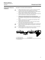
If the sensor is installed in a high-voltage environment and a fault condition or
installation error occurs, the sensor leads and transmitter terminals could
carry lethal voltages. Use extreme caution when making contact with the
leads and terminals.
NOTE
Do not apply high voltage (e.g., ac line voltage) to the transmitter terminals.
Abnormally high voltage can damage the unit. (Sensor and transmitter power
terminals are rated to 42.4 Vdc. A constant 42.4 volts across the sensor
terminals may damage the unit.)
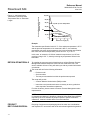
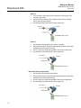
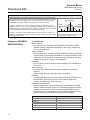
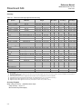
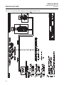
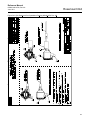
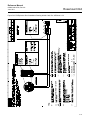
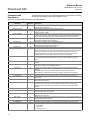
The transmitters will accept inputs from a variety of RTD and thermocouple
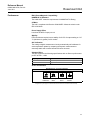
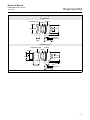
types. Refer to Figure 2-5 on page 2-7 when making sensor connections.
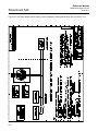
Refer to Figure 2-6 on page 2-8 for FOUNDATION fieldbus installations.
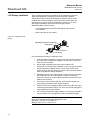
Use the following steps to wire the power and sensor to the transmitter:
1.
Remove the terminal block cover (if applicable).
2.
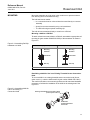
Connect the positive power lead to the “+” terminal. Connect the
negative power lead to the “–” terminal (see Figure 2-7).
3.
Tighten the terminal screws. When tightening the sensor and power
wires, the max torque is 6-in.-lbs (0.7 N-m).
4.
Reattach and tighten the cover (if applicable).
5.
Apply power (see “Power Supply”).
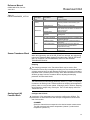
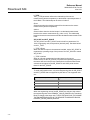
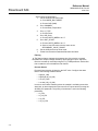
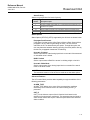
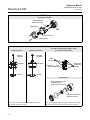
Figure 2-5. Transmitter Power,
Communication, and Sensor
Terminals
644H
Sensor
Terminals
Communication
Terminals
1
2
3
4
Power Terminals
2-7