1
ENGLISH
ESD-380
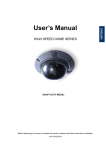
User’s Manual
HEAVY DUTY MODEL
Before attempting to connect or operate this product, please read these instructions completely.
CONTENTS
PREFACE....................................................................................................................2
FEATURES..................................................................................................................3
PRECAUTIONS...........................................................................................................5
QUICK STARTING ......................................................................................................6
FUNCTION DEFINITION ........................................................................................ 6
QUICK START FROM ESD-CC1 KEYBOARD ...................................................... 7
SWITCH SETTING ......................................................................................................9
SWITCH DEFINITION............................................................................................. 9
ID Setting ............................................................................................................... 9
Dome Control Protocol ....................................................................................... 10
RS-485 Setting..................................................................................................... 10
INSTALLATION .........................................................................................................12
CONNECTION...........................................................................................................17
CABLE CONNECTION......................................................................................... 17
22-PIN CONNECTOR DEFINITION...................................................................... 17
RS-485 Connector ............................................................................................... 18
OSD DISPLAY FORMAT...........................................................................................19
OSD DISPLAY FORMAT ...................................................................................... 19
SPECIFICATIONS .....................................................................................................20
SYSTEM ARCHITECTURE .......................................................................................21
SYSTEM ARCHITECTURE .................................................................................. 21
APPENDIX - OSD MENU ..........................................................................................22
OSD TREE STRUCTURE..................................................................................... 22
OSD MENU........................................................................................................... 25
MENU ITEM ...................................................................................................... 25
APPENDIX - PELCO .................................................................................................32
SYMBOL DEFINITION.......................................................................................... 32
SPECIAL FUNCTION ........................................................................................... 32
USING “PELCO KB” CONTROL DOME CAMERA............................................. 32
APPENDIX - PHILIPS ALLEGIANT ..........................................................................34
SYMBOL DEFINITION.......................................................................................... 34
SPECIAL FUNCTION ........................................................................................... 34
USING “ALLEGIANT KB” CONTROL DOME CAMERAS .................................. 34
1
PREFACE
The speed dome is a new subcompact dome camera system designed to deliver
superb performance and durability with a pristine housing that looks good in any security
and surveillance installation.
This speed dome contains new generation advanced DSP color camera, with 22X
optical zoom multiply 12X digital magnifier (23X optical zoom with 12 digital magnifier are
selectable items), delivers the power of a 364X zoom (276X zoom) to make sure that the
finest details are captured. Continuous auto focus, back light compensation, auto iris
controls, IR cut filter removable, privacy mask functions (IR cut filter removable and
privacy mask functions are not included in 22X lens) are some of the salient features
incorporated to fit your needs.
High speed tilt and 360° endless rotation and auto flip function allows this speed dome
to be installed in the most demanding applications. RS-485 communication channel is
available for remote control purposes, 128 preset points can be programmed for precise
location of target areas, and you can also define multiple cruise routes for the camera to
operate automatically.
Home function allows the user to specify a preset position as the ‘home position’.
Dome camera can come back to home position when the user stops to move the camera
for a while.
Dependability and ultra high reliability are key factors in the speed dome design cycle.
Every speed dome is assembled with meticulous care and thorough testing at our ISO
9001 compliant factory. High performance, reliability, and reasonably pricing, this speed
dome is an ideal solution to your tough surveillance requirement.
2
FEATURES
CAMERA FEATURES
1. Optical performance:
(1). DR model: 23X optical zoom with 12X digital magnifier.
(2). S model: 22X optical zoom with 12X digital magnifier.
2. Continuous Auto-focus or manual focus
3. Minimum illumination:
(1). DR model: 23X lens: 0.01 lux
(0 lux: IR illuminator ON)
(2). S model: 22X lens: 1 lux
4. Advanced DSP camera provide:
(1) Auto white balance
(2) Back-light compensation
(3) Auto iris control
(5) IR-cut filters removable mechanism. (DR model only)
(6) Electronic shutter
5. Slow Shutter function enable dome to gain a brighter video output through shutter
speed control. (DR model only)
6. Title Display function enable dome to display a string for a view. The title will be
displayed on screen if you pass through the region what you saved before.
7. IR-Cut Filter Removable :
(1). DR model: 23X lens: Equipped
(2). S model: 22X lens: N/A
8. WDR
(1). DR model: 23X lens: Equipped
(2). S model: 22X lens: N/A
9. Privacy Mask
(1). DR model: 23X lens: Equipped
(2). S model: 22X lens: N/A
3
ROTARY BODY FEATURES
1. 5” compact, low profile color dome camera
2. 360° endless rotation
3. Pan speed up to 375° /sec
4. Tilt speed up to 300° /sec
5. Preset function enable user to record different 128 viewpoints what you want. You can
set Pan/ Tilt/ Zoom for every preset position.
6. Proportional Zoom enables Pan/ Tilt speed inverse proportional to zoom ratio. You
can track an object easily with this function.
7. Auto-Turn Around function allows user to keep tracking object even the object pass
through the bottom of camera. You needn’t rotate 180 degrees in pan direction to keep
observing the object. This function will do this for you quickly.
8. Auto-Pan function enable dome camera to scan a specific region repeatedly with user
defined speed. You can set start point, end point and scan speed to scan a specific
region. User can make dome camera to do continuously panning without limit through
setting the start point the same as end point
9. Sequence function enable dome camera to switch viewpoints between presets.
There are three parameters can be filled into sequence function. You can set “Preset
number”, “Dwell Time” and “Speed” for sequence line.
10. Cruise function enable dome camera to scan a user defined path. User can manipulate
dome camera with joystick to establish this path.
11. Home function enables the possibility to lock a viewpoint or a function. Home function
will go back to home position or functions (Auto-pan/ Sequence/ Cruise) when user
move the camera to other position and the time period is expired.
12. Auto Restoring function will record current position when user defined period of time
is reached. Dome will go to the position if the power of your installation site is recovery
after shutdown.
13. Remote V-Sync Adjustment function enable user to adjust the line lock signal
remotely. You can adjust the phase of line lock signal to synchronize the system from
keyboard.
14. D Protocol and P Protocol Supported from OSD. You can control our dome camera
easily from any keyboard of PELCO (Pelco Corporation).
15. VCL Telemetry Control Protocol Supported from OSD. You can control our dome
camera easily from system of DM (Dedicated Micros Corporation).
16. Remote control via RS-485
17. Build-in 4 alarm input connectors
18. On Screen Display for camera control
19. 24VAC power model for easy installation
20. Twist lock release from bracket for easy installation and servicing
4
PRECAUTIONS
1.
Handle the camera carefully
Do not abuse the camera. Avoid striking, shaking, etc. The camera could be damaged
by improper handing or storage.
2.
DO NOT disassemble the camera
To prevent electric shock, do not remove screws or covers. There are no user
serviceable parts inside. Ask a qualified service person for servicing.
3.
Do not operate the camera beyond the specified temperature, humidity or power
source ratings
Use the camera under conditions where temperature is between -30°C ~ 45°C (-22°F
~ 104°F), and humidity is below 90%.
4.
Do not use strong or abrasive detergents when cleaning the camera body
Use a dry cloth to clean the camera when dirty. In case the dirt is hard to remove, use
a mild detergent and wipe gently.
5.
Never face the camera towards the sun
Do not aim the camera at bright objects. Whether the camera is in use or not, never
aim it at the sun or other extremely bright objects. Otherwise, blooming or smear may
be caused.
* PELCO is a registered trademark of PELCO Corporation.
* P protocol and D protocol are protocols what PELCO corporation used.
* DM is a registered trademark of Dedicated Micro Corporation.
5
QUICK STARTING
The section is a quick reference for users to manipulate a dome camera in a short
time. We explain the operational method through different keyboards.
FUNCTION DEFINITION
■ Preset Function Definition
Preset point means that dome camera will save pan/tilt/zoom positions to its memory.
You can recall the preset position through this function.
■ Auto-Pan Function Definition
Auto-Pan means that dome camera will scan a predicted region. The region is defined
by “start point”,”end point”, “scan direction” and “scan speed”.
Dome camera will scan a region from “start point” to “end point” according to the “scan
direction” and “scan speed”.
Dome camera will do pan motion continuously without limit if user set the start point the
same as end point.
You can manipulate zoom in/out function when the dome camera is executing
Auto-Pan function.
■ Sequence Function Definition
Sequence means that dome camera will switch its view between different preset
positions.
The sequence parameters are “preset point”, “jump speed” and “dwell time”.
Dome camera will switch its view according to the sequence parameters. It will go to
the “preset position N” with “jump speed S” and stay there for a period with “dwell time
T”. Then dome camera will go to the second preset position with the parameter 2….etc.
■ Cruise Function Definition
Cruise means that dome camera will patrol a special path. This path is generated by
joystick movement. The memory sizes of dome camera limit the length of cruise path.
After the memory of dome camera is filled up, it will stop to record the latter path. When
you recall cruise function, it will patrol the path which is stored in memory.
6
QUICK START FROM ESD-CC1 KEYBOARD
Please press <DOME> button and enter the ID of dome to start to control the selected
dome camera.
■ Preset Function Operation
■ Setting
Press a number key for preset point such as <2>. Press <SET PRESET> to
record this position as preset point 2.
■ Recall preset position
Press a number key for preset point such as <2>. Press <GO PRESET> to go to
the preset position 2.
■ Auto-Pan Function Operation
■ Setting
1. Press <AutoPan> to entering Auto-Pan mode. The LCD on keyboard will
display “1.RUN 2.SETTING”.
2. Press <2> to edit parameters of Auto-Pan.
3. Move dome camera to a specific position and press <ENTER> to save it as
start point of scan region.
4. Pan dome camera to another position and press <ENTER> to save it as
end point of scan region.
5. Using direction key to select the scan direction what you want. Press
<ENTER> to confirm this selection.
6. Using direction key to select speed of Auto-Pan. Press <ENTER> to confirm
this selection.
■ Execute Auto-Pan function
1. Press <AutoPan> to entering Auto-Pan mode. The LCD on keyboard will
display “1.RUN 2.SETTING”.
2. Press <1> to execute Auto-Pan function.
■ Sequence Function Operation
■ Setting
7
1. Press a number key to set a sequence line such as <1>. Press <SET
SEQ.> to start modifying parameters of sequence 1.
2. LCD is displaying “001. PST SPD DWELL” now. You can edit the
parameters such as <4> <ENTER> for PST, <1> <5> <ENTER> for SPD
and <5> <ENTER> for DWELL. That means that the first preset point for
sequence 1 is preset point 4, dome camera will staying 5 seconds there and
dome will go to next preset with speed 15.
3. LCD is displaying “002.PST SPD DWELL” now. Please edit the parameters.
4. LCD is displaying “003.PST SPD DWELL” now. Please press <SETUP> to
end the session if you need two presets only.
■ Execute sequence function
1. Press a number key to specify a sequence number what you want to
execution.
2. Press <RUN SEQ.> to start sequence function.
■ Cruise Function Operation
■ Setting
1. Press <CRUISE> key on keyboard to select execution mode of cruise
function.
2. LCD is displaying “1. RUN
2.SETTING” now. Press <2> to enter
modification mode.
3. LCD is displaying “ENTER for START POS”. Press <ENTER> to start to
input cruise path.
4. LCD is displaying “ENTER for END POS”. You can move dome camera to
patrol a path. Press <ENTER>
5. LCD is displaying “ENTER for SAVING”. Press <ENTER> to command
dome camera recording this cruise path.
■ Execute cruise function
1. Press <CRUISE> key on keyboard to select execution mode of Cruise
function.
2. LCD is displaying “1. RUN 2.SETTING” now. Press <1> to start cruise
function.
8
SWITCH SETTING
SWITCH DEFINITION
A
B
C
A. ID Setting (SW1~SW3)
B. Dome Control Protocol
C. RS-485 Setting
ID Setting
Use SW1 ~ SW3 to change your speed dome ID by turning the arrow to the desired
number respectively.
9
Dome Control Protocol
Refer to below table and turn the arrow to choose a protocol for your speed
dome.
SW No.
00
01
02
03
04
05
Protocol
VCL
Pelco D
Pelco P
None
Chiper
Philips
SW No.
06
07
08
09
10
11
Protocol
None
ELMO
AD 422
DS2P Pelco P
None
Simplex DSCP
SW No.
12
13
14
15
Protocol
None
None
None
None
RS-485 Setting
Refer to below table for desired RS-485 settings of your dome camera.
RS-485 Communication
Half-duplex
`
Full-duplex *
*Pin 3: Termination (OFF for Default Setting)
Pin 4: Line Lock (OFF for Default Setting)
Pin 5: Simplex
(OFF for Default Setting)
10
Alarm Pin Definition
11
INSTALLATION
STEP 1:
Unpack the dome package and take out the
dome bodies.
STEP 2:
Rotate the top holder and take it off from
the upper dome body.
STEP 3:
Rotate the smoke bubble and remove it.
12
STEP 4:
Now install the dome cover to protect the
camera lens.
Before actually doing that, apply some
lubricant on all surface of water-proof
rubber on the upper dome body to make
the installation process smoother.
Note that the tiny protrusion on upper
dome body must match to one of the four
holes on lower dome body.
Gently pressure the upper dome body
downward with two hands on the side of
the cover.
DO NOT press the cover as shown in the
picture on the right hand side; this might
cause the damage on the dome body.
13
STEP 5:
Screw the two dome bodies together. It
should be done if the lower dome body
looked swelled.
STEP 6:
If needed, assemble the sunshield for
outdoor use.
STEP 7:
Fix the sunshield to the dome with three
screws.
STEP 8:
Connect the attached RS-485, power and
BNC cables with your arranged cables.
14
STEP 9:
Put the cables through the gooseneck and
top holder.
the
STEP 10:
Mount the top holder to the gooseneck and
rotate the top holder clockwise.
STEP 11:
Then connect the cables to the dome body.
15
STEP 12:
Mount and screw the dome to the top holder.
Put on the rubber lastly.
Completion:
ESD-380
ESD-380 with sunshield
16
CONNECTION
CABLE CONNECTION
22-PIN CONNECTOR DEFINITION
The definitions of the pins on the 22-pin connector are listed as below table.
No.
1
2
3
4
5
6
7
8
9
10
11-20
21
22
Pin
AC24-1
Empty
AC24-2
Empty
FG
Empty
T+
RTR+
Empty
VGND
Video
Color
White
Black
Cable
1007 20AWG
Green
Yellow
Orange
Green
Brown
1007 24AWG
17
RS-485 Connector
Please connect keyboard to Speed Dome through the terminal block. The communication
interface between Speed Dome and Keyboard is RS-485. Maximum cable length for
RS-485 communication over 24-gauge wire is 4000 feet (1219 meters). The recommended
cable for RS-485 communication is CAT 5 cable.
Definition
T+ (D+)
R- (D-)
T- (D-)
R+ (D+)
Cable Color
Yellow
Orange
Green
Brown
18
OSD DISPLAY FORMAT
OSD DISPLAY FORMAT
1
3
2
4
6
5
< Fig1. OSD DISPLAY POSITION>
POSITION
FUNCTION
OSD DISPLAY
DESCRIPTION
1
FOCUS MODES
A
Auto Focus Mode
M
Manual Focus Mode
2
BACKLIGHT
X
Back Light Compensation OFF
B
Back Light Compensation ON
3
ALARM
ALARM
Alarm Message
4
ZOOM RATIO
X1
Present Zoom Ratio
5
TITLE
6
CAMERA ID
1. Max. 20 letters for each title.
2. 16 sets of titles are available.
Show the camera ID of this camera
19
SPECIFICATIONS
GENERAL FEATURES
ROTARY BODY FEATURES
Environment
Indoor / Outdoor
Controller I/F
Operating
Temperature
RS-485
Pan Travel
ESD-380
360 Degree
Endless
-30° – 45 °C
Tilt Travel
-99 ~ 99 Degree
Power Source
Max Power
Consumption
24 VAC
52W
w/o Sunshield: 234 x 305mm
Dimensions
w/ Sunshield: 263 x 305mm
Weight
Manual Speed
Preset
Speed
5.8kg
1~90 Deg/s
Pan
1~375 Deg/s
High Resolution
Tilt
6~360 Deg/s
Standard
Standard: 768 steps/circle High Res.: 1600 steps/circle
CAMERA FEATURES
CONTROL FEATURES
Camera
Environment
Module Type
ESD-380
S
DR
ESD-380S
ESD-380DR
D&P protocol
YES
YES
Presets
128
128
0.5
0.5
Patterns
1
1
Scanning Area
NTSC
NTSC
811(H)X 508(V)
758(H)X 504(V)
PAL
PAL
795(H)X 596(V)
758(H)X 592(V)
NTSC
NTSC
768(H)X 494(V)
724(H)X 494(V)
PAL
PAL
752(H)X 582(V)
724(H)X 582(V)
1/4" CCD
Sequence
4
4
Scanning system
PAL , NTSC , 2:1 interlace
Auto-Pan
1
1
Synchronization
Internal / Line Lock
Masking
X
8
Video Output
1.0Vpp/75 Ω , BNC
YES
YES
Horizontal
NTSC:470 TV lines. NTSC:470 TV lines
YES
YES
YES
YES
Module Type
Preset
Accuracy
Proportional
Pan & Tilt
Zone Title
Home
Function
P/T/Z
Auto-restoring
Auto-Turn
Total Pixels
Effective Pixels
Resolution
PAL:460 TV lines.
PAL:470TV lines
S/N Ratio
50dB
50dB
Minimum
Illumination
YES
YES
0.01 lux
1 lux
0 lux (IR illuminator)
Focal length
4~88 mm
3.6~82.8 mm
Zoom ratio
22x optical zoom
23x optical zoom
Digital Zoom
X1 ,X12 variable
X1 ,X12 variable
Zoom Speed
3.9 sec / 6.3 sec
2.9 sec / 5.8 sec
YES
YES
Digital Flip
X
YES
Focus Mode
Auto / Manual
DSS
X
YES
White Balance
Auto / Manual
IR
X
YES
Iris Control
Auto / Manual
WDR
X
YES
X
X
Around
Motion
Detection
Electronic
shutter
BLC
20
NTSC
NTSC
(1/60~1/30k sec)
(1/2~1/30k sec)
PAL
PAL
(1/50~1/30k sec) (1/1.5~1/30k sec)
On/Off
SYSTEM ARCHITECTURE
SYSTEM ARCHITECTURE
21
APPENDIX - OSD MENU
This camera utilizes a user setup menu that is displayed on-screen. This setup menu
contains various sub menus that from a tree-type structure as shown below. This menu is
described in the “SETUP MENU DESCRIPTION”
OSD TREE STRUCTURE
ON
OFF
BACKLIGHT ON
OFF
FOCUS
AUTO
MANUAL
APERTURE AUTO
MANUAL
DEFAULT
AE MODE
AUTO
SHUTTER
IRIS
AGC
WBC MODE AUTO
MANUAL
ID DISPLAY ON
OFF
SETUP
ENTER
MENU
BLC LEVEL
000 ~ 100
Focus Length: 1cm 10cm 30cm 1m
H APERTURE
000 ~ 031
V APERTURE
000 ~ 031
IRIS OFFSET
000 ~ 100
SHUTTER SPEED
IRIS
AGC
R GAIN
G GAIN
FLIP
IMAGE
ME
OFF
ZOOM SPEED
FAST
SLOW
SPEED BY ZOOM ON
OFF
AUTO CALI.
ON
OFF
DIGITAL ZOOM
1~12 (S model)
1~12 (DR model)
SLOW SHUTTER
1/2~1/60 (NTSC)
1/1.5~1/50 (PAL)
ANGLE ADJUSTER ADJUST MIN ANGLE
ADJUST MAX ANGLE
RESET
RESET
YES
EXIT
22
TITLE
DISPLAY
TITLE
SETTING
ALARM
SETTING
ON
OFF
000 ~ 016
HOME
SETTING
ENTER
ENTER
SEQUENCE ENTER
AUTOPAN
ENTER
CRUISE
ENTER
ALARM PIN
ALARM SWITCH
1~4
OFF
ON
ALARM TYPE
N.O.
N.C.
ALARM ACTION POINT
SEQUENCE POINT
PRESET POS
001 ~ 128
SEQUENCE LINE 1 ~ 4
DWELL TIME
001~ALWAYS SEC.
EXIT
YES
HOME FUNC.
ON / OFF
SELECT MODE
PRESET
SEQUENCE
AUTO-PAN
CRUISE
RETURN TIME
1 ~ 127 MIN.
PRESET/
AUTOPAN/
SEQUENCE/
CRUISE
GO
ENTER
EXIT
SEQUENCE LINE. 1 ~ 4
SEQUENCE
1 ~ 32
POINT
PRESET POS.
1 ~ 128
SPEED
1 ~ 15
DWELL TIME
1 ~ 127
RUN SEQUENCE ENTER
EXIT
START POINT
TO FIND
TO SAVE
END POINT
TO FIND
TO SAVE
DIRECTION
RIGHT
LEFT
SPEED
1~4
RUN AUTOPAN
ENTER
EXIT
RECORD START ENTER
RECORD END
ENTER
RUN CRUISE
ENTER
EXIT
23
IR
FUNCTION
WDR
SETTING
AUTO
THRESHOLD
IR COLOR
EXIT
ON
NONE (22X )
ENTER
WDR SWITCH
WDR FUNCTION
LOW. MID. HI.
B/W. COLOR
ON/OFF
AUTO
MANUAL
EXIT
PRIVACY
EXIT OSD
NONE (22X )
ENTER
PRIVACY SWITCH
SHADE
SET MASK
RESET
EXIT
NONE (22X )
YES
OFF / ON
GRAY / WHITE /BLACK
1/2
YES
YES
24
OSD MENU
There are two pages of OSD setup menu allow users to control the camera
parameters, these functions are described in the following sections in detail. Please use
LEFT/ RIGHT/ UP/ DOWN of direction keys to select your parameters.
MENU ITEM
1. DEFAULT
If you select ON for this item, all the camera parameters will be restored to the factory
initial (default) data. Once you modify any of the following items, this item becomes
OFF.
2. BACKLIGHT
In case that excessive light is behind the center object, it is necessary to prevent the
center object too dark.
Turn this item ON, the center object will be brighten in contrast to the edge of the picture
(where a backlight would most likely be located).
3. FOCUS
The focus of the dome camera can be operated in two different modes: ‘Manual Focus
mode’ and ‘Auto Focus mode’.
Manual
Users can the move focus lens by pressing the “focus Near/Far button” on the control
keyboard.
Auto
The optimum focus is achieved by the internal digital circuit. User can limit the minimum
auto focus range through selecting a suitable item for some special condition.
4. APERTURE
You can edit the aperture setting of camera module.
AUTO
Camera will automatically assign a suitable aperture value for camera to achieve a
better image.
MANUAL
You can set aperture value with higher value to enhance the incident ray of camera.
5. AE MODE
Here you can select how the auto exposure function works, five options are available in
this item, they are explained in the following section:
AUTO
With this option, the camera’s Shutter, IRIS and AGC control circuits work together
automatically to compensate the light exposure of CCD sensor, in order to get
consistent video output level. IRIS OFF SET is used to set the level of IRIS variation.
SHUTTER
With this option, the SHUTTER priority is higher than IRIS and AGC circuit will
function automatically to get consistent exposure.
25
IRIS
With this option, the IRIS priority is higher than SHUTTER and AGC circuit will
function automatically to get consistent exposure. After the IRIS is selected manually,
the action of exposure compensation depends on the AGC circuit.
AGC
With this option, the AGC priority is higher than SHUTTER and IRIS circuit will
function automatically to get consistent exposure. After AGC is selected manually, the
action of exposure compensation depend on changing the IRIS of Lens
6. WBC MODE
You can select one of six White Balance Control modes as described follows:
AUTO
In this mode, white balance works within its color temperature range.
MANUAL
In this mode, you can control the Write Balance value manually, R gain and B gain
adjustable range from 0 to 100.
7. ID DISPLAY
You can display the ID of dome on monitor or not.
ON
Display the ID address of this dome.
OFF
Do not display the ID address of this dome.
8. SETUP
You can adjust some parameters under SETUP item.
FLIP (IMAGE/ ME/OFF)
User can track an object continuously when it passes through under dome camera
with setting flip item to IMAGE/ ME.
IMAGE item enable user to keep tracking object seamlessly through image flip
technology. ME item is a standard function which is the same as AUTO-FLIP function.
ZOOM SPEED
You can select a suitable zoom speed.
SPEED BY ZOOM
The tracking speed is adjusted by internal algorithm. The lager zoom ratio the lower
rotation speed.
AUTO CALI.
The default setting is OFF.
DIGITAL ZOOM
Digital zoom ratio is adjustable from 1 to 12.
26
SLOW SHUTTER
You can set the slowest shutter speed. With the slowest shutter speed, you can see
objects in a dark environment under 0.2 lux. With a higher shutter speed, you can see
a smooth video image from camera
ANGLE ADJUSTER (MIN/ MAX)
User can see more area higher if they adjust the MAX angle to +99 degree. User can
see more area lower if they set the MIN angle to -10 degree.
RESET
Reset the Speed Dome.
EXIT
Exit the SETUP menu.
9. TITLE DISPLAY
You can turn on or off the TITLE DISPLAY function of this dome
ON
It will display a mark what you input for this view when you came back to the view.
OFF
It will not display any mark what you input for this view when you came back to the
view.
10. TITLE SETTING
You can name a view for dome camera and it will display the name when you came
back to the view.
STEP 1: Operate dome to a view what you want to name it.
STEP 2: Turn on OSD and move blink words to “TITLE SETTING”
STEP 3: Select a number what you want to name it.
STEP 4: Press <ENTER> to go into edit mode.
SET TITLE: (XXX)
0
1
2
3
4
01 2 3456 7 89
ABC DEFGH I J
K L MNOT P QR S
UV XYZ : / . ,
+ ? -
S : SAVE
S : EX I T
: LE FT
: R IGHT
TITLE:
X
STEP 5: Choose a character what you want to input with direction key and press
<ENTER>.
Example: A <ENTER>, B <ENTER>, C <ENTER>
TITLE: ABC
STEP 6: Move blink character to “S: SAVE” and press <ENTER> to save setting.
You can erase the word what you don’t like it through move blink character
27
to “SP” and press <ENTER>
11. ALARM SETTING
Alarm parameters can be set on this page.
ALARM PIN
Choose an alarm connector what you want to set its status.
ALARM SWITCH
Turn ON/ OFF alarm function.
ALARM TYPE
There are two kind of alarm types can be selected. One is normal open the other is
normal close.
ALARM ACTION
User can choose what kind of action should be executed when the alarm condition
taken place. There are two kind of alarm actions can be set. One is go to a specific
position when alarm taken place. The other is executing sequence function when
alarm condition taken place.
Point Mode
PRESET POS.
Enter a preset position where the dome will go to when alarm pin is triggered.
Sequence Mode
SEQUENCE
Enter the sequence line you wish the Dome execute when alarm pin is
triggered.
DWELL TIME (Seconds)
Camera will stay at the preset position for “DWELL TIME” seconds then go back to
previous position. If you select “Always”, dome will go to the preset position and stay
there until alarm condition is released or user move its joystick on keyboard.
EXIT
Quit the ALARM SETTING menu.
12. HOME SETTING
Home parameters can be set on this page.
HOME FUNC
Turn home function on or off.
SELECT MODE (AUTOPAN/ SEQUENCE/ CRUISE/ PRESET)
Dome will go to execute this mode function when home function is enabled and the
“RETURN TIME” is reached.
RETURN TIME (MINUTES)
Dome will start to count “RETURN TIME” when user move the camera to arbitrary
position.
AUTOPAN/ SEQUENCE LINE/ CRUISE/ PRESET POS
28
This item is detailed mode setting of home function. This item will vary with ‘SELECT
MODE’ item.
GO.
Go to execute home function (HOME FUNC ON only).
EXIT
Exit the HOME SETTING menu.
13. SEQUENCE
Sequence parameters can be set on this page.
SEQUENCE LINE
There are four sets of sequence lines built in dome camera. You can choose a line to
execute. Please use LEFT/ RIGHT of direction key to select your sequence line.
SEQUENCE POINT
There are 32 sets of sequence points can be specified in every sequence line. The
sequence points are linked list. Sequence function will go through the linked list
again and again.
PRESET POSITION
You can specify a preset position where the dome should go to at this sequence
point.
SPEED
Speed is adjustable from 1~15.
DWELL TIME
Dome will stay on the sequence point for “DWELL TIME” then go to next sequence
point.
RUN SEQUENCE
User can command dome camera to execute sequence function.
EXIT
Exit the SEQUENCE menu.
14. AUTOPAN
AutoPan parameters can be set on this page. User can enable dome camera to do
continuously panning without limit through setting the start point the same as endpoint.
START POINT
Start position of the “AUTOPAN path”.
TO FIND: Press ‘ENTER’ to go into joystick mode. User can move camera to
suitable position under joystick mode.
TO SAVE: Press ‘ENTER’ to set this position as start point and escape joystick
mode.
END POINT
End position of the “AUTOPAN path”.
TO FIND: Press ‘ENTER’ to go into joystick mode. User can move camera to
suitable position under joystick mode.
29
TO SAVE: Press ‘ENTER’ to set this position as end point and escape joystick
mode.
DIRECTION
Rotational direction of dome camera.
SPEED
AUTOPAN function will rotate camera with this speed.
RUN AUTOPAN
Execute AUTOPAN function.
EXIT
Quit the AUTOPAN menu.
15.
CRUISE
Cruise parameters can be set on this page.
RECORD START
Command dome to start to record “CRUISE PATH”.
STEP1: Press ‘ENTER’ to go into joystick mode. Dome will move blink words to
‘RECORD END’ automatically.
STEP2: User can move camera to form a path.
STEP3: Press ‘ENTER’ to save the path.
RECORD END
Command dome to stop to record “CRUISE PATH”.
RUN CRUISE
Execute “CRUISE” function.
EXIT
Quit the CRUISE menu.
16. IR FUNCTION
“IR Cut Filter” function can be set on this page.
AUTO
THRESHOLD: The Internal circuit will decide to remove the “IR Cut Filter”
according to its threshold value. You can set the sensitivity as high
then dome will remove the filter immediately if the threshold value
is reached. Of course, low sensitivity can improve the reliability of
lens.
IR COLOR:
You can program the video output as color or B/W when IR
function is enabled.
ON
Turn on IR function.
17. WDR SETTING
The parameter of WDR (Wide Dynamic Range) function can be set on this page.
WDR SWITCH
You can turn on/off the WDR function.
30
WDR FUNCTION
You can edit all parameters of WDR by yourself.
EXIT
Exit this page.
18. PRIVACY
You can program the privacy zone position with this option.
PRIVACY SWITCH
You can display “Privacy masks” with this option.
SHADE
The color of privacy mask can be selected through this option.
SET MASK
After you press “ENTER” on this item, dome will memory this position as “privacy
mask position”. You can select form Mask1 to Mask8 for this item.
MASK MENU
H CENTER 000~100
The original center of mask zone is the center of screen. User can move the
center of mask zone to another position through adjust this value.
V CENTER`000~100
The original center of mask zone is the center of screen. User can move the
center of mask zone to another position through adjust this value.
H SIZE 000~100
User can adjust the horizontal size of “privacy mask” through this item.
V SIZE 000~100
User can adjust the vertical size of “privacy mask” through this item.
EXIT+SAVE
Exit this page and save the privacy zone data into dome camera.
EXIT
Exit this page.
19. EXIT OSD
You can exit OSD mode with this item. Of course, you can close the OSD menu
through “ESC” button on ESD-CC1.
31
APPENDIX - PELCO
The Speeddome can be controlled through a keyboard which built in D protocol and
P protocol. Please follow the instruction to manipulate our Speeddome with a keyboard
which built in D protocol and P protocol.
SYMBOL DEFINITION
<Preset Go>
A single button which can command a dome to go to specific
preset position.
<Preset Set>
(1) A single button which can set preset parameter ( D
Protocol).
(2) A virtual button which is pressing <Preset Go> for 3
seconds to set preset parameter ( P Protocol ).
SPECIAL FUNCTION
7 7 <Preset Go>
(1) It can set display or close an OSD menu.
(2) It is a virtual key to emulate “ENTER” button.
7 8 <Preset Go>
Reset Dome Camera
USING “PELCO KB” CONTROL DOME CAMERA
1. Some differences between different keyboards when OSD is open.
■ P protocol keyboard can move cursor up/ down/ right/ left with pushing joystick up/
down/ right/ left.
■ D protocol keyboard can move cursor up/down with pushing joystick up/down. But D
protocol keyboard can move cursor right/ left with pushing joystick right/ left plus
press button on joystick.
2. Some differences for ‘ENTER’ command.
■ P/D protocol keyboard couldn’t issue ‘ENTER’ command directly. You can send a
‘ENTER’ command through “ 7 7 <Preset Go> “.
32
CABLE LENGTH
The communication interface between Speed Dome and Keyboard is RS-485.
Maximum cable length for RS-485 communication over 24-gauge wire is 4000 feet (1219
meters). CAT 5 cable is recommended.
CABLE DEFINITION (P Protocol Keyboard to Speed Dome)
Tx+ 8
Tx- 7
6
+ 12V 5
1 Tx+
2 + 12V
3 GND
GND 4
4 Rx+
5 Rx6 Tx-
Rx- 2
Rx+ 1
For P Protoc ol Ke yb oa rd
Fo r Sp ee d Dom e
CABLE DEFINITION (D Protocol Keyboard to Speed Dome)
Tx - 6
Tx+ 5
GND 4
1 Tx+
2
3 GND
GND 3
Rx- 2
Rx+ 1
4 Rx+
5 Rx6 Tx-
Fo r D Pro toc ol Ke yb oa rd
For Sp eed Dom e
33
APPENDIX - PHILIPS ALLEGIANT
The dome cameras can be integrated into Philips Allegiant systems through A
repeater.
Please follow the instructions to control dome cameras through Philips Allegiant
systems.
SYMBOL DEFINITION
<shot>
A physical single button :
Command dome cameras to go to specific preset position.
<set>
A physical single button :
Set preset position.
SPECIAL FUNCTION
7 6 <set>
1. Exit OSD menu direct
7 7 <set>
1. Open or close OSD menu.
2. Virtual key to send an “ENTER” command when OSD is
opened.
7 8 <set>
1. Reset Doma camera.
<Iris Open>
A physical single button :
Send an “ENTER” command when OSD is opened.
USING “ALLEGIANT KB” CONTROL DOME CAMERAS
1. Some differences between different keyboards when OSD is opened.
■ User can move cursor left/right/up/down through pushing joystick left /right/up/down.
2. Some differences for ‘ENTER’ command.
■ User cannot send ‘ENTER’ command directly. User can send a ‘ENTER’ command
through “ 7 7 <Set> “.
34
1478 Old Country Rd.
Plainview, NY 11803
www.elmousa.com
35