1
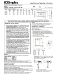
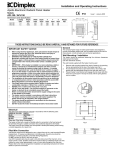
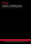
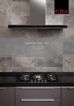
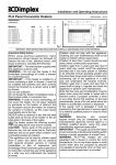
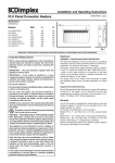
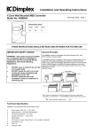
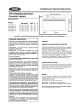
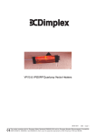
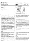
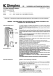
Installation and Operating Instructions
Electronic Panel Convector Heater
Models:
IP24
EVX050 / EVX075 / EVX100 / EVX125 / EVX150 / EVX200
EVS050 / EVS075 / EVS100 / EVS150
Issue 5 November 2004
Dimensions and Specification
Model
EVX050
EVX075
EVX100
EVX125
EVX150
EVX200
Loading
(kW)
0.5
0.75
1.0
1.25
1.5
2.0
Length (A)
(mm)
440
440
440
440
440
440
Height
(mm)
340
340
420
500
580
740
Depth
(mm)
107
107
107
107
107
107
X
(mm)
156
156
236
178
248
405
Y
(mm)
90
90
90
107
117
120
Z
(mm)
94
94
94
215
215
215
Weight
(kg)
3.5
3.5
4.2
4.8
5.4
6.6
EVS050
EVS075
EVS100
EVS150
0.5
0.75
1.0
1.5
580
820
1060
1300
220
220
220
220
107
107
107
107
186
426
666
906
149
149
149
149
245
245
245
245
3.4
4.6
5.7
6.9
THESE INSTRUCTIONS SHOULD BE READ CAREFULLY AND RETAINED FOR FUTURE REFERENCE
IMPORTANT SAFETY ADVICE
•
•
•
•
•
•
•
•
•
•
•
•
•
When using electrical appliances, basic precautions should always be
followed to reduce the risk of fire, electrical shock, and injury to
persons, including the following:
WARNING THE SURFACES OF THIS HEATER CAN BE HOT
Momentary contact with any part of the heater should not cause injury.
However, aged or infirm persons or young children should not be left
unsupervised in the vicinity of the heater unless a suitable guard is
fitted
IMPORTANT – If this heater is installed in a room containing a bath or
shower, it should be so installed that switches and other controls
cannot be touched by a person using a bath or shower – to comply
with this requirement see ‘Lock the Control Cover’ section on page 2.
If you use this heater in conjunction with an external thermal control, a
programme controller, a timer or any other device which switches the
heat on automatically, observe all safety warnings AT ALL TIMES since
a fire risk exists when the heater is accidentally covered or displaced
The installation of this product should be carried out by an electrician
or competent person and be in strict accordance with the current IEE
Wiring Regulations and relevant Building Regulations
This heater must not be mounted within 150mm of curtains and other
combustible materials or 100mm from a shelf or overhang
NEVER cover or obstruct in any way the heat outlet slots at the top of
the heater or the air inlet slots at the base of the heater
DO NOT cover the heater – Do not place material or garments on the
heater or obstruct the air circulation around the heater
Before connecting the heater check that the supply voltage is the same
as that stated on the heater
The heater must be installed in accordance with these instructions
The heater must be mounted using the wall bracket supplied. The
heater should only be operated in the upright position
The heater should be positioned in accordance to the clearances
stated in these instructions
General
The compact EVX and low profile EVS are designed to provide rapid
heat warm up in both domestic and commercial applications.
Wall Mounting / Installation
The heater should be positioned observing the minimum clearances
stated around the heater.
(see also ‘Electrical’ section)
EVX Range
The wall bracket supplied with the heater must be used
1.
2.
3.
Remove wall mounting bracket from back of heater by de pressing
the two spring latches at the top of the heater (see Fig.1)
Fix wall bracket securely to wall via the three or four holes in the
bracket with the appropriate fixings for the wall type (see Fig.2)
Present heater to wall bracket and engage the two lower slots first.
Then line up and push in the top two slots until the spring latches
click in to place
Fig.1
Fig.2
Model
EVX050
EVX075
EVX100
EVX125
EVX150
EVX200
DO NOT locate this heater immediately beneath a fixed socket outlet
Electrical
The wires in the mains lead are coloured in accordance with the following code:
GREEN & YELLOW EARTH
BLUE
NEUTRAL
BROWN
LIVE
BLACK
PILOT WIRE
(See also ‘Pilot Wire Connection’)
The heater is fitted with a length of flexible cable for connection to the fixed wiring of
the premises through a suitable connection box positioned adjacent to the heater.
The supply circuit to each heater must incorporate a double pole isolating switch having
a contact separation of at least 3mm
Pilot Wire Connection
The BLACK control wire is designed to carry a signal from slot in or wall mounted Dimplex
programmers. If, however a programmer is not being used, the pilot wire should be
isolated in accordance with the current IEE Wiring Regulations.
IMPORTANT - Do NOT connect the BLACK pilot wire to earth
Care should be taken with the installation of the pilot wire(s) as when switching to
background (set back) they become energised at 240V although only at a current of 1mA.
In every case a suitable means of isolation must be provided for the pilot wire and marked
to indicate that two sources of supply may be present at the heater.
Where pilot wires are installed separately from the heater final sub-circuit they should be
protected, double insulated and carry their own integral earth continuity conductor.
A (Width)
340
340
420
500
580
740
B (Bracket Width)
156
156
236
178
248
405
EVS Range (Fig.3)
1.
2.
3.
Mark the fixing positions for the top two screws on the wall
in accordance with the dimensions shown in the diagram
below, ensuring the two top fixing points are level
Fix the two screws to the wall and hang the heater through
the top two key hole slots
Finally, secure the heater with two more screws at the base
Fig.3
Operation
Advice on Using your Heater
•
•
•
•
For greatest economy switch the heater to background (setback) if you
leave the room for long periods of time or before going to bed.
The ideal level of setback is normally around -5ºC (16ºC room
temperature). Greater setback is not necessarily more economical
because of the amount of energy needed to bring the room temperature
back up to the comfort level.
Do not set the comfort level too high. Even small reductions on the
thermostat setting can save a lot of energy.
If you go away for a long period of time select the frost protection setting
on the function dial or reduce the thermostat setting to a lower level.
Locking the Thermostat Setting (C)
Mode Selection Dial (A)
Use this rotary dial to select the function you require
Symbol
Function
Description
Heater will switch on to provide frost
Frost Protection
protection if the room drops below
5ºC
Heater will maintain a lower
Background (set back)
temperature level for background
heating (comfort less 2ºC to 7ºC)
Comfort
Off
Heater will maintain the temperature
set on the thermostat dial
Off
Heater will not function
Programme
Heater will be controlled by a
programming device
If necessary you can lock the thermostat dial to a single setting or range.
To lock the settings, use a small pair of narrow nosed pliers to pull out the
locking pins at the rear of the thermostat dial.
The following settings can be obtained: (see Fig.4)
•
•
•
•
Single setting – Set thermostat dial to desired setting (eg no.6). Locate
one pin directly opposite the setting required
Minimum setting – Set thermostat dial to desired setting (e.g. no.6).
Locate one pin opposite the setting required and one hole to the left.
(The thermostat will now be adjustable from 6-9 only)
Maximum setting – Set thermostat dial to desired setting (eg
no.6).Locate one pin opposite the setting required and one hole to the
right. (The thermostat dial will now be adjustable from 1-6 only)
Minimum - maximum setting – (e.g. no.2-4) Locate both pins and
space apart until desired range is found
Note: If the programme function is selected but no programming device is being
used, the heater will function in comfort mode
The following Dimplex programmers are available:
Pilot Wire Wall Mounted Controller (2 Zone) – Part no. RX010006
MBS Wall Mounted Programmer (2 Zone) – Part no. RX010007
MBS Slot in Receiving Cassette – Part No. RX9913
MBS Slot in Programming Cassette (Single Zone) – Part no. RX9912
Pilot Wire Programming Cassette (Single Zone) – Part no. RX9911
Function Display (B)
Neon indicators adjacent to the function selector will light to show the mode
selected
Setting the Comfort Temperature (C)
Use the thermostat dial (C) to select your desired room temperature. The
Fig.4
To Lock the Control Cover (F)
A screw is provided to permanently lock the cover in position. It is located on
the back of the control box, under the thermostat dial. Remove this and
screw through the notch below the lifting tab into the plastic housing. (see
also Fig.4 above)
Safety
A thermal cut-out will switch off the heater if, for any reason, it overheats.
Should the cut-out operate, switch off the mains supply and allow the heater
to cool. Once the heater has cooled sufficiently remove the obstruction and
switch on the mains supply.
markings on the dial are in approximately 3.5ºC increments. The settings are
(Frost Protection) and numbers 1-9 (MAX). The quickest way to find your comfort
setting is to turn the thermostat dial to the maximum setting. When your ideal
Cleaning
comfort level is achieved, turn the thermostat dial down until the thermostat
Before cleaning your heater, switch off the heater and allow it to cool.
switches off (the neon light will go out) Leave at this setting and the heater will
Disconnect the electricity supply to the appliance. The outside can be
automatically maintain the desired temperature.
cleaned by wiping it over with a soft damp cloth and then dried. Do not use
abrasive cleaning powders or furniture polish, as this can damage the
Thermostat Light (D)
surface finish. To release the heater from the wall bracket for cleaning or
The neon indicator below the thermostat will light when the heater is operating.
redecoration, depress latch on both brackets and hinge forward (EVX
models only)
Background (set back) Setting (E)
This dial is marked in degrees from -2ºC to -7ºC.
This is the amount the room temperature will be allowed to drop when you switch
the function selector from comfort to background.
For example:
To drop the room temperature by 5ºC select -5ºC on the setback dial. If the room
temperature is normally 21ºC this will reduce to 16ºC when in background
(setback) mode.
Reverting to comfort mode will automatically cause the temperature to rise to the
setting on the thermostat dial.
After Sales Service
Your product is guaranteed for one year from the date of purchase.
Within this period, we undertake to repair or exchange this product free of
charge (excluding lamps & subject to availability) provided it has been
installed and operated in accordance with these instructions.
Your rights under this guarantee are additional to your statutory rights, which
in turn are not affected by this guarantee.
Should you require after sales service you should contact our customer
services help desk on 0870 727 0101. It would assist us if you can quote the
model number, series, date of purchase, and nature of the fault at the time of
your call. The customer services help desk will also be able to advise you
should you need to purchase any spares.
Please do not return a faulty product to us in the first instance as this may
result in loss or damage and delay in providing you with a satisfactory
service.
Please retain your receipt as proof of purchase.
This appliance complies with European Safety Standard EN 60335-2-30, and European Standards EN 55014, EN 60555-2 and EN60555-3 for Electromagnetic
Compatibility. These standards cover the requirements of the EEC Directives 73/23 and 89/336.
Glen Dimplex UK Ltd
Millbrook House
Grange Drive
Hedge End
Southampton
SO30 2DF
UK Customer Help Line (8am-6pm Mon-Fri; 8:30am-1pm Sat.)
Customer Services: Tel: (0870) 727 0101
Fax: (0870) 727 0102
E-mail:[email protected]
Web-site: www.dimplex.co.uk
Republic of Ireland
Tel: 01 842 4833