1
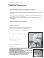
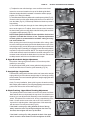
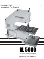
DL5000 INSTRUCTION MANUAL
DIAMOND TECH
Innovations For Creativity
DL 5000
DIAMOND LASER BAND SAW
OPERATIONS MANUAL
DL5000 INSTRUCTION MANUAL
- PAGE 1
Before You Begin
Read and follow all instructions carefully.
• After unpacking all components, assemble band saw on a firm level surface to prevent saw from tilting
and rocking.
• Be sure the power switch is in the OFF position before plugging in the band saw.
• Always disconnect band saw from electrical outlet before setting up or servicing.
• Wear proper apparel. Never wear loose fitting clothes, neckties, jewelry and gloves that may get caught in
moving parts.
• Remove all wrenches before using band saw. Leaving wrenches attached while operating this tool may
result in damage to the machine and/or operator.
• Always wear safety goggles. Everyday eyeglasses have only impact resistant lenses; they are not
safety glasses.
• Never turn on band saw while glass or working materials are touching the blade.
• Always hold material being cut firmly on cutting table.
• Feed materials at a slow easy pace into the blade. Avoid sudden twisting of the blade, which may cause
kinking or breaking.
• Keep out of reach of children.
• Never leave saw running unattended. Turn power OFF when not in use.
• Do not operate while under the influence of medication or alcohol.
• To ensure top performance keep band saw properly maintained.
Contents
Your Diamond Laser 5000™ has been shipped partially
assembled. Carefully remove saw and parts from the packaging.
1.
1-Band Saw Body
2-Cutting Table
3-Recirculating Water Pump and Valve
4-Detachable Water Reservoir
5-Straight Edge/Angle Cutting Guide
6-Adjusting Wrenches
6.
Assembly Instructions
5.
A. Table Installation
2.
1) Remove table mounting set screws and washers from
the table mounting block directly behind the blade (Fig.1).
Loosen and remove the table alignment screw and wingnut located on the
front of the cutting table blade slot (Fig.2).
2) While holding the table with the slot opening directly behind the blade,
carefully slide the diamond blade through the slot.
3) Secure cutting table to the mounting block with the table mounting set
screws. Return alignment screw to the front of the cutting table
and tighten in place with the wingnut positioned under table.
4.
3.
Fig.1
PAGE 2 -
DL5000 INSTRUCTION MANUAL
B. Blade Installation
Blade comes preinstalled; however should it become loose in
shipment or need to be replaced, follow these instructions.
1) Turn power OFF and unplug from electrical outlet. Open the band
saw cover by loosening the knobs on the front of the saw and
removing front panel.
2) Remove table alignment screw and wing nut.
3) Loosen blade tensioning knob, located at the top of the band
saw (Fig.3) until blade has give.
4) Pull downward on the upper blade wheel (Fig.4) and remove worn
blade. Install the new blade by centering it on the lower blade wheel
(Fig.5), then on the center wheel and finally on the upper wheel.
5) Ensure blade is centered and fits between the blade guides
located on the upper guide block and the lower block under the table.
(refer to section D - Band Saw Use and Maintenance: Blade
Guide Adjustment).
6) Tighten blade by turning blade tensioning knob clockwise (Fig.3)
(refer to section C - Band Saw Use and Maintenance: Blade
Tensioning).
7) If necessary, adjust table position to recenter blade in the
table opening.
Fig.2
Table Alignment Screw
Fig.3
Fig.4
WARNING: If the diamond blade is too loose, it can slip from the
wheels. If stretched too tight, it could break.
C. Water Systems
1) Place the water reservoir on a solid level work surface. Place
reservoir underneath the lip located on the right side of the saw
base (Fig.6).
2) Insert brass pump valve into the top of the recirculating water
pump. Place pump in the water reservoir (Fig.7).
3) Plug pump’s electrical connector into the outlet on the rear of the
saw (Fig.8).
5) Fill the reservoir with 2” of water before use
(Approximately 3 quarts).
6) To test pump, the saw must be turned ON. Be sure the blade has
been properly installed and there are no obstructions to interfere with
its operation and blade movement. DO NOT attempt to touch the
blade or blade wheels while the machine is turned ON.
7) Test pump and water flow by turning machine ON. The blade
should not be moving; be sure reostat is turned to “0”. Watch for
bubbles in the hose. Water should begin to flow freely from the water
nozzle mounted on the upper blade guide block assembly. To insure
water flow is directed at the front edge of the blade just below the
guide assembly, adjust position of water nozzle by loosening the set
screw (Fig.9).
8) If large pockets of air appear in the hose line, this may stop the
flow of water to the blade. If this occurs, prime the pump by tipping it
on its side and allow the intake to draw in air through the line. Then
return the intake grill into the water and watch for the water to fill the
line. Small air bubbles may persist in the line but these will not
interfere with sufficient flow to the blade.
WARNING: Never operate saw if there is insufficient water at the
point of cutting, as this will cause damage to the blade.
Fig.5
Fig.6
Fig.7
Fig.8
DL5000 INSTRUCTION MANUAL
- PAGE 3
Band Saw Use and Maintenance
A. Drive Belt Tension Adjustment
A loose drive belt may result in a noticeable loss of power to the
blade wheels.
1) To tighten the drive belt, turn saw OFF and unplug the saw from the
electrical outlet.
2) Remove all screws securing rear panel encasing the motor (Fig.10).
3) Loosen both motor mount set screws using a large hex
wrench (Fig.11).
4) Press the motor downward to desired belt tension and secure into
position by retightening the motor mount set screws. There should be
moderate give in the belt tension (1/4” flex top and bottom).
WARNING: Do not overtighten belt. Overtightening the drive belt will
slow the motor down and damage the motor. A loose belt will not
turn the blade wheels properly.
B. Drive Belt Replacement
1) To replace the drive belt, turn saw to OFF position and unplug from
the electrical outlet.
2) Remove all screws securing panel encasing the
motor (Fig. 11).
3) Remove left center screw holding the motor plate into position.
Loosen right motor mount screw slightly.
4) Pivot motor slightly to the right and drive belt will loosen (Fig.12).
Pull drive belt off the motor and pulley wheel.
5) Replace drive belt by first wrapping it around the motor pulley. Then
holding the belt over the pulley wheel, rotate it to the right, coaxing
the belt onto the pulley wheel from the bottom up (Fig.13).
6) Replace and tighten motor mount plate screws and adjust belt
tension as needed.
7) Replace the rear panel encasing the motor and fasten
with screws.
C. Blade Tension
A tension meter is located on the top back panel of the DL5000
(Fig.14). Proper tension is achieved when the gauge is just touching
the top of the “tight” red mark. You can check this by pushing on the
flat side of the blade between the upper wheel and upper guide and
you should get 1/4”-1/2” movement side to side. If you can not flex the
blade 1/4” - 1/2”, loosen until you can and use this meter reading as
the correct setting for this blade. Recheck with each new
blade replacement.
WARNING: If the diamond blade is too tight, breakage could occur.
During operation, the blade will begin to expand due to friction and
heat. If the blade begins to vibrate from side to side during operation,
tighten the tension knob again so the meter position remains the
same as it was originally set for this blade.
WARNING: When shutting off the machine after a day of operation,
loosen the blade tension. Before returning to operation again,
tighten the tension so the meter reads correctly for the blade in use.
D. Blade Guide Adjustment
The DL5000 comes with lower and upper blade guides. Proper
alignment of these guides are essential for proper cutting and
extending blade life.
Fig.9
Fig.10
Fig.11
Fig.12
Fig.13
Fig.14
PAGE 4 -
DL5000 INSTRUCTION MANUAL
1) To adjust the rear roller bearings, use a small hex wrench and
loosen the set screw located on the top of the blade guide block.
Slide the blade guide block backward or forward to achieve proper
position (1/16” away from blade).
2) The blade should fit directly between the small square guides (Fig.15),
located on the front of the upper blade guide block no more than 1/16”
from the blade (Fig.16). Guides help stabilize the blade to prevent it
from twisting.
3) The blade should pass through the lower blade guide block the
same as the upper set. To adjust, loosen the set screws located on
the lower blade guide mounting block and slide blade guide arm back
or forward to adjust properly (Fig.17).
NOTE: Blade guides and blade tension should be checked and
adjusted if needed after 3 hours of use. Frequent replacement
of blade guides is recommended to maintain cutting accuracy
and extend blade life.
When pushing the material through the blade while cutting, make
sure the round support bearing behind the blade does not spin. If the
roller begins to spin, back off the pressure of feeding the material until
the spinning stops. Eventually you will begin to know the exact pressure
required to cut specific materials. NOTE: The support bearing should
not be used as a back stop for the blade to increase cutting time. This
constant contact will wear the blade down from the back side as well
as add pressure and friction to the blade until it snaps.
Fig.15
Fig.17
Set
Screw
Fig.16
Upper
blade
guide
E. Upper Blade Guide Height Adjustment
The position of the upper guide should be 1/4” from the top of the
material you are cutting.
To adjust height of blade guide, loosen guide bar locking knob on
back of saw and raise or lower the guide assembly (Fig. 18).
F. Straight Edge / Angle Guide
The band saw is designed for intricate radius cuts, however the straight
edge guide will permit moderate straight edge or fixed angle cutting
when needed. Place work material against the straight edge guide and
feed the material
slowly. For easy installation, place guide in groove located on cutting
table. Adjust guide location by removing the adjusting screw and moving
guide to the various slots on the table top (Fig.19).
G. Blade Tracking - Upper Wheel Tracking Adjustment
The optimal position for the blade is to track in the center of all three
blade wheels but most importantly the top wheel. If the blade is not
centered, you can adjust the hub assembly screws behind the upper
wheel. This allows for the wheel to tilt, forcing a repositioning of the
blade. You will need to remove the rear cover of the machine to
expose the 6 adjusting bolts. Need photo here of hub assembly
with arrows to inner and outer bolts (Fig.20).
Fig.18
Locking
Knob
Fig.19
Inner Top
Outer Top
Fig.20
If the blade is coming off or riding towards the front of the top
wheel, loosen the Inner Top Hex Bolt and tighten the Outer Top
Hex Bolt, then retighten the Inner Top Hex Bolt.
If the blade is coming off or riding towards the back of the upper
wheel, loosen the Inner Bottom Hex Bolt and tighten the Outer
Inner Bottom
Outer Bottom
DL5000 INSTRUCTION MANUAL
- PAGE 5
Bottom Hex Bolt, then retighten the Inner Bottom Hex Bolt. After
adjusting, manually turn the wheels to ensure proper blade tracking.
Quick Tips
1) When cutting, the highest blade speed will usually result in efficient and
smooth cutting. Use a slower speed when working with delicate materials
or making very tight turning radius.
2) Do not force materials into the blade. Ease the materials into the blade,
turning as you go to create your pattern. Keep a constant forward
movement of the material through the blade as you make your curves.
Avoid twisting the blade on tight curves.
3) To back out of a cut, turn the saw off and ease the material away from
the blade.
4) Clean band saw after each use with water. Run clean water through
pump until it runs clear and the water tube appears clean. Frequent use of
WD40 or similar lubricant on all screws and moving parts is recommended.
5) When not in use, loosen blade wheel tension. When storing for
extended periods, remove blade and drive belt, then store.
6) Use a waterproof pen to mark your pattern on material. For added
protection, use Chap Stick™ or candle wax over line before cutting.
7) Two or more pieces may be cut at the same time by stacking them
together and using “tacky wax”, rubber cement or double-sided tape to
hold material in place. If using glue or tape, clean blade after use by
running a clean piece of glass or tile through blade. It is not recommended
that you cut through thickness greater than 3/4”.
PAGE 6 -
DL5000 INSTRUCTION MANUAL
Troubleshooting
Problem: Blade jammed in work material.
Cause:
Twisted blade from forcing work materials into the blade.
Solution: Before freeing any jammed materials, immediately turn OFF power switch and wait until all moving
parts have stopped. Gently free work material, holding blade against the blade guides to prevent it from stretching
or badly twisting. Back out of the cut if needed. Inspect blade for kinks and ensure there is no remaining debris
in the blade path which may have caused the jam.
Problem: Saw runs slowly or stops while cutting
Cause:
Drive belt slippage or broken.
Solution: See Band Saw Use and Maintenance Drive Belt Tension-Section A.
Additional Parts
Item
DL5000 TABLE
DL5000 MAIN FRAME
DL5000 VARIABLE SPEED CONTROL 110V/220V
DL5000 WHEEL SET
DL5000 DRIVE BELT
DL5000 UPPER BLADE BLOCK
DL5000 LOWER BLADE BLOCK
DL5000 DRIVE HUB ASSEMBLY
DL5000 NON-DRIVE HUB ASSEMBLY
DL5000 STAINLESS STEEL BLADE - TILE
DL5000 STAINLESS STEEL BLADE - GLASS
DL5000 BLADE GUIDE SET
Item Number
P500
P501
P502/P502A
P503
P540
P542
P543
P544D
P544ND
16
47
34
Blade Repair Service
Diamond Tech offers a blade repair service should a blade break with ample diamond remaining. Return
blade, indicating saw model and payment to Diamond Tech, Blade Repair Service, 5600 Airport Blvd.,
Suite C,Tampa, FL 33634. For International and special handling, please include extra postage and
shipping instructions
Blade Repair Fees (U.S. Dollars):
Speedster, DL1000, DL3000........................................................................ $25.00
DL5000......................................................................................................$45.00
DL7000......................................................................................................$78.00
DL5000 INSTRUCTION MANUAL
Diamond Tech
Diamond Laser 5000 1 Year Warranty
All Diamond Laser 5000 Band Saw and accessories are manufactured to high quality standards
and are serviced by highly qualified technicians.
Diamond Laser 5000 Band Saw is warranted to the original purchaser for one full year from
the original purchase date. During the one year period, if you feel the Diamond Laser 5000
Band Saw is not performing properly and needs to be serviced, contact Diamond Tech at 800937-9593 or email [email protected] for a Return Authorization Number. Equipment will not
be accepted at Diamond Tech without a Return Authorization Number.
If returning the Band Saw for evaluation or repair, be sure to include your Name, Address,
Daytime Phone Number with Area Code and a letter explaining the specific problem you are
encountering. You will be contacted if any necessary parts or service are not covered under
the warranty.
Date of purchase ___ / ___ / ___
Mark the Return Authorization Number clearly on every package! Do not send this product back
without such prior authorization! Return postage and insurance are the responsibility of the
consumer. Diamond Tech will return your equipment postage paid and insured if it is under
warranty. Any Band Saw no longer under warranty will be returned at the owner’s expense.
Diamond Tech reserves the right to repair or replace faulty equipment at its discretion. The
Diamond Laser 5000 Band Saw is warranted against defective materials or workmanship. If the
Diamond Laser 5000 Band Saw suffers damage due to customer modifications and/or is used
for any application other than that for which it was designed, this warranty is void. This warranty
does not include damage due to: (A) neglect (B) accident (C) unreasonable use (D) improper
maintenance (E) any other causes not attributed to defects in material or workmanship. This
warranty specifically excludes the Diamond Laser 5000 Band Saw blades and/or guides. Any
implied or otherwise explicit guarantees made through merchandiser of this product are not
covered in this warranty coverage agreement and are expressly disclaimed.
IMPORTANT NOTE: This machine was designed for certain applications only. Diamond Tech
strongly recommends that this machine NOT be modified and/or used for any application other
than that for which it was designed. If you have any questions relative to its application, please
contact us and we will advise as to it proper use.
Diamond Tech, USA
5600 Airport Blvd., Suite C, Tampa, Florida 33634
Tech Support: 800-937-9593 (U.S.A., Canada) 813-806-2923 (International)
Fax: 813-806-1988, Email: [email protected]
www. DiamondSaws.com
4/2007