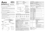
1
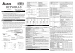
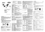
1. Status indicator (Power, RUN and ERROR)
2. Model name
3. DIN rail clip
4. I/O terminals
5. I/O point indicator
6. Mounting hole of the expansion unit
7. Nameplate
http://www.delta.com.tw/products/plc.asp
DVP02DA-S
DVP02DA-S
Analog Output Module
2.3
WARNING
*2
Make sure that DVP02DA-S is properly grounded
2
2.1
Voltage output
0V ~ 10V
CH1
V+
COM
Isolation wire *1
FG
Current output
0mA~20mA
CH2
V+
I+
CH2
FG
Isolation wire *1
terminal of
power module
*3
DC24V
System
Grounding
power module
Note 3: Please connect
COM
DC/DC
24+
24-
converter
+15V
AG
-15V
analog output module
terminal and
terminal to system earth point and make
system earth point be grounded or
connects to machine cover.
Warning: DO NOT wire to the No function terminal
Class 3 Grounding
(100 Ω or less)
2.4
Terminal of analog module layout
DVP04AD-S
DVP02DA-S
V+
I+
COM
FG
V+
I+
COM
FG
, to avoid any electromagnetic noise.
DVP04DA-S
V+
I+
COM
FG
V+
I+
COM
FG
V+
I+
COM
FG
V+
I+
COM
FG
INTRODUCTION
Model Explanation and Peripherals
DVP04PT-S
DVP04TC-S
V+
I+
COM
FG
V+
I+
COM
FG
L+
LIFG
L+
LIFG
L+
LSLD
V+
I+
COM
FG
V+
I+
COM
FG
L+
LIFG
L+
LIFG
L+
LSLD
DVP06XA-S
DVP08RT-S
V+
I+
COM
V+
I+
COM
V+
I+
COM
V+
I+
COM
V+
I+
COM
V+
I+
COM
L+
LSLD
L+
LSLD
L1+
L1L2+
L2L3+
L3L4+
L4FG
L51
L5L6+
L6L7+
L7L8+
L8FG
Thank you for choosing DELTA DVP PLC Series. The analog output module of DVP02DA-S series
can read/write the data of analog output module by using commands FROM / TO via DVP-PLC
SS/SA/SX Series MPU program. The analog output module receives 2 group 12-bit digital data
from PLC MPU and converts it into 2 points analog output signal (voltage or current). There are 49
CR (Control Register) in each module and there are 16 bits in each register.
3.1
The software version of DVP02DA-S analog output module can be updated via RS-485
STANDARD SPECIFICATIONS
Specifications
Digital/Analog (2D/A) Module
Voltage Output
Current Output
communication. Power unit and module are separate. Size is small and easy to install.
Power Supply Voltage
24 VDC (20.4VDC~28.8VDC) (–15%~+20%)
Users can select output either voltage or current via wiring. Voltage output range is 0V ~ +10V DC
Analog Input Channel
2 channels / each module
(resolution is 2.5 mV). Current output range is 0mA ~ 20mA (resolution is 5 µA).
Analog Output Range
0~10V
0~20mA
Nameplate Explanation
Digital Data Range
0~4000
0~4000
Resolution
12 bits (1LSB=2.5 mV)
12 bits (1LSB=5 µA)
Output Impedance
0.5Ω or lower
Overall Accuracy
±0.5% of full scale of 25℃(77℉)
±1% of full scale during 0~55℃ (32~131℉)
Response Time
3 ms × channels
Max. Output Current
20mA (1KΩ~2MΩ)
-
Tolerance Carried Impedance
-
0〜500Ω
Digital Data Format
Isolation Method
2’s complementary of 16-bit, 13 Significant Bits
Isolation between digital area and analog area. But no isolation
among channels.
Voltage output has short circuit protection but a long period of short
circuit may cause internal wire damage and current output break.
MODBUS ASCII/RTU Mode. Communication baud rate of 4800 /
9600 / 19200 / 38400 / 57600 / 115200. For ASCII mode, format is
7Bits, even, 1 stop bit (7 E 1), while RTU mode format is 8Bits, even,
1 stop bit (8 E 1). The RS-485 is disabled when the DVP02AD-S is
connected in series with an MPU.
If DVP02DA-S modules are connected to MPU, the modules are
numbered from 0 – 7. 0 is the closest and 7 is the furthest to the
MPU. 8 modules is the max and they do not occupy any digital I/O
points of the MPU.
PLC model
Input power Supply Spec.
Analog Input /Output Module Spec.
Barcode, series and version
20.4VDC ~ 28.8VDC
0V ~ + 10V or 0mA ~ +20mA
2.5 mV or 5 A
VX.XX
02DA-S0T3 250003
MADE I N XXXXX X
Model Explanation
Serial Number
Model
Product Series
Input + Output points
Production series
Production week
Production year (2004)
Production place (Taoyuan)
Serial number of version
Production Model
S: for SS series MPU
P: for EP series MPU
H: for EH series MPU
Model type
AD: Analog input module
DA: Analog output module
PT: Platinum temperature sensors (PT-100)
TC: Thermocouple sensors (Type J/K)
2.2
3
XA: Analog input/output mixed module
RT: Resistor Thermocouple
HC: Input module of high-speed counter
PU: single axis positioning unit
Protection
Communication Mode (RS-485)
Product Profile and Outline
4
5
1
3.00
25.20
60.00
V+
3.4
6
11
7
60.00
Connect to DVP-PLC MPU in
Series
3.00
C
H
COM 1
I+
FG
V+
I+ C
H
COM 2
8
10
12
FG
9
90.00
2
3.2
14
●
13
3
3
90.00
Other Specification
Environment Condition and Wiring
24 VDC (20.4VDC~28.8VDC) (–15%〜+20%), 3W, supply from
external power
Follow the DVP-PLC MPU
Spec of Prevent Static Electricity
All places between terminals and ground comply with the spec
Max. Rated Consuming Power
CR (Control Register)
DVP-02DA Analog Output Module
Note 1: Please isolate analog output and other
power wiring.
Note 2: If noise interferes from loaded input wiring
terminal is significant, please connect a
capacitor with 0.1~0.47µF 25V for noise
filtering.
CH1
I+
AC drive, recorder,
scale valve...
AC drive, recorder,
scale valve...
Please carefully read this instruction thoroughly prior to use the DVP02DA-S.
The DC input power must be OFF before any maintenance.
This is an OPEN-TYPE built-in DVP02DA-S, and the DVP02DA-S is certified to meet the safety
requirements of IEC 61131-2 (UL 508) when installed in the enclosure to prevent high
temperature, high humidity, exceessive vibration, corrosive gases, liquids, airbome dust or
metallic particles. Also, it is equipped with protective methods such as some special tool or key
to open the enclosure, so as to avoid the hazard to users or any damage to the DVP02DA-S.
Do not connect the AC power to any of the input/output terminals, or it may the DVP02DA-S.
Make sure that all the wiring is well conducted prior to power On.
Do not touch the internal circuit for at least 1 minute after the power is Off.
4
External wiring
Instruction Sheet
1
8. Expansion port
9. Expansion unit clip
10. DIN rail (35mm)
11. RS-485 Communication port
12. Mounting rail of the expansion unit
13. DC Power input
14. Expansion port
Explanation
RS-485
CR
Parameters Latched
Register Name
b15 b14 b13 b12 b11 b10 b9 b8 b7 b6 b5 b4 b3 b2 b1 b0
No
Address
#0
H 4032
R Model type
○
System used, data length is 8 bits (b7~b0). DVP-04AD model code=H 49
#1
H 4033
Reserved
CH2
CH1
○ R/W Output mode setting
Output mode setting: factory setting is H0000.
Mode 0: output voltage mode (0V~10V).
Mode 1: output voltage mode (2V~10V).
Mode 2: output current mode (4mA~20mA).
Mode 3: output current mode (0mA~20mA).
Mode 4: none use.
#2 ~ #9
Reserved
#10
H 403C
○ R/W CH1 output value
The output setting range of channel CH1~CH2 is K0~K4000. Factory setting is K0
and unit is LSB.
#11
H 403D
○ R/W CH2 output value
#12~#21
Reserved
#22
H 4048
It is used to set the OFFSET value of CH1~CH2. The setting range is
○ R/W To adjust OFFSET
value of CH1
K-2000~K2000. The factory setting is K0 and unit is LSB.
#23
H 4049
○ R/W To adjust OFFSET
value of CH2
#24 ~ #27
Reserved
#28
H 404E
It is used to set the GAIN value of CH~CH2. The setting range is K-1600~K8000.
○ R/W To adjust GAIN
value of CH1
The factory setting is K2000 and unit is LSB.
#29
H 404F
○ R/W To adjust GAIN
value of CH2
#30
H 4050
R Error status
It is the data register to save all error status. Please refer to fault code chart for detail.
╳
#31
H 4051
It is used to set RS-485 communication address. The setting range is from 01 to 255
○ R/W Communication
address setting
and the factory setting is K1.
#32
H 4052
It is used to set communication baud rate (4800, 9600, 19200, 38400, 57600,
○ R/W Communication
Baud Rate setting
115200bps). Communication format: ASCII mode is 7Bit, even bit, 1 stop bit (7 E 1),
while RTU mode is 8Bit, even bit, 1 stop bit (8 E 1).
b0: 4800 bps (bit/sec).
b1: 9600 bps (bit/sec). (factory setting)
b2: 19200 bps (bit/sec).
b3: 38400 bps (bit/sec).
b4: 57600 bps (bit/sec).
b5: 115200 bps (bit/sec).
b6-b13: reserved.
b14: exchange low and high byte of CRC check code (only for RTU mode)
b15: ASCII / RTU mode selection
#33
H 4053
b15 b14 b13 b12 b11 b10 b9 b8 b7 b6 b5 b4 b3 b2 b1 b0
○ R/W Reset to factory
setting and set
Reserved
CH2
CH1
characteristics
Output latched setting, factory setting H0000.
adjustable priority
Give CH1 setting for example:
1. When b0=0, user can set OFFSET and GAIN value of CH1 (CR#22, CR#28).
When b1=1, inhibit user to adjust OFFSET and GAIN value of CH1 (CR#22,
CR#28).
2. b1 means if characteristic register is latched. b1=0 (factory setting, latched), b1=1
(not latched).
3. When b2 is set to 1, all settings will be reset to factory setting.
#34
H 4054
R Software version.
In hexadecimal to display software version. For example: H 010A means 1.0A.
○
#35~#48
System used
○ means latched. , ╳ means not latched.
R means can read data by using FROM command via RS-485.
W means can write data by using TO command via RS-485.
LSB (Least Significant Bit): 1. Voltage output: 1LSB=10V/8000=2.5mV. 2. Current output: 1LSB=20mA/4000=5µA.
Explanation:
1. The content of CR#0 is model type, user can read the data from program to check if there is
expansion module.
2. CR#1 is used to set two internal channels working mode of analog output module. Every channel
has four modes to set that can set individually. For example: if set CH1 to mode 2 (b2~b0=010),
CH2 to mode 1(b5~b3=001). It needs to set CR#1 to H000A. The factory setting of CR#1 is H0000.
3. CR#2 ~ CR#9, CR#12 ~ CR#21, CR#24 ~ CR#27 Reserved.
4. CR #10 ~ CR#11 display CH1 and CH2 output signal. The setting range is K0~K4000.
setting is K0 and unit is LSB.
Factory
5. R#22 ~ CR#23 means the value to adjust OFFSET value of CH1 and CH2. The factory setting is K0
and unit is LSB. If output value equal to 0 after calculating, the adjustable range of analog output
voltage or current is -2000~+2000.
Voltage adjustable range: -5V~+5V(-2000LSB~+2000LSB).
Current adjustable range: -10mA~+10mA (-2000LSB~+2000LSB).
6. R#28 ~ CR#29 means the value of adjust GAIN value of CH1 and CH2. The factory setting is K2000
and unit is LSB. If output value equal to 2000 after calculating, the adjustable range of analog output
voltage or current is -1600~+8000.
Voltage adjustable range: -4V~+20V(-1600LSB~+8000LSB).
Current adjustable range: -8mA ~+40mA (-1600LSB~+8000LSB).
Please be noticed that GAIN VALUE – OFFSET VALUE = +400LSB ~+6000LSB (voltage or
current). When this value within this range, the resolution of the output signal will be thin and the
value variation will be larger. When this value exceeds this range, the resolution of output signal
will be thick and the variation of value will be smaller.
7. CR#30 is the fault code. Please refer to the following chart.
Content
b15~b8
b7
b6
Fault Description
K1(H1)
0
0
Power Source Abnormal
K2(H2)
0
0
Analog Input Value Error
K4(H4)
0
0
Setting Mode Error
K8(H8)
0
0
Offset/Gain Error
Reserved
K16(H10)
0
0
Hardware Malfunction
K32(H20)
0
0
Digital Range Error
0
1
Average Times Setting Error K64(H40)
K128(H80)
1
0
Command Error
b5
b4
b3
b2
b1
b0
0
0
0
0
0
1
0
0
0
0
1
0
0
0
0
1
0
0
0
0
1
0
0
0
0
1
0
0
0
0
1
0
0
0
0
0
0
0
0
0
0
0
0
0
0
0
0
0
Note: Each fault code will have corresponding bit (b0~b7). Two or more faults may happen at the same time. 0
means normal and 1 means fault happened.
4.00
Unit:mm
8. CR#31 is used to set RS-485 communication address. The setting range is from 01 to 254. The
factory setting is K1.
M1002
9. CR#32 is used to set RS-485 communication baud rate: 4800, 9600, 19200, 38400, 57600, 115200
bps, b0: 4800bps, b1: 9600bps, (factory setting) b2: 19200bps, b3: 38400 bps, b4: 57600 bps, b5:
115200 bps, b6-b13: reserved, b14: exchange low and high byte of CRC check code. (only for RTU
mode) b15=0: ASCII mode, =1: RTU mode.
11. CR#34 is software version of model type.
13. The corresponding parameters address H4032~H4062 of CR#0~CR#48 are provided for user to
read/write data via RS-485.
A.
B.
C.
5.1 Adjust D/A Conversion Characteristic Curve
Mode 1 of CR#1: GAIN = 6V(2400LSB),
OFFSET=2V (800LSB).
K33
H0
K1
Writing H0 into CR#33 and allow the
adjust characteristic of CH1 and CH2.
TO
K1
K23
K400
K1
TO
K1
K29
K3600
K1
When X0 switches from OFF to ON,
K400LSB of OFFSET value will be written
to CR#23 and K3600LSB of GAIN value
will be written to CR#29.
2V
+2000
+4000
OFFSET
Digital input
The setting range of voltage output value when
digital input value is K2000 should be
-4V~+20V(-1600LSB ~+8000 LSB).
OFFSET:
The setting range of voltage output value when
digital input value is K0 should be
-5V~+5V(-2000LSB ~ +2000 LSB).
GAIN-OFFSET: Setting range: +1V~+15V (+400LSB ~ +6000
LSB).
mode 3
GAIN
Mode 3 of CR#1: GAIN = 10mA(2000LSB),
OFFSET=0mA (0LSB).
GAIN:
current
output
4mA
+2000
+4000
digital input
The setting range of current output when digital
input value is K2000 should be -8mA~+40mA
(-1600LSB ~+8000LSB).
OFFSET:
The setting range of current output when digital
input value is K0 should be -10mA ~+10mA
(-2000LSB ~+2000LSB).
GAIN-OFFSET: Setting range: +2mA~+30mA (+400LSB
~+6000LSB).
The charts above are D/A conversion characteristic curve of voltage input mode and current input
mode. Users can adjust conversion characteristic curve by changing OFFSET values (CR#22~CR#23)
and GAIN values (CR#28~CR#29) depend on application.
Example 1: Setting OFFSET value of CH1 to 0V(=K0LSB) and GAIN value is 2.5V(=K1000LSB).
M1002
TO
K1
K1
H18
K1
Writing H18 into CR#1 of analog output
module#0. Setting CH2 to mode 3
(current output -20mA~ +20mA).
TO
K1
K33
H0
K1
Writing H0 into CR#33 and allow CH2 to
adjust characteristics.
TO
K1
K22
K0
K1
TO
K1
K28
K1000
K1
X0
When X0 switches from OFF to ON,
K0LSB of OFFSET value will be written to
CR#22 and K1000LSB of GAIN value will
be written to CR#28.
Example 2: Setting OFFSET value of CH2 to 2mA (=K400 LSB) and GAIN value to 18mA (=K3600LSB).
K0
D0
CMP
H49
D0
M0
INC
D100
ADD
D101
K5
D101
K4000 D100
RST
D100
=
K4000 D101
RST
D101
TO
K1
TO
K1
79
TO
D
m1
m2
S
n
K1
K1
H10
K1
K10
D100
K2
Command Explanation
API
78
m1
m2
D
n
D
FROM
P
Read special module CR
data
Adaptive model
ES
EP
EH
Bit device
Word device
X Y M S K H KnX KnY KnM KnS T C D E F 16-bit command (9 STEPS)
Continuous
Pulse
FROM
FROMP
¼ ¼
execution
execution
¼ ¼
¼
¼
¼ ¼ ¼ ¼ ¼ ¼ 32-bit command (17 STEPS)
Continuous
Pulse
¼ ¼
DFROM
DFROMP
execution
execution
Note: The usage range of operand m1 is 0~7.
Flag: When M1083=On, it allows
The usage range of operand m2: ES/EP: 0-48,
to enable interrupt during
EH: 0-254.
FROM/TO. Refer to
The usage range of operand n: ES/EP: n=
following for detail.
1~(49-m2), EH: 1~(255-m2).
ES series model doesn’t support pulse
execution command (FROMP, DFROMP).
Command
Explanation
Special module CR
data write
P
Adaptive model
ES
EP
EH
Word device
H KnX KnY KnM KnS T C D E F 16-bit command (9 STEPS)
Continuous
Pulse
¼
TO
TOP
execution
execution
¼
¼ ¼ ¼
¼
¼ ¼ ¼ ¼ ¼ ¼ 32-bit command (17 STEPS)
¼
Continuous
Pulse
DTO
DTOP
execution
execution
Note: The usage range of operand m1 is 0~7.
Flag: When M1083 On, it allows
The usage range of operand m2: ES/EP: 0-48,
to enable interrupt during
EH: 0-254.
FROM/TO. Refer to following for
The usage range of operand n: ES/EP: n=
detail.
1~(49-m2), EH: 1~(255-m2).
For ES series, it doesn’t support pulse
execution command (TOP, DTOP)
X Y M S K
¼
¼
¼
¼
Command
Explanation
Program
Example
Explanation:
Reading the data of model type from expansion module K1 and check to see if the data is H49
(DVP-02DA-S model type).
D100 will increase K1 and D101 will increase K5 every second.
When value of D100 and D101 attain to K4000, they will be reset to 0.
For DVP-02DA-S model, M1 will be on and set the output mode: CH1 mode to 0, CH2 mode to 2.
Writing output setting CR#10 and CR#11 to D100 and D101. Analog output will vary with D100 and
D101 value.
7
K0
: the module number you are probing.
: the number of Controlled
Registers that will be written to.
: the data to write.
: the number of CRs
to write to one time.
DVP-series PLC uses this command to write data into Controlled Registers of
special modules.
: When assigning bit operand, K1~K4 are used for 16-bit and K5~K8 are
used for 32-bit.
END
LSB (Least Significant Bit): 1.voltage input: 1LSB=10V/8000=2.5mV. 2.current input:
1LSB=20mA/4000=5µA.
5.2 Program Example for Adjusting D/A Conversion Characteristics Curve
API
: the module number you are probing.
: the number of Controlled Registers
to be read.
: the data register location for storing data.
: the number of CRs
to read at one time.
DVP-series PLC uses this command to read CR data of each special module.
: When assigning bit operand, K1~K4 are used for 16-bit and K5~K8 are used
for 32-bit.
Please refer the footnote below for calculation of the special module number.
Using the 32-bit command DTO. The program will write D11 and D10 into CR#3
and CR#2 of special module#0. DTO only allows one group of data to be written at
a time (n=1).
Command is executed when X0=ON, command won’t be executed when X0=OFF,
and the stored data will have no change.
X0
DTO
M1
Mode 2 of CR#1: GAIN = 12mA(2400LSB ),
OFFSET=4mA (800LSB).
mode 2
FROM
M1
Current output mode
20mA
X0
Bit device
K1
=
Read the content of CR#24 and CR#25 of module#0 and save it into D0 and D1,
2pcs data are read in one time when n=2.
The command will be executed when X0=ON. When X0=OFF, nothing will occur and
the stored data has no change.
Program
Example
M1013
GAIN:
voltage
output
OFFSET
K1
FROM
GAIN
0
TO
Mode 0 of CR#1: GAIN = 5V(2000LSB),
OFFSET=0V (0LSB)
mode 0
12mA
10mA
Writing H10 into CR#1 of analog output
module#0. Setting CH2 to mode 2
(current output +4mA~ +20mA).
M1000
mode 1
0
K1
Initial PLC Start-up
Voltage output mode
6V
5V
H10
Lamp display
1. When power is on, POWER LED will be lit and ERROR LED will be lit for 0.5 second.
2. Normal run: POWER LED should be lit and ERROR LED should turn off. When power supply is
lower than 19.5V, ERROR LED will blink continuously till the power supply is higher than 19.5V.
3. When it connects to PLC MPU in series, RUN LED on MPU will be lit and A/D LED or D/A LED
should blink.
4. After receiving the first RS-485 command during controlling by RS-485, A/D LED or D/A LED
should blink.
5. After converting, ERROR LED should blink if input or output exceeds upper bound or below the
lower bound.
Program example:
Adjust D/A Conversion Characteristic Curve
10V
K1
6
Communication baud rate: 4800, 9600, 19200, 38400, 57600, 115200 bps.
Communication format: ASCII mode is 7Bit, even bit, 1 stop bit (7 E 1). Communication
format of RTU mode is 8Bit, even bit, 1 stop bit (8 E 1).
Function code: 03H—read data from register. 06H—write one WORD into register.
10H—write multiple WORD into register.
5
K1
X0
10. CR#33 is used to set the internal function priority. For example: characteristic register. Output latched
function will save output setting to the internal memory before power loss.
12. CR#35~ CR#48 are used for system.
TO
Footnote
K0
The rules for adding multiple special modules to a Main Processing Unit:
m1: The maximum number of special modules attached to an MPU is 8. The
order of module closest to the MPU is 0, and the module furthest from the
MPU is 7.
m2: The number of Controlled Registers (CR) built in is 49. (#0~#48).
FROM/TO command read/write 16-bit CR data in one command, while
DFROM/DTO command to read/write 32-bit CR data in one command.
Example below:
Upper 16-bit Lower 16-bit
Assigned CR numer
(n=2 for 16-bit command and n=1 for 32-bit are equal controlled registers used).
Assigned
Equipment
D0
D1
D2
D3
D4
D5
Assigned
CR
Assigned
Equipment
CR#5
CR#6
CR#7
D0
D1
CR#8
CR#9
CR#10
D3
16-bit command when n=6
D2
D4
D5
Assigned
CR
CR#5
CR#6
CR#7
CR#8
CR#9
CR#10
32-bit command when n=3
In ES series models, flag M1083 is not provided. When FROM/TO command is
executed, all interrupts (including external or internal interrupt subroutines) will be
disabled. All interrupts will be executed after FROM/TO command is completed.
Besides, FROM/TO command also can be executed in the interrupt subroutine.
The function of the flag M1083 (FROM/TO mode exchange) provided in EP/EH
series models:
1. When M1083=Off, all interrupts (including external or internal interrupt
subroutines) will be disabled when FROM/TO command is executed. The
Interrupts will resumed after FROM/TO command complete. Please be
advised FROM/TO command can be executed in the interrupt subroutine.
2. When M1083=On, if an interrupt enable occurs while FROM/TO command are
executing, the interrupt FROM/TO command will be blocked till the requested
interrupt finish. Unlike M1080 off situation, FROM/TO command cannot be
executed in the interrupt subroutine.