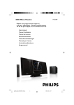
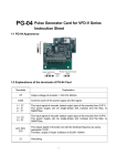
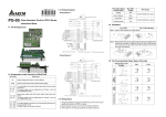
1
2007-04-12
A.
Y EMV-PG01O
Wiring 1
jumper
2.1 Outline
Braking resistor (optional)
Non-fuse breaker
5011647401-EM01
http://www.delta.com.tw/industrialautomation/
R
NFB
S
EMV-PG01 Instruction Sheet
T
REV/STOP
Multi-step 1
Factory
setting
Multi-step 2
Multi-step 3
1.1 Outline
U
S/L2
V/T2
V
T/L3
W/T3
W
+24V
FWD
REV
MI1
MI2
MI3
MI4
MI5
MI6
FWD/STOP
X EMV-PG01X
- +1 +2/B1 B2
R/L1
U/T1
Multi-step 4
No function
No function
Digital Signal Common
Motor
M
3~
PG OUT
Pulse output
VP
DCM
A1
A1
B1
B1
Z1
Z1
DCM
AB2: PG2 signal
mode switch
PG
Line driver
VP
A2
A2
B2
B2
DCM
AB2:
PG2 signal
mode switch
B.
ABZ1:
PG1 signal
mode switch
jumper
Non-fuse breaker
R
PG1
Pulse feedback
manual pulse generator
(MPG)
10- 17
10- 18
PG2
Pulse input
NFB
U
V
W
S/L2
T
T/L3
W/T3
+24V
FWD
REV
MI1
MI2
MI3
MI4
MI5
MI6
Multi-step 1
Multi-step 2
Multi-step 3
Multi-step 4
No function
No function
Digital Signal Common
1.2 Terminals descriptions
- +1 +2/B1 B2
R/L1
U/T1
S
REV/STOP
Factory
setting
Braking resistor (optional)
V/T2
FWD/STOP
DCM
Motor
M
3~
2.2 Terminals Descriptions
VP
DCM
A1
A1
B1
B1
Z1
Z1
Terminal Symbols
PG
Line driver
VP
VP
DCM
Descriptions
Power source of EMV-PG01X (use PS1 to switch 12V/5V)
Output Voltage: +5V/+12V±5% 200mA
phase difference is 90 o
Power source and input signal common
A1, A1
B1, B1
Z1, Z1
Input signal. Input type is selected by ABZ1. It can be 1-phase or 2-phase
input. Maximum 300kP/sec
A2, A2
B2, B2
Input signal. Input type is selected by AB2. It can be 1-phase or 2-phase
input. Maximum 300kP/sec
VCC
1.3 Wiring Notes
Please use a shielded cable to prevent interference. Do not run control wires parallel to any high
A2, A2
B2, B2
Input signal from encoder. Input type is selected by AB2. It can be 1-phase
or 2-phase input. Maximum 300kP/sec
AB2+PS1
12V
5V
12V
OC 12V
OC 12V
OC 12V
OC 12V
TP 5V
TP 5V
TP 5V
TP 5V
Output signal. It has division frequency function (Pr.10-16), open
collector: max. output DC20V 50mA
Grounding
VCC
Recommended wire size 0.21 to 0.81mm (AWG24 to AWG18).
OC 12V
OC 12V
Output Voltage
50m
Open Collector
50m
Line Driver
300m
Complementary
70m
Recommended wire size 0.21 to 0.81mm2 (AWG24 to AWG18).
2.4 Wire Length
TP 5V
TP 5V
TP 5V
TP 5V
Line driver
Q
OC 12V
OC 12V
OC 12V
OC 12V
Q
Complementary
TP 5V
TP 5V
TP 5V
TP 5V
The wire length and signal frequency are in inverse proportion.
Please use a shielded cable to prevent interference. Do not run control wires parallel to any high
voltage AC power line (200 V and above).
OC 12V
O/P
Maximum Wire Length
A.
B.
OC 12V
1.4 Wire Length
Types of Pulse Generators
2.3 Wiring Notes
0V
Open collector
2
The wire length and signal frequency are in inverse proportion.
0V
Wire Gauge
2
1.25mm (AWG16) or above
VCC
OC 12V
OC 12V
OC 12V
OC 12V
Types of Pulse Generators
Maximum Wire Length
Output Voltage
50m
Open Collector
50m
Line Driver
300m
Complementary
70m
O/P
TP 5V
0V
1.5 Basic Wiring Diagram
ABZ1+ PS1
O/P
voltage AC power line (200 V and above).
B.
Input signal from encoder. Input type is selected by ABZ1. It can be
1-phase or 2-phase input. Maximum 300kP/sec
A/O, B/O, Z/O
5V
Power source and input signal common
VOLTAGE
Grounding
A.
Power source of EMV-PG01O (use PS1 to switch 12V/5V)
Output Voltage: +5V/+12V±5% 200mA
A1, A1
B1, B1
Z1, Z1
1.6 Types of Pulse Generators (Encoders)
Types of Pulse Generators
Descriptions
incremental encoder
DCM
Terminal Symbols
PG2
Pulse input
PG1
Pulse feedback
Line driver
Wiring 2
PS1:
5/12V switch
PS1:
5/12V switch
ABZ1: PG1 signal
mode switch
incremental encoder
TP 5V
TP 5V
TP 5V
2.5 Basic Wiring Diagram
Wire Gauge
1.25mm2 (AWG16) or above
A.
Z EMV-PG01L
Wiring 1
jumper
NFB
R
S
T
REV/STOP
Multi-step 1
Factory
setting
Multi-step 2
Multi-step 3
Multi-step 4
No function
No function
Digital Signal Common
manual pulse generator
(MPG)
10- 17
10- 18
Line driver
B.
U
S/L2
V/T2
V
T/L3
W/T3
W
VP
A2
A2
B2
B2
DCM
jumper
Braking resistor (optional)
Non-fuse breaker
- +1 +2/B1 B2
R/L1
U/T1
+24V
FWD
REV
MI1
MI2
MI3
MI4
MI5
MI6
DCM
FWD/STOP
S
M
3~
T
PG OUT
pulse output
VP
DCM
A1
A1
B1
B1
Z1
Z1
FWD/STOP
REV/STOP
Factory
setting
AB2: PG2 signal
mode switch
R
NFB
S
T
No function
No function
Line driver
Digital Signal Common
ABZ1: PG1 signal
mode switch
incremental encoder
FWD/STOP
REV/STOP
Multi-step 1
Factory
setting
Multi-step 2
Multi-step 3
Multi-step 4
No function
No function
Digital Signal Common
PG2
pulse input
B.
R
Motor
M
3~
VCC
Terminal Symbols
PG
VP
Line driver
DCM
incremental encoder
phase difference is 90 o
ABZ1+PS1
5V
12V
OC 12V
OC 12V
OC 12V
OC 12V
TP 5V
TP 5V
0V
OC 12V
OC 12V
TP 5V
TP 5V
TP 5V
Line Driver
Q
OC 12V
OC 12V
OC 12V
OC 12V
Q
Complementary
TP 5V
TP 5V
TP 5V
TP 5V
OC 12V
OC 12V
TP 5V
0V
VCC
OC 12V
OC 12V
O/P
TP 5V
0V
TP 5V
TP 5V
TP 5V
Line driver
Multi-step 1
Multi-step 2
Multi-step 4
No function
Digital Signal Common
A2, A2
B2, B2
Input signal. Input type is selected by AB2. It can be 1-phase or 2-phase input.
Maximum 300kP/sec
AO, BO, ZO
AO, BO, ZO
Output signal. It has division frequency function (Pr.10-16), Line driver: max.
output DC5V 50mA
10- 17
10- 18
Line driver
- +1 +2/B1 B2
R/L1
U/T1
+24V
FWD
REV
MI1
MI2
MI3
MI4
MI5
MI6
DCM
Power source and input signal common
Input signal. Input type is selected by ABZ1. It can be 1-phase or 2-phase
input. Maximum 300kP/sec
manual pulse generator
(MPG)
Braking resistor (optional)
W/T3
VP
DCM
A1
A1
B1
B1
Z1
Z1
AO
AO
BO
BO
ZO
ZO
U
Motor
V
M
3~
W
PG
Line driver
incremental encoder
phase difference is 90 o
3.6 Types of Pulse Generators (Encoders)
Types of Pulse Generators
ABZ1
5V
AB2
5V
OC
OC
TP
TP
OC
OC
TP
TP
OC
OC
TP
TP
OC
OC
TP
TP
VOLTAGE
3.3 Wiring Notes
O/P
Please use a shielded cable to prevent interference. Do not run control wires parallel to any high
voltage AC power line (200 V and above).
B.
0V
2
Recommended wire size 0.21 to 0.81mm (AWG24 to AWG18).
Open collector
3.4 Wire Length
O/P
The wire length and signal frequency are in inverse proportion.
O/P
PG
VP
A2
A2
B2
B2
DCM
T/L3
VCC
OC 12V
M
3~
VP
DCM
A1
A1
B1
B1
Z1
Z1
T
No function
Power source of EMV-PG01L
Output Voltage: +5V±5% 200mA
Open Collector
OC 12V
+24V
FWD
REV
MI1
MI2
MI3
MI4
MI5
MI6
DCM
V/T2
VCC
A.
TP 5V
Descriptions
A1, A1
B1, B1
Z1, Z1
AB2+PS1
12V
O/P
VCC
W
S/L2
Multi-step 3
Grounding
5V
TP 5V
W/T3
S
REV/STOP
Factory
setting
VP
DCM
A1
A1
B1
B1
Z1
Z1
NFB
FWD/STOP
3.2 Terminals Descriptions
2.6 Types of Pulse Generators (Encoders)
VOLTAGE
T/L3
Motor
Wiring 2
Non-fuse breaker
W
W/T3
VP
DCM
A/O
B/O
Z/O
Types of Pulse Generators
S/L2
V
jumper
V
DCM
U
V/T2
incremental encoder
Braking resistor (optional)
V/T2
T/L3
- +1 +2/B1 B2
R/L1
U/T1
AO
AO
BO
BO
ZO
ZO
VP
DCM
A/O
B/O
Z/O
U
+24V
FWD
REV
MI1
MI2
MI3
MI4
MI5
MI6
Multi-step 2
Multi-step 4
PG
- +1 +2/B1 B2
R/L1
U/T1
S/L2
Multi-step 1
Multi-step 3
Wiring 2
Non-fuse breaker
NFB
R
Motor
PG1
pulse feedback
jumper
Wiring 1
3.1 Outline
Braking resistor (optional)
Non-fuse breaker
A.
Types of Pulse Generators
Maximum Wire Length
Wire Gauge
0V
Line driver
Q
Output Voltage
50m
Open Collector
50m
Line Driver
300m
Complementary
70m
3.5 Basic Wiring Diagram
Q
1.25mm2 (AWG16) or above
Complementary
VCC
O/P
0V
The content of this instruction sheet may be revised without prior notice. Please consult our distributors or download the most
updated version at http://www.delta.com.tw/industrialautomation