1
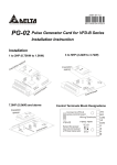
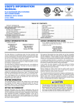
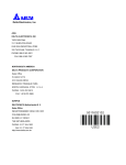
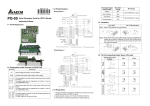
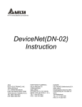
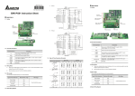
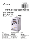
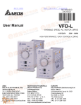
PG-04 Pulse Generator Card for VFD-V Series
Instruction Sheet
1-1 PG-04 Appearance
VP
Output terminal
Pulse input terminal
Input terminal
CH2
Power
CH1
A1A1 B1 B1 Z1 Z1
VP
A2 A2 B2 B2
1-2 Explanations of the terminals of PG-04 Card
Terminals
VP
DCM
Explanation
Output voltage of encoder: +12V±5% 200mA
Common point of the power supply and the signal
A1, A1
B1, B1
Z1, Z1
The input signal of encoder (select output type of the encoder from FJP1)
The power supply can be single-phase and 2-phase and the Max. is
500KP/Sec.
A2, A2
B2, B2
The input signal of encoder (select output type of the encoder from FJP4)
The power supply can be single-phase and 2-phase and the Max. is
500KP/Sec.
A/O, B/O,
Z/O
The output signal of encoder can set the dividing frequency by using
parameter 10-20.
The Max. output of Open Collector is DC24V 100mA.
Grounding
1
1-3 Wiring Notes
1. Using the shielded wire to prevent interference, and do not line up in parallel with
circuits of AC200V or above.
2. Recommended wire size: 0.21~0.81mm2 (AWG24~AWG18).
3. Wire length
The Output Types of the Encoder Max. Wire Length
Voltage
50m
Open Collector
50m
Line Driver
300m
Wire Gauge
1.25mm2(AWG18) or above
1.25mm2(AWG18) or above
Complementary
70m
2
1-4 Wiring Examples
Wiring Diagram 1
Jumper
Braking Resistor(Option)
Non-Fuse breaker
R
NFB
S
T
- +1 +2/B1 B2
U/T1
S/L2
V/T2
V
W/T3
W
T/L3
Multi-step4
Reset
E.F.
Digital common
MPG
10-08
10-12
Line driver
Main circuit (power) terminals
24V
FWD
REV
Mi1
Mi2
Mi3
Mi4
Mi5
Mi6
DCM
VP
A2
A2
B2
B2
DCM
Multi-function input terminals
Factory Default
FWD/STOP
REV/STOP
Multi-step1
Multi-step2
Multi-step3
U
R/L1
VP
DCM
A1
A1
B1
B1
Z1
Z1
Motor
M
3~
PG
Line driver
Line driver encoder
VP
DCM
A/O
B/O
Z/O
Control circuit terminals
3
Shielded leads & Cable
Wiring Diagram 2
Jumper
Braking Resistor(Option)
Non-Fuse breaker
R
NFB
S
T
Multi-step4
Reset
E.F.
Digital common
U/T1
S/L2
V/T2
V
T/L3
W/T3
W
24V
FWD
REV
Mi1
Mi2
Mi3
Mi4
Mi5
Mi6
DCM
EH-PLC
Y0
Y0
Y1
Y1
COM
U
R/L1
Multi-function input terminals
Factory Default
FWD/STOP
REV/STOP
Multi-step1
Multi-step2
Multi-step3
- +1 +2/B1 B2
A2
A2
B2
B2
DCM
VP
DCM
A1
A1
B1
B1
Z1
Z1
Motor
M
3~
PG
Line driver
Line driver encoder
VP
DCM
A/O
B/O
Z/O
Y0
Y0
Y1
Y1
Phase difference 90 o
Main circuit (power) terminals
Control circuit terminals
Recommended Wiring for Resistors
VP
Pull High Resistor
330
330
330
A/O
B/O
Z/O
DCM
4
Shielded leads & Cable
1-5 Installation
For 1-5HP
For 7.5 HP and above
Step 1: Insert 3 PCB supports into control board.
Step 2: Press the PG card on the control board to be fixed to tighten the 3 screws with a
torque of 4-6kgf-cm. If the PG card is not fixed on the control board, it may cause
screw idle running and cannot turn the screw into supports.
5
1-6 The corresponding output types of encoder
Output Types of the Encoder
FJP1
FJP4
Voltage
VCC
TP
TP
oc
oc
TP
TP
oc
oc
TP
TP
oc
oc
TP
TP
oc
oc
O/P
Open collector
0V
VCC
O/P
Complementary
Line driver
0V
Q
Q
VCC
O/P
0V
2007-07-16
5011614303-G4E3
ASIA
DELTA ELECTRONICS, INC.
TAOYUAN Plant/
31-1, SHIEN PAN ROAD,
KUEI SAN INDUSTRIAL ZONE TAOYUAN
333, TAIWAN, R.O.C
TEL: 886-3-362-6301
FAX: 886-3-362-7267
NORTH/SOUTH AMERICA
DELTA PRODUCTS CORPORATION
Sales Office/
P.O. BOX 12173, 5101 DAVIS DRIVE, RTP,
NC 27709, U. S. A.
TEL: 1-919-767-3813
FAX: 1-919-767-3969
6
EUROPE
DELTRONICS (Netherlands) B.V.
Sales Office/
Industriegebied Venlo Nr. 9031,
Columbusweg 20, NL-5928 LC Venlo
The Netherlands
TEL: 31-77-324-1930
FAX: 31-77-324-1931