1
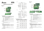
2007-07-12
5011606104-PG E4
PG-02
Pulse Generator Card for VFD-B Series
Installation Instruction
Installation
3 to 5HP (2.2kW to 3.7kW)
1 to 2HP (0.75kW to 1.5kW)
In
la
su
t io
n
a
sp
ce
r
PG
PG
Ca
rd
-
Insu latio n
spa cer
02
PG
Te
rm
ina
l
t i c ff
as o
P l and
t
S
C
tr
on
ol
7.5HP (5.5kW) and above
Insu latio n
spa cer
PG-
b
oa
rd
PG
rd
Te
rm
ina
2
l
l bo
ard
Control Terminals Block Designations
Connect to VFD-B
series control board
Wiring Terminals
02
Car
Ca
-0
tro
Con
PG-02
Pl a
S t a s ti c
nd
off
PG
d Te
rmi
nal
FSW2 FSW1
Select the power
source and output
of Pulse Generator
OC 12V
TP 5V
A/O
B/O
COM
VP
DCM
A
A
B
B
2
PG Card and Pulse Generator
B. Basic Wiring Diagram with RPM
Meter Attached.
A. Basic Wiring Diagram
None Fused Breaker
R/L1
NFB
R/L1
U/T1
Motor
S/L2
S/L2
V/T2
IM
3~
T/L3
T/L3
W/T3
NFB
R/L1
U/T1
Motor
S/L2
S/L2
V/T2
IM
3~
T/L3
T/L3
W/T3
R/L1
VFD-B
PG-02
OC 12V
Factory
Default
TP 5V
A
A
B
B
A
A
B
A
A
A
B
B
OC 12V
PG
B
TP 5V
+12V
VP
GND
DCM
E
Pulse Generator
Output 12V DC
VP
DCM
E
A/O
B/O
COM
E
A
B
+5V
GND
RPM meter
PG-02 and Pulse Generator Connections
PG-02 and Pulse Generator Connections
C. When Pulse Generators is Open Collector type, please wire as following.
NFB
R/L1
U/T1
Motor
S/L2
S/L2
V/T2
IM
3~
T/L3
T/L3
W/T3
R/L1
PG-02
OC 12V
Factory
Default
TP 5V
A
A
B
B
A
B
+12V
VP
GND
DCM
E
Pulse Generator
Output 12V DC
PG-02 and Pulse Generator Connections
PG
PG
B
3
PG-02 Terminal Descriptions
Terminals
Terminal Symbols
VP
DCM
Descriptions
Power source of PG-02 (FSW1 can be switched to 12V or 5V)
Output Voltage: (+12VDC ±5% 200mA) or (+5VDC ±2% 400mA)
Power source (VP) and input signal (A, B) common
Input signal from Pulse Generator. Input type is selected by FSW2.
Maximum 500KP/Sec
A/O, B/O
COM
PG-02 output signal for use with RPM Meter.
Maximum DC24V 300mA
PG-02 output signal (A/O, B/O) common.
Wiring Notes
The control, power supply and motor leads must be laid separately. They
must not be fed through the same cable conduit / trunking.
1.
Please use a shield cable to prevent interference. Do not run control wire parallel to any
high voltage AC power line (220 V and up).
2.
Connect shielded wire to
3.
Recommended wire size 0.21 to 0.81mm2 (AWG24 to AWG18).
4.
Wire length:
E only.
Types of Pulse
Generators
Maximum Wire Length
Output Voltage
50m
Open Collector
50m
Line Driver
300m
Complementary
70m
Wire Gauge
1.25mm2 (AWG16) or above
4
Types of Pulse Generators
Output Voltage
VCC
Open collector
Types of Pulse Generators
VCC
FSW2 FSW1
OC 12V
FSW2 FSW1
OC 12V
O/P
TP 5V
TP 5V
FSW2 FSW1
FSW2 FSW1
TP 5V
TP 5V
Q
FSW2 FSW1
FSW2 FSW1
Q
TP 5V
TP 5V
FSW2 FSW1
FSW2 FSW1
TP 5V
TP 5V
0V
OC 12V
OC 12V
O/P
0V
Line driver
Complimentary
FSW1 and FSW2 switches
12V
5V
OC 12V
OC 12V
VCC
OC 12V
OC 12V
O/P
0V
ASIA
DELTA ELECTRONICS, INC.
TAOYUAN Plant/
31-1, SHIEN PAN ROAD,
KUEI SAN INDUSTRIAL ZONE
TAOYUAN 333
TEL: 886-3-362-6301
FAX: 886-3-362-7267
NORTH/SOUTH AMERICA
DELTA PRODUCTS
CORPORATION
Sales Office/
P.O. BOX 12173
5101 DAVIS DRIVE
RTP, NC 27709 U. S. A.
TEL: 1-919-767-3813
FAX: 1-919-767-3969
EUROPE
DELTRONICS (Netherlands) B.V.
Sales Office/
Industriegebied Venlo Nr. 9031
Columbusweg 20
NL-5928 LC Venlo
The Netherlands
TEL: 31-77-324-1930
FAX: 31-77-324-1931