1
Storage Center 5.5
System Manager
User Guide
Storage Center System Manager 5.5 User Guide
680-019-009
Revision
Date
Description
A
03/16/11
Initial release for Storage Center 5.5.2
B
4/12/11
Updated to include new locations for contacting Dell technical support and downloading
product manuals and other editorial changes and corrections.
Disclaimers
Information in this document is subject to change without notice.
Trademarks and Copyright
Trademarks used in this text: DellTM, the DELLTM logo, and CompellentTM are trademarks of Dell Inc.
Other trademarks and trade names may be used in this document to refer to either the entities claiming the
marks and names or their products. Dell Inc. disclaims any proprietary interest in trademarks and trade
names other than its own.
© 2011 Dell Inc. All rights reserved.
Contents
Preface
Purpose vii
Related Publications vii
Contacting Dell Support Services
1
vii
Introduction
What’s New in this Release 2
Introducing the Storage Center System Manager
Navigation 12
2
7
Quick Start Guide
Introduction 16
3
Servers
Introduction 28
Servers 29
Server Clusters 32
Virtual Servers 42
Common Server Commands 45
Managing HBAs 47
Managing Server Folders 52
Viewing Server Information 54
Topology Explorer Server Functions 62
4
Volumes
Introduction 66
Creating Volumes 67
Mapping Volumes to a Server 73
Import Data to Lowest Tier 80
Creating a Boot from SAN Volume 82
Modifying Volumes 86
Managing Volume Folders 91
Applying Replay Profiles 95
Copy, Mirror, and Migrate 97
iii
Viewing Volume Information 100
Recycle Bin 108
Topology Explorer Volume Functions 109
5
Disks
Introduction 114
Viewing Tiers 115
Adding Disks to a Storage Center System 116
Configuring Storage 120
Rebalancing RAID 122
Managing Disks 126
Managed Disk Folders 130
Importing from External Device without Replication License 133
Non-Standard Storage Types 138
6
Controllers
Introduction 142
About Controller Virtual Ports 143
Viewing Controller Properties 144
Viewing Controller Status 146
Viewing FC Folders and Cards 150
Viewing iSCSI Cards 159
Creating a Remote Storage Center Connection 173
Configuring Remote Connections Using CHAP 181
Viewing SAS Cards 190
Rebalancing Local Ports 194
7
System Management
Setting Up a Storage Center 196
Configuring Local Ports 201
Configuring iSCSI IO Cards 211
Allowing Replications to/from Remote Systems 212
Viewing Licensed Applications 213
Configuring System Access via IP Filtering 214
Viewing Disk Space Usage Summary 220
SNMP Server 227
Viewing System Properties 229
Selecting RAID Stripe Width 230
Data Progression 232
Setting System Cache 234
Configuring Global Disk Spares 235
Adding Optional Information about Storage Center 236
Finding Unmanaged Hardware 237
Viewing Background Processes 240
Phoning Home 241
Viewing the System Log 243
Responding to the Alert Monitor 244
Monitoring Storage Space 247
Changing the Storage Alert Threshold 248
Adding Space 249
iv
Storage Center 5.5 System Manager User Guide
Adding a Controller 250
Shutting Down and Restarting 252
Upgrading Storage Center Software 253
8
Users and Groups
Introduction 262
User Privilege Levels 263
Viewing Users 264
Changing User Properties 268
Configuring User Volume Defaults
Managing User Groups 277
9
272
Data Instant Replay
Introduction 284
Viewing Replay Profiles 285
Applying Replay Profiles to Volumes 288
Viewing Volumes Attached to a Replay Profile
Creating Replay Profiles 292
Adding Replay Profile Rules 300
Managing Replay Profiles 305
Recovering Data 321
10
290
Remote Instant Replay
Introduction 328
Synchronous and Asynchronous Replications 329
Estimating Bandwidth 330
Disallowing Replications Between Storage Center Systems
Establishing Physical Connectivity 332
Defining a QoS 333
Creating Volumes on a Remote System 338
Mapping an Existing Volume to a Remote System 339
Creating Replications 341
Creating a Simulated Replication 342
Viewing Replications 346
Modifying Replications 348
Re-creating a Volume from a Replication 349
11
Charting Viewer
Introduction 352
Downloading and Installing Charting Viewer
Using Charting Viewer 353
Viewing Storage Center Charts 356
Printing a Chart 357
Saving a Chart as a PNG Image 358
Zooming In and Out 358
12
331
353
Additional Hardware
Introduction 360
v
Enclosures 360
Removing an Enclosure 371
Uninterruptable Power Supply (UPS) 373
Racks 374
13
IO Card Changes
I/O Card Change Wizard
A
380
Storage Profiles
Overview 382
Changing User Volume Defaults 383
Storage Profiles Created by the System
Creating Custom Storage Profiles 385
Managing Storage Profiles 388
Manual Storage Mode 392
B
Portable Volume
Introduction 398
List of Portable Volumes
C
384
398
Enterprise Solid State Drives
Overview 402
Installation and Setup 403
D
Configuring a UPS
Introduction 406
Configuring an APC™ UPS 406
Configuring a Liebert™ UPS 411
E
Server HBA Settings
Introduction 416
Settings by HBA Vendor 416
Settings by Server Operating System
419
Glossary 425
vi
Storage Center 5.5 System Manager User Guide
Preface
Purpose
The Storage Center System Manager User Guide describes the Storage Center System
Manager software that manages an individual Storage Center system.
Related Publications
Compellent Storage Center documentation consists of the following publications:
•
Storage Center System Manager Setup Guide
Describes how to set up a new Storage Center.
•
Storage Center System Manager Upgrade Guide
Describes how to upgrade Storage Center software from version 4.5.6 and above to
version 5.5 and from version 5.0 and higher to version 5.5.
•
Storage Center Enterprise Manager User Guide
Describes how to use Enterprise Manager to view and manage one or more Storage
Centers, as well as generate and view charts and reports on Storage Center usage
statistics. In addition, describes how to use Remote Instant Replay to replicate Replays
to one or more Storage Centers.
To download Dell Compellent product manuals, go to:
http://www.dell.com/manuals
Contacting Dell Support Services
Please contact Dell Technical Support Services from the following address if you need
support assistance:
http://support.dell.com/compellent
vii
Preface
viii
Storage Center 5.5 System Manager User Guide
1
Introduction
What’s New in this Release 2
Introducing the Storage Center System Manager 7
Starting the Storage Center System Manager 7
Possible Messages on System Manager Startup 9
Navigation 12
View Menu 14
1
Introduction
What’s New in this Release
Congratulations on making the move to Fluid Data storage from. The new Fluid Data
architecture combines a powerful data movement engine, virtualized software applications
and an agile hardware platform to intelligently manage data at a more granular level. The
patented technology optimizes performance, lowers costs and increases storage
utilization.
Storage Center 5.5
iSCSI Configure IO Card Wizard Improvements
All iSCSI cards are now configurable using the iSCSI Configure IO Cards wizard. In
previous releases, only uninitialized cards could be configured via this wizard. In addition,
all iSCSI IO cards detected by the system can now be configured from a single window
rather than configuring cards one at a time on separate windows. This functionality can be
accessed via the Startup Wizard and via Storage Center System Explorer through multiple
paths.
Search Capability added to GUI
A search capability has been added to the bottom of the system tree in System Explorer.
The search feature provides the ability to search through the system tree for objects . A
dropdown menu allows filtering objects by type: All (default), Volumes, Disks, Servers. Left
and right arrows allow navigating forward and back. An arrow to the left of the search field
allows you to minimize/maximize the search function. A checkbox is provided to match
case.
Configure Local Ports Changes
Front-end values for Fibre Channel ports attached an enclosure can no longer be set via
the Configure Local Ports wizard. In support of this change, a Enclosure Connected column
has been added to the FC ports table (virtual port and legacy port modes).
Demoting Volume Mappings from a Server Cluster to an Individual Cluster Node
In earlier versions of Storage Center, users were required to demote server cluster
mappings one at a time. In this version, users can demote multiple cluster mappings at the
same time using the Demote Mappings to Server Cluster Nodes window.
Restore Deleted User Wizard
The Restore Deleted User wizard enables users to select the deleted user to be restored
and provide a new password for the restored user.
Allow Replays to Coalesce into an Active Replay
The Volume Properties screen now displays an option to allow Replays for the displayed
volume to coalesce into the active Replay. This option is unselected by default. As part of
this change, the Space Consumption Limit and Import Data To Lowest Tier options have
also been moved from the General tab to the new Advanced tab of the Volume Properties
window.
2
Storage Center 5.5 System Manager User Guide
What’s New in this Release
OpenVMS Unique Disk IDs Displayed
The Volume Properties screen now allows the user to set the Open VMS Unique Disk Id for
the volume. This attribute is used by Open VMS to uniquely identify the volume. It is
ignored by other operating systems.
Log Filter Improvements
Users can now select a log filter timeframe from a dropdown menu on the Filter Log
Messages window. On dual-controller systems, logging can be set per controller. The
default is to show all log messages.
Enabling / Disabling Secure Console Access
If secure console access to the Storage Center was configured, menu options to restart and
disable this access are now available on the Storage Management > System menu. The
new menu options provide easy access to common secure console actions previously
available only within the Configure Secure Console wizard.
Storage Center 5.4
Model 40 Storage Controller (CT-SC040)
The Model 40 storage controller is based on the SuperMicro X8DTH-iF motherboard with
Intel Nehalem chipset technology.
Fibre Channel over Ethernet – 10Gb
This release adds Fibre Channel over Ethernet (FCoE) capabilities to the product line via
the QLogic FCoE CNA QLE8152 IO card. This card provides PCI Express dual 10Gbps
Ethernet ports with full hardware offload for FCoE protocol processing. While the QLE8152
is capable of standard TCP/IP and Ethernet processing, Storage Center only supports the
card for FCoE capabilities. The card must be connected to a CISCO Nexus 5000 series
switch.
Fibre Channel – 8Gb
This release provides a second source for 8Gb Fibre Channel interfaces via the QLogic
QLE2564 PCI Express, quad port, Fibre Channel adapter. This card provides functional
equivalence to the existing Emulex 8Gb Fibre Channel card and can be used in addition to
as well as a replacement for the Emulex card.
SAS – 6 Gb
This release provides the next step in performance and scalability of the storage back-end
technology with the introduction of SAS 2.0 compliant 6G IO cards to communicate with
new SAS 2.0 6G compliant enclosures and disk drives. The LSI SAS 9200-16e is a quad
wide port full height PCI-e card with support for 16 lanes of 6Gb interfaces. The initial
release of SAS 6G provides support for 48 devices per chain, with the ability to have two
chains of devices per IO Card. SAS connections are described in greater detail in the
Storage Center 5.4 SAS Connections Guide, document number 680-049-001.
3
Introduction
iSCSI Card – Enhanced 10Gb Support
This release provides 10Gb iSCSI support for additional network interface, switches, and
server operating systems beyond what was available in the previous release, including
support for the Chelsio S320E-CR (PCIe based) adapter. This is a dual-port IO card utilizing
the Chelsio T3 (terminator 3) ASIC for 10 Gb offload processing.
IO Card Change Wizard
The new IO Card Change Wizard provides a user interface within the Storage Center
System Manager to the utility used to map hardware changes to existing configurations.
The wizard can be used for IO card upgrades and removals or when upgrading controllers.
For more information, see Storage Center 5.4 I/O Change Wizard, document number
685-001-001 available through Dell Support Services.
Storage Center 5.3
iSCSI Card – Limited 10 Gigabit Support
This release introduces limited support for the Chelsio S320E-CR 10Gbps iSCSI card.
Configure Operational Mode
Legacy and Virtual Port operational mode can be selected during initial system setup for a
new Storage Center when Virtual Ports are licensed. This feature is described in the
Storage Center System Setup Guide, document number 680-022-007. After initial system
setup, ports can be configured within Storage Center Manager by using the Configure
Local Ports wizard.
Configure Local Ports Wizard
The redesigned Configure Local Ports wizard combines Legacy and Virtual Port
configuration in a single wizard. The Configure Local Ports screen displays a list of
controllers, slots, and ports present on the Storage Center. For each IO card and port used
on each controller, you can specify a network value of front end or back end and a usage
of primary or reserved.
iSCSI Qualified Names (IQNs)
In previous releases, servers were created using WorldWide Names (WWNs) for HBAs.
Users now have a choice when creating servers — WWN or iSCSI Name. The default is
iSCSI Name. For server ports, the iSCSI name is a user-defined string that might follow the
conventional iSCSI Qualified Name (IQN) format, but does not have to, and is intended to
be globally unique. The Storage Center does not impose the IQN format for servers and
enforces uniqueness only within a single Storage Center system.
Storage Center 5.2.2
Server Cluster
Storage Center 5.2.2 enables the selection of volumes to be promoted to a server cluster
when creating the cluster. Previously, all volumes mapped to server nodes were
automatically promoted to the Server Cluster. Once a volume is mapped to a Server
Cluster, it can be demoted from the Server Cluster to a server node. When a volume is
mapped to a server node, it can be promoted to a Server Cluster.
4
Storage Center 5.5 System Manager User Guide
What’s New in this Release
Import Mode
Import Mode allows you to import data directly to the lowest configured tier of storage.
Advanced Mapping Display
An option exists to allow advanced mapping information to be displayed. By default, this
option is turned off.
Storage Center 5.2.1
RAID 6
In addition to RAID 10 and RAID 5-5/5-9, Storage Center allows you to select RAID 6 for
any storage tier. RAID 6 provides greater storage redundancy and efficient use of disks.
Secondary DNS Server
Users now have the option of entering a secondary DNS server. If a path is not available to
the primary DNS server, the Storage Center connects to the secondary DNS server.
Import from External Device
Previously, a synchronous replication license was required for data to be loaded from an
external device. Now the command to Import from an External Device and Classify Disk as
External are available without a synchronous replication license. Import from External
Device uses synchronous replication to import data from a non-Storage Center device.
Storage Center 5.1
System Dashboard
The license window that appeared in previous versions of the System Manager is replaced
with a System Dashboard that displays used and available storage space, and a history of
storage use. The Dashboard lets you monitor your space more efficiently. The license
window is available from the Help menu.
Storage Center 5.0
Virtual Ports
Virtual Ports eliminate the need for reserve ports. When operating in Virtual Port mode all
front-end ports accept IO.
Consistency Groups
Consistency Groups create a synchronized Replay of all volumes within the consistency
group while the IO stream on all volumes is halted. This creates a consistent data set.
Consistency Groups can also be replicated to other Storage Centers.
Mapping
Storage Center adds the ability for you to identify the operating system of each server so
that it can map Volumes to Servers based on the rules of the operating system of the server.
5
Introduction
Portable Volume
A Portable Volume is a removable USB drive that moves large quantities of data between
replicating systems to establish a baseline replication. Portable volumes are configured in
Enterprise Manager.
Leibert™ UPS
Storage Center 5 supports the Liebert Uninterruptable Power Supply. The UPS is now
managed through SNMP.
SAS
Storage Center 5 supports SAS (Serial Attached SCSI) protocol enclosures and disks. SAS
achieves data transfer speeds on four wide lanes of each SAS port
6
Storage Center 5.5 System Manager User Guide
Introducing the Storage Center System Manager
Introducing the Storage Center System Manager
The Storage Center System Manager:
•
Provides a central management interface to create and manage Storage Center
volumes, servers, disks, and users.
•
Displays the status of hardware components.
•
Enables local and remote backup and restore.
•
Provides Phone Home technical support.
•
Allows multiple users to have different levels of access privileges.
In addition to the System Manager, Storage Center provides a rich set of separatelylicensed applications that support dynamic storage. To view currently licensed applications,
from the Help menu, select Licensed Features.
Note Figures in this document show views, menus, and options displayed when logged in
with Administrator privileges. If you are logged in as a Volume Manager or Reporter,
what you see displayed may differ from the figures and options described in this User
Guide.
Starting the Storage Center System Manager
Access Storage Center System Manager from a workstation or PC on the same network as
the Storage Center controller. View the Storage Center System Manager through one of
these browsers:
•
Microsoft Windows Internet Explorer Versions 7, 8, and 9
•
Mozilla Firefox Version 3 on Microsoft Windows
If you log on using an unsupported browser, the system returns a warning stating that some
functions of the Storage Center software may not function as expected.
Note The Storage Center System Manager cannot load with the following unique
combination of applications: Windows 2008 (64 bit), FireFox 3.0, and Java Runtime
Environment 6_10.
To start Storage Center System Manager
1 In the address bar of the web browser, enter the name or IP address of the
Management controller. (This was configured during setup.) A security alert appears.
2 Click Yes to acknowledge the alert. The Storage Center System Manager login window
appears.
7
Introduction
Figure 1. Login Window
3 In the User ID field, enter the default ID:
Admin
4 Enter the default password:
mmm
5 Click Login. If an additional security alert appears, click Yes to continue.
Note The End User License Agreement is displayed the first time a new user logs onto the
Storage Center. Click Accept to continue.
8
Storage Center 5.5 System Manager User Guide
Introducing the Storage Center System Manager
Possible Messages on System Manager Startup
Unbalanced Local Ports
If a controller has been added or taken offline, ports can become unbalanced. The Startup
wizard warns you if local ports are unbalanced.
To balance unbalanced ports
Click Yes to rebalance local ports.
To turn off the rebalance ports message
1 Select the Controllers node.
2 From the shortcut menu, select Rebalance Local Ports.
3 Uncheck the option to check for unbalanced local ports at startup.
IO Card Change Detected
If an IO card change is detected on system startup, Storage Center will automatically
launch the IO Card Change Wizard. For information about this wizard, refer to I/O Card
Change Wizard on page 380.
Unmanaged Hardware
If the System Manager finds unmanaged hardware, such as disks or server host bus
adaptors (HBAs), it prompts you to manage them. For more information on managing
unassigned disks, refer to Adding Unassigned Disks to a Folder on page 119. For more
information on HBAs, refer to Managing HBAs on page 47.
Viewing the System Explorer
When the system recognizes the user name and password, the System Explorer opens.
•
Storage Management menu: Displays Storage Center commands.
•
Shortcut menu: The shortcut menu appears when you select a component. It is
displayed at the top of the System Explorer below the menus as well as when you rightclick an component. The Shortcut menu displays commands specific to the selected
component.
•
System Tree: Shown in the left frame of the System Explorer, the System Tree displays
logical and physical components.
•
View menu: Displays different views of the system.
•
Alert Monitor: Displays component status. Click the System Status button to view
additional information including the system log.
•
Advisor Pages: Most windows, include advisor pages with additional information
about commands and information displayed in the window. To open an advisor page,
click on the Advisor button.
9
Introduction
System Dashboard
The center frame of the System Explorer opens to the System Dashboard.
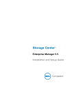
Figure 2. System Explorer View
The Storage Summary displays:
• Date and time the summary report was generated
• Status: Normal or Space Low. Space Low indicates that you must add storage.
• Total disk space: The amount of raw disk space available.
• Used disk space: Space used by volumes and replays (blue on the bar graph)
• Free disk space: Space available for volumes and replays (gray in the bar graph).
• Unhealthy/Bad space (if any) Space found on any unhealthy disks, or any bad space
found on disks which are healthy. This appears only if unhealthy or bad disk space has
been found (black in the bar graph).
• A bar graph on the right edge of the window shows the Storage Alert Threshold. If free
space falls below the Low Space Threshold, the System Manager sends an alert,
warning you to add additional disks.
• Search function in the lower left provides the ability to search through the system tree
for objects with matching names. A dropdown menu allows filtering objects by type: All
(default), Volumes, Disks, or Servers. A checkbox is provided to match case (default).
Left and right arrows allow you to navigate forward and backward. The arrow to the left
of the search field allows you to minimize/maximize the search panel.
10
Storage Center 5.5 System Manager User Guide
Introducing the Storage Center System Manager
Storage History
The Storage History displays an overview of past storage use:
•
Numbers on the left showing the amount of disk space in GB.
•
Blue line shows the amount of space used recently.
•
Red line shows the amount of raw disk space available.
•
Yellow line shows the Storage Alert Threshold
Note In rare instances, a Storage Center system will have more than one disk folder. In
this case, the System Manager displays a Storage Summary and Storage History for
each disk folder.
11
Introduction
Navigation
Storage Management Menu
To view System Manager commands, click the Storage Management menu, directly below
the title bar.
Figure 3. Storage Management Menu
System Tree
Expand component folders in the System Tree to view component status.
Figure 4. System Tree
12
Storage Center 5.5 System Manager User Guide
Navigation
Shortcut Menu
Select an item in the system tree to view a shortcut menu for that item. Commands in the
shortcut menu also appear at the top of the System Explorer window.
If there is not sufficient room to display all shortcut menu commands at the top of the
window, a down arrow is displayed. Click the arrow to display all commands shown in the
shortcut menu.
Shortcut menu
Shortcut menu commands
Down arrow
Figure 5. Shortcut Menu
13
Introduction
Selecting Multiple Components
To perform one command on multiple similar components:
1 In the system tree, select a component folder, such as Volumes or Assigned Disks.
2 In the main window, using the Shift or Ctrl key, select multiple objects. The shortcut
menu above the main window displays commands available to multiple objects. For
example, clicking on the Volumes folder icon and selecting volumes in the main window
allows you to delete multiple volumes at once or move multiple volumes to a new folder.
View Menu
Click View to open the View menu.
Figure 6. View Menu
The View menu provides multiple ways to configure a system or view system properties.
Options are specific to each individual view. To display the view menu, click the View menu
at the top of the Storage Center window.
Once a View window is open, the tab for that view appears at the top of the window.
Figure 7. Open View Tabs
If a tab is displayed, click the tab to display the view window. View windows remain open
during a Storage Management session. Close a view window and tab by clicking on the X
in the right corner of the tab. If more tabs are available than can be displayed, click the scroll
arrows at the far right of the tabs to scroll through the open tabs. Selecting a view that is
already opened displays the window; it does not open a second window. Set Update
Frequency, Find, and Scroll Setting appear at the top of most views.
14
Storage Center 5.5 System Manager User Guide
2
Quick Start Guide
Introduction 16
Step 1. Manage Unmanaged Hardware 16
Step 2. Change Admin Password 17
Step 3. Create Servers 18
Step 4. Configure Your User Volume Defaults 20
Step 5. Create Multiple Volumes 23
Step 6. Monitor Alerts - Ongoing 25
15
Quick Start Guide
Introduction
Though Storage Center has many sophisticated commands, the following six steps allow
you to initially manage a Storage Center system.
A fully redundant system has no single point of failure, as long as a failing physical
component is replaced in a timely manner. Storage Center monitors all of the physical
components, including storage space consumed and available. User properties allow you
to enter up to three telephone numbers (include cell phones) to IT personnel. Alerts inform
you of system and component status.
Step 1. Manage Unmanaged Hardware
It is assumed that the hardware attached to the Storage Center controller was identified
during Installation. If not, Storage Center recognizes unmanaged hardware and asks that
you manage it. If all hardware is managed, turn to Step 2 on page 17.
Storage Center groups disks into a disk folder to create one pool of storage from which
volumes are created. By using one disk folder, you maximize Thin Provisioning and
Dynamic Capacity. Managing unassigned disks means to move them into a managed disk
folder.
To manage unassigned disks
1 In the system tree, expand Disks.
2 Open the Unassigned Disk Folder.
3 From the list of disks, select disks to be managed. For the most efficient use of the
Storage Center, select all the disks.
4 Click Continue. The Select Hot Spare window appears. A hot spare replaces a failed
disk. It is held in reserve until needed. A spare disk must be as large or larger than the
largest disk in the disk folder. At least one hot spare must be reserved for each
enclosure. The system selects the optimal disk to be a spare. Accept the default or
select one or more disks to be used as a hot spare(s).
5 Click Continue. The disk folder confirmation window appears. The default name for the
disk folder is Assigned. Enter another name or accept the default. Optionally, enter
notes for the folder.
6 After verifying all disk folder information, click Create Now. The system asks you to
confirm. Click OK.
7 Select a Disk Folder.
8 From the shortcut menu, select Configure Storage. The System Manager combines
the disks into a single pool of storage from which to create volumes.
9 When the system informs you of the type of storage that it prepared, click Close.
Note If the system asks you to Rebalance RAID devices, select Rebalance Now. For
more information, refer to Rebalancing RAID on page 122
16
Storage Center 5.5 System Manager User Guide
Introduction
Step 2. Change Admin Password
Note You must be an administrator to change this password.
To change the Admin password
1 In the system tree, click the Users icon to view users.
2 Select the an icon, such as Admin.
3 From the shortcut menu, select Change User Password. The Change User
Password window appears.
4 Enter and re-enter a password.
5 Click OK. The password is changed.
17
Quick Start Guide
Step 3. Create Servers
To create a new FC or iSCSI server
1 In the Storage Management window, select the servers folder.
2 From the shortcut menu, select Create Server. The Create Server wizard appears,
listing HBAs recognized by the Storage Center.
Figure 8. Create Server
3 Select one or more HBAs and click Continue. A window appears asking you to name
the server.
Figure 9. Name Server
18
Storage Center 5.5 System Manager User Guide
Introduction
4 Enter a name for the server or accept the default.
5 From the drop-down menu, select an operating system for this server. Volumes will be
mapped to this server according to the rules of the operating system of the server.
6 Select an existing server folder or create a new server folder. To create a folder at this
time, click Create a New Folder. Enter a folder name and any notes (up to 255
characters). Click OK.
7 Click Continue.
8 Click Create Now. The commands that appear in this window depend on the action you
just completed.
Figure 10. Server Created Window
9 Click Close.
19
Quick Start Guide
Step 4. Configure Your User Volume Defaults
There are defaults for volumes you create. You can change properties for any individual
volume, but if you are going to create many volumes, streamline the process by configuring
the volume defaults.
To configure your user volume defaults
1 In the system tree, click the Users icon to view users.
2 Select your user icon, such as Admin.
3 From the shortcut menu, select Configure User’s Volume Defaults. The Configure
User Volumes Defaults window appears.
Figure 11. General User Volume Defaults
4 Select a default disk folder from which to draw storage. The default is the folder you
created in Step 1 on page 16.
5 If you enabled system-wide cache in setup, enable or disable cache for volumes you
create. Check or clear the Allow Changes box to the right of the Cache options.
20
Storage Center 5.5 System Manager User Guide
Introduction
6 Enter a Volume Size. The default is 500 GB. Remember, this space is not reserved,
only allocated. This means that you can allocate more disk space than you actually
have. You need to add additional disks when the space actually used reaches 80% of
total physical space.
7 Select or disable Show block size in volume wizards.
8 Enter a Base Volume Name. When you create many volumes at once, the System
Manager increments this name by one. As you quickly add volumes, the names appears
as New Volume 1, New Volume 2, New Volume 3, etc.
Set Volume Replay Defaults
Volume Replays defaults set the default Replay schedule for volumes you create.
To configure volume Replays
1 In the Configure User Volumes Defaults window, select the Replay tab. The default
Replay schedule appears.
Figure 12. Set Volume Replay Defaults
2 From the dropdown menu at the top of the window, choose to be queried for a Replay
schedule when you create a volume or to automatically use the default Replay schedule
for new volumes.
21
Quick Start Guide
3 Select a default Replay Profile. The rules in these two Replay Profiles cannot be
changed. (To create your own Replay schedule, refer to the instructions in Creating
Replay Profiles on page 292.)
4 Enter a Minimum Allowed Replay Interval or accept the default. A minimum allowed
Replay restricts the intervals between Replays.
Set Mapping Defaults
Mapping Defaults selects a default sever to which to map volumes.
To configure mapping defaults
1 In the Configure User Volumes Defaults window, click on the Mapping tab.
2 From the servers you created in Step 3 on page 18, select a server to which to
automatically map the volumes you create. For more information on mapping options,
including advanced options, refer to User Volume Defaults - Mapping on page 275.
Confirm user volume defaults
When you have changed volume defaults, click OK. Volumes you create will be created
with these defaults.
22
Storage Center 5.5 System Manager User Guide
Introduction
Step 5. Create Multiple Volumes
To create multiple volumes
1 In the system tree, select Storage.
2 From the shortcut menu, select Create Volumes. The Create Volumes window
appears.
Figure 13. Create Multiple Volumes
3 Select Use My Volume Defaults when adding a volume. (The Copy the selected
volume when adding a volume command lets you add volumes based on properties
other than your volume defaults.)
23
Quick Start Guide
4 Continue to click Add Volume for as many volumes as you want to create.
Figure 14. Added Volumes
5 When you have added sufficient volumes, click Create Volumes Now. (This may take
several minutes. The system advises you of its progress.)
When the creating volume window closes, the system manager displays the first volume
you created. Volume type is Dynamic Write until Storage Center creates the first
Replay. Data can now be written to the volumes.
24
Storage Center 5.5 System Manager User Guide
Introduction
Step 6. Monitor Alerts - Ongoing
Add Space as Required
Disk drives that are managed by the Storage Center are contained in a disk folder, which
is simply a logical grouping of physical drives. Disk folders can contain a mixture of drive
types, capacities, and speeds. The total capacity of the disk folder is the sum of the
capacities of the drives within the folder. Disk folders also contain disk drives that are
specified as hot spares. Hot spare drives are reserved for use as replacement drives in the
event another disk in the disk folder fails. Since the space on these hot spares is never used
until another drive fails, their capacity is not included in the total capacity for the disk folder.
Storage Center allocates disk space from a disk folder for volume and Replay use as
needed based upon the configurations and IO patterns of each volume. As the Storage
Center approaches the end of the disk space available within the disk folder, it will generate
an alert, warning you to add additional space.
Conservation Mode
Storage Center enters Conservation Mode when remaining free space reaches 32 GB (or
less for systems smaller than 3.2 TB). When Storage Center enters conservation mode, the
system generates a Conservation Mode Alert to inform you that the system will not allow
new volumes to be created and that it will begin to aggressively expire Replays. The
Conservation Alert is close to the boundary where space is exhausted to keep these
actions from being performed unless necessary. Because of its proximity to the emergency
threshold, it is not a tool to manage storage, and should not be used to plan adding
additional disks to the system.
Emergency Mode
Emergency threshold means that the system can no longer operate because there is no
more free space. Storage Center:
•
Generates an emergency alert
•
Expires Replays early
•
Will not permit new volumes to be created
•
All volumes are taken offline
When Storage Center reaches the Emergency threshold, all server IO is rejected until the
system gets out of Emergency Mode. Because this is service affecting, special care should
be taken to monitor free space on the system to avoid reaching this threshold. Volumes will
not be able to be brought back online until enough space is freed to exit the emergency
state. Before a system reaches Emergency Mode, it is critical that you add space. Refer to
Conservation Mode on page 25.
Monitor Physical Components
Alerts warn you of component failure when the Storage Center requires attention. The
status of the Storage Center is indicated by the color of the System Status icon in the topright corner of the System Manager.
•
Red (Critical) The System Status icon appears red when an alert exists that has a status
of Down, Critical, or Emergency. When the System Status icon is red, this indicates a
condition that requires immediate attention.
25
Quick Start Guide
•
Yellow (Warning) The System Status icon is yellow when an alert exists that has a status
of Degraded or Unavailable. This indicates a condition of which you should be aware,
but which does not require immediate attention.
•
Green (Normal) The System Status icon appears green when no alerts exist, when the
only alerts that exist are to inform you. The System Status icon returns to green when
all alerts higher than Inform are acknowledged.
To view the System Alert monitor
Click System Status at the top of the System Explorer. The Alert Monitor view appears.
Click the Alerts folder to view all alerts.
Figure 15. Alert Monitor
Selecting an alert displays additional information about the system message. To view more
information about an alert, select an Alert. The shortcut menu displays additional
commands.
1 Click Show to display the object in the System Manager. Some alerts do not have a
related object to be shown. For these alerts, the Object column is blank.
2 To acknowledge an alert, select Acknowledge. Acknowledging an alert acknowledges
it for all users.
3 Click the Advanced tab in the Alert Properties window to display a reference number.
The reference number may be important for communication with Dell Support Services.
26
Storage Center 5.5 System Manager User Guide
3
Servers
Introduction 28
Servers 29
Server Clusters 32
Virtual Servers 42
Common Server Commands 45
Managing HBAs 47
Managing Server Folders 52
Viewing Server Information 54
Topology Explorer Server Functions 62
27
Servers
Introduction
This chapter describes how to create, manage, and monitor servers. Defining a server
enables Storage Center to pass IO through the ports on that server. Once a server is
created, volumes can be mapped to it. Storage Center automatically recognizes FC IO
cards within the network to which is connected. iSCSI IO cards must be configured either
during setup or as they are added to the network. A remote Storage Center can act as a
server to a local Storage Center for Replication, as described in Remote Instant Replay on
page 327.
Servers can be organized into server folders either to make them easier to manage or as
a means to restrict access to servers, as described in Users and Groups on page 261.
Several servers can be combined into a Server Cluster. The Storage Center views the
Server Cluster as one server. Volumes can be mapped to the Server Cluster or to a server
that is a member of the cluster. Refer to Creating a Server Cluster on page 32
One server or server cluster can be the host of one or more virtual servers. Each virtual
server can have a different operating system. The Storage Center views each virtual server
as a separate entity. Volumes mapped to one virtual server are not mapped to other virtual
servers residing on the same server. Refer to Creating a Virtual Server on page 42.
Server Icons
In the System Tree, the System Manager uses icons to denote the server type.
Icon
Server Type
Server Node - all servers
Folder
Server
Server Cluster
Virtual Server
Remote Systems Node
HBA Node - FC, iSCSI, or SAS - resides under the controller node
28
Storage Center 5.5 System Manager User Guide
Servers
Servers
Note For information on preparing an iSCSI server that is recognized by a Storage Center
system, refer to the Storage Center Setup Guide.
Creating a Server
Creating a server means to identify it to a Storage Center system by using the Create
Server wizard. If you are using iSCSI CHAP, add remote CHAP initiators to communicate
with the server. Refer to Adding a Remote CHAP Initiator on page 182.
To create a server
1 In the system tree, select the servers node.
2 From the shortcut menu, select Create Server. The Create Server wizard appears. The
wizard lists Host Bus Adapters (HBAs) recognized by the Storage Center.
Figure 16. List of Available HBAs
3 Select one or more HBAs. For information on finding an HBA, refer to Finding an HBA
on page 48.
Note If you select an iSCSI HBA, you have the option to create the server using WWNs or
iSCSI Qualified Names (IQNs) for HBAs. Default is iSCSI Name.
29
Servers
4 Click Continue. A window allowing you to name the server appears.
Figure 17. Name Server Window
5 Enter a name for the server or accept the default. Enter a folder name and any notes
(up to 255 characters).
6 From the drop-down menu, select an operating system (OS) for the server. Default is
Windows 2008. All servers must have an OS defined. Expand operating system folders
to view operating system versions.
Figure 18. Example of an Expanded Operating System Folder
7 Volumes are mapped to servers according to the rules of the server operating system.
To view rules of an operating system, select a system.
8 Click Continue. The screen displays the name and attributes of the server. Click the
question mark icon. A window opens displaying rules for the selected operating system.
30
Storage Center 5.5 System Manager User Guide
Servers
Figure 19. Server Name and Attributes
9 Click Create Now. On the next window, choose from the following options:
•
Map the server to a Volume
•
Map a different Server to a Volume
•
Create Volume
•
Create Server
10 Close the Create Server wizard
Note For a short time after a server is created, it may appear in the system tree with an
error icon while Storage Center re-evaluates its server connectivity. When the
System Manager is refreshed, the error icon disappears when the server is visible to
Storage Center.
31
Servers
Server Clusters
A server cluster is a collection of servers. A server that is a member of a server cluster is
referred to as a cluster node. Volumes can be mapped directly to a server cluster. All
volumes mapped to a server cluster are automatically mapped to all nodes in the cluster.
This increases IO efficiency and, if one server fails, IO continues to other servers within the
cluster. Volumes can also be mapped to only one of the nodes within the server cluster.
Some operating systems require that a volume mapped to multiple cluster nodes use the
same LUN on each node. When creating a server cluster, Storage Center attempts to map
an included volume to the same LUN on all cluster servers. If the LUN selected is not
available on a particular server, the mapping is not performed and the volume is only
partially connected to the cluster.
Note All servers within a server cluster must have the same operating system.
Creating a Server Cluster
1 In the system tree, select the servers node.
2 From the shortcut menu, select Create Server Cluster.
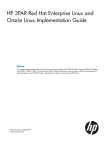
Figure 20. Create Sever Cluster Wizard
3 Choose one of the buttons at the bottom of the window and follow the instructions in the
wizards.
32
Storage Center 5.5 System Manager User Guide
Server Clusters
Creating New Servers for Server Cluster
1 Select Create New Server.
2 Follow Steps 3 though 9 for creating a server, starting on page 29. When you select
Create Now, the Create Server Cluster window shown in Figure 20 reappears.
To create a second server to add to a server cluster
1 Select Create New Server.
2 Repeat Steps 3 through 9, starting on page 29.
Note All servers in the server cluster must have the same operating system. If a server is
incorrectly selected to be in the cluster, use the Remove Selected Server button to
remove the server from the list before creating the server cluster.
3 When all the servers that will be part of this cluster are listed, click Continue. A window
allowing you to name the server cluster appears.
Figure 21. Name Server Cluster Window
4 Name the server cluster or accept the default. Add notes if necessary.
5 Click Continue. The system asks you to confirm.
6 Click Create Now.
7 On the next window, map volumes to the server cluster or click Close.
33
Servers
Notice that the server cluster appears in the system tree.
Figure 22. System Tree Showing Server Cluster
Adding a Server to a Server Cluster
1 In the Create Server Cluster window, select Add Existing Server.
2 Expand a server folder to view servers within the folder, if necessary, and select a
server.
Figure 23. Select Server to Add to Cluster
3 Click Continue. The Create Server Cluster window reappears.
34
Storage Center 5.5 System Manager User Guide
Server Clusters
Figure 24. Create Server Cluster Window
4 Add another server by clicking Add Existing Server again. The Create Server Cluster
window reappears with the servers listed in the Select Servers frame. The window
displays the operating systems of the selected servers.
Note All servers in the server cluster must have the same operating system. If a server is
incorrectly selected to be in the cluster, use the Remove Selected Server button to
remove the server from the list before creating the server cluster.
5 Once the Create Server Cluster window displays all the servers for this server cluster,
click Continue. A window allowing you to name the server cluster appears.
6 Name the server cluster or accept the default. Add notes if necessary.
7 Click Continue. If volumes were mapped to individual server nodes, the system
displays a list of mapped volumes and asks you to select volumes to map to the server
cluster. By default, the system selects all volumes mapped to the server nodes, except
boot volumes; by default, boot volumes are not selected to be mapped to the server
cluster.
35
Servers
Figure 25. Select Volumes to Promote to Server Cluster
8 Click Continue. The system asks you to confirm.
9 Click Create Now.
10 From the next window, map volumes or click Close. Notice that the server cluster
appears in the system tree.
36
Storage Center 5.5 System Manager User Guide
Server Clusters
Creating a Server Cluster from Selected Servers
1 In the system tree, select the server node or other server folder. A list of servers in that
folder appears.
2 In the main window, select servers to be added to the server cluster.
Figure 26. Creating Server Cluster from Selected Servers
3 From the shortcut menu, select Create Server Cluster. The Create Server Cluster
window appears with the servers you selected.
Note All servers in the server cluster must have the same operating system. If a server is
incorrectly selected to be in the cluster, use the Remove Selected Server button to
remove the server from the list before creating the server cluster.
4 Click Continue. A window allowing you to name the server cluster appears.
5 Name the server cluster or accept the default. Add notes if necessary.
6 Click Continue. If volumes were mapped to individual server nodes, the system
displays a list of mapped volumes.
7 Select volumes to map to the server cluster. By default, the system selects all volumes
mapped to the server nodes, except boot volumes.
8 Click Continue.
9 The system asks you to confirm.
10 Click Create Now.
11 On the next window, map volumes or click Close. Notice that the servers were moved
from the server folder to the new server cluster.
37
Servers
Moving an Existing Server to a Server Cluster
1 In the system tree, select a server that is a not a member of a server cluster. From the
shortcut menu, select Move Server to Cluster. The Move Server to Cluster window
appears with a list of server clusters.
2 Select a server cluster.
3 Click Continue. The system asks you to confirm.
4 Click Apply Now. Volumes that were mapped to the server cluster are now mapped to
the server that was added.
Removing a Server from a Server Cluster
1 In the system tree, select a server that is a member of a server cluster. From the
shortcut menu, select Remove Server from Cluster. The Remove Server from
Cluster window appears.
2 Click Remove Now. Because volumes mapped to the server cluster are mapped to all
servers within the cluster, removing a server from a cluster does not affect volumes
mapped to the cluster.
Removing Multiple Servers from a Server Cluster
1 In the system tree, select a server cluster.
2 From the shortcut menu, select Remove Servers from Cluster. The system displays a
list of servers that are members of this cluster.
Figure 27. Remove Servers from Cluster
3 Select one or more servers to remove. Click Continue.
4 The system asks you to confirm. Click Remove Now.
38
Storage Center 5.5 System Manager User Guide
Server Clusters
Deleting a Server Cluster
Before you can delete a server cluster, you must remove or delete all the server nodes
within the server cluster.
To delete a server cluster
1 Make sure all nodes that were part of the cluster are removed or deleted. In the system
tree, select an empty server cluster.
2 From the shortcut menu, select Delete. The system asks you to confirm.
3 Click OK.
Promoting and Demoting Server Cluster Mappings
The Storage Center allows users to demote mappings from server clusters to the individual
cluster nodes and to allow users to promote mappings from individual cluster nodes to a
server cluster.
To promote server cluster mappings
Once a volume has been mapped to a server node, it can be promoted from that server
node to a server cluster.
1 In the system tree, select a server cluster.
2 From the shortcut menu, select Promote Mappings to Server Cluster. The Promote
Mappings to Cluster window appears.
Figure 28. Select Mappings to Promote
3 Select the mapping to promote by highlighting it.
39
Servers
4 Click Continue. The resulting window displays the volume selected for promotion and
the name of the server cluster to which it will be mapped.
Figure 29. Promote Selected Mappings
5 Click Promote Now to promote volume mappings or click Cancel to exit.
To demote server cluster mappings
Once a volume has been mapped to a server cluster, it can be demoted from that server
cluster to a server node.
1 In the system tree, select a server cluster.
2 From the shortcut menu, select Demote Mappings to Server Cluster Nodes. The
Demote Mappings to Cluster Nodes window appears showing current mappings.
Figure 30. Select Mappings to Demote
3 Use the check boxes to select mappings to be demoted.
40
Storage Center 5.5 System Manager User Guide
Server Clusters
4 Click Continue. The resulting window lists servers in the cluster and the volumes that
are mapped to the servers.
Figure 31. Demote Selected Mappings
•
Checked server mappings will be demoted from the cluster to the server. By default,
all server mappings are checked.
•
Unchecked server mappings will be deleted from the server.
5 Click Demote Now to demote volume mappings or click Cancel to exit.
41
Servers
Virtual Servers
Creating a Virtual Server
1 In the system tree, select a server.
Figure 32. Select Server
2 From the shortcut menu, select Create Virtual Server. A list of available HBAs appears.
3 Click Continue. A window allowing you to name virtual server appears.
4 Enter a name or accept the default.
5 From the drop-down menu, select an operating system that can act as an OS for a
virtual machine, such as Windows 2008.
6 Enter notes, if necessary.
7 Click Continue. A confirmation window appears.
8 Click Create Now. The virtual server appears under the host server you selected.
42
Storage Center 5.5 System Manager User Guide
Virtual Servers
Figure 33. Virtual Server in System Tree
There is no limit on the number of virtual servers you can create on a server.
Converting a Server to a Virtual Server
1 In the system tree, select a server.
2 From the shortcut menu, select Convert to Virtual Server. The system asks you to
select a host server or server cluster for the selected servers.
Note The destination server or server cluster must be running an operating system that
can act as a virtual server host, such as VMWare ESX or Windows 2008.
3 In the system tree, select a server or server cluster. Click Continue. A confirmation
window appears.
4 Click Convert Now. The clustered server is converted to a virtual server.
43
Servers
Converting a Virtual Server to a Physical Server
To convert a virtual server into a server
1 From the system tree, select a virtual server. From the shortcut menu, select Convert
to Server. The Convert Virtual Server to Physical Server window appears.
Figure 34. Convert Virtual Server to Physical Server
2 Click Convert Now. The other virtual servers remain virtual. Only the server you
converted to a physical server is removed from the virtual server group.
Deleting a Virtual Host Server
1 In the system tree, select a virtual host server.
2 From the shortcut menu, select Delete. The system warns you that deleting a virtual
host server also deletes all virtual servers attached to the host.
3 Click Yes. The virtual host server and all virtual servers attached to the host are deleted.
44
Storage Center 5.5 System Manager User Guide
Common Server Commands
Common Server Commands
Renaming a Server
1 In the system tree, select a server.
2 From the shortcut menu, select Properties. The Server Properties window appears
with the General tab selected. This tab shows the server name and operating system.
Figure 35. General Server Properties
3 Enter a new name. Enter any notes (up to 255 characters).
4 Click OK. The server is renamed.
Changing the Operating System of a Server
If an operating system changes on a server because of an operating system upgrade or an
operating system capability changes from single path to multipath, you may need to change
the operating system of the server in Storage Center.
To change the operating system of a server
1 In the system tree, select a server.
2 From the shortcut menu, select Properties. The Server Properties window appears
with the General tab selected.
3 Select a new operating system. Enter any notes (up to 255 characters).
4 Click OK. The operating system of that server is changed.
45
Servers
Displaying Alerts When Server Connection is Lost
You may wish to disable alerts. For example, when you are doing scheduled maintenance,
you may not need to be notified that connectivity to a server is lost.
To disable alerts
1 In the system tree, select a server.
2 From the shortcut menu, select Properties. The Server Properties window with the
General tab selected appears.
3 Check Do not show alerts when connectivity to this server is lost..
4 Click OK.
Deleting a Server
Deleting a server returns HBAs connected to that server to the list of available HBAs.
To delete a server
1 In the system tree, select a server.
2 From the shortcut menu, select Delete. The system asks you to confirm.
3 Click Yes. The server is deleted. Deleting a server cluster deletes all the servers within
the cluster. Deleting a server node within a server cluster deletes only that server node.
Deleting a server that is part of a virtual server deletes only that server.
46
Storage Center 5.5 System Manager User Guide
Managing HBAs
Managing HBAs
Adding HBAs to a Server from a List
If you added a new card to a server, you can logically identify it to the Storage Center
system.
To add an HBA to a sever
1 In the system tree, select a server.
2 From the shortcut menu, select Add HBAs to Server. The Add HBAs to Server
window appears. In the Connected Controller Ports column, the System Manager lists
the server ports connected to this controller.
Figure 36. Add HBAs to Servers
3 Choose the HBAs you want to display: FC, iSCSI, or only Up connections.
Note When you click Refresh, the System Manager does not scan for new HBAs; it
merely re-displays the current list of HBAs.
4 Select an HBA.
Note If you select an iSCSI HBA, you have the option to create the server using WWNs or
iSCSI Qualified Names (IQNs) for HBAs. Default is iSCSI Name.
5 Click Continue. The Storage Center System Manager asks you to confirm.
6 Click Modify Now.
47
Servers
Finding an HBA
1 In the system tree, select a server. From the shortcut menu, select Add HBAs to
Server. The Add HBAs to Server window appears.
2 Click Find HBA. The system asks if the server is already cabled to the network.
•
If you click Yes, the system asks you to make sure that the network acknowledges the
HBA.
a
b
c
d
e
•
Locate and unplug the cable to the HBA on the back of the server.
Wait 60 seconds.
Plug the cable going to the HBA back into the server.
Click Find HBA again.
Select an HBA. Click Continue. The system asks you to confirm.
If you click No:
a Plug the server into the FC Network or create a connection by logging on to the iSCSI
portal.
b Wait 30 seconds
c Click Continue.
Note If the system does not see a new HBA, check the cabling and connections. Click
Scan Again.
48
Storage Center 5.5 System Manager User Guide
Managing HBAs
Manually Defining an HBA
1 In the system tree, select a server. From the shortcut menu, select Add HBAs to
Server.
2 In the Add HBA to Server window, click Manually Define HBA. The Add HBAs to
Server window appears.
3 Select a Transport Type and enter a World Wide Name or iSCSI name for the HBA.
Figure 37. Manually Define HBA
4 Select a transport type: FC or iSCSI.
5 Click Continue. The HBA you entered is shown in the list of HBAs.
6 Select the HBA you defined.
7 Click Continue. The HBA is added to the server.
Removing HBAs from a Server
Before removing an HBA, make sure that no volumes are mounted to this server through
this HBA. If you remove an active HBA, the server that is using the volume no longer has
access to that volume and will receive read or write errors. When you map a volume to a
server, you are really mapping that volume to one (or possibly more than one) of the server
HBAs. When you remove an HBA to which a volume is mapped, the maps are also deleted.
Note Note that when an HBA is removed from a server, any mapping through those HBA
ports will be automatically reevaluated and moved to other HBA ports on the server
if any are available.
49
Servers
To remove HBAs from a server that does not have volumes mapped to it
1 In the system tree, select a server.
2 From the shortcut menu, select Remove HBAs from Server. Storage Center System
Manager displays the HBAs on that server.
3 Select an HBA.
4 Click Continue. The system asks you to confirm.
5 Click Remove HBAs Now. The HBA is removed.
Deleting an HBA
1 In the system tree, select a server.
2 Click on the HBA tab.
3 From the shortcut menu, select Delete. The Storage Center System Manager asks you
to confirm.
4 Click Yes.
50
Storage Center 5.5 System Manager User Guide
Managing HBAs
Remove Mappings from a Server
You can either select a volume and remove the mapping to the server, or select a server
and remove volumes mapped to it. This command is similar for servers, server clusters, or
virtual servers.
To remove mappings from a server
1 In the system tree, select a server.
2 From the shortcut menu, select Remove Mappings from a Server. The system
displays volumes mapped to that server.
3 Select mappings to remove.
•
Make sure that the volume mapped to this server is no longer mounted; if you
remove an active map entry, the server using the volume will have read/write errors.
The system warns you if you are attempting to remove an active map entry.
•
Make sure that removing this mapping will not create a gap in the LUN sequence.
Most operating systems require contiguous LUN sequencing starting with LUN 0. A
gap in the LUN sequence may cause the server to fail to recognize subsequent
volumes.
4 Click Remove Now. The mapping is removed.
51
Servers
Managing Server Folders
Creating a Server Folder
You can use server folders to organize servers and to restrict access to servers by some
users. Servers folders can be hierarchical. Folders appear in the system tree under the
servers node.
To create a server folder
1 In the system tree, select a server.
2 From the shortcut menu, select Create Server Folder. The Create Server Folder
window appears.
3 Enter a name or accept the default.
4 Enter any notes (up to 255 characters).
5 Click OK.
Adding Servers to a Server Folder
1 In the system tree, select one or more servers.
Figure 38. Select Multiple Servers
2 From the shortcut menu, select Move to Folder. The Storage Center System Manager
displays a list of folders.
3 Select a folder.
4 Click Continue. The Storage Center System Manager asks you to confirm.
52
Storage Center 5.5 System Manager User Guide
Managing Server Folders
5 Click Apply Now.
Moving Servers to a Different Folder
1 In the system tree, select a server. From the shortcut menu, select Move to Folder.
The Move Servers window appears, displaying server folders.
2 Select a folder to which to move the server.
3 Click Continue. System Manager displays the server and the folder path.
4 Click Apply Now.
53
Servers
Viewing Server Information
Viewing Server General Information
1 In the system tree, select the servers node. The main window displays a list of servers
or server folders. To view a server within a folder, in the system tree, select a server.
The server information window with the General tab highlighted appears.
Figure 39. General Server Information
Server information includes:
54
•
Name: Applied when server was created. To change the name, refer to Renaming a
Server on page 45. Another Storage Center system that is acting as a server to the
current system is identified by its Storage Center name. Another Storage Center system
acts as a server to the current system if it is replicating data to the current system.
•
Index: Number used by Dell Support Services to assist with component identification.
•
Folder: If this Server is organized into a folder, the folder in which it resides.
•
Type: Server, Virtual Server, or Server Cluster
•
Operating System: Displays server operating system
•
Connectivity: Displays connection status of the server.
•
Date: Displays date created and updated, and by whom.
•
Notes: if any.
Storage Center 5.5 System Manager User Guide
Viewing Server Information
Viewing Server HBAs
Note Server HBAs do not appear in the server cluster window.
1 In the system tree, select a server. The server information window appears with the
Server HBAs tab highlighted.
Figure 40. Viewing Server HBAs
2 Click the Server HBAs tab. The Server HBAs window appears. The system displays:
•
Type: FC or iSCSI
•
Server Port: IQN or WWN for iSCSI, WWN for FC
•
Status: Up or Down
•
Connectivity: Displays connection status of the server port.
•
Port information: Displays Port ID, Node Name, and other identifying information.
•
Connected controller port ID(s)
55
Servers
Viewing Server Connectivity
1 In the system tree, select a server.
2 Click the Connectivity tab. The ports listed in the Server HBA window are displayed.
Figure 41. Viewing Server Connectivity
Note The figure above shows a sample connectivity window for iSCSI. For Fibre Channel,
this window displays the WWN and there is no IP address, Subnet Mask, or
Gateway.
The Connectivity window displays individual HBAs connected to the Storage Center across
controller ports and fault domains.
56
Storage Center 5.5 System Manager User Guide
Viewing Server Information
Viewing a Server Connectivity Report
Note Server Connectivity Report appears only if the system does not have Virtual Ports.
1 From the View menu, choose Server Connectivity. The Server Connectivity view
appears. The left side of the Server Connectivity window lists:
•
WorldWide Name (WWN)
•
Name of server
•
Type of server
•
Port type of FC or iSCSI
2 Scroll to the right to view additional information for each server. For each server, the
view displays:
•
System to which the server is connected
•
Server Port ID
•
Fault domain
•
Usage: Primary or Reserved
•
Server type of FC or iSCSI
System to which server is connected
Figure 42. Server Connectivity View
57
Servers
Viewing Server Mapping
1 In the system tree, select a server. The server information window appears in the right
frame.
2 Click on the Mapping tab. The mapping window appears.
Figure 43. Volumes Mapped to Selected Server
The server mapping tab shows the volumes to which the server is mapped and a mapping
detail panel showing additional information about the way in which the volume is mapped
to the server.
If the server selected is a virtual server, the virtual server mapping window shows the
volumes that are mapped to the virtual server. When a volume is selected, details are
displayed. Information includes whether the volume is mapped to the virtual server, the host
server of the virtual server, or both.
58
Storage Center 5.5 System Manager User Guide
Viewing Server Information
Figure 44. Viewing Virtual Server Mappings
Viewing Advanced Mapping Details
You can view advanced mapping details only if your user volume defaults permit you to. For
information on how to enable Advanced Mapping Details, refer to User Volume Defaults
- Mapping on page 275. If Advanced Mapping Details and Show Advanced Mapping
Details are both enabled, in addition to the mapped volume, volume folder, and server, the
Mapping window displays the information described in Advanced Mapping Options on
page 74.
Information displayed depends whether the volume is mapped to a:
•
Server with HBA ports of different transport types (such as Fibre Channel and iSCSI)
•
Server with multiple server HBA ports. Select Specify Server Ports. Select the ports to
be used.
•
Clustered server
•
Virtual server
•
If the operating system of the server supports multipathing.
Viewing Volumes Mapped to a Server
1 In the system tree, select a server. The server information window appears.
2 Click the Volumes tab. The system displays the volumes that are mapped to this server,
including volume name, type of volume, whether the volume is redundant, the amount
of disk space consumed by the volume, and the logical size of the volume.
59
Servers
Viewing Volumes Mapped to a Server Cluster
If the servers selected form a server cluster, the mapping window displays the volumes that
are mapped to the server cluster. Select a volume to view details about the way that volume
is mapped to the server cluster, including cluster node information.
Viewing Volumes Mapped to a Virtual Server
If the servers selected form a virtual server, the mapping window display shows the
volumes that are mapped to the virtual server. Select a volume to view details about the
way that volume is mapped, including whether the volume is mapped to the virtual server,
the host server of the virtual server, or both.
Figure 45. Viewing Volumes Mapped to a Virtual Server
Viewing Volumes Mapped to a Remote System
If the servers selected is a remote system, the Mapping window displays the volumes that
are mapped to that remote system. Select a volume to view details about the way that
volume is mapped to the remote system.
60
Storage Center 5.5 System Manager User Guide
Viewing Server Information
Figure 46. Viewing Volumes Mapped to a Remote System
Server Charts
1 In the system tree, select a server.
2 In the server information window, click on the Charts tab.
•
The top of the window displays reads, writes, and total KB per second
•
The bottom of the window displays reads, writes, and total IO per second
61
Servers
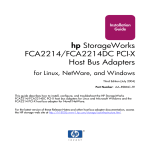
Topology Explorer Server Functions
With Topology Explorer you can map volumes to servers and external (remote) systems
easily by dragging components. The Topology Explorer is divided into three columns. The
left column displays servers. The middle column displays volumes, and the right column
displays external (remote) systems.
•
The Connections button, located above the right column, toggles between showing all
connections and showing connections only for selected objects. Numbers that appear
on the connection lines between servers and volumes indicate the logical unit for the
mapping. If there are Replications, there will also be connection lines between volumes
and the remote volumes to which they are Replicating.
•
The Folders button, located to the right of the Connections button, toggles between
showing and hiding volume folders. When the Folders button is toggled to show folders,
a red line is drawn through the Folders button and unmapped folders are displayed.
When the Topology Explorer displays folders, two additional command objects appear
at the bottom of the window: Create New Server Folder and Create New Volume
Folder.
The following two server functions are available through Topology Explorer command
objects:
•
Create New Server object opens the Create Server wizard
•
Create New Server Folder opens the Create Server Folder wizard
For information about Topology Explorer volume functions, see Topology Explorer
Volume Functions on page 109.
To open the Topology Explorer
From the View menu, select Topology Explorer.
Figure 47. Topology Explorer
62
Storage Center 5.5 System Manager User Guide
Topology Explorer Server Functions
Creating a New Server with the Topology Explorer
1 Drag the New Server command object to the Topology Explorer window. The Create
Server wizard appears.
2 Follow the instructions described in Creating a Server on page 29.
Creating a New Server Folder with the Topology Explorer
1 Make sure the Show Folders toggle is enabled and the Show Folder command object
appears.
2 Drag the New Server Folder command object to the Topology Explorer window. The
Create New Server Folder wizard appears.
3 Follow the instructions described in Creating a Server Folder on page 52.
63
Servers
64
Storage Center 5.5 System Manager User Guide
4
Volumes
Introduction 66
Creating Volumes 67
Mapping Volumes to a Server 73
Creating a Boot from SAN Volume 82
Viewing Volume Information 100
Modifying Volumes 86
Managing Volume Folders 91
Applying Replay Profiles 95
Copy, Mirror, and Migrate 97
Recycle Bin 108
Topology Explorer Volume Functions 109
65
Volumes
Introduction
This chapter describes creating and managing volumes. Volumes can be created only from
an assigned folder of managed disks.
A volume is a logical storage repository. You can allocate more logical space to a volume
than is physically available on the Storage Center.
Because user access to a volume is controlled by user groups and associated volume
folders and volumes, group volumes into folders based on the way you want to control user
access. You can then create a corresponding user group and grant access to that volume
folder or volume. (Refer to Users and Groups on page 261.)
Types of Volumes
A volume is a single accessible storage area with a single file system. It is the same as a
logical drive. Via RAID, a Storage Center volume is physically located on some or all of the
drives within a Disk Folder. In a Microsoft Operating system, a volume can be assigned a
drive letter; in UNIX, a volume is assigned a mount point. A volume can be one of the
following:
66
•
Standard Volumes are described in this chapter.
•
Portable Volumes and Remote Volumes are described in Remote Instant Replay on
page 327.
Storage Center 5.5 System Manager User Guide
Creating Volumes
Creating Volumes
Creating a Volume
Volumes are configured through the Configure Volume Defaults window. If some Create
Volume options do not appear, defaults were configured to disallow these choices. For
more information about User Volume Defaults, refer to Configuring User Volume Defaults
on page 272.
To create a volume with the Create Volume wizard
1 From the Storage Management window, select Create > Volume.
2 The Create Volume wizard asks you to enter a volume size.
Figure 48. Create Volume Window
3 Enter a volume size in GB, TB, or PB. The maximum size of a volume is 10 PB.
Note If your User Volume Defaults allow you to modify cache settings or Storage Profiles,
an Advanced button appears.
•
For more information about Cache settings, refer to To change volume cache
properties on page 88.
•
For more information about Storage Profiles, refer to Storage Profiles on page 381.
4 Click Continue.
67
Volumes
If Data Instant Replay is licensed for your system, the Replay Profile window appears.
Figure 49. Select Replay Profile
5 Select an existing Replay Profile, or click Create a New Replay Profile. For more
information about creating Replay profiles, refer to Creating Replay Profiles on
page 292.
6 Click Continue. The window on which you can select or create a folder and name the
volume appears.
7 Select a folder in which to create the volume or create a new folder.
8 Enter a volume name or accept the default.
9 Click Continue. The system displays the attributes of the volume.
Figure 50. Volume Attributes
10 Review the attributes. The attributes depend on the options available to you when
creating volumes. Click Create Now.
Note Volumes are automatically mapped to the last server you selected.
68
Storage Center 5.5 System Manager User Guide
Creating Volumes
Next Action Window
This next window presents options that are available after creating a volume.
Figure 51. Next Action Window
Depending on your configuration, some or all of the following commands may appear in this
window:
•
Map this Volume to this Server
•
Map this Volume to a Different Server
•
Map this Volume to a Remote System
•
Map a different Volume to this Server
•
Map a different Volume to a different Server
•
Create a Volume
•
Create a Server
•
Close this window
69
Volumes
Creating Multiple Volumes for a Server
The Create Volumes wizard creates multiple volumes and maps them to a server in a single
operation.
Note Adding a volume to the volume list in the Create Volumes for Server wizard does not
cause the volume to be created. Volumes are only created when you select Create
Volumes Now.
To create volumes for a server
1 In the system tree, select a server, server cluster, or virtual server.
2 From the shortcut menu, select Create Volumes. The Create Volume window appears.
By default, the name of the volume is based on the name of the server.
Figure 52. Create Volumes from Server
3 Review Add Volume options:
•
Copy the selected volume when adding a volume: The added volume copies all
attributes except name from the volume currently selected in the volume list.
•
Use My Volume Defaults when adding a volume: The added volume uses your
user volume defaults for creating a volume. Refer to Configuring User Volume
Defaults on page 272.
•
Map Volumes to this server using default settings upon creation: Checking this
automatically maps volumes to this server after they are created using default
mapping options. If there are special considerations for mapping volumes to this
server, uncheck Map Volumes to this server using default settings and manually map
the volumes to the server later.
4 Choose from the following:
70
Storage Center 5.5 System Manager User Guide
Creating Volumes
•
To add an additional volume to be created, click Add Volume. Adding a volume to
the volume list does not cause the volume to be created. Volumes are only created
when you click Create Volumes Now.
•
Continue to click the Add Volume button to add and map multiple volumes.
•
To remove the volume currently selected in the volume list, click Remove Selected
Volume.
•
To modify the volume currently selected in the volume list, click Modify Selected
Volume. If you are creating multiple volumes, modify the first volume in the list and
make sure the Copy the selected volume when adding a volume box is checked.
•
To create volumes, click Create Volumes Now . If the Map Volumes to this server
using default settings upon creation checkbox is selected, the volumes will be
automatically mapped to the selected server after they are created
Creating Multiple Volumes
Create volume options are configured through the Configure Volume Defaults window. If
some Create Volume options do not appear, defaults were configured to disallow these
choices. For more information about User Volume Defaults, refer to Configuring User
Volume Defaults on page 272.
Note If you intend to add multiple volumes with similar attributes, you should modify the
first volume in the list, then copy the attributes from this volume when adding
additional volumes.
To create multiple volumes
1 In the Storage Tree, select Storage or Volumes, from the shortcut menu, select
Create Volumes. The Create Volumes window appears.
Figure 53. Create Multiple Volume Window
71
Volumes
2 Choose a Volume Option:
•
Select Copy selected volume when adding a volume to copy all volume attributes
except name from the volume currently selected in the volume list. The name is
incremented by one number: Volume 1, Volume 2, etc.
•
Select Use My Volume Defaults when adding a volume to use your Volume
Defaults.
3 Select Add Volume to add additional volumes. (Volumes are not created until you click
Create Volumes Now.) Volumes are added to the list of volumes to create.
4 Select Remove Selected Volume to remove the volume currently selected in the
volume list.
5 Select Modify Selected Volume to modify the volume currently selected in the volume
list. The Modify Volume window appears.
Depending upon the user preferences you have selected, you may not be allowed to
change certain attributes. To change your user preferences, select the root of the
System Explorer tree and select Configure My Volume Defaults. Possible modifications
include:
•
Name
•
Size
•
Folder in which volume resides, or create a new folder
•
Replay Profile, or create a new Replay Profile
•
Storage Profile
•
Disk folder to select the disk folder for the volume to use. The disk folder contains
the physical disks the volume will use for storage.
6 Select Apply Changes to make the modification(s) and return to the volume list.
72
Storage Center 5.5 System Manager User Guide
Mapping Volumes to a Server
Mapping Volumes to a Server
Mapping enables servers to connect to volumes.
Mapping a Volume to a Server
1 In the system tree, select an unmapped volume.
necessary.
Expand the Storage Node if
2 From the shortcut menu, select Map Volume to Server. A list of servers is displayed.
Figure 54. Map Volume to Server – Server List
3 Select a server to map to the selected volume(s).
4 Click Continue.
Figure 55. Map Volume to Server Confirmation
5 Click Create Now. The volume is mapped.
73
Volumes
Advanced Mapping Options
To view advanced options, you must map volumes individually. If you map multiple
volumes, the advanced window does not appear. Make sure that Allow Advanced
Mapping is enabled in your User Volume Mapping Defaults. Refer to User Volume Defaults
- Mapping on page 275.
Note The advanced options available differ depending upon the configuration of the server
and the configuration of the Storage Center.
In the Map Volume to Server Confirmation window, click Advanced. The Advanced Map
Volume to Server window appears.
Figure 56. Advance Mapping Options
The options available on the Advanced mapping screen will differ depending upon the
configuration of your system. For the volume you are mapping, choose from the following
options:
Selecting a Logical Unit Number
74
•
If the volume you are mapping is a boot volume, select Map Volume using LUN 0. LUN
0 is reserved for boot volumes. If the volume you are mapping is not a boot volume,
make sure this option is cleared. If a volume has already been mapped to the selected
server using LUN 0, this option does not appear.
•
To map the selected volume to the server using a specific LUN, select and enter a LUN.
Storage Center 5.5 System Manager User Guide
Mapping Volumes to a Server
•
By default, Storage Center uses a different LUN if the specified LUN is already in use.
To use the next available LUN, check Use Next Available LUN. If you do not want to
use a different LUN when the specified LUN is already in use, clear the Use Next
Available LUN checkbox.
Restricting Mapping Paths
These options will only appear when mapping to a server with multiple server HBA ports,
when mapping a server on a cluster Storage Center, or when mapping a virtual server to a
volume.
The options that appear depends on the type of server to which you are mapping this
volume:
•
Server with HBA ports of different transport types (such as Fibre Channel and iSCSI):
Select Transport option appears. Check to map to only one of the transport types.
Select the transport type.
•
Server with multiple server HBA ports: Select Specify Server Ports. Select the ports to
be used.
•
Map to Controller: To map to a specific controller, check Map to Controller. Select a
controller.
•
Map to host: Select Host, Virtual, or Both.
Configuring Multipathing
If the operating system of a server does not support multipathing, this option will not be
shown.
•
Select the maximum number of paths used to map the selected volume to the server.
The maximum number of paths allowed may be limited by the operating system of the
server.
Creating a Read-Only Volume
Under Configure Volume Use, check to present this volume as read-only.
Creating Mapping to Down Server Ports
This is an informational message that appears only if the selected server has down ports:
Enabling mapping to Down Server Ports
Check the box to enable mapping to down server ports.
75
Volumes
Mapping Multiple Volumes to a Server or Server Cluster
To create multiple volumes automatically mapped to a server, refer to Creating Multiple
Volumes for a Server on page 70.
To map multiple volumes to a server
1 In the system tree, select a storage folder or the Volumes node. The volumes in that
folder appear in the main window.
2 Select a volume or, using the Ctrl key, select more than one volume.
Figure 57. Select Volumes to Map
3 From the shortcut menu, select Map Volumes to Server. A list of servers appears. By
default, the last server that you selected is selected as the server to map to.
76
Storage Center 5.5 System Manager User Guide
Mapping Volumes to a Server
Figure 58. Select Server for Volume Mapping
4 From here, you can:
•
Accept the selected server or server cluster
•
Choose a different server or server cluster
•
Create a server or server cluster to map the volumes to
5 Select Continue. The system asks you to confirm.
Figure 59. Confirm Mapping Multiple Volumes
6 Click Map Volumes Now. The volumes are mapped to a single server. An exception to
this is if the server is part of a server cluster. Refer to Server Clusters on page 32.
77
Volumes
When creating a server cluster, Storage Center attempts to map an included volume to the
same LUN on all cluster servers. If the LUN selected is not available on a particular
server, the mapping is not performed and the volume is only partially connected to
the cluster.
Mapping a Volume to Remote System
Mapping a volume to a remote system causes the volume to appear as a remote volume
on the remote system. The volume can then be used as a replication target.
To map a volume to a remote system
1 In the system tree, select an unmapped volume.
2 From the shortcut menu, select Map Volume to Remote System. A list of remote
systems appears.
3 Select a remote system.
a Optional: Click Advanced to restrict mapping paths.
Figure 60. Map Volume to Remote System Advanced
b Restrict the path to one transport, such as FC or iSCSI.
c In a clustered-controller system, select a controller to which to map the volume.
d Click Continue.
4 The system asks you to confirm. Click Create Now.
78
Storage Center 5.5 System Manager User Guide
Mapping Volumes to a Server
Removing Mapping from a Volume
1 In the system tree, select a volume.
2 From the shortcut menu, select Remove Mappings from Volume. The Remove
Mappings from Volume window appears.
3 Select the mapping(s) to remove.
4 Click Continue. The mappings confirmation window is displayed.
5 Click Remove Mappings Now. If a mapping is still active, System Manager asks you to
confirm. Before removing the mapping, confirm that the volume is no longer in use by
the server. If you remove a mapping to a volume which is in use, the server will no longer
have access to the volume and will have read/write errors.
79
Volumes
Import Data to Lowest Tier
Use Import Data to Lowest Tier to write large amounts of data to the lowest tier of storage
configured for a volume. This is useful when performing an OS-level copy of a data to a
Storage Center volume from a server-attached data source.
To import data to the lowest tier
1 From the system tree, select a target volume.
2 From the shortcut menu, select Properties. The Volume Properties window appears.
Figure 61. Import Data to Lowest Tier
3 Select or clear Import data to lowest tier of storage. If selected, data is written to the
lowest tier of storage available based upon the configuration of the storage profile of the
volume. No Replays are taken for the volume during data import. If this option is
unchecked, by default data is written to the highest tier of storage configured for the
volume.
Note Import mode is not allowed for volumes that are mapped to another Storage Center
system for use as replication destinations. The Import data to lowest tier of storage
option is not displayed on the Volume Properties screen. Importing data is managed
in Enterprise Manager as part of the replication to that volume. For more information,
refer to the Enterprise Manager User Guide.
80
Storage Center 5.5 System Manager User Guide
Import Data to Lowest Tier
In the System Explorer, a volume that is set for importing data to the lowest tier appears
with a yellow warning icon and a message that data is being imported to the lowest tier.
Figure 62. Volume in Lowest Tier Import Mode
While a volume is in import mode, replays are not taken for that volume. Replays are
resumed when the volume is taken out of import mode.
Once the data is imported, it is your responsibility to take the volume out of Import mode.
Taking a Volume Out of Import Mode
1 Select a volume that has been placed into import mode. From the shortcut menu,
select Properties. The Properties window appears.
2 Uncheck Import Data to Lowest Tier of Storage.
3 Click OK. The volume is no longer in import mode.
81
Volumes
Creating a Boot from SAN Volume
Boot from SAN dramatically reduces the time to recover servers by creating and storing
Replays of the boot volume at the disaster recovery site. The Boot from SAN function
allows servers to use an external SAN volume as the boot volume for the server. In the
event of a failure, power up a spare server, point the server to a boot image on the SAN,
and boot the server up.
Note To use the Boot from SAN wizard, you must already have a boot from SAN volume
created and in use. A boot from SAN volume is operating system-dependent and
requires the server HBA to be specifically configured and enabled to boot from the
SAN. See your respective operating system and HBA provider to create this
configuration.
To create a boot from SAN copy
1 From the Storage Management menu, choose Volume > Create a Boot from SAN
Volume. The Boot from SAN wizard opens.
Figure 63. Boot from SAN Wizard
82
Storage Center 5.5 System Manager User Guide
Creating a Boot from SAN Volume
2 Click Continue. The Create Boot from SAN Volume window appears.
Figure 64. Boot Volume Name and Folder
3 Select a name and folder or accept the default. Click Continue. The Replay window
appears.
Figure 65. Boot from SAN Replay Window
83
Volumes
4 Click Create Now. The Map Volume to Server window appears.
Figure 66. Map SAN Volume to Server
5 Create a Server, create a Server Cluster, or accept the defaults.
6 Click Continue. The Confirmation window appears.
Figure 67. Confirm Map Boot Volume to Server
84
Storage Center 5.5 System Manager User Guide
Creating a Boot from SAN Volume
7 If you select Advanced, the Advanced Options window appears.
Figure 68. Boot from SAN Options Window
8 You can:
•
•
•
Enter a Logical Unit Number (LUN).
Restrict Mapping Paths
Configure the Volume as Read-Only
For more information on these options, refer to Advanced Mapping Options on page 74.
Click Continue.
9 Click Create Now. The Boot from SAN volume is created.
85
Volumes
Modifying Volumes
Modifying a Volume
In the Create Volume from a Server window, click Modify. The Modify volume window
appears.
Figure 69. Modify Volume
You can:
86
•
Change the folder in which the volume resides
•
If Data Instant Replay is enabled, select a Replay Profile attached to this volume
•
If Data Progression is licensed for this system and you are allowed to make changes,
select a Storage Profile attached to this volume.
•
If you are allowed to change cache settings, the type of cache enabled.
Storage Center 5.5 System Manager User Guide
Modifying Volumes
Changing Volume Properties
1 In the system tree, select a volume.
2 From the shortcut menu, select Properties. The Volume Properties window appears
with the General tab selected.
Figure 70. General Volume Properties
3 General Volume Properties include:
•
Name and type: You can type in a new volume name.
•
Status: Can be up or down. Controller on which volume is active.
•
Volume Type: can be dynamic, Replay enabled, or Replication. A volume is dynamic
until at least one Replay has been taken of that volume. Once a Replay has been
taken of a volume, it becomes Replay Enabled. A Replication volume is one that is
being Replicated to another Storage Center system.
•
Disk Folder: Disk folder in which this volume resides
•
Storage Type: Type of Redundancy and Storage Type size. (Refer to Non-Standard
Storage Types on page 138.)
•
Logical Size: Size of volume as seen by the Server.
•
Serial Number
4 Click OK to save changes.
87
Volumes
To change advanced volume properties
1 Click the Advanced tab.
2 Do any of the following:
•
Modify the Volume Space Consumption Limit
•
Allow Replays to coalesce into active Replay to allow frozen Replays to coalesce into
an active Replay.
•
Import data to the lowest tier of storage available based upon the configuration of the
storage profile of the volume. No Replays are taken for the volume during data
import. If this option is unchecked, by default data is written to the highest tier of
storage configured for the volume.
•
If there are volumes on storage running the Open VMS operating system, this tab
displays the Unique Disk ID (UQ ID) used to identify the volume.
You may need to reset this value when recovering a volume from a Replay. For
example, if you mapped a volume to a server, took a Replay, and then mounted a
new view volume up to the server; the new view volume would have a new Disk ID
and you would have to modify the value in this window to match the original Disk ID
for the volume before the server will recognize it as the same volume.
To change volume cache properties
1 Click the Cache tab.
2 In the Volume Properties window, click the Cache tab. (Caching that is set system-wide
overwrites individual volume cache.)
3 Do any of the following:
•
Select or clear write cache. Write Cache holds written data in volatile memory until it
can be safely stored on disk. Write Cache protects in the event of a power loss.
•
Select or clear read cache. Read Cache anticipates the next Read and holds it in
quick volatile memory, thus improving Read performance. Read Ahead can be used
for sequential reads, such as video.
4 Click OK to save changes.
To change volume folder properties
1 Click the Folders tab. The Volume Folder window appears. System Manager lists all
volume folders and subfolders. The folder in which the volume resides is highlighted.
2 To move the selected volume to a different folder:
a In the Volume Properties window, click Folder. A list of volume folders appears.
b Select a folder to which to move the volume.
c Click OK. The folder is moved.
To change volume information properties
1 Click the Info tab. The Info window appears. Information includes:
•
88
Date Volume was created
Storage Center 5.5 System Manager User Guide
Modifying Volumes
•
User who created the volume
•
Date volume was last updated
•
User who updated the volume
2 Enter any optional notes (up to 255 characters) and click OK.
Deleting a Volume
1 In the system tree, select a volume.
2 From the shortcut menu, select Delete. System Manager informs you if the volume is
actively mapped to a server and asks you to confirm.
Figure 71. Delete Volume
Note By default, a deleted volume is moved to the Recycle Bin. You can recover the
volume from the Recycle Bin, but once the Recycle Bin is emptied, data on that
volume cannot be recovered.
3 (Optional - and not recommended) You can immediately delete the volume and not save
the metadata in the Recycle Bin by checking Skip Recycle Bin.
4 Click Yes. The volume is deleted.
89
Volumes
Deleting Multiple Volumes
1 In the system tree, select a volume folder. The list of volumes appears in the main
frame.
2 In the main window, select volumes by holding down the Shift key or Ctrl key and
clicking on volumes.
3 From the shortcut menu at the top of the window, choose Delete. System Manager
warns you if a volume is mapped to a server.
4 System Manager asks you to confirm. Click Yes. The volumes are deleted.
Restoring a Deleted Volume
When a volume is deleted, it is moved to the Recycle Bin. You can restore a deleted volume
from the Recycle Bin.
Once the Recycle Bin is emptied, any items in the Recycle bin are gone and cannot be
restored.
To restore a volume from the recycle bin
1 In the system tree, expand Storage > Volumes to view volume components including
the Recycle Bin.
2 Expand the Recycle Bin. The Recycle Bin lists restorable volumes.
3 Select the volume to be restored.
4 From the shortcut menu, choose Restore Volume. The volume is restored. Previous
mappings are not restored.
Expanding a Volume
Virtual capacity may be greater than the physical capacity.
To expand the virtual capacity of a volume
1 In the system tree, select a volume.
2 From the shortcut menu, select Expand Volume. The Expand Volume window appears.
3 Choose a number in blocks, Gigabytes, Terabytes, or Petabytes.
4 Click Continue. System Manager warns you that because of overhead, the actual final
size will be slightly larger than the size indicated.
5 Click Expand Volume Now.
90
Storage Center 5.5 System Manager User Guide
Managing Volume Folders
Managing Volume Folders
Creating a Volume Folder
Volume folders organize volumes. You can restrict access to folders through a combination
of User Groups and User Privileges.
To create a volume folder
1 From the Storage Management window, select Create > Folder > Volume Folder. The
Create Volume Folder window appears.
2 You can create the folder at the root level (Volumes) or within another folder.
Figure 72. Create Volume Folder
3 Enter a volume folder name, or accept the default. Enter any Notes (up to 255
characters).
4 Click Create Now. The volume folder is created.
91
Volumes
Viewing a List of Volume Folders
1 In the System Tree, select Volumes. The system lists volumes and volume folders.
2 In the main window select more than one volume folder by holding down the Shift or
Ctrl key and selecting more than one volume folder.
Figure 73. Select Multiple Volume Folders
Using the shortcut menu, you can:
•
Create or apply Replay Profiles to all the volumes in the selected folders.
•
Move the selected folders into another folder.
•
Delete multiple volume folders.
•
Storage Profiles appear if you are allowed to select a Storage Profile. Refer to User
Volume Defaults - Advanced on page 274.
Viewing Volume Folder Properties
1 In the System Tree, select a folder.
2 Click Continue. The General Volume Folder Properties window appears. To change the
name of the folder, enter a new name.
3 Click OK.
4 Click the Info tab to view Date Created, Created By, Date Updated, Updated By, and
Notes (up to 255 characters).
92
Storage Center 5.5 System Manager User Guide
Managing Volume Folders
Deleting a Volume Folder
You cannot delete a volume folder that contains volumes, other volume folders, or is
referenced by volumes that are in the recycle bin.
To delete a folder
1 In the system tree, select a volume folder.
2 From the shortcut menu, select Delete.
3 Click Continue.
4 System Manager asks you to confirm.
5 Click Yes. The folder is deleted.
Moving a Volume to a Folder
1 In the system tree, select a volume.
2 From the shortcut menu, select Move to Folder. The Move Volume window appears.
Select a folder to which to move the volume.
3 Click Continue. System Manager asks you to confirm.
4 Click Apply Now. The volume is moved to the selected folder.
To move more than one volume at a time to a folder:
1 In the system tree, select a volume folder. The list of volumes appears in the main
window.
2 In the main window select volumes by holding down the Shift key or Ctrl key and
clicking on volumes.
3 From the shortcut menu at the top of the window, choose Move to Folder. The Move
Volumes window appears.
4 From the list of folders displayed, select the folder to which to move the volumes.
5 System Manager asks you to confirm. Click Apply Now. The volumes are moved.
93
Volumes
Moving Multiple Volumes to Another Folder
1 Expand the system tree to view Volumes. Using the Shift or Ctrl key, select multiple
volumes.
Figure 74. Selecting Multiple Volumes
2 From the shortcut menu, select Move to Folder. The Move Volume(s) window appears
with a list of Volume folders.
Figure 75. List of Folders
3 Select a folder to move the volumes to. Click Continue.
4 The system asks you to confirm. Click Move Now.
94
Storage Center 5.5 System Manager User Guide
Applying Replay Profiles
Applying Replay Profiles
Replays create space-efficient point-in-time copies (PITC) to provide immediate recovery
from data loss. Storage Center Replays differ from the traditional PITCs because blocks of
data or pages are frozen and not copied. No user data is moved, making the process
efficient in both time taken to complete the Replay, and space used by Replays. Two default
Replay Profiles are part of every Storage Center system. For information on creating
Replays, refer to Data Instant Replay on page 283.
To view a list of Replay profiles on a system, select Replay Profiles. A list of Replay profiles
appears. The list includes the name, the type, and by whom the Profile was created.
Note In general, Replay Profiles are created by a user, such as Admin or your user name.
Two exceptions are Replay Profiles created by the System, and Replay Profiles
created by the System Root User. Replay Profiles created by the System are the two
default Replay Profiles that are part of every system. Replay Profiles created by the
System Root User are Replay Templates created in System Manager Versions 4.0
or below. The prior templates were updated to current Replay Profiles during a
system upgrade. Unlike Replay Templates, a change to a Replay Profile affects all
the Replays of all volumes to which that Profile is attached.
View General Replay Profile Information
1 Select a Replay Profile in the system tree.
2 Click the General tab. General Replay Profile information includes:
•
Name
•
Index
•
Type
•
Creation
•
Schedule
Apply Replay Profiles to Server Volumes
1 From the system tree, select a server.
2 From the shortcut menu, select Apply Replay Profiles to Volumes. A list of Replay
Profiles appears.
95
Volumes
Figure 76. Apply Replay Profiles to Server Volumes
3 Select one or more Relay Profiles or create a new Replay Profile. For information on
creating Replay Profiles, refer to Creating Replay Profiles on page 292.
4 Choose to replace existing Replay Profiles attached to the volumes mapped to this
server or not.
5 Click Save Configuration. The Replay Profiles are attached.
96
Storage Center 5.5 System Manager User Guide
Copy, Mirror, and Migrate
Copy, Mirror, and Migrate
Copying a Volume
Copy copies data from source volume to destination volume. Changes made to the source volume
during the copy process are added to the destination volume. Copy does not dynamically update the
destination volume after the copy is completed.
To make a copy of a volume
1
In the system tree, select a volume.
2
From the shortcut menu, select Copy > Copy Volume. The Copy Volume window appears.
3 Select a destination volume.
a To copy the source volume to an existing volume, select a destination volume from
the list of volumes displayed. The destination volume cannot be smaller than the
source volume. The destination volume cannot be mapped to a server. Click
Continue.
b Specify a priority relative to other Copy/Mirror/Migrate and Replication operations,
Low, Medium, or High.
c By checking Copy Historical Replay information, you are copying the volume and
all associated Replays. If you do not select this option, you exclude Replay data from
being copied. Click Continue.
•
To copy to and create a new volume, click Create New Volume. Follow the
procedure described Creating a Volume on page 67.
•
To copy a new volume with the same attributes as the source volume, click
Create Exact Duplicate. A duplicate volume is immediately created.
•
If Remote Instant Replay is licensed, you can click Create Replication Volume.
This command does not create a volume, but serves as a conduit for
Replications.
d Click Continue. A review window appears.
e Click Start to mirror the volume now. Click Schedule to set the start date and time.
In the scheduling window, enter a date and time.
Mirroring a Volume
Mirror dynamically updates the destination volume when the source volume changes. The source
and destination volumes are kept synchronized.
To create a volume mirror
1 In the system tree, select a volume.
2 From the volume shortcut menu, select Copy > Mirror Volume. The Mirror Volume
window appears.
3 Select a destination volume.
a To mirror the source volume to an existing volume, select a destination volume from
the list of volumes displayed. The destination volume cannot be smaller than the
source volume. The destination volume cannot be mapped to a server. Click
Continue.
97
Volumes
•
Specify a priority relative to other Copy/Mirror/Migrate and Replication
operations.
•
By checking Copy Historical Replay information, you are copying the volume
and all associated Replays. If you do not select this option, you exclude Replay
data from being copied. Click Continue.
b To mirror to and create a new volume, click Create New Volume. Follow the
procedure described Creating a Volume on page 67.
c To create a new volume with the same attributes as the source volume, click Create
Exact Duplicate. A duplicate volume is immediately created.
d If Remote Instant Replay is licensed, the Create Replication Volume button
appears. This command does not create a volume, but serves as a conduit for
Replications.
4 Click Continue. A review window appears. Click Start to mirror the volume now. Click
Schedule to set the start date and time. In the scheduling window, enter a date and
time. Click Schedule Now.
Migrating a Volume
Migrate is the same as Copy, except that when the copy is finished, all volume-server
mappings are moved to the destination volume. The source volume is deleted. The copied
data (and its mappings) now reside on the destination volume. Copy/Migrate first copies
data from the source volume to the destination volume. Changes to the source volume
while the copy is in progress are reflected in the destination volume. When Storage System
Manager is finished with the copy, all volume-to-server mappings are moved to the
destination volume.
To migrate a volume
1 In the system tree, select a volume.
2 From the volume shortcut menu, select Copy > Copy/Migrate. The Copy/Migrate
Volume window appears.
3 Select a destination volume
a To migrate data to an existing volume, select a destination volume from the list of
volumes displayed. The destination volume cannot be smaller than the source
volume. The destination volume cannot be mapped to a server. Click Continue.
Complete the Copy/Migrate options:
98
•
Specify a priority relative to other Copy/Mirror/Migrate and Replication
operations.
•
By checking Copy Historical Replay Information, you are copying the volume
and all associated Replays. If you do not select this option, you exclude Replay
data from being copied.
•
Select or clear Delete Source Volume After Migration.
•
Select or clear Reverse Mirror After Migrate. Storage Center mirrors updates
back to the source volume after the Copy/Migrate command is complete, using
the source volume as a backup.
•
Click Continue.
Storage Center 5.5 System Manager User Guide
Copy, Mirror, and Migrate
•
The Copy/Migrate options are displayed. Click Continue to migrate now. Click
Schedule to schedule the migration at a later time.
b To mirror to and create a new volume, click Create New Volume. Follow the
procedure described Creating Volumes on page 67.
c To create a new volume with the same attributes as the current volume, click Create
Exact Duplicate. A duplicate volume is immediately created.
d Click Create Replication Volume if Remote Instant Replay is licensed. This
command does not create a volume, but serves as a conduit for Replications.
4 Click Continue. A review window appears. Click Start to mirror the volume now. Click
Schedule to set the start date and time. In the scheduling window, enter a date and
time. Click Schedule Now.
5 Click OK.
Viewing Copy/Mirror/Migrate Events
From the View menu, choose Copy/Mirror/Migrate. The Copy/Mirror/Migrate view appears.
The Copy/Mirror/Migrate view displays:
•
Type
•
State
•
Priority
•
Source volume
•
Destination volume
•
Percent synchronized
•
Size of data that remains to be synchronized
•
Current Replay
•
Copy History
•
Information about whether the system will delete the volume after migration (Migrate)
•
Whether the system performs a reverse mirror after migration (Mirror)
99
Volumes
Viewing Volume Information
In the system tree, click Storage. The Storage window appears.
Figure 77. Viewing Volume Info
Volume information displays status of volumes. To view information for all volumes in a
folder, in the system tree, select the top Volumes folder. System Manager lists the folders
and volumes within that folder.
Information includes:
• Name: Shows the name of the volume.
• Type: Displays the type – volume or a volume folder
• Status: Shows volume status: up or down
• Status Information: If an element is down, this field displays the reason it is down
• Volume Type: Dynamic, Replay Enabled, or Replication.
•
•
100
•
Dynamic Volume: A volume for which no Replays have been taken. Exists on the
system as a read/write volume. Data Progression manages the volume allocations
in configure Volume Active space only.
•
Replay Enabled Volume: A volume that has at least one Replay. A Replay-enabled
volume consists of two different layers of volume space: Active (writable) and Replay
(historical, or read-only). Once a Replay is taken on a volume, the active data that
exists on that volume is marked as read-only and is moved to the Tier and Class that
is configured for Replays. New data written to the volume after the Replay is written
to active portion of the volume; however the Replay area may still be accessible for
reads. As more changes to the volume occur (as writes in the active space) and as
more Replays are taken, some of the Replay data may become inaccessible. This is
known as Replay overhead. This data can be made available by creating a view
volume to allow for data recovery or backups.
• Replication Volume: A target volume that is being replicated from another system.
Logical Size: Shows the logical size of the volume.
Replay Profile: Shows the Replay profile attached to the volume.
Storage Center 5.5 System Manager User Guide
Viewing Volume Information
•
•
•
Storage Profile: Shows the Storage Profile attached to the volume.
Storage Type: Maximum-use are redundant with a datapage size of 2 MB. Other are
described in Non-Standard Storage Types on page 138.
Disk folder: Folder the volume is using.
Note Replays and Replay Profiles appear if a system is licensed for Data Instant Replay.
Replication information appears if a system is licensed for Synchronous Remote
Instant Replay or Asynchronous Remote Instant Replay.
Viewing General Volume Information
Select the volume in the system tree. The Volume window with the General tab selected
appears.
Figure 78. Individual Volume Information
General volume information tab includes:
• Name: Volume name.
• Index: Number used by Dell Support Services to assist with component identification.
• Size: Volume size.
• Serial Number: Volume Serial Number (VSN).
• Folder: Disk folder that the volume uses for storage.
• Volume Type: Active or Replay Enabled. If no Replay has been taken for a volume, it
is Active. Once a Replay has been taken, it is Replay Enabled.
• Disk Folder: Folder that the volume uses for storage.
• Status: Up or Down. If a volume is not mapped to a server, the system displays the
message: “down (currently inactive - map to a server to activate)”.
• Replay Profiles: Those used for this volume.
101
Volumes
•
•
•
•
Storage Profile: Profile attached to this volume (by default, the Recommended Storage
Profile).
Cache Settings: Those enabled for various Read/Write operations.
Volume Statistics: Number of requests, blocks, and errors for Read/Write operations.
Date Created / Date Updated: Display of when and by whom.
Viewing Volume Mapping
In the system tree, select a volume. In the Volume Information window, select Mapping.
The system displays:
•
•
•
•
•
•
•
•
Status: Shows volume status: up or down
Name: Name of server to which the volume is mapped
Type of Server: FC or iSCSI
World Wide Name (WWN): WWN of the server port
Server Port
Controller Port
LUN
Whether the volume is read only (yes or no)
Viewing Copy/Mirror/Migrate Information
1 In the system tree, select a volume..
2 Click the Copy/Mirror/Migrate tab. The Copy, Mirror, Migrate window appears.
System Manager displays the following information:
•
Type: Can be Replication, Replication mirror, or copy migrate
•
State: Can be running or down
•
Priority: Can be High, Medium, or Low
•
Source Volume: Name of volume from which data is copied
•
Destination Volume: Name of volume to which data is being copied
•
Percent Synced: Percentage that destination volume matches source volume
•
Remaining: Percentage of data left to copy
•
Current Replay: ID of latest Replay
•
Copy History: History of Replays
•
Delete After Migrate: Will source volume be deleted after copy
•
Reverse Mirror After Migrate: Copy back to original source
Viewing Replications
The Replication tab appears only with volumes which have been or are being Replicated.
For information of Replication procedures and terms, refer to Remote Instant Replay on
page 327.
102
Storage Center 5.5 System Manager User Guide
Viewing Volume Information
Viewing and Modifying Replays
The Replay tab appears only on volumes for which there are Replays. From the system
tree, select a volume . In the Volume Information window, select Replays. The system
displays information about any Replays associated with the selected volume.
From this window, you can modify the following settings:
•
Set Update Frequency: Default is Off.
•
Set Replay View: Default is Show Volume Replays.
•
Set Display Field: Default is Freeze Time.
•
Modify Volume Maximums: Opens the Modify Volume Maximums wizard.
Figure 79. Modify Volume Maximums
Default is 100 maximum view volumes and 16 TB of configured volume space. This wizard
allows you to modify these limits for:
•
The number of view volumes that can be created, and
•
The configured amount of space for all view volumes that share a Replay history. Can
be set to megabytes, gigabytes, terabytes, or petabytes of space. The Unlimited option
applies only to Maximum Configured Volume Space limits.
Note Additional view volumes for the Replay history cannot be created once either limit
has been reached.
Viewing Replay Calendar
The Replay Calendar shows existing and scheduled Replays. For more information, refer
to Viewing a Volume Replay Calendar on page 319.
103
Volumes
Viewing Volume Statistics
Note If Data Progression is running, statistics are not available.
1 In the system tree, select a volume. The Volume Information window appears.
2 Click the Statistics tab. System Manager displays volume statistics.
Figure 80. Volume Statistics
This window displays the following information in graphical form, per tier:
•
Volume Space – Active shows the volume space utilized by the data that has been
written before a Replay is taken.
•
Disk Space – Active shows the total disk space including RAID overhead that is being
used by this volume
•
Volume Space – Replay shows the space used by Replays, including accessible and
inaccessible Replay space. Refer to Moving a Volume to a Folder on page 93.
•
Disk Space – Replay shows total disk space, including RAID overhead, being used by
this volume.
Statistics below the chart list:
104
•
Total volume space consumed equals the sum of all volume space bars on the chart.
•
Data Instant Replay overhead is that part of Volume Space Replay that is inaccessible.
This inaccessible data is previous pages that have been subsequently written to but are
still parts of previous Replays. (Total volume space consumed minus Data instant
Replay overhead equals the total volume space that would be consumed if all Replays
were to be expired.)
•
Total disk space consumed equals Disk Space-Replay plus Disk Space-Active
Storage Center 5.5 System Manager User Guide
Viewing Volume Information
•
Disk space saved vs. basic RAID 10 storage shows the storage savings through the
effective use of RAID 5 rather than RAID 10. The difference between volume space
consumed and disk space consumed is the space required for RAID parity. For
example, a RAID 10 volume is written twice. The disk space required is twice the volume
space required. Disk space is required for RAID 5 parity blocks that is not used in the
volume space.
System Manager displays distribution usage for volumes and Replays for each disk tier and
RAID selection within the tier. If there is no contention for storage space in the first RAID
selection, it is assigned storage from that selection.
Viewing Volume Charts
In the Volume Info window, click the Charts table. Charts display Read, Write, and total KB/
sec and IO/sec in real time.
Viewing Volume Distribution Reports
The Volume Distribution Reports window displays how volumes are consuming storage
space. Information includes the logical space of each volume is consumed, and the
relationship between logical space and physical space.
To view the volume distribution report
1 From the View menu, select Online Storage.
2 Click the Volume Distribution Report tab. The Volume Distribution Report appears.
105
Volumes
Figure 81. Volume Distribution Report
106
•
Server - Storage Center groups volumes by the server to which they are mapped. The
row beneath each server grouping details the totals for all volumes mapped to that
server.
•
Name of the volume.
•
Defined Size is the defined logical size of the volume.
•
Replay Count is the number of Replays associated with the volume. The Replay count
includes the active Replay, each volume has a Replay count of at least one, even if no
manual or scheduled Replays have been taken.
•
Logical Space Consumed displays logical space consumed by a volume and
additional space this volume is consuming because of the existence of Replays. It
details growth rate trends for both the volume and the associated Replays. Because
Replays contain information about changes that occurred on a volume over time, they
take up some amount of space. For example, a volume and all of its Replays might
consume 10 GB of space. If all the Replays were expired, the volume would only
consume 8 GB of space. In this case, the Replay overhead is 2 GB.
•
Physical Space Consumed details the physical disk space consumed by a volume and
all associated Replays. If this volume is a View volume related to another volume, it
could be borrowing space from that volume Replay branch because the two volumes
share some Replays. The amount of space borrowed is indicated in the Borrowed
column.
Storage Center 5.5 System Manager User Guide
Viewing Volume Information
Viewing Multiple Volume Properties
1 In the system tree, select a volume folder. The list of volumes appears in the main
frame.
2 In the main window select more than one volume by holding down the Shift or Ctrl key
and selecting more than one volume.
Figure 82. Select Multiple Volumes
3 From the shortcut menu, select Properties.
Multiple Volume General Properties
The General Multiple Volumes Property window displays the number and total volume
space of the selected volumes.
Multiple Volume Cache Properties
To change the cache properties for the volumes you selected:
1 Click the Cache Tab. The Volume Properties – Multiple Volume window appears.
107
Volumes
Figure 83. Multiple Volume Properties
•
If no selected volumes have cache or Read Ahead enabled, the checkbox is blank.
•
If some of the selected volume have cache or Read Ahead enabled and some are
disabled, the checkbox is a solid green.
•
If all of the selected volumes have cache or Read Ahead enabled, the checkbox has
a check mark.
2 Select or clear Enable Write Cache.
3 Select or clear Enable Read Cache. If read cache is selected, select or clear Enable
Read Ahead.
4 Click OK to save changes.
Note If your User Volume Defaults allow you to choose a Storage Profile, the Volume
Properties – Multiple Volume window may include a Storage tab.
Multiple Volume Folder Properties
In Volume Properties - Multiple Volumes, select the Folder tab. The system displays
volume folders on this system.
Note Other volume properties may appear, depending on your User Volume Defaults.
Recycle Bin
Deleting a volume moves data on the volume to the Recycle Bin. You can recover data from
the Recycle Bin until the Recycle Bin is emptied. Once the Recycle Bin is emptied, you can
not longer recover a volume.
108
To empty the recycle bin
Storage Center 5.5 System Manager User Guide
Topology Explorer Volume Functions
From the Storage Management menu, choose Volume > Empty Recycle Bin. System
Manager lists items in the recycle bin and asks you to confirm. Click Yes. The Recycle Bin
is emptied.
Topology Explorer Volume Functions
With the Topology Explorer, you can map volumes to servers and external (remote) system
easily by dragging one component to another.
To view the topology explorer
1 From the View menu choose Topology Explorer.
Figure 84. Topology Explorer without Folders
•
Left column displays servers
•
Middle column displays volumes
•
Right column displays remote or external systems
109
Volumes
The Connections button toggles between Show All Connections and Show
Connections for Selected Object Only.
Figure 85. Show All Connections
Numbers indicate the logical unit for that map. When there are Replications, you will also
see connections between the Volumes and the Remote Volume to which they are
replicating.
Toggling the Connections button displays the connections of a selected object.
Figure 86. Connections for a Single Object
110
Storage Center 5.5 System Manager User Guide
Topology Explorer Volume Functions
The Folders button toggles between showing and hiding folder. When the Folders button
is toggled to show folders, a red line is drawn through the Folders button and unmapped
folders are displayed.
Figure 87. Topology View with Folders
Notice that when the Topology Explorer displays folders, two additional command objects
appear at the bottom of the screen: Create New Server Folder and Create New Volume
Folder.
111
Volumes
Creating a Volume in the Topology Explorer
1 Drag the New Volume command object to the Topology Explorer window. The Create
New Volume wizard opens.
2 Follow the Create New Volume wizard instructions.
Creating a Volume Folder in the Topology Explorer
1 Make sure the Show Folders toggle is enabled and the Show Folder command object
appears.
2 Drag the New Volume Folder command object to the Topology Explorer window. The
Create New Volume Folder wizard appears.
3 Follow the Create New Volume Folder wizard instructions.
Mapping a Volume to a Server in the Topology Explorer
1 Drag a server onto a volume or drag a volume onto a server. The Mapping window
appears.
2 Following the Mapping wizard instructions.
Note The Topology Explorer manages Storage Center components only.
Creating an External Device with the Topology Explorer
1 Drag the New External Device command object to the Topology Explorer window. The
New External Device wizard opens.
2 Follow the New External Device wizard instructions.
112
Storage Center 5.5 System Manager User Guide
5
Disks
Introduction 114
Adding Disks to a Storage Center System 116
Configuring Storage 120
Rebalancing RAID 122
Managing Disks 126
Managed Disk Folders 130
Importing from External Device without Replication License 133
Non-Standard Storage Types 138
113
Disks
Introduction
This chapter describes how to view and manage disks and disk folders. Only Administrators
can manage disks and disk folders. Some commands, indicated in the command
description, are available only when specifically included in Administrative privileges.
System Manager displays disks both physically and logically. Physically, disks are grouped
by the enclosure in which they reside as shown in the Enclosures folder icon.
•
Logically, the System Manager groups disks by type, such as a 7K, 10K, 15K, and Solid
State Disk (SSD). Disks types are grouped without regard to IO speed. For example, 7K
disks in a SAS enclosure will be in the same RAID level as 7K drives in an SBOD
enclosure. A disk folder contains both managed and spare drives. Managed drives are
used for data storage; spare drives are held in reserve to automatically replace a drive
if a managed drive fails.
•
The ability of Storage Center to optimize data storage is hampered by systems using
Advanced Options. Before using Advance Options, consult with Dell Support Services
so that you understand the impact changes would have on your system.
Storage Types and Storage Classes
A storage type describes a pool of storage with one datapage size (512KB, 2MB, or 4MB)
and either redundancy or no redundancy. Because Data Progression (an automatic
process that moves old data to slower disks) cannot move data between storage types, a
second storage type is a less efficient use of storage. Create a non-standard storage type
only when an application requires a datapage size smaller or larger than the default 2-MB
datapage. Only an Administrator can create a storage type, and only if his or her User
Volume Defaults permit changes.
Storage classes exist within each storage type for which a disk folder has been prepared.
Each storage class represents allocated RAID space within a tier of disks in the disk folder.
For redundant storage types, RAID levels of storage classes within each tier depend on the
redundancy level selected for that tier.
114
•
Single redundant tiers can contain storage classes of RAID 10, RAID 5-5, or RAID 5-9.
•
Dual redundant tiers can contain storage classes of RAID 10-Dual Mirror, RAID 6-6, or
RAID 6-10.
•
Non-redundant storage types use RAID 0 in all classes, in all tiers.
Storage Center 5.5 System Manager User Guide
Viewing Tiers
Viewing Tiers
Disks are originally configured when a system is set up. In most systems, all disks form one
pool of storage in a managed disk folder. By default, the managed disk folder is named
Assigned. Disks of different classifications, such as 15K, 10K, or FATA are all part of the
managed disk folder.
Storage Center assigns disks of different classifications to one of three tiers. Tier 1 is the
highest performance tier; Tier 3 is the most cost efficient tier.
To view disk tiers
1 From the system tree, select the managed disk folder. Disk tiers appear.
Figure 88. Disk Tiers
Storage Center automatically migrates old data to lower tiers.
115
Disks
Adding Disks to a Storage Center System
As data is written, you will need to add disks or enclosures to the system. The supported
maximum number of enclosures attached to a Storage Center system depends on the type
of enclosure.
After disks are added to a system, space may not be immediately available. Make sure that
you allow enough time for the system to allocate space to use for writes.
Make sure you have disks available in sufficient time to incorporated them into the Storage
Center as needed.
To add disks to a Storage Center
1 Install enclosures and disk drives according to the hardware installation manuals,
shipped with these units. For more information about adding enclosures, refer to the
Storage Center System Connectivity Guide.
2 Once disks have been added, from the System Manager Storage Management menu,
select Disk > Scan for Disks. Storage Center scans for disks.
3 Data cannot be written to unmanaged disks. When disks are added to the Storage
Center system, the unmanaged disks appear in the Unassigned disk folder. If there are
no unassigned disks, the Unassigned disk folder disappears. An assigned disk folder
was created when the system was set up. (Refer to Storage Center System Setup
Guide.) Managing unassigned disks means to move them into a managed disk folder.
Create a new disk folder only to address specific application requirements. Creating a
second disk folder causes storage to be used less efficiently.
116
Storage Center 5.5 System Manager User Guide
Adding Disks to a Storage Center System
4 To manage unassigned disks, select the Disks node.
5 From the shortcut menu, select Manage Unassigned Disks. The Manage Unassigned
Disks wizard appears. The system displays a list of Unassigned and Foreign Managed
disks, if any. Check disks to add to the folder. Use the Shift or Ctrl key to select multiple
disks.
Figure 89. Select Unmanaged Disks
6 Click Continue. If there is a second disk folder, and there should not be, the system
asks you to select the folder into which the new disks should be placed. Otherwise, the
system displays a list of the disks you selected and asks you to select disks to be
designated as hot spares.
Figure 90. Select Hot Spares
117
Disks
7 Select disks to be designated as hot spares. If a disk fails, Storage Center automatically
rebuilds the data that was on the failed disk on to the spare disk. Hot spares do not count
toward usable storage, but each disk spare adds to the resiliency of your system.
Depending on your configuration, select one or more disks as spares.
8 Click Continue. The system indicates that the folder will be modified.
Figure 91. Assigned Folder Modified
9 Click Modify Now. The disks are added to the assigned disk folder. A window allowing
you to rebalance RAID devices appears.
Figure 92. Manage Disks Rebalance Window
118
•
Modifying Storage allows you to configure a redundancy level (dual or single) for each
tier of storage within the disk folder. For more information, refer to Configuring Storage
on page 120. Be sure to modify storage before you rebalance new disks.
•
Schedule Rebalance enables you to defer rebalancing until a later time.
Storage Center 5.5 System Manager User Guide
Adding Disks to a Storage Center System
•
Rebalance Now restripes data on to all available disks within a disk folder. Rebalancing
runs in the background with low priority. Depending on your system, rebalancing can
take as long as several days. However, to fully use all available space, disks must be
rebalanced. For more information, refer to Rebalancing RAID on page 122. You can
schedule Rebalancing for off-hours. Refer to Scheduling RAID Rebalancing on
page 124
Adding Unassigned Disks to a Folder
1 In the system tree, select a disk folder.
2 From the shortcut menu, select Add Unassigned Disks to Folder. The system displays
a list of unassigned disks.
3 Select disks to be added.
4 Click Continue. The system displays the disks you selected.
5 If applicable, select one or more disks to be designated as hot spares.
6 Click Continue. The system asks you to confirm.
7 Click Modify Now. The disks are added.
119
Disks
Configuring Storage
When the Storage Center system was setup, the system automatically selected
redundancy levels depending upon size of disks in the folder. Refer to the Storage Center
5 System Setup Guide for more information.
Modify Tier Redundancy
Storage Center 5 adds RAID 6 as an option for tiered storage. Modifying Tier Redundancy
requires a RAID Rebalance to be completed. Do not modify tiers unless sufficient free disk
space is available within the disk folder. Tier 1 is the highest performance tier, and Tier 3 is
the most cost efficient tier.
Modifying Tier Redundancy means to change it from Single Redundant (RAID 10, RAID 59, or RAID 5-5) to Dual Redundant (RAID 10 D-M, RAID 6-6, or RAID 6-9). Refer to the
Glossary on page 425 for RAID definitions.
To modify storage configuration, do one of the following:
•
While adding disks, click Modify Storage in the last window of the wizard, as shown in
Figure 92 on page 118, or
•
Select a disk folder. From the shortcut menu, select Configure Storage.
To modify a tier
1 Click the Modify Tier Redundancy icon above the tier you want to modify. The Modify
Tier Redundancy window appears.
Figure 93. Modify Tier Redundancy
2 Select Single or Dual Redundant. If you change from Single Redundant to Dual
Redundant, notice that:
120
•
RAID 5-5 Standard becomes RAID 6-6 Standard
•
RAID 5-5 Fast becomes RAID 6-6 Fast (if Fast Track is licensed)
•
RAID 5-9 Standard becomes RAID 6-10 Standard
•
RAID 5-9 Fast becomes RAID 6-10 Fast (if Fast Track is licensed)
•
RAID 10 Standard becomes RAID 10-DM Standard
•
RAID 10 Fast becomes RAID 10-DM Fast (if Fast Track is licensed)
Storage Center 5.5 System Manager User Guide
Configuring Storage
3 In the Modify Tier Redundancy window, click OK.
4 Repeat for all the tiers you want to modify.
5 Click OK.
If any of the modified tiers contain any disks, perform a RAID Rebalance in order to
complete the tier redundancy modification.
Figure 94. Modify Redundancy Rebalance
If the system determines that there is sufficient disk space to rebalance data across drives,
a rebalance is started automatically. Refer to Rebalancing RAID on page 122.
If there does not appear to be enough disk space available in the disk folder to allow for a
RAID Rebalance, the system asks you to add storage. Refer to Adding Disks to a Storage
Center System on page 116.
Removing a Storage Class
Removing a storage class is not recommended.
1 Select the disk folder. From the shortcut menu, select Configure Storage.
2 From the resulting window, select a Storage Class.
3 Click Remove Selected Class. The system warns you that before proceeding with
modification, it is advised that you contact Dell Support Services for assistance.
121
Disks
Rebalancing RAID
RAID Rebalancing restripes data to optimize the use of disk space. System Manager
distributes data as evenly as possible across disks in a disk folder. Operations such as
adding or removing disks or modifying redundancy levels can cause data to be unevenly
distributed across disks. The RAID Rebalance process redistributes data. The process also
can be used to move data off disks that were moved to another disk folder.
To view RAID rebalance status
1 From the Storage Management menu select Disk > Rebalance RAID. The RAID
Rebalance window appears.
Figure 95. RAID Rebalance Status
2 To rebalance now, click Rebalance Now. Otherwise, click Schedule Rebalance to
rebalance later.
3 While Rebalance is in progress, the RAID Rebalance wizard displays the rebalance
progress.
4 Click Close if you like, and the System Manager continues to rebalance data in the
background. Reopen the RAID Rebalance window to monitor rebalance progress by
opening the Storage Management menu and selecting Disk > Rebalance RAID. To
stop Rebalancing, in the RAID Rebalance window, click Stop Rebalancing.
RAID Rebalance Status
The Monitor RAID Rebalance window displays information about the current status of
RAID Rebalance. The options available on the Monitor RAID Rebalance window change
depending upon the RAID Rebalance state.
122
Storage Center 5.5 System Manager User Guide
Rebalancing RAID
RAID Rebalance may be in one of the following states:
•
Rebalance Not Needed - RAID Rebalance is not currently running and no classes of
storage report requiring rebalance.
•
Rebalance Needed - One or more classes of storage on the system reports requiring
a rebalance.
•
In Progress - RAID Rebalance is currently in progress.
•
Final Pass In Progress - RAID Rebalance is completing its final pass.
•
Rebalance Complete - RAID Rebalance has been completed successfully.
•
Rebalance Failed - RAID Rebalance has been performed, but one or more classes of
storage still reports requiring a rebalance.
•
Rebalance Stopping - A user has requested that RAID Rebalance be stopped.
•
Rebalance Stopped - RAID Rebalance has been stopped prematurely by a user.
RAID Rebalance Options
The following options may appear depending upon the current state of RAID Rebalance:
•
Rebalance Now - Starts the RAID Rebalance process.
•
Schedule Rebalance - Allows RAID Rebalance to be scheduled for a later time.
•
Stop Rebalance - Stops the RAID Rebalance process after the current pass. This may
take several minutes.
•
Close - Closes the RAID Rebalance wizard. If a RAID Rebalance is in progress, it will
continue in the background until complete.
RAID Rebalance Information
The following information is provided when a RAID Rebalance is in progress:
•
Rebalance Start Time - The time at which the RAID Rebalance was started.
•
Estimated Completion Time - The estimated time at which the RAID Rebalance will
be completed. This information is not available until the RAID Rebalance has been
running for a sufficient amount of time.
•
Percent Complete - The percent of allocated space which has been rebalanced.
•
Space Remaining - The amount of space remaining to be rebalanced of the initial
amount of space needing rebalance.
Depending upon the amount of data on your system, RAID Rebalancing may take several
days or even weeks. RAID Rebalancing moves the lowest scoring RAID Devices first;
beginning with the smallest RAID Devices. RAID Rebalancing takes longer when the
system is running low on space, or when temporary devices must be created to allow for
the replacement of existing devices. RAID Rebalancing has the potential to fail or deadlock
when moving some RAID devices. If this occurs, it may be necessary to add more disk
space to the system to allow RAID Rebalancing to complete.
Although RAID Rebalancing is a background process, depending on the size and activity
of your system, Rebalancing can take weeks. Schedule it accordingly.
123
Disks
Scheduling RAID Rebalancing
To schedule rebalancing to start at a predetermined time such as a weekend or during
times of low activity:
1 From the Storage Management menu select Disk > Rebalance RAID. The RAID
Rebalance window appears.
2 Click Schedule RAID Rebalance. The following window appears.
Figure 96. Schedule RAID Rebalancing
3 Enter a date or click the down arrow to view a calendar. Use the up/down arrows to
select a time.
4 Click Save Schedule.
To view a scheduled rebalance
To view a RAID Rebalance scheduled in the future, from the View menu, choose
Scheduled Events. The RAID Rebalance appears as a scheduled event.
Figure 97. View Scheduled Rebalance
124
Storage Center 5.5 System Manager User Guide
Rebalancing RAID
To delete a scheduled rebalance
To delete a scheduled RAID Rebalance:
1 From the View menu, choose Scheduled Events. The RAID Rebalance appears as a
scheduled event.
2 Select the Rebalance event.
3 From the shortcut menu, choose Delete. The system asks you to confirm.
4 Click Yes.
125
Disks
Managing Disks
A folder that contains managed disks was created when the system was set up. In the
system tree, select a disk. General disk information appears.
Figure 98. General Disk Information
Information in this window includes:
126
•
Position: listed as enclosure and position. For example, disk 01-06 resides in
Enclosure 1. To view the position of this disk in an enclosure, select a disk. From the
shortcut menu, select Show Disk in Enclosure. The command displays the physical
location of the disk.
•
Index: Number required by Dell Support Services to assist with component
identification.
•
Folder: The disk folder in which this disk resides
•
Control Type: A disk can be one of following types:
•
Managed: Part of a managed disk folder. Data is striped across all drives in a
managed disk folder (except reserved hot spares). To move a managed disk, refer
to Moving a Managed Disk on page 127.
•
Unmanaged: A disk that is recognized by Storage Center but has not yet been
assigned to a managed disk folder. An unmanaged disk cannot store data. To add
an unmanaged disk to a managed disk folder, refer to Adding Disks to a Storage
Center System on page 116 or Adding Unassigned Disks to a Folder on page 119.
•
Foreign Managed: A disk that is recognized by this Storage Center system but not
managed by it. A Foreign Managed disk could have been managed previously by
another Storage Center system or another manufacturer. When the disk is assigned,
it becomes Managed.
Storage Center 5.5 System Manager User Guide
Managing Disks
•
Spare: A disk that is used for redundancy.
•
Type: Object type is Disk.
•
Enclosure: Enclosures are installed and numbered starting at the bottom of a rack.
•
Classification: Type of disk, such as 7K, 10K, 15K, and SSD.
•
Status: Up or Down.
•
Health: Healthy or Unhealthy.
•
Path Alert: Either none or alert text, such as: “Disk 5 only one path to device.”
•
Actual Capacity, Free Space, and Manufacturer Capacity.
•
Vendor, Product, Revision, Vendor Spec, and Serial Number.
•
Block Count: Total, Unallocated, System Allocated, User Allocated, and Bad.
•
Disk Statistics: Number of Read requests, blocks and errors; Number of Write
requests, blocks, and errors.
•
Date Detected: The date and time the system detected the disk. Date Updated: Date
and time a user last modified or managed the disk.
Note To classify a disk as an external device, refer to Classify Disk as External Device on
page 133.
Alerting When One Path is Available
By default, disks have two paths to the controller. If one path is disconnected, a port fails,
or a path is mis-cabled, the controller has only one path to the disk. This is a single point of
failure. Make sure you are alerted if only one path remains to a disk. However, if you are
reconfiguring a system and deliberately changing paths, you may not need an alert for all
disks with one path.
To set a path disconnected alert
1 In the system tree, select a disk.
1 From the shortcut menu, select Properties. The system displays the Disk Properties
window for that disk. In the Disk Properties window, select or clear Alert When Only
One Path is Available.
2 In the Info tab, enter any notes (up to 255 characters).
3 Click OK.
Moving a Managed Disk
Never move managed disks without direct Dell Support Services intervention.
When one or more disks are moved out of a folder, data in the folder is restriped on the
remaining disks. For this reason, you cannot move disks out of a folder unless the
remaining disks have enough free space to accommodate re-striping the data. Also, for this
command to appear, you must have a second disk folder to move the disks to.
127
Disks
To move a managed disk from one disk folder to another
1 In the system tree, select a disk.
2 From the shortcut menu, select Move Managed Disk. The Move Managed Disk
window appears.
3 Select a folder to which you want to move the managed disks. Alternately, you can
create a new folder. See Creating a Disk Folder on page 131.)
4 Click Continue. The system asks you to confirm.
5 Click Yes (Move Now). You may have to refresh the browser before the disk appears in
the new folder.
6 The system asks you to rebalance the data on the disk. For more information on
rebalancing, refer to Rebalancing RAID on page 122
Releasing Disks
Releasing a disk removes it from the disk folder. You can only release a disk that contains
no user data. You can always release a spare disk.
To release a disk from a folder
1 In the system tree, select a disk to be released. The Disk Information window
appears. Notice User Allocated Blocks. If the User Allocated Blocks field shows a
count more than 0:
a Move the disk to another folder. Refer to Moving a Managed Disk on page 127. Make
sure that you have a folder to which to move the disk and that there is enough free
space on the remaining disks in the folder to move the data. If necessary, create a
disk folder as described on Creating a Disk Folder on page 131.
b Rebalance the data among the disks remaining in the managed folder (as described
in Rebalancing RAID on page 122). Because rebalancing data occupies system
resources, you can rebalance immediately or schedule rebalancing for low-use
hours.
2 When the user-allocated block count is 0, from the shortcut menu, select Release
Disks. The user-allocated block is reduced to 0 only if there is enough space on the
remaining disks in the disk folder to accommodate the movement of data off that disk.
3 Click Yes to release the disk to the unassigned folder. The disk is released.
Deleting Disks
You cannot delete a disk unless it has failed and has no user allocated blocks or the disk
has been released. In the System Explorer window, a failed disk appears with a red dot. In
the Disk Information window status is reported as down and health is reported as failed.
To delete a failed or released disk
1 In the Storage Management tree, select a disk.
2 From the shortcut menu, select Delete Disk.
128
Storage Center 5.5 System Manager User Guide
Managing Disks
•
If the disk is not down or is carrying User Allocated Blocks, System Manager warns
you that the disk cannot be removed.
•
If the disk has failed or has no User Allocated Blocks, System Manager asks you to
confirm the deletion.
3 Click Yes. The system deletes the disk from the folder and closes the window. You can
now physically remove the disk from the system.
Showing Placement of a Disk in an Enclosure
1 In the system tree, select a disk.
2 From the shortcut menu, select Show Disk in Enclosure. System Manager switches to
the physical view and the disk is displayed.
129
Disks
Managed Disk Folders
Viewing the Assigned Disk Folder
Disks were assigned to a managed disk folder when the Storage Center was set up. By
convention, the managed disk folder is named Assigned.To view the assigned disk folder,
in the system tree, expand Disks. System Manager groups disks into tiers by disk type, with
the capacity, spare capacity, and redundancy level of each tier.
Figure 99. Assigned Disk Folder
This window is display only. The name of the folder appears at the top of the window.
Information in this window includes: Capacity, Free Space, Classification (such as 7K, 10K,
15K, or SSD), Enclosure, Status, Health, and Control Type (such as managed or spare).
For optimal performance, assign all disks to one folder.
130
Storage Center 5.5 System Manager User Guide
Managed Disk Folders
Disk Folder Properties
Folder properties are available only for local, managed disk folders. No folder properties
are available for the Unassigned or External Device folders.
To view disk folder properties
1 In the system tree, select a disk folder, such as Assigned.
2 From the shortcut menu, select Properties. The Disk Folder Properties window
appears.
Figure 100. Disk Folder Properties
•
To change the folder name, enter a new folder name. Click OK.
•
To set the Storage Alert Threshold, refer to Phoning Home on page 241.
•
To view information about the folder, such as when it was created and by whom, click
Info.
Creating a Disk Folder
A managed disk folder was created during installation and setup. A system should have
only one folder of managed disks. If additional disks are added to the system, they should
be added to the managed disk folder. Unassigned disks appear in the Unassigned Disk
folder.
Because Data Progression does not migrate storage across disk folders, a second disk
folder impacts the ability of Storage Center to maximize performance. Only in rare
circumstances do the benefits of multiple disk folders outweigh the disadvantages.
To create a disk folder
1 From the Storage Management menu, choose Disk > Folder > Create Disk Folder.
The Create Disk Folder wizard appears. If a disk folder already exists, the Create Disk
Folder window asks if you are sure you want to create a second disk folder.
131
Disks
2 Click Yes. System Manager displays unassigned disks to be added to the new folder.
Only unassigned disks can be added to a disk folder.
Figure 101. Create Disk Folder
3 From the list of unmanaged disks, select disks to be included in the new disk folder.
Note The redundancy level of each disk tier is selected automatically based upon the size
of disks in the tier. By default, dual redundancy is selected for any tier with a drive
greater than 900GB in size.
4 Click Continue. System Manager displays the disks you selected, and asks you to
choose one or more disks to be a hot spare. The hot spare can replace a failing disk.
The spare must be as large as the largest disk in the folder so that it can replace any
disk. By default, if there are disks of differing sizes, Storage Center selects the largest
disk, or one of them. You cannot create a disk folder without a spare.
5 Click Continue. Enter a folder name. Enter any notes (up to 255 characters).
6 Click Create Now. The Folder is created.
Deleting a Disk Folder
Before a disk folder can be deleted, it must be empty of disks. Release or delete all disks
within a folder before you delete the disk folder.
To delete a disk folder
1 In the system tree, select a disk folder.
2 From the shortcut menu, select Delete. System Manager asks you to confirm. Click Yes.
132
Storage Center 5.5 System Manager User Guide
Importing from External Device without Replication License
Importing from External Device without Replication License
Storage Center allows you to do a thin import from a non-Storage Center disk even if
Replication is not licensed. Import from External Device uses synchronous replication to
import/load data from a non-Storage Center device. Previously, this was only allowed when
synchronous replication was licensed.
Note If Synchronous Replication is not licensed, you cannot import from remote Storage
Center volumes. Remote Systems do not appear in the System Tree.
Classify Disk as External Device
A disk can only be classified as an External Device if it is unmanaged. Refer to Adding
Disks to a Storage Center System on page 116.
To classify a disk as an external device
1 In the System Tree, select an unmanaged disk.
Figure 102. Select Unmanaged Disk
2 From the shortcut menu, select Classify Disk as External Device. The Classify Disk
as External Device window appears.
133
Disks
Figure 103. Name External Device
3 Enter a name. You may choose to name this disk to indicate from where the data was
imported.
4 Click Classify Now. The external device appears in the system tree in an External
Device Folder.
Figure 104. External Device Folder
Import from External Device
1 In the System Tree, open the External Device folder to view disks classified as external
devices.
134
Storage Center 5.5 System Manager User Guide
Importing from External Device without Replication License
Figure 105. Select External Disk
2 From the shortcut menu, select Import from External Device. The system warns you
that you must have sufficient space on the Storage Center system to import from an
external device.
Note Importing data from an external device requires the Storage Center to read all blocks
to the entire size of the volume. Depending on RAID selection this may consume up
to two times the storage of the volume on your system.
Thin import works by not writing data if no previous page exists for the data in question, and
the data being written is all zeros. This saves significant space for many sparse data sets.
If you have sufficient space, click Continue. Select an existing volume or create a new
volume to be the destination volume for the remote volume. To create a volume, refer to
Creating a Volume on page 67.
135
Disks
Figure 106. Select Destination Volume
3 Click Continue. A Confirmation window appears. The QoS definition (which is required
with a Replication license) appears as Local.
4 Click Import Now.
5 To view the progress of the import, select the destination volume. Notice the Progress
Details.
136
Storage Center 5.5 System Manager User Guide
Importing from External Device without Replication License
Figure 107. Import Destination Volume
6 Click the Copy/Mirror/Migrate tab for additional details.
137
Disks
Non-Standard Storage Types
Advanced storage options allow you to prepare a disk folder for non-standard Storage
Types.
Note You can prepare a disk folder for a non-standard Storage Type only if User Volume
Defaults permit you to do so. See User Volume Defaults - Advanced on page 274.
To add an option to create a volume with non-standard storage types
1 Select a disk folder, such as Assigned.
2 From the shortcut menu, select Configure Storage. The System Manager displays the
types of storage for which this folder is primed.
Figure 108. Modify Storage
3 Click Prepare for Additional Storage Type. Because additional Storage Types
decrease the efficiency of Data Progression, the system warns you that additional
storage types are inefficient.
4 Click Yes (Prepare Now). The Select Redundancy window appears.
Figure 109. Select Redundancy Window
138
Storage Center 5.5 System Manager User Guide
Non-Standard Storage Types
5 Select Non-Redundant or Redundant.
•
Non-Redundant storage uses RAID 0. Data is striped but provides no redundancy. If
one disk fails, all data is lost. Do not use non-redundant storage for a volume unless the
data is backed-up elsewhere.
•
Redundant storage may be either Single Redundant or Dual Redundant, depending
upon your tier redundancy configuration and disk size. For disks that are 900GB or
greater in size, that tier and all tiers below it default to dual redundant storage.
•
Single-redundant storage protects against the loss of any one drive.
•
•
RAID 10 (each disk is mirrored)
•
RAID (5-5 striped across 5 drives)
•
5-9 (striped across 9 drives)
Dual-redundant storage protects against the loss of any two drives:
•
RAID 10 Dual-Mirror (data is written simultaneously to three separate disks. )
•
RAID 6-6 (4 data segments, 2 parity segments per stripe)
•
RAID 6-10 (8 data segments, 2 parity segments per stripe)
6 Select the datapage size to be used. It is recommended that you only prepare a disk
folder for a single datapage size to optimize disk utilization and I/O performance. Only
prepare for additional types of storage to address specific application needs.
•
2 MB: The default datapage size, this selection is appropriate for most application
needs.
•
512 KB: This datapage size is appropriate for applications with high performance
needs, or environments in which Replays are taken frequently under heavy I/O.
Selecting this size reduces the amount of space the System Manager can present to
servers.
•
4 MB: This datapage size is appropriate for systems that use a large amount of disk
space with infrequent Replays.
Caution If you are considering using either the 512 KB or 4 MB datapage setting, contact
Dell Support Services so that system resources remain balanced and the impact
on performance is considered.
7 Click Prepare Now. The disk folder is prepared for the selected type of storage. It is not
used until a volume is created with that Storage Type. The System Manager asks if you
want to Prepare for Additional Storage Type or Close.
8 Click Close.
Modifying a Storage Type
Note You can modify a non-standard Storage Type only if your User Volume Defaults
permit you to do so.
1 In the Configure Storage window shown in Figure 108 on page 138, select Modify
Storage Type. The Modify Storage Type window appears.
139
Disks
2 Select a storage class. Do one of the following:
•
Click Modify Storage Class. Refer to Modify Tier Redundancy on page 120
•
Click Remove. Removing a class of storage which is currently in use will result in
data being moved to a different storage class. Do not remove classes of storage
already in use. The Remove option will only appear if the Allow Storage Class
Removal option is selected in the user defaults screen.
3 Select Continue to return to the storage type selection screen.
Removing a Storage Type
You can only remove a Storage Type if there are no volumes using the selected type of
storage. To remove a Storage Type:
1 Select a disk folder, such as Assigned.
2 From the shortcut menu, select Configure Storage. The System Manager displays the
types of storage for which this folder is primed.
3 Select the Storage Type you want to remove. Click Remove Storage Type. The System
Manager removes the Storage Type. The Configure Storage window reappears.
4 Click Close.
140
Storage Center 5.5 System Manager User Guide
6
Controllers
Introduction 142
About Controller Virtual Ports 143
Viewing Controller Properties 144
Viewing FC Folders and Cards 150
Viewing iSCSI Cards 159
Creating a Remote Storage Center Connection 173
Configuring Remote Connections Using CHAP 181
Viewing SAS Cards 190
Rebalancing Local Ports 194
141
Controllers
Introduction
System Alerts notify you of a condition that you must address. A red circle over a controller
icon indicates that some component within the controller needs attention.
The Alert button next to System Status at the top of the screen notifies you that a
component needs attention. Click System Status, in the upper right of the window, to open
the Alert Monitor.
Figure 110. Alert Monitor
Click on a component with a red status button to view the component that needs attention.
142
Storage Center 5.5 System Manager User Guide
About Controller Virtual Ports
About Controller Virtual Ports
Virtual Ports change IO ports from a physical to a virtualized representation. This eliminates
the need for reserve ports. All ports are primary and can read and write IO. If a port fails,
any port within the Fault Domain takes over for the failed port. Once enabled, Virtual Ports
are displayed in the system tree under the IO card to which they belong.
The Virtual Port Display in Explorer View shows the Home Controller. The Home Controller
is the Personality Group for the port that currently is restricted to a single controller. You can
only move the Preferred Physical Port to a controller within the same Home Controller
(Personality Group).
Figure 111. VIrtual Port Display in Explorer View
•
For FC and iSCSI: For each physical port, the System Manager displays a virtual port.
The physical port window displays the physical identity, speed, and hardware. The
virtual port window displays the current and preferred physical port. Both windows
identify the fault domain for that port.
•
For iSCSI only: The System Manager creates a Control Port for each iSCSI Fault
Domain (usually there is only one). In a dual-controller system, the Control Port appears
on only one controller, even though it controls all the iSCSI cards within that Domain.
Note SAS does not support Virtual Ports.
Although you can have more than one Fault Domain per transport system (such as iSCSI
or FC), redundancy is best achieved by creating one Fault Domain per transport system.
143
Controllers
Viewing Controller Properties
Viewing General Controller Properties
1 In the system tree, select a Controller.
2 From the shortcut menu, select Properties. The Controller Properties window
appears with the general tab selected..
Figure 112. Controller General Properties
3 System Manager displays:
•
Controller Name: Enter a new controller name and click OK.
•
Type: of component in Controller Properties window is controller.
•
Status: can be Up or Down
•
Local Port Condition: can be balanced or unbalanced.
•
Leader: This controller is either the leader (true) or not the leader (false). If a
controller is not the leader, it is a peer.
•
Controller ID: A number that identifies this Storage Center system.
•
Last Boot Time: Date and time of last reboot.
4 Click OK.
144
Storage Center 5.5 System Manager User Guide
Viewing Controller Properties
Viewing Controller IP Properties
Note Do not change any IP properties in the Controller Properties window without the
guidance of a Dell Support Services. Changing IP properties can result in the loss of
data.
1 In the system tree, select a Controller.
2 From the shortcut menu, select Properties.
3 Click the IP tab.
Figure 113. Controller IP Properties
In the Controller Properties window, the system permits you to change the Ether 0 and
Ether 1 IP Addresses, Net Mask, Gateway, DNS Servers, and Domain Name.
4 Click OK.
Viewing and Adding Controller Information
1 In the system tree, select a Controller.
2 From the shortcut menu, select Properties. The Controller Properties window
appears.
3 Click the Info tab to view information about controller creation and updates.
4 Optionally, you can add notes (up to 255 characters).
145
Controllers
Viewing Controller Status
Controllers display the status of system components.
1 In the system tree, select a controller.
2 From the list of components in the System Tree, select one of the following physical
components to display a visual representation of the component.
•
Fans
To view fan status, in the system tree, select a fan. For each of the blowers in the
fan module, System Manager displays fan status and current RPM. The RPM
gauge displays fan zones. The system operates in the green zone. If system is not
operating in green zone, adjust ambient temperature of system. The window
displays the normal minimum and maximum RPMs, and upper and lower critical
and warning RPMs.
•
Power Supplies
To view the status of a power supply in the system tree, select Power Supplies.
System Manager displays the power supply name, if it is present, if there is a
failure, and if the AC is lost.
•
Temperature Sensors
To view controller temp status of the sensors on the controller board, in the system
tree, select Temps. System Manager displays temp properties including position of
the sensor, status, and current temp. The Temp Gauge displays temperature zones.
The system should operate in the green zone. The window displays the normal
minimum and maximum temp, and upper and lower critical and warning
temperatures.
•
Voltage
To view voltage, in the system tree, select Voltage. System Manager displays
voltage properties including position of the sensor, status, and current voltage. The
Voltage Gauge displays voltage zones. The system should operate in the green
zone. The window displays the normal minimum and maximum voltage, and upper
and lower critical and warning voltage.
•
Cache Card
To view cache card, in the system tree, select Cache Card. System Manager
displays information about the card including the cache card model, cache size,
firmware version, in service date, expiration information, and status.
As the CHA 3 card does not have a battery, battery expiration date and status fields
are blank.
Note Cache card information may be required by Dell Support Services.
146
Storage Center 5.5 System Manager User Guide
Viewing Controller Status
Viewing a List of Controllers
In the system tree, select Controllers. In the main window, System Manager displays a list
of controllers with the following information:
•
Name
•
Status
•
Local Port Condition
•
Leader
•
Controller ID
•
Last Boot Time
Figure 114. List of Controllers
147
Controllers
Viewing General Controller Information
In the system tree, select a controller. The system displays general controller information.
Figure 115. General Controller Information
148
•
Name
•
Type
•
Model
•
Memory
•
Controller ID
•
Version
•
Leader
•
Last Boot Time
•
Status
•
Local Port Condition
•
Interface
•
Primary DNS and Secondary DNS Servers
•
Domain Name
Storage Center 5.5 System Manager User Guide
Viewing Controller Status
•
Dates created and updated and by whom
Viewing Controller CPU Performance Information
Click the CPU Performance tab. The CPU Performance window appears, showing
percent usage.
Figure 116. CPU Performance
The system automatically retrieves statistics of the selected controller. The GUI
automatically stops gathering statistics when a CPU Performance window is not opened for
one hour or if your session times out before the hour has passed.
Viewing the Back of a Controller
1 Click the Back tab. The system displays a visual representation of the controller.
2 Right click an IO port to display the menu for the component.
Figure 117. Controller Back
149
Controllers
Viewing FC Folders and Cards
Viewing FC Folders
In the system tree, expand controllers and IO cards to view the FC card folder. The FC
status window appears.
Figure 118. FC IO Card Folder
The folder window displays:
150
•
Name
•
Status: Up or Down
•
Slot Type: such as PCI
•
Speed
•
Slot: Number in the controller
•
Slot Port: Port number
•
Fault Domain
•
Network: Whether the card is configured front end, back end, or unknown.
•
Device Name: Type of card
•
Description: Identification of the card
•
Worldwide Name: Unique name for this item
Storage Center 5.5 System Manager User Guide
Viewing FC Folders and Cards
Viewing FC IO Card Information
If Virtual Ports are not enabled, the system displays information for the physical card. If
Virtual Ports are enabled, the System Manager displays information for both the physical
FC IO card and the Virtual Port that resides on the card.
To view general information for an FC port - legacy and virtual ports
Select an FC port. The system displays general FC port information.
Figure 119. FC IO Card Information
General Tab Information includes:
•
Name
•
World Wide Name (WWN)
•
Type of object: FC IO Card
•
Description: Identification of HBA
•
Status: Up, Down, or Reserved
•
Speed: of IO
•
Fault Domain: If port is front-end, shows fault domain. If port is back-end, this is blank
•
Network: Front End, Back End, or Unknown
•
Usage: If the port is front end, whether it is a Primary or Reserved Port. If it is back end,
whether it is in use.
•
Preferred Controller: When ports are rebalanced, choose a preferred controller.
•
NPIV Mode: Indicates whether NPIV Mode is turned on to allow FC Virtual Ports. When
converting an FC port to Virtual Mode, NPIV must be enabled on the attached switch.
•
Initiator Count: Number of front-end connections
151
Controllers
•
Target Count: Number of active disk drives in this system
•
Both Count: Total of front-end devices and back-end disk drives
•
Map Count: Number of volumes mapped to this system
Viewing FC Virtual Port Mode General Information
General information for an FC card with Virtual Ports enabled is divided between the FC IO
card and Virtual Ports on the IO card.
Note The information displayed is the same as that of a FC IO card without Virtual Ports
(shown in Figure 119 on page 151), except that Usage and Preferred Controller are
not displayed.
To view general information for an FC port – physical ports
If Virtual Ports are enabled, the System Manager displays information for both the physical
FC IO card and the Virtual Port that resides on the card.
1 To view information for the physical port, select an FC Card. The FC IO card General
Information window appears.
Figure 120. FC IO Card General Information – Physical Port
The window displays:
152
•
Name
•
World Wide Name: Unique name for this item
•
Type: Slot type
Storage Center 5.5 System Manager User Guide
Viewing FC Folders and Cards
•
Description: Identification of the card
•
Status: Up or Down
•
Speed: IO speed
•
Fault Domain: If port is front-end, shows fault domain. If port is back-end, this is blank.
•
Network: Whether the card is configured Front End, Back End, or Unknown.
•
NPIV Mode: Indicates whether NPIV Mode is turned on to allow FC Virtual Ports. To
convert an FC port to Virtual Mode, NPIV must be enabled on the attached switch.
•
Initiator Count: Number of front end devices
•
Target Count: Number of disk drives
•
Both Count: Total of front-end devices and back-end disk drives
•
Map Count: Number of volumes mapped to this system
To view general information for an FC port – virtual ports
1 In a Controller folder, select an Virtual Port. The Virtual Port General Information
window appears.
Figure 121. FC IO Card General Information – Virtual Port
The window displays:
•
Physical Port Association: Preferred or Not Preferred
•
For both the Current and the Preferred Physical Port, the window displays:
•
World Wide Name
•
Fault Domain
•
Name of the Controller
153
Controllers
•
Slot
•
Port
•
Home Controller
•
Initiator Count: Number of front end devices
•
Target Count: Number of disk drives
•
Both Count: Total of front-end devices and back-end disk drives
•
Map Count: Number of volumes mapped to this system
Note Virtual Ports do not display hardware because the port is not reliant on a card.
Viewing FC IO Card Status
Connectivity is the same for FC cards with or without Virtual Ports enabled.
To view FC IO card connectivity status
1 In the system tree, select an FC card.
2 In the FC IO Card window, select the Connectivity tab. The FC IO Card Connectivity
window appears.
Figure 122. FC IO Connectivity
3 The window displays:
154
•
WWN
•
Status
•
Server
Storage Center 5.5 System Manager User Guide
Viewing FC Folders and Cards
•
Role (initiator or target)
•
Port ID
•
Node Name
•
Symbolic Port Name
•
Symbolic Node Name
To set the update frequency of FC card status
1 In the FC IO Card Connectivity Status window, click the Connectivity tab.
2 In the Connectivity window, click Set Update Frequency.
3 Choose one of the following: Off, 5 Seconds, 30 Seconds, 1 Minute, or 5 Minutes.
To view FC IO card hardware status
1 In the system tree, select an FC card.
2 In the FC IO Card window, click the Hardware tab. The FC IO card Hardware Status
window appears.
Figure 123. FC IO Card Hardware
The port location is highlighted. Mousing over the card displays the name and type. Rightclicking over the card displays the shortcut menu, from which you can view IO Card
Properties.
155
Controllers
To view FC IO card performance charts
In the system tree, select an FC card. In the FC IO Card window, click Charts. The FC IO
Card charts appears.
Figure 124. FC IO Card Chart
For each FC IO card, System Manager displays:
156
•
KB per second Reads, Writes, and Total KB/Sec.
•
IOs per second for Reads, Writes, and Total IO per second
Storage Center 5.5 System Manager User Guide
Viewing FC Folders and Cards
Viewing FC IO Card Properties
To view FC IO card properties – physical ports
1 In the system tree, select an FC card.
2 From the shortcut menu, select Properties. The FC IO Card Properties window
appears:
Figure 125. FC IO Card Properties
The window displays:
•
World Wide Name (WWN)
•
Card type
•
User Alias: If any and ability to reset the user alias
•
Status: Up or Down
•
Description, revision, firmware version
•
Slot type, speed, slot, slot port
•
Fault Domain
•
Counts: Initiator, Target, and Both Count
157
Controllers
Changing FC Virtual Port Properties
From the Properties window, you can change either the fault domain or the preferred
physical port of the FC Virtual Port.
To change FC virtual port properties
1 Select a FC Virtual Port.
2 From the shortcut menu, select Properties. The FC Virtual Port Properties window
appears:
Figure 126. FC Virtual Port Properties Window
3 From the drop-down menu, change the Preferred Physical Port.
4 Click OK.
Changing and Resetting the User Alias
1 In the system tree, select an FC card.
2 From the shortcut menu, select Properties.
3 Enter a user alias (port name).
4 Click OK. The new name appears in the system tree.
1 In the system tree, select an FC card.
2 From the shortcut menu, select Properties.
3 Click Reset User Alias.
4 Click OK.
158
Storage Center 5.5 System Manager User Guide
Viewing iSCSI Cards
Viewing iSCSI Cards
Viewing iSCSI Folders
To view iSCSI card folders – legacy mode
To view controllers, for each controller in the system tree, select an iSCSI card folder. The
system lists iSCSI cards on the selected controller.
Figure 127. iSCSI Card Folder in Legacy Mode
System Manager displays
•
Name
•
Status: Up or Down
•
IP Address, Subnet Mask, and Gateway
•
Slot Type: such as PCIE or PCIX
•
Speed
•
Slot and Slot Port
•
Fault Domain
•
Network
•
Usage: Primary or Reserved
•
Device Name
•
Description: of the adapter, such as QLA4010 or QLA 4052
•
World Wide Name
To view iSCSI card folders – virtual port mode
A Control Port was created during Virtual Port setup for each iSCSI Fault Domain (and
usually there is only one). The system communicates to the iSCSI ports through the Control
Port address. The Control Port resides in the system tree within the iSCSI folder. In a dualcontroller system, the Control Port can reside within the iSCSI folder of either controller; all
iSCSI ports on both controller in the same Fault Domain use the same Control Port. Traffic
is redirected to the appropriate Virtual Port.
159
Controllers
Figure 128. iSCSI Card Folder Containing Control Port
Viewing iSCSI IO Card Information – Physical Ports
In the system tree, select an iSCSI card.
Figure 129. iSCSI IO Card Properties
The system displays Legacy Mode iSCSI card information, including:
160
•
Name
•
World Wide Name
•
Type of card
•
Description
•
Status: Up or down
Storage Center 5.5 System Manager User Guide
Viewing iSCSI Cards
•
Speed: of IO transfer
•
IP Address, Subnet Mask, and Gateway IP Address
•
iSCSI Name and Target Alias
•
Fault Domain, Network, and Usage as entered via the Configure Local Ports
wizard.
•
Port purpose
•
Preferred Controller: Appears if a system is rebooted.
•
Maximum Transmission Unit
•
VLAN Tagging
•
Initiator Count: Number of front end devices
•
Target Count: Number of disk drives
•
Both Count: Total of front-end devices and back-end disk drives
•
Map Count: Number of volumes mapped to this system
Note Virtual Ports do not display hardware because the port is not reliant on a card.
161
Controllers
Viewing iSCSI IO Card General Information – Virtual Ports
Click on an a Control Card. The following figure shows an iSCSI virtual port in the system
tree.
Physical Port
Virtual Port
Figure 130. iSCSI Virtual Port Card Information
The system displays iSCSI card information, including:
162
•
Name
•
World Wide Name
•
Type: of object (iSCSI IO card)
•
Description
•
Fault Domain
•
iSCSI Qualified Name (IQN): for the card
•
Physical Port Association that can have the following values:
•
Preferred: The Virtual Port is currently connected to the Preferred Physical Port
•
Not Preferred: The Virtual Port is not currently connected to the Preferred Physical
Port (words are yellow - causes warning icon)
•
Detached: The Virtual Port is not attached to any port (words are red - port is down).
•
Current Physical Port
•
Preferred Physical Port
•
Home Controller
•
Initiator Count: Number of front end devices
•
Target Count: Number of disk drives
•
Both Count: Total of front-end devices and back-end disk drives
•
Map Count: Number of volumes mapped to this system
Storage Center 5.5 System Manager User Guide
Viewing iSCSI Cards
Viewing iSCSI Control Port Information
In the system tree, select a control port.
Figure 131. iSCSI Control Port Display
•
You cannot change information in this window, but you can select and copy it in
windows.
•
The port number is the TCP port number. The default iSCSI port number is 3260 but it
can be changed if there is a special requirement to use different TCP port number. Refer
to Changing Advanced iSCSI Card Properties on page 172.
•
For more information about VLAN tagging, refer to Enabling VLAN Tagging on
page 171.
163
Controllers
Viewing Advanced iSCSI Card Information
1 In the system tree, select an iSCSI card. The system displays General iSCSI card
information.
2 Click the Advanced tab. The iSCSI Advanced legacy card information appears.
Figure 132. Advanced iSCSI Card Information
Note Information and tabs displayed will vary depending on whether you have remote
connections set up using CHAP. For information about CHAP, refer to Configuring
Remote Connections Using CHAP on page 181.
Information includes:
164
•
Port Number: TCP port number - default is 3260
•
Enable Data Digest: An ISCSI data digest enables a digest (32 bit CRC) on all iSCSI
data Protocol Data Units (PDUs).
•
Enable immediate Write Data
•
Window Size: from 32 to 2048 KB
•
Keep Alive Timeout: from 5 seconds to 18 hours
•
SCSI Command Data Timeout: from 5 seconds to 18 hours
•
Default time to Wait: from 1 second to 10 minutes
•
Default Time to Retain: from 1 second to 10 minutes
•
CHAP Authentication
•
CHAP Name
•
CHAP Secret
Storage Center 5.5 System Manager User Guide
Viewing iSCSI Cards
To view iSCSI IO card connectivity
1 In the system tree, select an iSCSI card.
2 Click the Connectivity tab. The system displays iSCSI card connectivity, if any.
Figure 133. iSCSI Connectivity Window
Note Information and tabs displayed will vary depending on whether you have remote
connections set up using CHAP. For information about CHAP, refer to Configuring
Remote Connections Using CHAP on page 181.
Information includes:
•
WWN. A Compellent icon indicates a remote system.
•
Status: Up or Down
•
Server: mapped to this card
•
Role: Initiator or target
•
IP address
•
TCP ports
•
iSCSI Name
•
Alias
To view iSCSI hardware information
1 In the System Tree, select an iSCSI card.
2 Click the Hardware tab. The Hardware window appears.
165
Controllers
Figure 134. iSCSI Hardware
Information includes:
166
•
Description: Card name, number, and revision
•
MAC address
•
Revision
•
Firmware Version: for IO card
•
Device Name: PCIE or PCIX
•
Slot type
•
Slot: Numbered from 1 on the right to 6 on the left
•
Slot Port: Numbered from top to bottom from 1 to 4
•
SFP Data: data sent by Small Form-factor Pluggables (SFPs allow network operators
to connect different interface types to the same network equipment via an SFP port.)
Storage Center 5.5 System Manager User Guide
Viewing iSCSI Cards
The port location is highlighted. Mousing over the port displays port name and type. Rightclick to open the shortcut menu (shown below), from which you can view Properties and
status.
Figure 135. iSCSI Card Mouse-over
To view iSCSI performance charts
In the General Display window click Charts. The Charts window opens. Charts will vary
depending if Virtual Ports are enabled or not.
Figure 136. iSCSI Chart with Virtual Ports Not Enabled
167
Controllers
Figure 137. iSCSI Chart with Virtual Ports Enabled
Changing an iSCSI Control Port Fault Domain
1 Select an iSCSI control port as shown in Figure 131 on page 163.
2 From the shortcut menu, select Edit Fault Domain. The Fault Domain Properties
window appears.
Figure 138. Edit iSCSI Control Port Fault Domain
3 In the fault domain field, edit or change the fault domain.
168
Storage Center 5.5 System Manager User Guide
Viewing iSCSI Cards
Changing iSCSI Control Port IP Settings
1 Select an iSCSI control port.
2 From the shortcut menu, select Edit Fault Domain. The Fault Domain Properties
window appears.
3 Select the IP Settings tab. The IP Setting window appears.
Figure 139. iSCSI Control Port IP Settings
4 Change the IP Address, Net Mask, or Gateway.
Viewing iSCSI IO Card Properties
1 In the system tree, select an iSCSI card.
2 From the shortcut menu, select Properties. The IO Card Properties window appears.
169
Controllers
Figure 140. iSCSI IO Card Properties
3 The window displays:
•
Type: iSCSI
•
Description
•
Status: Up or Down
•
WWN
•
User Alias
•
IP Address, Subnet Mask, Gateway IP Address
•
Maximum Transmission Unit: Standard or Jumbo Frames (Refer to Enabling
Jumbo Frames on page 171.)
•
Enable or clear VLAN taggings. (Refer to Enabling VLAN Tagging on page 171.)
To set a user alias
To enter a user alias, in the IO Card General Properties window, enter a user alias or click
Reset User Alias.
To add an iSCSI card
To add an IO card to your system, in the IO Card General Properties window, enter an IP
address, Subnet mask, or Gateway IP address.
170
Storage Center 5.5 System Manager User Guide
Viewing iSCSI Cards
Enabling Jumbo Frames
Note Not all cards support Jumbo Frames.
Enabling Jumbo Frames in the Storage Center controller can enhance network throughput
and reduce use of the CPU. A Jumbo Frame is 9000 bytes compared to normal size of 1500
bytes. Throughput for large file transfers, such as large multimedia or data files, is
increased by enabling larger payloads per packet. Larger payloads create more efficient
throughput and require fewer packets to be sent. Environments with ISCSI servers running
software initiators using standard or smarter NICs receive the biggest benefit from Jumbo
Frames. Enabling Jumbo Frames can speed up iSCSI performance by about 5 percent,
while reducing server CPU utilization by 2 percent to 3 percent.
Jumbo Frames are recommended only for LAN environments. Because TOE (TCP off-load
engine) cards or HBAs already do off-loading, CPU savings from Jumbo Frames is minimal.
To enable Jumbo Frames
1 In the system tree, select an iSCSI card.
2 From the shortcut menu, select Properties. The IO Card General Properties window
appears.
3 Set the Maximum Transmission Unit to 9000.
4 Click OK.
Enabling VLAN Tagging
Note Not all cards support VLAN tagging.
A virtual local area network (VLAN) is configured on a system switch. The four prominent
VLAN membership methods switches support are by port, Media Access Control (MAC)
address, protocol type, and subnet address. A VLAN consists of a network of computers
that behave as if connected to the same wire - even though they may actually be physically
connected to different segments of a LAN. Traffic on a single physical network can be
partitioned into virtual LANs by tagging each frame or packet with extra bytes to denote
which virtual network the packet belongs to. Several VLANs can co-exist within such a
network. This reduces the broadcast domain and aids network administration by separating
logical segments of a LAN (such as ISCSI SAN traffic).
System Manager does not know or need to know how VLAN membership is configured on
a switch. The Storage Center ISCSI I/O port is an end station to the VLAN. VLAN can be
enabled or disabled on an iSCSI port. The default is disabled. VLANs:
•
Increase the number of broadcast domains but reduce the size of each broadcast
domain, which in turn reduces network traffic and increases network security (both of
which are hampered in cases of single large broadcast domains).
•
Reduce management effort to create subnetworks.
•
Reduce hardware requirement, as networks can be logically instead of physically
separated.
•
Increase control over multiple traffic types.
171
Controllers
Each Storage Center iSCSI I/O card can be configured with VLAN identifier (VID). When a
VID is configured, Storage Center becomes an end station in the VLAN.
Outbound / Inbound Ethernet Frames
When VLAN tagging is enabled, all outbound Ethernet frames are tagged. When VLAN
tagging is not enabled, all outbound Ethernet frames are untagged. If the card is plugged
into a switch that has been configured with a VLAN, the switch inserts the VID into the
untagged Ethernet frame. When VLAN tagging is enabled, all inbound Ethernet frames
must be tagged and the VID must match the configured VID for that interface. If the inbound
Ethernet frame does not match the configured VID, the frame is discarded. Discarding
frames is called VLAN filtering. When VLAN tagging is disabled, the inbound Ethernet
frame must be untagged; otherwise Ethernet frame is discarded.
To enable VLAN tagging
1 In the system tree, select an iSCSI card.
2 From the shortcut menu, select Properties. The IO Card Properties window appears.
3 Select Enable VLAN Tagging.
4 Enter a VLAN ID (VID) to match the configured VID on the switch, from 1 to 4095.
5 Enter a user priority number. In the event of congestion, this gives a priority to the VLAN.
Zero is the lowest priority and seven is the highest.
6 Click OK.
Changing Advanced iSCSI Card Properties
1 In the system tree, select an iSCSI card.
2 From the shortcut menu, select Properties. The IO Card Properties window appears.
3 Click Advanced. The Advance IO Card Properties window appears:
4 The Port number is TCP port number. The default iSCSI port number is 3260 but you
can change it if there is a special requirement to use a different TCP port number.
5 iSCSI Header Digest enables a digest (32 bit CRC) on all iSCSI headers. An ISCSI Data
Digest enables a digest (32 bit CRC) on all iSCSI data Protocol Data Units (PDUs).
Select any of the following:
•
Window size: from 32 to 2048 KB
•
Keep alive timeout: from 5 seconds to 18 hours
•
SCSI command data timeout: from 5 seconds to 18 hours
•
Default time to wait: from 1 second to 10 minutes
•
Default time to retain: from 1 second to 10 minutes.
•
Enable Immediate Write Data: skips all digests and writes all data as it occurs.
6 Click OK.
172
Storage Center 5.5 System Manager User Guide
Creating a Remote Storage Center Connection
Creating a Remote Storage Center Connection
Once a local (source) system is connected to a remote (target) system and the remote
system is connected back to the local system, you can replicate volumes from an Initiator
to a Target.
Note Storage Center automatically detects a Storage Center system connected via FC.
Once recognized, remote FC systems appears in the System Tree.
iSCSI Remote Connections
iSCSI facilitates data transfers over IP networks. Unlike FC, which requires special-purpose
cabling, iSCSI can be run over long distances using an existing IP network infrastructure.
A Remote Storage Center Connection connects an iSCSI port on one Storage Center to an
iSCSI port on another Storage Center.
Note In the following text, card is synonymous with port.
•
In Virtual Port mode, Remote Storage Center Connections are added to the Control Port
of the Fault Domain that is being connected. When both systems are running in Virtual
Port mode, connect the Control Ports of the Fault Domains.
•
In non-Virtual Port mode, the Remote Storage Center Connections are added to each
individual iSCSI IO Card. When both systems are running in non-Virtual Port mode,
connect each iSCSI IO Card from each system to all IO Cards on the other system (and
vice versa).
•
In a mixed mode, when one system is running Virtual Port mode and the other is running
non-Virtual Port mode, connect the Control Port to each individual IO Card from the nonVirtual Port mode system; connect the IO Cards from the non-Virtual Port system to the
Control Port.
173
Controllers
Adding a Remote System to iSCSI Ports
You can add a remote Storage Center system to a local system through the Storage
Management menu. From the Storage Management menu, select, System > Setup > Add
iSCSI Remote Compellent Connections menu or you can use the shortcut menu as
described below.
1 Select an iSCSI folder.
In a dual-controller system, it does not matter which of
the two folders you select; connecting the remote system to the cards in one controller
connects the remote system to all cards on both controllers.
Figure 141. iSCSI Folder Shortcut Menu
2 From the shortcut menu, select Add iSCSI Remote Compellent Connections.
•
If the local system has CHAP enabled, the configure CHAP window appears. If you
are using CHAP, refer to Configuring Remote Connections Using CHAP on
page 181.
•
If the local system is not using CHAP, the Add iSCSI Remote Compellent
Connections window appears, asking if NAT is configured.
Figure 142. NAT
174
Storage Center 5.5 System Manager User Guide
Creating a Remote Storage Center Connection
Note NAT is not available to systems using Virtual Ports, so if either the local or remote
systems is using Virtual Ports, NAT is not enabled.
•
If NAT is Enabled, go to <Number>.
•
If NAT is not enabled, continue with <Number>.
3 If NAT is enabled:
a Click Yes NAT.
b Enter the NATed IP addresses and iSCSI Names for the remote Compellent iSCSI
cards.
c Click Continue. The link speed window appears. Continue with Step 5 on page 175.
4 Click No NAT. The IP Addresses window appears.
Figure 143. Add iSCSI Remote Compellent Connections
5 Add the remote addresses:
•
If the remote system is using iSCSI Virtual Ports, add the IP addresses of the
Control Port.
•
If the remote Storage Center system is not using iSCSI Virtual Ports, add the IP
addresses of each IO Card.
6 Click Continue. The link speed window appears.
7 Enter the speed of the network link between this system and the remote Storage Center.
system: T1, T3/100 MB, Gigabit, or greater.
8 Click Continue or Advanced.
a If you click Advanced, the Advanced Options window appears.
175
Controllers
A
Figure 144. Advanced iSCSI Remote Connection
b Keep or change any of the following:
• Port number
• Enable or disable data digest
• Enable or disable header digest
• Enable or disable immediate data
• Select a window size, from 16KB to 2048 KB
• Select a keep alive time-out, from 3 seconds to 18 hours
• Select a SCSI command data time-out, from 3 seconds to 18 hours
c Click Continue. If the Link Speed window reappears. Click Continue again. The
Add Remote System confirmation window appears.
9 Click Add Now. The local system now recognizes the remote system. But before the
Remote System configuration is complete, you must log into the remote system and
identify the local system.
10 To identify the local system to the remote system:
a Log into the remote system.
b Repeat the steps described in Adding a Remote System to iSCSI Ports on page 174.
Viewing Remote iSCSI Connections – Virtual Ports Not Enabled
1 In the system tree, select an iSCSI card. The iSCSI information window appears.
2 Click the Remote Compellent Connections tab. The Remote Compellent iSCSI
Connections window appears.
176
Storage Center 5.5 System Manager User Guide
Creating a Remote Storage Center Connection
Figure 145. Non-Virtual Remote Compellent iSCSI Connections
3 For iSCSI remote Compellent connections, the system displays:
•
System Name
•
IP Address
•
Status: Up, Down, or Discovery. Discovery is a user-created object used to
configure the fully qualified remote connections that include the iSCSI name. Ignore
the Discovery connection.
•
Status information, including:
• Total List Is:
• Target Up, Initiator Up
• Target Up, Initiator Down
• Target Up, No Initiator
• Target Down, Initiator Up
• Target Down, Initiator Down
• Target Down, No Initiator
• No Target, Initiator Up
• No Target, Initiator Down
• No Target, No Initiator
•
iSCSI Name
•
Information that is added in the Advanced window (refer to Changing Advanced
Remote Connection Properties on page 178)
•
Information that is added in the Remote Connection IP address window
•
Information that is added in the Remote iSCSI CHAP Secret window. Refer to
Configuring Remote Connections Using CHAP on page 181.
Viewing Remote iSCSI Connections – Virtual Ports Enabled
1 In the system tree, select an iSCSI card. The iSCSI information window appears.
2 Click the Remote Compellent Connections tab. The Remote Compellent iSCSI
Connections window that appears varies only slightly from the display for non-virtual
ports.
177
Controllers
Figure 146. Virtual iSCSI Remote Compellent Connections
Changing Advanced Remote Connection Properties
1 In the system tree, select an iSCSI card. The iSCSI information window appears.
2 Click the Remote Compellent Connections tab.
3 From the shortcut menu, select Properties. The Properties window appears
4 Click Advanced. The Advanced Remote Compellent Connection Properties
window appears.
5 Change any of the following:
•
Port number
•
Enable or disable data digest
•
Enable or disable header digest
•
Enable or disable immediate data
•
Select a window size, from 16KB to 2048 KB
•
Select a keep alive time-out, from 3 minutes to 18 hours
•
Select a SCSI command data time-out, from 3 seconds to 18 hours
6 Click OK. The settings are changed.
Deleting iSCSI Remote Connections
1 In the system tree, select an iSCSI card. The iSCSI information window appears.
2 Click the Remote Compellent Connections tab.
3 From the shortcut menu, select Delete. The Delete iSCSI Remote Connection window
appears.
178
Storage Center 5.5 System Manager User Guide
Creating a Remote Storage Center Connection
Figure 147. Delete iSCSI Remote Connection
4 Select delete from all IO cards or just the selected IO card.
5 Click Yes. Connection is deleted.
Viewing Remote Connection Properties
1 In the system tree, select an iSCSI card. The iSCSI information window appears.
2 Click the Remote Compellent Connections tab.
Figure 148. iSCSI Card Shortcut Menu
3 From the shortcut menu, click Properties. The Remote Connection General
Properties window appears.
179
Controllers
Figure 149. Remote Compellent Connection Properties
Changing a Remote iSCSI Name
This would be an unusual change. In general there is no good reason to do it. The iSCSI
name can be changed if you are using NAT and the iSCSI name was incorrect or you were
previously using NAT and no longer want to use it. You can blank out the name.
To change a remote connection iSCSI name
1 View properties, as described in Viewing Remote Connection Properties on page 179.
Click Change iSCSI Name.
2 Enter a new name.
3 Click OK. The system warns you that this change will disrupt iSCSI traffic currently in
progress. Click Yes (Save Changes). The name is changed.
180
Storage Center 5.5 System Manager User Guide
Configuring Remote Connections Using CHAP
Configuring Remote Connections Using CHAP
Challenge Handshake Authentication Protocol (CHAP) is an iSCSI security option that
provides connection authentication based on secrets (essentially passwords) that are
exchanged when a connection is established.
Configuring Remote Storage Center Connections using CHAP consists of the following
steps:
1 Enabling CHAP in each system.
2 Add Remote Compellent Connection from System 1 to System 2.
3 Add Remote Compellent Initiator from System 2 to System 1
4 Add Remote Compellent Connections from System 2 to System 1.
5 Add Remote Compellent Initiator from System 1 to System 2.
Note Once CHAP is enabled (Step 1), Steps 2 through 5 can be done in any order.
Remember the following:
•
If Virtual Ports are enabled, CHAP is enabled in the Properties window of the Control
Port.
•
In a legacy system (one in which Virtual Ports are not enabled), CHAP is enabled in the
Properties window of each iSCSI IO port.
•
The difference between adding a Remote CHAP Initiator and a Remote Storage Center
CHAP Initiator is simply that Storage Center enters the first part of the Compellent IQN
name in the Remote Compellent Initiator window.
•
If you add an iSCSI Remote Connection or Remote Compellent CHAP Initiator from an
iSCSI folder, the connection or initiator is added for all ports. You can select an individual
card (in legacy mode) or Control Port (in Virtual Port mode) and add a remote iSCSI
connection or initiator only to that port.
Displaying Remote CHAP Initiators
Before configuring new CHAP initiators, you can view existing remote CHAP initiators.
•
In a legacy system (one in which Virtual Ports are not enabled), Remote CHAP Initiators
are on the iSCSI IO card.
•
In a system with Virtual Ports, select the Control Port.
From the shortcut menu, select Properties. The Properties window displaying the Remote
CHAP Initiator tab appears. This tab displays information about existing CHAP initiators.
181
Controllers
Adding a Remote CHAP Initiator
1 In the system tree, select the iSCSI card folder.
2 From the shortcut menu, select Add Remote CHAP Initiators. The Add iSCSI Remote
CHAP Initiators window appears.
3 Enter the CHAP Name and CHAP Secret of the Remote CHAP Initiator to be added to
the Control Port or IO Card.
Server CHAP Secret is required only if using Bi-Directional Authentication.
4 Click Add Now. The Remote CHAP Initiator is added.
Enabling CHAP
Note CHAP authentication is enabled on individual IO Cards in legacy port mode and on
Control Ports in Virtual Port mode.
1 In the system tree, select a port.
•
In Virtual Port mode, select the iSCSI Control Port.
•
In non-Virtual Port mode, select an iSCSI card.
2 From the shortcut menu, select Properties. The IO Card Properties window appears.
3 Click on the CHAP tab on this window. The CHAP IO information window appears.
Figure 150. CHAP IO Card Properties
Note The CHAP name is an iSCSI Qualified Name (IQN).
4 Check CHAP Authentication. The CHAP Secret name is no longer grayed-out.
5 For bi-direction authentication, enter any 12-character alphanumeric secret (similar to a
password) in the CHAP Secret field.
182
Storage Center 5.5 System Manager User Guide
Configuring Remote Connections Using CHAP
Note If you are using a QLogic QLA4010, Storage Center requires a CHAP Secret. If you
leave the CHAP Secret blank when configuring a QLA4010 card, the system asks
you to enter a CHAP secret.
6 Click OK. The system warns you that saving these changes disrupts iSCSI traffic.
7 Click (Save Changes) to save your changes. Or click No (Return) to abandon your
changes.
Creating CHAP Connections
Add Remote Compellent Connection from System 1 to System 2
In System 1 (legacy mode):
1 Log into a Storage Center system in which you enabled CHAP.
2 Select an iSCSI folder.
In a dual-controller system, it does not matter which of the
two disk folders you select; connecting the remote system to the cards in one controller
connects the remote system to all cards on both controllers.
Figure 151. Select iSCSI Folder
3 From the shortcut menu, select Add iSCSI Remote Compellent Connections. The
Add iSCSI Remote Compellent Connections window appears.
183
Controllers
Figure 152. Add iSCSI Remote Compellent Connections window
Note If the Remote Compellent system is using iSCSI Virtual Ports, add the IP Addresses
of the Control Ports. If the Remote Compellent system is not using iSCSI Virtual
Ports, add the IP Addresses of the IO Cards (physical ports).
4 Add the IP Address of the Control Port of System 2. The IP Address appears in the
iSCSI folder containing the Control Port.
5 When you have entered the IP address and CHAP name of System 2, click Continue.
An additional Add iSCSI Remote Compellent Connections window appears.
6 On the second window, enter the CHAP Name of the Compellent port on System 2.
7 Enter a Target Secret for the remote connection. The Target Secret must be at least 12
alphanumeric characters in length. It is the primary secret used in the connection
initiation process.
8 Enable or disable Bi-directional Authentication.
Note The Remote Compellent CHAP Initiator secret on the remote Storage Center must
match the Target Secret on the local Storage Center.
9 Select Continue.
10 Select a link speed.
11 Click Continue. The CHAP verification window appears.
12 Click Add Now. In System 1, the Control Port IP address and system name of System
2 now appear in the Remote Compellent Connections window off all the iSCSI cards.
184
Storage Center 5.5 System Manager User Guide
Configuring Remote Connections Using CHAP
Figure 153. Remote Connections Verification
Add Remote Compellent Initiator from System 2 to System 1
To add the remote Compellent Initiator to System 2 (Virtual Ports enabled):
1 Log in to System 2.
2 Select an iSCSI folder.
In a dual-controller system, it does not matter which of the
two disk folders you select; connecting the remote system to the cards in one controller
connects the remote system to all cards on both controllers.
Figure 154. iSCSI Folder Shortcut Menu
3 From the shortcut menu, select Add Remote Compellent CHAP Initiators. The Add
Remote Compellent CHAP Initiators window appears.
185
Controllers
Figure 155. Add iSCSI Remote CHAP Initiator
4 Add the System 1 CHAP Name that appeared in the CHAP properties window. To finish
the CHAP Name, you can easily copy the iSCSI Alias from the IO Card or Control Port.
5 Add the Target Secret in the Remote Target Secret field that was in Step 7 on
page 184.
•
If you are not using Bi-Directional CHAP, click Add Now.
•
If you are using Bi-Directional CHAP, continue with <Number>, below.
6 If you are adding a Remote CHAP Initiator to a card that uses Bi-Directional
authentication, add the CHAP Secret for that card. The CHAP Name and CHAP Secret
appear in the Advanced Information for the initiator card.
Figure 156. Advanced Information for Card with CHAP Secret
186
Storage Center 5.5 System Manager User Guide
Configuring Remote Connections Using CHAP
a Repeat <Number> through Step 3 on page 185. The Add Remote Compellent CHAP
Initiators window appears.
Figure 157. Add Remote Port Secret.
b Enter the CHAP Name, Remote Target Secret, and Remote Port Secret for a card
that was configured with a CHAP secret.
c Click Add Now.
Add Remote Compellent Connections from System 2 to System 1
While you are in System 2 (Virtual Port Mode):
1 Select an SCSI folder.
2 From the shortcut menu, select Add iSCSI Remote Compellent Connections. The
Add iSCSI Remote Compellent Connections window appears.
3 Add the IP address of a System 2 card.
4 Click Continue.
5 Add the CHAP Name of the System 1 card.
6 Add CHAP Secret.
7 Click Continue.
8 Select a link speed.
9 Click Continue. The Verification window appears.
10 Click Add Now.
Note If you are connecting to a system in legacy mode, add a remote Compellent
Connection for each card.
187
Controllers
Add Remote Compellent CHAP Connection with Bi-Directional Authentication
To add a remote Compellent CHAP connection with bi-directional authentication:
1 Repeat Steps 1 through 6, above.
2 Enable Bi-Directional Authentication.
3 Continue with Steps 7 through 10, above.
Add Remote Compellent Initiator from System 1 to System 2
Complete the circle by adding a remote Compellent initiator to System 1 (legacy mode):
1 If you have not already done so, log into System 1.
2 Select an SCSI folder.
In a dual-controller system, it does not matter which of the
two disk folders you select; connecting the remote system to the cards in one controller
connects the remote system to all cards on both controllers.
3 From the shortcut menu, select Add Remote Compellent CHAP Initiators. The Add
iSCSI Remote CHAP Initiators window appears.
4 Enter the CHAP Name of the remote IO card (for legacy mode) or Control Port (for
Virtual Port mode).
5 Enter the Remote Target Secret.
6 Add the Remote Port Secret.
Note In our example, System 1 is in legacy (non-Virtual Port mode). We connected three
cards from System 1 to System 2. One of the three cards uses Bi-Directional
Authentication. In adding a Remote CHAP Initiator from System 1 to System 2, we
had to add the Remote Port Secret, even though only one of the cards will use BiDirectional Authentication.
7 Click Add Now.
Disabling CHAP
Note If you disable CHAP, you must re-do all Remote Compellent Connections.
1 Select a Control Port or iSCSI card. From the shortcut menu, select Properties.
2 Click the CHAP tab.
3 Uncheck CHAP Authentication.
4 Click OK.
188
Storage Center 5.5 System Manager User Guide
Configuring Remote Connections Using CHAP
Changing Remote Compellent Connections CHAP Settings
1 In the system tree, select an iSCSI card. The iSCSI information window appears.
2 Click the Remote Compellent Connections tab.
3 At the top of the window, click Properties. The properties window appears
4 Click CHAP. The CHAP authentication window appears.
5 Select or clear CHAP Authentication Enabled. If it is enabled, enter the Remote IO
card secret.
6 Select or clear Perform Mutual Authentication. If you select mutual authentication,
enter the connection secret and the remote connection secret.
Deleting Remote CHAP Initiators from a Servers
1 In the system tree, select an iSCSI card.
2 From the shortcut menu, select Remote CHAP Initiators.
3 At the top of the window, click Delete. The system asks you to confirm.
4 Click Yes. The CHAP initiator is deleted.
189
Controllers
Viewing SAS Cards
Serial Attached SCSI (SAS) cards use arbitrated bus technology. Each port contains four
separately-arbitrated lanes. Each lane can perform concurrent IO transactions at
3 Gb/sec. This provides an aggregate port rate of 12 Gb/sec.
A SAS card connects to a SAS enclosure. It is a back-end only connection.
Viewing SAS Folders
To view a list of SAS adapter cards on a controller
In the system tree, expand controllers and IO cards to view the SAS folder. The SAS status
window appears. The folder displays
190
•
Name
•
Status
•
Slot Type
•
Speed
•
Phy Lane Status
•
Slot
•
Slot Port
•
Network
•
Usage
•
Device Name
•
Description
•
World Wide Name
Storage Center 5.5 System Manager User Guide
Viewing SAS Cards
Viewing SAS General IO Card Information
In the system tree, select a SAS port.
Figure 158. SAS IO Card General Information
The system displays General SAS card information including:
•
Name
•
World Wide Name (WWN)
•
Type: SAS IO Card
•
Description: of the port adapter
•
Status: Up, Down, or Reserved
•
Speed of IO: There are 4 lanes on each port. Each lane supports 3 Gbps.
•
Fault Domain: Blank because this is a back-end connection only
•
Phy Lane Status: Reports the number of lanes on each port that are up.
•
Network: Back End or Unknown
•
Usage: In use
•
Preferred Controller: When ports are rebalanced, choose a preferred controller
•
Initiator Count: 0 because this is back-end
•
Target Count: Number of active disk drives in this system
•
Both Count: Back-end connection
•
Map Count: Number of volumes mapped to this system
191
Controllers
Viewing SAS IO Card Connectivity Status
1 In the System Tree, select a SAS card.
2 In the SAS IO card window, select the Connectivity tab. The SAS IO Card Connectivity
window appears:
Figure 159. SAS IO Card Connectivity
The window displays:
192
•
World Wide Name
•
Status
•
Role
•
Port ID
Storage Center 5.5 System Manager User Guide
Viewing SAS Cards
Viewing Individual SAS Ports
1 In the System Tree, select a SAS port.
2 In the SAS IO port window, select the Hardware tab. The SAS IO Port Hardware window
appears:
Figure 160. SAS Hardware
The window displays:
•
Description: of the port
•
Revision: of the port
•
Firmware Version
•
Device Name
•
Slot Type: such as PCI-E
•
Slot: numbered from left (6) to right (1)
•
Slot Port: numbered from top (1) to bottom (4)
•
SFP Data: data sent by Small Form-factor Pluggables (SFPs allow network
operators to connect different interface types to the same network equipment via an
SFP port.)
3 The port location is highlighted. Mousing over the port displays port name and type.
Right-click to open the shortcut menu, from which you can view Properties and status.
193
Controllers
Viewing SAS IO Card Charts
To view SAS IO card performance charts
1 In the System Tree, select a SAS port.
2 In the SAS IO port window, select the Chart tab. The SAS chart appears.
Rebalancing Local Ports
Storage Center balances data storage between controller ports. If a controller has been
added or taken offline, the ports can become unbalanced.
1 In the system tree, click the Controllers folder. The system lists the controllers and
displays the local port condition as Unbalanced.
2 Select the Controller folder icon.
3 From the shortcut menu, select Rebalance Local Ports.
To clear the automatic reminder from System Manager to rebalance local ports, in the
Rebalance Local Ports window, select or clear Check for unbalanced local ports at Startup.
Note System access is restricted while the rebalancing process is in progress.
194
Storage Center 5.5 System Manager User Guide
7
System Management
Setting Up a Storage Center 196
Viewing Licensed Applications 213
Configuring System Access via IP Filtering 214
Viewing Disk Space Usage Summary 220
Viewing System Properties 229
Finding Unmanaged Hardware 237
Phoning Home 241
Responding to the Alert Monitor 244
Monitoring Storage Space 247
Changing the Storage Alert Threshold 248
Adding Space 249
Adding a Controller 250
Shutting Down and Restarting 252
Shutting Down and Restarting 252
Upgrading Storage Center Software 253
195
System Management
Setting Up a Storage Center
The Storage Center Storage Management menu System > Setup options offer many
features that control basic Storage Center functionality.
Figure 161. System Setup Menu
From this menu you can:
•
Set configuration parameters that were skipped during initial setup
•
Reapply settings
•
Change initial installation parameters
Submitting a License
If you add applications, or increase the number of disks licensed for your system, you may
need to submit a new license. The license is emailed to you from your system provider.
Save the license file to a host system.
To submit a license
1 From the Storage Management menu, choose System > Setup > Submit a License.
2 On the Select License File window, browse to the license file, indicated by a .lic
extension.
196
Storage Center 5.5 System Manager User Guide
Setting Up a Storage Center
Figure 162. Select License File WIndow
3 Select the license file. Click Load License. System Manager notifies you if the license
submission was successful.
Configuring Time
1 From the Storage Management menu, select System > Setup > Configure Time. The
Time Settings window appears.
Figure 163. Time Settings Window
2 Select the region and time zone for the system from the Region and Time Zone lists.
Note The options you see may vary from those shown above. If a NTP time server is not
available, select Configure Time Manually to set the system date and time.
3 If a NTP server is available:
a Select Use NTP Time Server.
197
System Management
b Enter the IP Address or domain name of the time server. If a NTP time server was
previously configured, the Last NTP time server update field displays the time of the
last update. If a NTP Server has not been entered, the Last NTP time server update
field does not appear.
4 Click OK to save the changes. If a NTP time server is set, Storage Center performs a
test to make sure updates are being received from the time server.
Configuring SMTP
Simple Mail Transfer Protocol (SMTP) is a protocol for sending email messages between
servers. Storage Center uses SMTP to send automated emails to an administrators
account when management is required.
To configure SMTP
1 From the Storage Management menu, choose System > Setup > Configure SMTP. The
SMTP window appears.
Figure 164. Configure SMTP
2 Enter the IP address or fully-qualified domain name of the SMTP mail server in the
SMTP Mail Server box.
3 Enter the IP address or fully-qualified domain name of the backup SMTP mail server in
the Backup SMTP Mail Server box.
4 Click Test server to test the connection(s).
5 Enter a common subject line for all emails from Storage Center.
6 Enter the email address of the sender in the Sender E-mail Address (MAIL FROM) box,
and a common subject line for all emails from Storage Center in the Common Subject
Line box.
198
Storage Center 5.5 System Manager User Guide
Setting Up a Storage Center
7 Check the Send Extended HELO (EHLO) box to configure use of extended hello for mail
system compatibility. Instead of beginning the session with the HELO command, the
receiving host issues the HELO command. If the sending host accepts this command,
the receiving host then sends it a list of SMTP extensions it understands, and the
sending host then knows which SMTP extensions it can use to communicate with the
receiving host. Implementing Extended SMTP (ESMTP) requires no modification of the
SMTP configuration for either the client or the mail server.
8 Check the Use Authorized Login (AUTH LOGIN) and complete the Login ID and
Password boxes if the email system requires the use of an authorized login.
9 Click OK to save changes.
Configuring iSNS Server
iSNS is analogous to DNS. Just as DNS provides name service for servers and
workstations in a LAN, an iSNS server provides name service for initiators and targets in a
SAN. This makes the task of managing the storage network easier because data is
centralized on a server.
The iSNS protocol facilitates automated discovery, management, and configuration of
iSCSI and FC devices on a TCP/IP network. The protocol provides intelligent storage
discovery and management services comparable to those found in FC networks, allowing
an IP network to function in a similar capacity as a SAN. Because of its ability to emulate
FC fabric services, iSNS also facilitates a seamless integration of IP and FC networks and
manages both iSCSI and FC devices. Using iSNS thereby provides value in a Storage
Center system.
To configure the Internet Storage Name Service (iSNS)
1 From the Storage Management menu, choose System > Setup > Configure iSNS Server.
The Configure iSNS Server window appears.
2 Enter the IP address of the server.
3 Click OK.
Configuring Syslog Server
All syslog messages have a logging facility, which is the location where messages are sent.
The syslog daemon sends messages based on the configured facility. If no facility is
specified, local0 is the default outgoing facility. Follow these steps to configure a syslog
server and logging facility.
To configure the syslog server
1 From the Storage Management menu, choose System > Setup > Configure Syslog
Server. The Configure SysLog Server window appears.
199
System Management
Figure 165. Configure SysLog
2 Enter the IP address of the syslog server in the SysLog Server IP Address box.
3 From the drop-down box, choose the Syslog Facility to where the messages are sent.
4 Click OK.
200
Storage Center 5.5 System Manager User Guide
Configuring Local Ports
Configuring Local Ports
The Configure Local Ports wizard simplifies configuration and allows you to configure
Legacy Mode and Virtual Port Mode local ports through a single wizard.
1 From the Storage Management menu, choose System > Setup > Configure Local Ports.
The Configure Local Ports wizard appears. The wizard displays tabs for each transport
type (FC, iSCSI, and SAS) present on the system. Information presented on tabs varies
by operational mode and by transport type. Operational mode is displayed in the lower
left of the window.
Note Sample screens for transport types are shown in Figure 166 on page 202 through
Figure 168 on page 203.
2 Click the tab for the transport type you want to view. Information displayed varies based
on transport type and mode:
•
Status: Can be Up or Down.
•
Slot/Port: Slot 1 is to the right. Port 1 is the top port on an HBA and port 4 is the
lowest.
•
Magnifying glass icon: click to open the Local Port Location window that displays
information about the port and shows a physical view of the IO cards.
•
Purpose, Fault Domain, and User Alias are described in User Configurable Columns
on page 203.
•
World Wide Name: is a unique identifier which identifies a particular FC, iSCSI, or
SAS target.
•
Speed: displays port speed.
•
Map Count: displays the number of volumes that have been mapped to a server.
Modifying port configuration after volumes have been mapped to servers may cause
those volumes to go off-line. (Not displayed for SAS ports in Legacy Mode.)
•
Initiator Count: Number of remote ports with a role of initiator.
•
Target Count: Number of remote ports with a role of target (For FC and SAS, disks
show up as targets.)
•
Both Count: Number of ports that can both send and receive data (such as a second
Storage Center acting as a server).
•
Enclosure Connected: Can be Yes or No and is displayed for FC ports only – Virtual
Ports and Legacy Modes. Setting the value to Yes prevents the Configure Local
Ports wizard from setting front-end values on FC ports attached to an enclosure.
•
Slot Type: PCI-X or PCI-E.
201
System Management
Figure 166. Configure Local Ports – FC Tab / Virtual Port Mode
Figure 167. Configure Local Ports – iSCSI Tab / Virtual Port Mode
202
Storage Center 5.5 System Manager User Guide
Configuring Local Ports
Figure 168. Configure Local Ports – SAS Tab / Legacy Mode
User Configurable Columns
The following columns are user configurable on all tabs:
•
Purpose: Valid values for port purpose vary by transport type and by operational
mode.
Port Purpose
Transport Type Legacy Operational Mode
Unknown
All
Port purpose is not yet defined, or the port is
unused.
Front End Primary
FC and iSCSI
Port is connected to servers and is used for the
server IO path.
Front End Reserved
FC and iSCSI
Port is connected to servers and used as a failover
path. Only used for dual-controller Storage Center
systems.
Back End
FC and SAS
Port is connected to disk enclosures.
Direct Connect
FC and iSCS
Port is directly connected to another Storage
Center controller and is used for inter-controller
communication.
Port Purpose
Transport Type Virtual Port Operational Mode
Unknown
FC and iSCSI
Port purpose is not yet defined, or the port is
unused.
Front End
FC and iSCSI
Back End
FC and SAS
Port is connected to servers and is used for the
server IO path.
Port is connected to disk enclosures.
•
Fault Domain: Allows you to change the Fault Domain or set to <none>.
User Alias: Allows you to enter descriptive, user-friendly names for physical ports.
The defined name will be displayed as the port name in the System Manager
interface.
The following buttons are available and vary by transport type and by operational mode:
•
Edit Fault Domains (FC and iSCSI tabs): See Editing Fault Domains (FC and iSCSI
tabs only) on page 204
203
System Management
•
Edit Virtual Ports (FC and iSCSI tabs with Virtual Ports licensed): See Edit Virtual
Ports (FC and iSCSI only if licensed) on page 206.
•
Reset Defaults (all tabs): See Resetting Default Port Settings on page 208
•
Cancel (all tabs): Click to close the wizard.
•
Assign Now (all tabs): Click to assign the current configuration and close the wizard.
Editing Fault Domains (FC and iSCSI tabs only)
Select the Edit Fault Domains button to create, modify, or delete fault domains for the
selected transport.
Front end ports are categorized into Fault Domains that identify allowed port movement
when a controller or port fails. When working with Fault Domains, you should be aware of
the following concepts:
•
•
In dual-controller Legacy Operational Mode:
•
Primary ports are designated for data traffic.
•
Reserved ports assume the data load transfer.
•
In the event of a failed primary port, reserved ports are also used for Inter-Process
Communication (IPC) traffic and Replication.
•
Fault domains group primary and reserved front end ports to each another.
•
Primary and reserved ports are assigned the same Fault Domain ID (an arbitrary
number) to designate where traffic will be moved in the event of a failover or
rebalance.
In Virtual Port Operational Mode:
•
A Virtual Port's Fault Domain value is changed automatically when the Preferred
Physical Port's Fault Domain is changed or when the Virtual Port is moved to a new
Preferred Physical Port. This greatly simplifies activities such as merging fault
domains.
•
Front-End ports of the same transport type (iSCSI or FC) can be in a single Fault
Domain.
CautionFor iSCSI only, servers initiate IO to iSCSI ports through the Fault Domain’s
Control Port. If an iSCSI port moves to a different Fault Domain, its Control Port
will change. This change will disrupt any service initiated through the previous
Control Port. If an iSCSI port moves to a different Fault Domain, you must
reconfigure the server-side iSCSI initiators before service can be resumed.
204
•
Although each Virtual Port is assigned a preferred Physical port, in the event of any
failure, a Virtual Port can fail over to another Physical port within the Fault Domain.
•
With multi-pathing software on a server, volumes can be mapped to ports in more than
one Fault Domain. To use multi-pathing, make sure that the server has software, such
as MPIO, to manage multi-pathing.
•
To reduce network broadcast interference, configure Storage Center Ethernet and
iSCSI ports into a separate VLAN.
Storage Center 5.5 System Manager User Guide
Configuring Local Ports
To edit a fault domain
1 On the Configure Local Ports dialog, click Edit Fault Domains to open the Edit Fault
Domains dialog for the selected transport type.
Figure 169. Edit Fault Domains (Fibre Channel example)
From this window, you can:
•
Delete Domain deletes an existing Fault Domain after you confirm the deletion. Or,
returns an error message if the Fault Domain is being used by a local port and cannot
be deleted.
•
Edit Fault Domain opens the Fault Domain Properties window that allows you to enter
a new domain name and optional notes for the domain. If the transport type is iSCSI,
the Fault Domain Properties window displays an IP Settings tab on which you can
view and reset:
•
IP Address (for the Control Port of the new iSCSI Fault Domain)
•
Net Mask
•
Gateway
•
Port Number
•
Create Fault Domain opens the Create Fault Domain window shown in Figure 170 on
page 206.
•
Return closes the Edit Fault Domains wizard.
205
System Management
Figure 170. Create Fault Domain
Creating a New Fault Domain
1 Click Create Fault Domain. The Create Fault Domain window appears.
2 Enter a Name and select a transport type from the dropdown Type list. Enter any optional
notes. Click Continue. The Create Fault Domain wizard returns a window showing the
name and type of the new Fault Domain.
a iSCSI only. If the transport type is iSCSI, Create Fault Domain displays an IP Settings
tab on which you can view and reset:
•
IP Address
•
Net Mask
•
Gateway
• Port Number
b Enter any changes and click Continue. Create Fault Domain returns a window
showing the Name and Type of the new Fault Domain.
3 Click Create Now to confirm Fault Domain creation. The Edit Fault Domains window
reappears listing the new Fault Domain.
4 Click Return to return to the Configure Local Ports window for the selected transport
type.
Edit Virtual Ports (FC and iSCSI only if licensed)
Select the Edit Virtual Ports button to modify the preferred physical port value for Virtual
Ports.
The Edit Virtual Ports button appears on tabs when the operational mode is Virtual Port
Mode and the transport type is FC or iSCSI. Use this dialog to modify the Preferred Physical
Port of a Virtual Port.
206
Storage Center 5.5 System Manager User Guide
Configuring Local Ports
Note When moving a Virtual Port to a different Preferred Physical Port, the Virtual Port’s
Fault Domain is automatically changed to reflect the Fault Domain of the new
Preferred Physical Port.
Editing Virtual Ports
1 Click Edit Virtual Ports to open the editing window for the selected transport type.
Figure 171. Edit VIrtual Ports
For each card, the system displays:
•
World Wide Name:
•
Type of Card
•
Physical Port Association
•
Current Physical Port
•
Current Controller
•
Current Slot
•
Current Port
•
Fault Domain
•
Preferred Physical Port
•
Home Controller: Personality Group for a port currently restricted to a single
controller. You can only move the Preferred Physical Port to a controller within the
same Home Controller (Personality Group).
2 Change the Preferred Physical Port using the dropdown menus.
3 Click Apply Changes to confirm your edits or Return to return to the Configure Local
Ports window.
207
System Management
Note If the Physical Port of a Virtual Port does not match its Preferred Physical Port,
Storage Center Controllers are Unbalanced. From the Storage Management menu,
choose System > Setup > Multi-Controller > Rebalance Local Ports to open the
Rebalance Local Ports wizard and rebalance the ports.
Resetting Default Port Settings
Select the Reset Defaults button to generate the default port configuration for the selected
transport.
Note Resetting the port configuration to default settings will override any existing port
configurations and does not attempt to preserve the current connection state of
servers attached to the Storage Center. This process may cause volumes to go offline.
The Reset Defaults button is included on all tabs. Click this button to regenerate the default
port settings for the specific transport type.
If no volumes are currently mapped via the transport type, the following window appears:
Figure 172. Reset Defaults Confirmation with No Mapping
If volumes are currently mapped via the transport type, the following confirmation window
appears:
208
Storage Center 5.5 System Manager User Guide
Configuring Local Ports
Figure 173. Reset Defaults Confirmation with Mapping
•
Click Yes to reset and No the reject setting local ports back to their default values.
Converting to Virtual Ports
Note Turn on NVIP Mode prior to converting an FC IO card.
Before FC local ports can be converted to Virtual Port Mode, support for N_Port ID
Virtualization (NPIV) Mode must be turned on for all front end FC IO Cards. Do this prior to
converting to Virtual Port Mode to allow the FC IO cards to communicate with the switches
and determine if NPIV is supported.
1 From the Storage Management menu, choose System > Setup > Convert to Virtual Ports
> NPIV Mode On All FC IO Cards > Turn On NVIP Mode. A window appears asking you to
confirm turning on NPIV Mode for front end FC IO cards.
2 From the Storage Management menu, choose System > Setup > Convert to Virtual Ports.
The Convert to Virtual Ports wizard appears.
209
System Management
Note By default, all transport types are selected.
3 Select the transport types (FC or iSCSI) to convert to Virtual Ports. The Storage Center
checks to see if the selected transport types are eligible for converting.
210
•
If the conversion pre-check finds errors, an error message explaining the error is
returned and the conversion process is canceled.
•
If no errors are found, a confirmation message is returned and the conversation
process begins.
Storage Center 5.5 System Manager User Guide
Configuring iSCSI IO Cards
Configuring iSCSI IO Cards
All iSCSI IO Cards must be assigned static IP Address, Subnet Mask, and Gateway values
before the IO Cards can be used. The Configure iSCSI IO Cards wizard simplifies iSCSI IO
card configuration by allowing you to configure cards through a single wizard screen. If
iSCSI cards were not configured as part of initial setup, use the Configure IO Cards wizard
to configure both initialized and initialized cards.
To configure an iSCSI IO card
1 From the Storage Management menu, choose System > Setup > Configure iSCSI IO
Cards. The Configure iSCSI IO Cards window appears.
Figure 174. Configure iSCSI IO Cards
Note Uninitialized cards display an IP Address of 0.0.0.0.
2 Enter IP Address, Subnet Mask, and Gateway values for all IO Cards.
3 Click Save Configuration to configure the iSCSI IO Card. A progress window appears
showing configuring and port refresh progress.
If any IO Cards have not been configured, a warning message is displayed. Select Yes
to leave the IO cards uninitialized.
4 When configuration is complete, the wizard closes automatically.
211
System Management
Allowing Replications to/from Remote Systems
1 From the Storage Management menu, choose System > Setup > Allow Replications to/
from Remote Systems. The Allow Replications to/from Remote Systems window
appears. This screen shows Storage Center connectivity.
Figure 175. Allow Replications Window
Note By default, asynchronous replication is allowed for all systems.
2 Disallow asynchronous replications by using the dropdown menus on this window to set
the value to Not Allowed.
For additional information about this topic, refer to Synchronous and Asynchronous
Replications on page 329.
212
Storage Center 5.5 System Manager User Guide
Viewing Licensed Applications
Viewing Licensed Applications
From the Help menu, select Licensed Features. The Licensed Features window appears.
Figure 176. Licensed Features
New features can be licensed by clicking on the link.
213
System Management
Configuring System Access via IP Filtering
By default, IP filtering is off, implying an Allow Any rule. Once you create an IP filter, Storage
Center infers that no one has access except for the specific access granted in the IP filter.
Make sure that the IP filters grant sufficient access to all System Manager users.
Caution: Be careful when configuring IP Filters. If an IP Filter does not permit access to
Admin users, it is possible to lock yourself out of the system.
IP Filtering creates access control list either by user type (for example, Administrator) or by
specific user. If you use IP Filtering, you must use it to control all system access. IP Filtering
creates an Allow Access Control List. If there is no specific allow rule, access is denied.
If you use network address translation (NAT) be sure to specify the IP address that is seen
by the Storage Center systems. It will not necessarily be the same as the local IP of the
machine you use to access the Storage Center GUI.
Managing IP Filtering
1 From the Storage Management menu, choose System > Access > IP Filtering > Manage
IP Filters. The first screen of the Manage IP Filters wizard appears:
Figure 177. Manage IP Filters
214
Storage Center 5.5 System Manager User Guide
Configuring System Access via IP Filtering
The System Manager notifies you if there is no filter for the current User Name and IP
Address and warns you that you must include this information to have access at the next
login. From this window, you can:
•
If no filter exists, Create Filter for this User allows you create a new filter for the
current user that will give the current User Name and IP Address access for
subsequent log ons. If a filter already exists for the current user and IP address, this
button is not displayed.
•
Create IP Filter allows you to create a new IP filter.
•
View Existing Filters allows you to view all existing filters including User Names, User
Privileges, and the IP Addresses or Ranges.
Creating an IP Filter for a User
1 Click Create Filter for this User on the first screen of the Manage IP Filters wizard. A
summary window showing the IP Filter that will be created for the current User Name
and IP Address appears.
Figure 178. Create Filter for this User
If you are using Network Address Translation (NAT), warnings appear cautioning you to use
the address that is seen by the Storage Center
2 After you have double checked all information, click Create Now to create the access rule
filter.
215
System Management
Creating a New IP Filter
1 Click Create IP Filter on the first screen of the Manage IP Filters wizard. A window
appears that allows you to set a privilege level for a group of users or for a specific
user.
Figure 179. Create IP Filter
2 The window offers the following choices:
•
Click User Privilege Level to select a privilege level for all users. The choices are:
Reporter, Volume Manager, or Administrator.
•
Click Specific User to select a privilege level for a specific user.
Which ever choice you make, the following window appears that allows you to select a
Single Host, an IP Address, or a Range of IP Addresses for the filter.
216
Storage Center 5.5 System Manager User Guide
Configuring System Access via IP Filtering
Figure 180. IP Address Selection
The window offers the following choices:
•
All Hosts
•
Single IP Address
•
Range of IP Addresses
3 Make a selection for the IP filter. If single or range is selected, enter the associated IP
Address or range of IP Addresses for the filter.
4 Click Continue. A summary window appears showing the attributes of the filter you are
about to create.
217
System Management
Figure 181. Filter Creation Attributes
5 Click Create Now to finish creating the filter. A confirmation window appears displaying
all Current IP Filter(s) including the newly created filter.
Figure 182. Current IP Filters
218
Storage Center 5.5 System Manager User Guide
Configuring System Access via IP Filtering
The window displays the following buttons:
•
New Filter: This option has the same selections as when creating an IP Filter as shown
in Figure 179 on page 216.
•
Modify Filter: This option has the same selections as shown in Figure 179 on page 216
and when entering an IP Address as shown in Figure 180 on page 217. If a modification
would disallow all access for the current User Name and IP Address, a warning
message will appear.
•
Delete Filter: This option deletes the selected IP filter. Do not delete an IP Filter that
provides access for the current User ID and IP Address.
•
Close: Closes the Manage IP Filters wizard. If deletion of the selected filter would
disallow all access for the current User Name and IP Address, a warning message will
appear.
Viewing Access Violations
From the Storage Management menu, choose System > Access > IP Filtering > Access
Violation Viewer. The Access Failures window appears. This window reports failures by:
•
User Name
•
IP Address
•
Time
219
System Management
Viewing Disk Space Usage Summary
The Online Storage tab displays various storage summaries, trends, and reports.
Available Storage Summary
The Available Storage Summary displays disk space usage for each disk folder.
1 From the Storage Center View menu, choose Online Storage.
2 Select Available Storage Summary. The Available Storage Summary window appears.
Figure 183. Available Storage Summary Window
The Storage Summary displays:
220
•
Status: Normal or Disk Low. Disk Low is an indication that you need to add storage.
•
Total Disk Space: for each disk folder. Generally there is only one disk folder. Total Disk
Space displays the sum of all disk drives in each disk folder. A disk folder is a logical
grouping of physical drives with similar page sizes and redundancy. Disk folders can
contain a mixture of drive types, capacities, and speeds. The total capacity of the disk
folder is the sum of the capacities of the drives within the folder. Disk folders also contain
spare drives, reserved to replaced a failed drive. Because space on a spare drive is not
used until another drive fails, its capacity is not included in the total capacity for the disk
folder.
•
Total Space Allocated for Volume Use: (total space minus overhead)
•
Allocated Space Used by Volumes: Storage Center allocates disk space based upon the
configurations and IO patterns of each volume. As more space is used, Storage Center
allocates additional space. When the system has no more space to allocate, it alerts you
via the Alert Monitor.
•
Free Allocated Space: allocated by the system to be used when needed
Storage Center 5.5 System Manager User Guide
Viewing Disk Space Usage Summary
•
Unallocated Disk Space: not allocated, not used
•
Space reserved by system
•
Unusable bad disk sectors on disks, if any
•
Number and capacity of spares, if any
•
Number of unmanaged disks attached to the system, if any
•
Number of external devices attached to the system, if any
Storage Consumption Trends
In addition to the amount of space consumed and available, view IO trends in the Storage
Consumption Trends window. This report displays the history of storage consumption for
each disk folder and each class of disk.
Data storage trends by disk class indicate which disks are getting increased use. Storage
trends by disk class can help you decide which disks to add if a system needs additional
space.
To view storage consumption trends
1 From the Storage Center View menu, choose Online Storage.
2 Click the Storage Consumption Trends tab. The Storage Consumption Trends window
appears, showing consumption by disk folder (by default, Assigned) and disk class.
221
System Management
Figure 184. Storage Consumption Trends
Data Progression Pressure Reports
By default, Storage Center using Data Progression gradually migrates data down from
high-end drives to be stored on lower-end drives. If a disk class is full, Storage Center writes
data to the next lower class. Using Storage Profiles, you can create volumes that reside
only on one disk class. For example, a volume that contains only Replays might be stored
on a lower disk tier.
222
Storage Center 5.5 System Manager User Guide
Viewing Disk Space Usage Summary
Use the Data Progression Pressure Report to make intelligent decisions on the types of
disks to add to a system. The System Manager groups disks by disk type. Data Progression
uses Dynamic Block Architecture to move data to performance-appropriate and costeffective disk tiers. For each Storage Type, the Data Progression Pressure Reports window
displays how space is allocated and consumed across different RAID types and storage
tiers.
To view data progression pressure reports
1 From the View menu, select Online Storage.
2 Click the Data Progression Pressure Reports tab. The Data Progression Pressure Report
appears.
Figure 185. Data Progression Pressure Reports
The Data Progression Pressure Report displays:
•
Space available in a disk folder, such as Assigned. Disk folders cannot share space.
•
Space allocated to this type of storage.
•
Total space allocated across all types of storage
For each tier, the Data Progression Pressure Report displays
•
Space available in tier.
•
Space allocated to this type of storage
223
System Management
•
Total space allocated from this tier across all types of storage
Click on a column head to sort data in that column. Within each Tier, the Data Progression
Pressure Report displays
•
RAID level
•
Track: fast or standard
•
Bar chart displaying allocated space and space consumed
•
Disk Allocated: Space reserved for volumes on this system
•
Disk Used: From the amount allocated, the amount that is in use by volumes
•
Moving Up: In the next Data Progression cycle, the amount that will be moved up.
Indicated in the bar chart by a green bar and up arrow.
•
Moving Down: In the next data progression cycle, the amount that will be moved down.
Indicated in the bar chart by an orange bar and a down arrow.
•
Volume Allocated: The amount of space presented for the use by volumes after RAID is
applied
•
Volume Used: The amount of space used by volumes after RAID is applied.
•
The amount of space saved by moving less-accessed data to RAID 5 rather than using
RAID 10 for all data
Data Progression Pressure Reports can display data up to 30 previous days so that you
can see how Data Progression has moved data between RAID types and disk tiers. To view
status for a previous time period, click the pull down menu. Select a date and time.
Figure 186. Select Previous Time for Data Progression Pressure Report
224
Storage Center 5.5 System Manager User Guide
Viewing Disk Space Usage Summary
Volume Distribution Reports
The Volume Distribution Reports window displays the amount of storage space each
volume is consuming. Information includes space allocated for a volume and the amount of
space actually consumed. The volume distribution report can help you recover space by
identifying logical and physical space.
To view the volume distribution report
1 From the View menu, select Online Storage.
2 Click the Volume Distribution Report tab. The Volume Distribution Report appears.
Figure 187. Volume Distribution Report
•
Server: Storage Center groups volumes by the server to which they are mapped. The
row beneath each server grouping details the totals for all volumes mapped to that
server.
•
Volume: Name of the volume
•
Defined Size: Defined logical size of the volume.
•
Replay Count: number of Replays associated with the volume. The Replay count
includes the active Replay. Each volume has a Replay count of at least one, even if no
manual or scheduled Replays have been taken. Volumes are attached to Replay
Profiles. You may be able to recover some space by revising a Replay Profile.
225
System Management
Logical Space Consumed
Under the heading, Logical Space Consumed, the Volume Distribution Report displays:
•
Data
•
Data Growth
•
Replays
•
Replay Growth
•
Overhead
•
Total Logical Space Consumed
The Volume Distribution Report displays logical space consumed by a volume and
additional space this volume is consuming because of the existence of Replays. It details
growth rate trends for both the volume and the associated Replays. Because Replays
contain information about changes that occurred on a volume over time, they take up
space. For example, a volume and all of its Replays might consume 10 GB of space. If all
the Replays were expired, the volume would only consume 8 GB of space. In this case,
the Replay overhead is 2 GB.
Physical Space Consumed
Under the heading, Physical Space Consumed, the Volume Distribution Report displays
physical space:
•
Consumed
•
Borrowed
•
When the displays was last updated
Physical Space Consumed details the physical disk space consumed by a volume and all
associated Replays. If this volume is a View volume related to another volume, it could be
borrowing space from that volume. Borrowed space occurs when a volume shares Replay
space with another volume.
226
Storage Center 5.5 System Manager User Guide
SNMP Server
SNMP Server
The Simple Network Management Protocol (SNMP) properties monitors Storage Center
over the network using the SNMP application.
Configuring the SNMP Server
1 From the Storage Management menu, choose System > Access > Configure SNMP
Server. The SNMP window appears.
2 Enter Read-only Community String.
3 Enter Read Write Community String.
4 Click Start Agent.
5 Enter Trap Community String.
6 Enter Trap Port.
7 Select a Trap Type.
8 Click Start Trap.
9 Click OK.
Configuring a Secure Console
Caution: A machine used as a proxy server for Phone Home cannot be dependent upon
Storage Center itself. If a proxy server is dependent on Storage Center, the
system cannot Phone Home or connect via SSH as it is booting. Do not modify
secure console configuration without the assistance of Dell Support Services.
A secure console allows support personnel to access to a Storage Center console via SSH
without connecting through the serial port.
To configure a secure console
1 From the Storage Management menu, choose System > Access > Configure Secure
Console. The system warns you not to modify the secure console without the
assistance of Dell Support Services.
2 If you are being assisted by Dell Support Services, click Continue. The Configure Secure
Console window appears.
3 For additional information, contact Dell Support Services.
Restarting / Disabling Secure Console Access
If secure console access was enabled via the Configure Secure Console wizard, options to
restart or disable secure console access to the Storage Center are available on the
Storage Management > System > Access menu.
227
System Management
Generating a New SSL Certificate
To generate an SSL certificate
1 Choose System > Access > Generate New SSL Certificate. The Generate New SSL
Certificate window appears.
Note The initial certificates shipped with the Storage Center probably will not match the IP
Address or DNS name assigned to your system once it is set up on your network.
This means that when you connect to the Storage Center, you see a pop up message
identifying a mismatch when comparing the IP Address or DNS name in the
certificate, to the IP Address or DNS of the system.
2 To correct this mismatch, enter the IP Address or DNS name of Storage Center as you
refer to it in your browser. Storage Center generates a new certificate set with this IP
Address or DNS name, eliminating the mismatch message when connecting. This
command closes the current connection. You must login again to the system after the
new certificate is generated.
3 Click Generate Now to create and install the new certificates.
Resetting the License Acceptance
1 From the Storage Management menu, choose System > Access > Reset License
Acceptance.
2 Click Yes (Reset Now).
228
Storage Center 5.5 System Manager User Guide
Viewing System Properties
Viewing System Properties
From the Storage Management menu, choose System > Properties. The General System
Properties window appears.
Figure 188. System Properties – General
From this window you can change the following settings:
•
System name: Changing the system name does not have any real effect on the
system other than displaying a different name.
•
Management IP Address: is used only for dual controller systems. It is the IP address
that is used for running the system software. This IP Address is always connected to
the leader. If the leader fails, the peer takes over the management IP. Thus users can
use the same IP address to access the software even when the normal leader is
down.
•
Operation Mode: The default mode is Normal. Changing to Maintenance or Install
ignore the alerts that are created in certain circumstances. When a system is first set
up, it has a value of Install. At the end of the startup wizard the value is changed back
to Normal.
3 Click OK to save any changes.
229
System Management
Selecting RAID Stripe Width
The default stripe width for storage profiles is 10 wide (RAID 6-10). Modifying this value
updates the RAID 6 selections for all system Storage Profiles. It also modifies the RAID 6
selections for user-created Storage Profiles unless Manual Storage Mode is enabled.
In a standard Storage Center system, a percentage of most-used data is storage on
RAID 10 (striped and mirrored). Data that is used less is stored on RAID 6-10 (which uses
an algorithm to rebuild data if one drive in the logical unit should fail). For RAID 5, the stripe
width determines whether the logical unit is comprised of five or nine drives. For RAID 6,
the stripe width determines whether the logical unit is comprised of six or ten drives.
Distributing data across more drives is marginally more efficient, but increases vulnerability.
Distributing data across fewer drives is less efficient, but marginally decreases vulnerability.
To select RAID stripe width
1 From the Storage Management menu, select System > Properties.
2 Click the Storage tab. The system Storage Properties window appears.
•
For RAID 5, choose between RAID 5-5, which distributes parity across five drives,
or RAID 5-9, which distributes parity across nine drives.
•
For RAID 6, choose between RAID 6-6, which distributes parity across six drives, or
RAID 6-10, which distributes parity across 10 drives.
Figure 189. System Properties – Storage
Caution: Do not change the system-wide RAID level if the system is in Conservation Mode.
Although it would seem logical that changing the RAID level from fewer drives to
more drives would free space, the system needs additional space to park data
230
Storage Center 5.5 System Manager User Guide
Selecting RAID Stripe Width
before restriping it. If you try to change the system-wide RAID level from five or
six drives to nine or ten drives, you will run out of free space that must sooner. If
Storage Center is in Emergency Mode, you cannot change RAID level.
231
System Management
Data Progression
Data Progression is a separately licensed application. To see if your Storage Center
includes Data Progression, click the Help icon at the top of the main window.
Data Progression leverages cost and performance differences between storage tiers,
allowing the maximum use of lower-cost drives for stored data, while maintaining highperformance drives for frequently-accessed data. Storage Center automatically creates
tiers based on the disks in your system. Tier 1 is fastest, Tier 3 the slowest. To view classes
of tiers on your system, select a disk folder. A list of disk types by tier appears.
Once every 24 hours, Storage Center polls blocks to see if they have been accessed.
Blocks of data are then migrated up or down depending on use. The amount of time the
migration takes depends on the amount of data to be migrated.
Scheduling Data Progression
1 From the Storage Management menu, select System > Properties.
2 Click the Data Progression tab. The Data Progression Properties window appears.
Figure 190. System Properties - Data Progression
3 Click in the Hour, Minute, and AM/PM field. Use the up and down arrows to change the
hour, minute or time of day.
4 To limit the amount of time Data Progression runs, select a Maximum Run Time, from one
hour to unlimited time.
5 Click OK.
232
Storage Center 5.5 System Manager User Guide
Data Progression
Determining if Data Progression is Running
1 In the system tree, select a volume. A window showing general properties is displayed.
Figure 191. Statistics with Data Progression
2 Click the Statistics tab. If Data Progression is running, the system informs you that
statistics are not available while Data Progression is in progress.
Stopping Data Progression
1 From the Storage Management menu, select Volume. If the Volume menu displays the
Stop Data Progression option, Data Progression is running.
2 Select Stop Data Progression. Data Progression is stopped.
Figure 192. Stop Data Progression
233
System Management
Setting System Cache
Global cache settings overwrite cache settings for individual volumes.
1 From the Storage Management menu, choose System > Properties. The System
Properties window appears. Select the Cache tab.
Figure 193. System Properties – Cache
2 Select or clear system-wide Read Cache. Read Cache anticipates the next Read seek
and holds it in quick volatile memory, thus improving Read performance.
3 Select or clear system-wide Write Cache. Write Cache holds written data in volatile
memory until it can be safely stored on disk. Write Cache protects in the event of a
power loss.
4 Click OK to save changes.
234
Storage Center 5.5 System Manager User Guide
Configuring Global Disk Spares
Configuring Global Disk Spares
1 From the Storage Management menu, choose System > Properties.
2 Click the Disk Sparing tab.
Figure 194. System Properties – Disk Sparing
3 Enter the default number of spares per storage enclosure. This is the minimum number
of disks to be selected in an enclosure when creating a disk folder before a hot spare is
selected.
4 Enter the minimum disks per enclosure before auto-sparing. This is the number of disks
that have to be selected in a Storage Center Storage Enclosure before a hot spare is
selected.
5 Click OK to save changes.
235
System Management
Adding Optional Information about Storage Center
1 From the Storage Management menu, choose System > Properties.
2 Click the Info tab.
Figure 195. System Properties – Info
3 Enter optional information about the system.
4 Click OK to save changes.
236
Storage Center 5.5 System Manager User Guide
Finding Unmanaged Hardware
Finding Unmanaged Hardware
1 From the Storage Management menu, choose System > Find Unmanaged Hardware.
System Manager displays the Unmanaged Hardware window.
Figure 196. Unmanaged Hardware
Finding Unmanaged Hardware at Startup
To check for unmanaged hardware at startup, in the Unmanaged Hardware window, shown in
Unmanaged Hardware on page 237, select Check for Unmanaged Hardware at Startup.
To Classify a Disks as External
1 Click Classify Disk External.
237
System Management
Figure 197. Classify Disks as External
2 Select disks to classify disks as external. For example, you may have disks from a
heritage system that you can replicate to or from.
3 Click Continue. A window appears asking for a name for each disk you selected.
Figure 198. Name External Device
4 Enter a name to identify each External Device.
5 Click Classify Now. If you selected more than one disk to classify as an external device,
the Name External Device window reappears. When all disks have been classified as
external and named, the Unmanaged Hardware window reappears. The system adds
an External Disk folder to the disk folder tree.
238
Storage Center 5.5 System Manager User Guide
Finding Unmanaged Hardware
Figure 199. System tree with External Disk Folder
Once the disk is classified as an external device, you can:
•
Restore Volume from External Device
•
Import a Volume from External Device
•
Delete
239
System Management
Viewing Background Processes
Many Storage Center tasks, such as Replications, run as background processes. Monitor
and manage these processes from the Background Processes view.
1 Select Background Processes from the View menu.
Figure 200. Background Processes
For each background process, the System Manager displays:
240
•
Background process state
•
Name
•
Tag
•
Priority
•
Progress
•
Progress Message
•
Extra information
•
Start Time
•
Completion Time
•
Controller: on which the background process is being run
Storage Center 5.5 System Manager User Guide
Phoning Home
Phoning Home
Phone Home sends a copy of a Storage Center configuration to Dell Support Services to
enable them to support a system. The initial configuration is sent to Dell Support Services
when the Storage Center system is installed. If you have questions about your system,
Phone Home to report your current configuration.
The Phone Home wizard initiates Phone Home process, and displays whether a Phone
Home process is in progress. To initiate the Phone Home process, Select Phone Home Now.
If you select Phone Home Now while a Phone Home process is already in progress, you
will be warned and given the opportunity to restart the Phone Home process. Once the
initial Phone Home process is finished, you can start another Phone Home by selecting
Phone Home Now.
To Phone Home immediately
From the Storage Management menu, choose System > Phone Home > Phone Home. The
Phone Home wizard displays the status of each of the items that are being phoned home.
Items that are being phoned home display In Progress. Once completed, this state changes
to Success if the Phone Home is successful, or Failure if the Phone Home could not be
completed.
Figure 201. Phone Home
Depending upon the status of the system, some items may not be phoned home. These
items display a State of Never Run. To view whether a Phone Home is currently in progress,
check the State column. If any items have a state of In Progress, this means a Phone Home
is currently in progress.
1 From the Storage Management menu, select System > Phone Home > Phone Home.
The system displays previous Phone Home events.
2 Click Phone Home Now. System Manager informs you that Phone Home is started.
3 System Manager informs you that the log was successfully transferred.
241
System Management
To view the Phone Home Now schedule
From the View menu, select Scheduled Events. The Scheduled Events window appears.
Figure 202. Scheduled Events
To configure Phone Home proxy (optional)
If you will use a proxy server in your network, configure the Phone Home Proxy Server:
1 From the Storage Management menu, select System > Phone Home > Configure Phone
Home Proxy. The Phone Home Proxy window appears.
2 Select the Use Phone Home Proxy Server checkbox.
3 Enter the IP address of the proxy server, the port, user name, and password to be used
when connecting to the proxy server. Confirm the password.
4 Click OK.
242
Storage Center 5.5 System Manager User Guide
Viewing the System Log
Viewing the System Log
The System Log is a record of all status messages from the system.
1 From the View menu, choose System Log. The Filter Log Messages window appears.
2 Use the filter log dropdown menus to filter the content of the log to be retrieved. Choose
from the following:
•
Date and time between which to view logs
•
Message level greater than, lesser than, or equal to a Warning, Configuration, or
Debug
•
In a multi-controller system, name of controller
•
Subsystem
•
Select or clear checkbox to display system level messages.
3 Click OK.
243
System Management
Responding to the Alert Monitor
Alerts warn you when Storage Center requires attention. The current status of the Storage
Center is indicated by the color of the System Status icon in the top-right corner of the
System Manager software.
Alert indicators
Alerts occur in various types depending upon the area of the Storage Center affected. The
type of the alert is indicated by the icon that appears before the alert message.
•
Red (Critical):
The System Status icon is red when an alert exists that has a status
of Down, Critical, or Emergency. When the System Status icon is red, this indicates a
condition that requires immediate attention.
•
Yellow (Warning):
The System Status icon is yellow when an alert exists that has
a status of Degraded or Unavailable. This indicates a condition of which you should be
aware, but which does not require immediate attention.
•
Green (Normal):
The System Status icon is green when no alerts exist, when the
only alerts that exist are to inform you. The System Status icon returns to green when
all alerts higher than Inform are acknowledged.
Alert Categories
•
Alert: This category contains normal alerts. These alerts represent current issues
present on the Storage Center. They are also being actively monitored by the system,
and will clear themselves automatically should the situation that has caused them
corrects itself. Once an alert of this type becomes cleared, a record that it occurred can
be found under the Alert History category.
•
Indication: This category contains alerts that are for informational purposes only. These
alerts exist to warn you about a condition on the Storage Center that may require direct
user intervention to correct.
•
Maintenance: This category contains any alerts that occur while the Storage Center's
Operation Mode is set to Install, Maintenance, or PreProduction. This category exists to
isolate these alerts from alerts that occur during normal operation.
•
History: This category contains a history of the normal alerts that appeared and were
cleared automatically. This category exists to allow you to keep a record of any past
conditions that have occurred on the Storage Center.
Alert Status
Down: Alerts with an alert status of Down indicate that an item on the Storage Center is
down and not currently operational.
Critical: Alerts with an alert status of Critical indicate that an item on the Storage Center is
in a critical state and may be nearing failure.
Emergency: Alerts with an alert status of Emergency indicate that an item on the Storage
Center requires immediate attention in order to remain operational.
Degraded: Alerts with an alert status of Degraded indicate that an item on the Storage
Center is currently operating in a degraded mode. Items in this condition may operate in
degraded mode indefinitely, but are not functioning to their full capability.
244
Storage Center 5.5 System Manager User Guide
Responding to the Alert Monitor
Unavailable: Alerts with an alert status of Unavailable indicate that an item on the Storage
Center that is expected to be present cannot currently be found for use.
Inform: Alerts with an alert status of Inform provide information regarding some operation
that is occurring or has occurred on the Storage Center.
Complete: Alerts with an alert status of Complete indicate that an operation on the Storage
Center has completed.
Viewing the System Alert Monitor
1 Click System Status at the top of the System Explorer. The Alert Monitor view appears.
2 Click the Alerts folder to view all alerts.
Figure 203. Alert Monitor
Selecting an alert displays additional information about the system message.
•
To view more information about an alert, select an alert. The shortcut menu displays
additional commands for the alert. For example, Show displays the object in the System
Manager. Some alerts do not have a related object to be shown. For these alerts, the
Object column is blank.
•
To acknowledge an alert, select Acknowledge. Acknowledging an alert acknowledges it
for all users.
•
Properties displays additional information. Click the Advanced tab in the Alert Properties
window to display a Reference number. The Reference number may be important for
communication with Dell Support Services.
Acknowledged Alerts
Alerts in the Alert and Maintenance categories can be acknowledged to indicate to the
Storage Center that you have read the alert message and are aware of the problem. Once
all alerts have been acknowledged, the System Status icon will return to the green (normal)
state until additional alerts occur.
245
System Management
Alert Deletion
Alerts in the Indication and Alert History categories can be deleted. Once an alert is deleted,
it cannot be recovered.
Finding More Information About an Alert
Many alerts are associated with items that can be monitored in other areas of the System
Manager software. These items are displayed in the Object column. To see more
information about one of these objects, select the alert and then select the Show button in
the Alert Monitor toolbar.
For example, if you have an alert indicating that New Volume 1 is down, you can select that
alert, then select the Show New Volume 1 in System Explorer button. The System Explorer
will be brought forward and New Volume 1 will be selected.
Space Warnings
Conservation Mode
Storage Center enters Conservation Mode when remaining free space reaches 32 GB (or
less for systems smaller than 3.2 TB). When Storage Center enters Conservation Mode, the
system generates a Conservation Mode Alert to inform you that the system will not allow
new volumes to be created and that it will begin to aggressively expire Replays. The
Conservation Alert is close to the boundary where space is exhausted to keep these actions
from being performed unless necessary. Because of its proximity to the emergency
threshold, it is not a tool to manage storage, and should not be used to plan adding
additional disks to the system.
Emergency Mode
Emergency threshold means that the system can no longer operate because there is no
more free space. Storage Center:
•
Generates an Emergency Alert
•
Expires Replays early
•
Will not permit new volumes to be created
•
All volumes are taken offline
When Storage Center reaches the Emergency threshold, all server IO is rejected until the
system gets out of Emergency Mode. Because this is service affecting, special care should
be taken to monitor free space on the system to avoid reaching this threshold. Volumes will
not be able to be brought back online until enough space is freed to exit the emergency
state. Before a system reaches Emergency Mode, it is critical that you add space.
246
Storage Center 5.5 System Manager User Guide
Monitoring Storage Space
Monitoring Storage Space
Storage Center sends an Alert when additional space is required. The Storage Center:
•
Automatically monitors the amount of space used and the amount of space remaining
on a Storage Center, both as a percentage of space and an absolute value
•
Automatically allocates disk space for volumes to use as needed
•
Notifies you when remaining free space falls below the Storage Alert Threshold
Storage Center groups all disks in a managed Disk Folder into one common pool of
storage. Volumes draw space from the common pool. Each volume simultaneously uses all
of the disk drives in the shared storage pool for improved data access rates.
Servers
Volumes
Managed Disk Folder pool of storage
Figure 204. Shared Storage Pool
Note An exception to the efficient pool of storage is created when disks are assigned to a
second Managed Disk Folder or volumes are created with non-standard datapage
sizes or redundancy. To take full advantage of Dynamic Capacity, assign all disks to
one Managed Disk Folder using standard Storage Type volumes.
Space is allocated from the shared storage pool as new volumes are created, additional
data is stored on volumes, and Replays are taken and stored.
247
System Management
Changing the Storage Alert Threshold
The Low Space Threshold is that percentage of available storage below which the system
alerts you to add more disks. By default, the Storage Alert Threshold is set at 10% of
available storage.
Storage Center allocates disk space from a disk folder for volume and replay use as needed
based upon the configurations and IO patterns of each volume. As the Storage Center
approaches the end of the disk space available within the disk folder, you are notified of the
possibility that you could run out of space. This notification indicates that you are in a Space
Low state. The notification occurs when space available falls below the Storage Alert
Threshold.
To change the storage alert threshold
1 From an assigned disk folder shortcut menu, select Properties. (Your assigned disk
folder may have a different name.) The Disk Folder Properties window appears.
Figure 205. Disk Folder Properties
2 In the General window, select a Storage Alert Threshold, from 6% to 15%. If available
storage space falls below this number, an alert is generated to warn you that space is
low.
248
Storage Center 5.5 System Manager User Guide
Adding Space
Adding Space
The following mechanisms can increase available space:
•
Add Disks
The solution to insufficient storage is to add disks or enclosures to the system. For
information on adding disks to a system, refer to Adding Disks to a Storage Center
System on page 116.
After disks are added to a system, the space may not be immediately available. Make
sure that you allow enough time for the system to prepare disks to be used to store data.
•
Delete Unused Volumes
Delete unused volumes. (An unused volume is not an empty volume.) For information
about deleting unused volumes, refer to Deleting a Volume on page 89.
•
Empty the Recycle Bin
Make sure that the Recycle Bin is empty. Space from deleted volumes is not recovered
until the Recycle Bin is empty. Select the Recycle Bin. From the shortcut menu, select
Empty Recycle Bin.
•
Expire Replays
Expire Replays that are not needed. For more information, refer to Expiring a Replay
Explicitly on page 312. Select each volume separately, and expire Replays from the Replay
tab.
•
Use Enterprise Manager
The Enterprise Manager Server Agent Space Recovery program finds and recovers
unused disk space as reported by Windows. For more information, refer to the
Enterprise Manager User Guide.
249
System Management
Adding a Controller
The ability to add controllers to a system is a separately licensed feature. Adding controllers
to a system increases fault tolerance and the ability to divide system load across clustered
controllers. All controllers in the clustered-controller system must have the same physical
connectivity to servers and storage enclosures to be able to share workload.
1 From the Storage Management menu, choose System > Setup > Multi-Controller > Add
Controller to System. The Add Controller to System window appears.
Figure 206. Add Controller to System
Caution: All System and configuration data is lost on the controller being added when the
Add Controller command is accepted by the added controller.
2 Enter Controller ID. This is serial number of the controller — numbers only.
3 Enter a valid Eth0 IP Address. (To view the Eth0 IP address, refer to Viewing Controller
Properties on page 144.)
Note To find the Controller ID and IP Address, in the system tree right-click on the system
node. From the shortcut menu, select Properties.
4 Enter the IP address of the DNS server, if you use one. Optionally, you can add the
address of a second DNS server.
5 Click Continue. A confirmation window appears.
250
Storage Center 5.5 System Manager User Guide
Adding a Controller
Figure 207. Confirm Add Controller
6 If everything is accurate, click Join Now. The system joins the controller. When the
added controller is joined, Storage Center closes the System Manager and opens the
Startup wizard.
•
If there are iSCSI HBAs, continue with Configuring iSCSI IO Cards on page 211.
•
If there are no iSCSI HBAs, continue with Configuring Local Ports on page 201.
251
System Management
Shutting Down and Restarting
You cannot shutdown until all controllers are in the Up state. The system ensures that the
system shuts down elegantly.
Shutting Down a System
1 From the from the Storage Management menu, select System > Shutdown/Restart. A
window appears with a drop down menu that allows you to choose between Restart
and Shutdown.
Figure 208. Shutdown/Restart window
Restarting a System
1 From the from the Storage Management menu, select System > Shutdown/Restart.
2 For a dual-controller system, choose Restart in Sequence or Restart Simultaneously.
252
•
Restart in Sequence does not cause a system outage. Storage Center shuts down the
first controller, and then restarts the first controller. When the first controller is up,
Storage Center shuts down and restarts the second controller. Ports will be
unbalanced and System Manager will ask you to re-balance the ports.
•
Restart Simultaneously shuts both controllers down simultaneously and then brings
them back on line. This causes a system outage. When the controllers are restarted,
they may or may not be unbalanced.
Storage Center 5.5 System Manager User Guide
Upgrading Storage Center Software
Upgrading Storage Center Software
Component updates for Storage Center are bundled together as one downloadable update
package.
Understanding the Update Process
Storage Center can be configured to automatically check for update packages and
download update packages as a background process. Once an available update package
is downloaded, a Storage Center administrator validates the update package and manages
the installation of update components included in the package.
Updating Storage Center consists of these general steps:
1 Getting an update package. Refer to Getting an Update Package on page 253.
2 Viewing update package details. Refer to Viewing Update Package Details on page 257
3 Deciding how to apply updates. Refer to Deciding How to Apply Updates on page 258
4 Validating update components.
5 Applying updates to the Storage Center.
6 Checking the installation report.
Getting an Update Package
By default, a new Storage Center is configured to automatically check for update packages.
An upgraded Storage Center retains the existing configuration setting for Automatic
Updates. This section describes how to control the processes of Check Update and
Download Update:
Note Once downloaded, package updates are not automatically installed. A user with
administrator must validate and then initiate installation of an update package.
Configuring Automatic Updates
1 From the Storage Management menu, select System > Update > Configure Automatic
Updates. The Configure Automatic Updates dialog appears.
2 Select the update option:
•
Do not automatically check for software updates: Select this option to disable
automatic checking for updates.
•
Notify me of a software update but do not download automatically: Select this option
to automatically check for updates and receive notification when an update is
available. Updates are not downloaded until you explicitly download the update.
•
Download software updates automatically and notify me: Select this option to
automatically download updates and receive notification when the download is
complete.
•
Never check for software updates (Phone Home not available): Select this option to
prevent the system from ever checking for updates either automatically or manually.
This option is for secure sites at which Phone Home is not available.
253
System Management
3 Click OK.
Update Component Types
Within an update package, an individual update component is classified by how the update
component can be installed:
•
Required or Deferrable: Required components must be installed as part of the update;
Deferrable components can be installed at a later time.
•
Service Affecting or Service Optional: Service Affecting components can be installed
only when the Storage Center is temporarily taken out-of-service to perform the update;
Service Optional components can be installed either when the Storage Center is in
service or during a scheduled outage.
The following table shows which components affect service during installation.
Service Affecting
Service Optional
Storage Center with
Single Controller
Storage Center Firmware Update
** Enclosure Firmware Update
Disk Firmware Update
Storage Center with
Clustered Controllers
Storage Center Firmware Update
**Enclosure Firmware Update
Disk Firmware Update
** Only the following enclosure firmware allow Service Optional installation:
•
FC SBOD enclosures, Model EN-SB4X16
•
FC SATA enclosures, Model EN-SA2X16
All other enclosure firmware installation is Service Affecting.
Getting an Update Package
By default, a new Storage Center is configured to automatically check for update packages.
An upgraded Storage Center retains the existing configuration setting for Automatic
Updates. This section describes how to control the processes of Check Update and
Download Update.
Note Once downloaded, package updates are not automatically installed. A user with
administrator must validate and then initiate installation of an update package.
To manually check for available updates
1 From the Storage Management menu, select System > Update > Update Status. The
Update Status dialog appears.
254
Storage Center 5.5 System Manager User Guide
Upgrading Storage Center Software
2 Click Check Now. As Storage Center checks for updates, status appears in the Update
Status dialog.
When Storage Center is finished checking for updates, the results are displayed in the
Update Status dialog. See Checking Update Status on page 255 for details on the Update
Status dialog.
To manually download an available update
1 From the Storage Management menu, select System > Update > Update Status. The
Update Status display appears.
2 Click Download Now.
As Storage Center downloads the update, status appears in the Update Status display.
When Storage Center is finished checking for updates, the results are displayed in the
Update Status dialog.
Checking Update Status
From the Storage Management menu, select System > Update > Update Status. The Update
Status display appears, showing current status information.
255
System Management
Refer to the following table for details on all possible messages in Update Status display:
Field
Description
Current Update Status
Current status of the Check Update, Download Update, or Install
Update process:
•
Checking for Update: Storage Center is currently checking for
updates.
•
Controller Down: A controller is down. Installation cannot
proceed when a controller is down.
•
Downloading Update: Storage Center is currently
downloading an update.
•
Error Checking or Downloading: An error occurred during
Check Update or Download Update.
•
Error Installing Update: An error occurred while installing an
update component. Click Install Report to view details on the
installation error.
•
Installing Update: Storage Center is currently installing an
update.
•
No Updates Available: Last Check Update process found no
available updates. Click Check Now to check again for
updates.
256
•
Update Available for Download: An update is available for
download. Click Download Now to download the update.
•
Update Ready to Install: A downloaded update is ready to
install. Click Install Update to install the update.
•
Validating Components: Storage Center is currently verifying
each component status to determine if a component is ready for
installation.
Current Package Version
Package version currently running on the Storage Center.
New Package Version
Package version of the package ready to download or install.
Service Affecting
Indicates whether package installation affects Storage Center
service:
•
Yes: Package installation affects Storage Center service.
•
No: Package installation does not affect Storage Center
service.
•
Deferrable: Package contains service-affecting components
that can be installed at a later time.
Storage Center 5.5 System Manager User Guide
Upgrading Storage Center Software
Field
Description
Controller Reset
Indicates whether the update package installation requires
restarting the controllers:
•
For a single-controller Storage Center: restarting the
controller always affects service.
•
For a clustered-controller Storage Center: If the upgrade is
service-affecting, the controllers are restarted simultaneously. If
the upgrade is not service-affecting, the controllers are
restarted in sequence.
Last Check Time
Shows the date and time when Storage Center last successfully
checked for updates.
Validation Errors
Shows the number of validation warnings or errors, if any,
encountered during a Validate Update process.
Installation Errors
Shows the number of installation errors and warnings, if any, that
occurred during installation.
Update Status Actions
Depending on the reported status, the following buttons appear:
Click …
To …
Check Now
Check for updates.
Validate Components
Validate update components.
Install Update
Install the downloaded update package.
Details
View details for a downloaded update package.
Installation Report
View installation warnings and/or errors for the last installation. If no
warnings or errors were reported, the Installation Report button is
not displayed.
Viewing Update Package Details
When a downloaded update package is ready to install, you can view details for the
package prior to installing the package.
To view update package details
1 From the Storage Management menu, select System > Update > Update Status. The
Update Status dialog appears.
2 Click Details. The Update Details display appears.
257
System Management
Update Details provide details for all components included in the update package.
Column
Description
Component
Name of component to be updated.
Type
Type of component to be updated:
•
Storage Center: Component updates Storage Center software.
•
Enclosure: Component updates enclosure firmware.
•
Disk: Component updates disk firmware.
Version
Version number of the update component.
Status
Status of the component update:
•
Ready for Update: Component is ready for update.
•
Installed: Component has been installed.
Update Count
Number of components on the Storage Center to which the update
component applies. For example, for a controller firmware update,
shows 1 for a single-controller Storage Center and 2 for a clusteredcontroller Storage Center.
Update Type
Indicates whether the installation of the update component is
required or deferrable:
Message
•
Required: Update component is required.
•
Deferrable Service Affecting: Update component is
deferrable and the component must be installed during a
scheduled outage.
•
Deferrable Service Optional: Update component is
deferrable and you can select whether to install the
component in background when the Storage Center is in
service or you can install the component during a
scheduled outage.
Shows information messages, if any, that further describe the update
component.
Deciding How to Apply Updates
The options available for applying updates to the Storage Center are dependent on the
Storage Center configuration (single- or clustered-controller, enclosure types, and disk
types) and the update component types included in the update package. Applying updates
to the Storage Center can be performed:
258
•
In Service: Components that do not affect service or are service optional can be applied
in background mode while the Storage Center is in service. However, the completion of
the installation can take significantly more time to complete in-service as compared to
installing the components during a scheduled service outage.
•
Scheduled Service Outage: Components that affect service must be applied during a
scheduled service outage. These components require restarting the Storage Center
controllers to complete the installation. Components that are service optional can also
be applied during a scheduled service outage to speed up installation.
Storage Center 5.5 System Manager User Guide
Upgrading Storage Center Software
To decide how to apply updates
1 After downloading an update packages, view the Update Details:
a From the Storage Management menu, select System > Update > Update Status. The
Update Status display appears.
b Click Details. The Update Details display appears.
2 In the Update Details display, view the Update Type column for each component:
For this Update Type … Apply Update Options Include …
Required
Deferrable Service
Affecting
Deferrable Service
Optional
Component must be installed.
•
For a single-controller Storage Center, the update
component affects service.
•
For a clustered-controller Storage Center, the update
component can be performed without disruption of service.
Component installation can be deferred.
Applying the update affects service on all systems. Schedule a
service outage to apply the update.
Component installation can be deferred.
Applying the update can be done either without affecting service
or during a scheduled service outage.
3 After viewing the Update Type for all components included in the update package,
determine how to apply the updates:
•
If you intend to install components that affect service, plan for and schedule a service
outage during which to apply the updates. You may also want to install components
that are service optional during the schedule outage.
If you intend to install components that do not affect service, plan for applying the updates
during a time at which the Storage Center is least busy.
259
System Management
260
Storage Center 5.5 System Manager User Guide
8
Users and Groups
Introduction 262
User Privilege Levels 263
Viewing Users 264
Changing User Properties 268
Configuring User Volume Defaults 272
Managing User Groups 277
Managing User Groups 277
261
Users and Groups
Introduction
The purpose of users and user groups is to permit or restrict access to folders, volumes,
views, and commands. Access is granted or denied to a user group. Users have access to
folders, volumes, and views, depending on their privilege level and the groups to which they
belong.
262
Storage Center 5.5 System Manager User Guide
User Privilege Levels
User Privilege Levels
Storage Center has three levels of user privilege:
Administrative User
Admin users have read and write access to the entire Storage Center system. They can
can create server and disk folder definitions. Only Admin users can create and delete other
users and groups. Admin users have access to all users and groups — there is no
restriction on their access.
Note By default, one Administrative user is created when Storage Center is installed. The
default User Name of the initial user is Admin. The default password is mmm.
Volume Managers
Volume Managers have access to the folders associated with their assigned user group.
They can create volumes in the allowed volume folders and map them to existing servers
in the allowed server folders.
Reporters
Reporters have read-only access to the folders associated with their assigned user group.
263
Users and Groups
Viewing Users
In the System Explorer click Users. The window displays a list of users.
Figure 209. List of Users
The list displays:
•
User name
•
If the user is enabled
•
Level of privilege
•
Full name of user
•
Groups to which user belongs
Note Because an Admin user has full privileges, he or she is not restricted to any group.
To view general information about an individual user
Click on the user in the Explorer tree. The window displays information about an individual
user.
264
Storage Center 5.5 System Manager User Guide
Viewing Users
Figure 210. General User Information
General User Information includes:
•
Name: Of user.
•
Index: Identification required by Dell Support Services.
•
Type: Object type - in this case, User.
•
Enabled: Can be Yes or No. An administrator can disable a user without deleting the
user. A disables user cannot log onto the system.
•
Privileges: Admin, Volume Manager, or Reporter
•
User Groups: Groups to which this user belongs. Users can belong to more than one
group.
•
Language: Currently, English
•
Session Timeout: Amount of time before automatic timeout.
•
User identification, including:
265
Users and Groups
•
Full Name
•
Department
•
Title
•
Location
•
Business Phone
•
Mobile Phone
•
Home Phone
•
Up to three email addresses
•
Date user was created and by whom
•
Date user was updated and by whom
Creating a User
Note You must have Administrator privileges to create a user.
1 In the system tree, select the Users icon.
2 From the shortcut menu, choose Create User. The Create User window appears.
Figure 211. Create User
3 Enter a User Name and the Full Name of the user.
4 Choose a Privileges level for this user. Refer to User Privilege Levels on page 263.
5 Select a Session Timeout for this user.
6 Add any optional notes.
266
Storage Center 5.5 System Manager User Guide
Viewing Users
7 Click Continue. On the next screen, enter the user's email information. This information
is used to contact the user when alerts occur. These fields are optional.
8 Click Continue. Enter the user’s department, title, location, and telephone numbers.
These fields are optional.
9 Click Continue.
10 Enter and re-enter a Password for the new user. A password is required.
11 Click Continue.
12 Select User Group. (This step is required only if you are creating a non-Administrator
User. Admin users do not belong to any User Group.) If a User Group exists on this
system, select a User Group. If a User Group has not been created, click Create User
Group.
13 Click Continue. The system displays the attributes you entered.
14 Click Create Now.
Deleting a User
You must have Administrator privileges to delete a user.
Once a user is deleted, that user name cannot be reused for a new user. You can, however,
reuse a user name when restoring a user.
1 In the System Explorer, select a User.
2 From the shortcut menu, select Delete. The system asks you to confirm.
3 Click Yes. The user is deleted.
Restoring a User
You must have Administrator privileges to restore a user.
1 From the System Management menu, select User > Restore Deleted User. The
Restore Deleted User window appears.
2 From the list of deleted users, select the user you want to restore. You can only select
one user at a time to restore.
3 Click Continue.
4 Enter and confirm a new password for the user.
5 Click Restore Now. The user is restored and the user name is displayed in the System
Explorer.
267
Users and Groups
Changing User Properties
To view or change properties for any user, you must be an Administrative user. If you are a
Volume Manager or Reporter, you can change your own properties but you cannot change
properties for anyone else.
General User Properties
1 In the System Explorer, select a User. From the shortcut menu, select Properties. The
General User Properties window appears.
Figure 212. User Properties
2 To change user name, privileges, or session timeout, enter changes. A user with
Administrative privileges has access to all user groups. A user with Volume Manager or
Reporter privileges may be restricted to a user group.
3 Clear Enabled to deny a user access to the system. A user must be enabled to log into
the system.
A user who is disabled cannot log in. If you disable yourself, you will not be able to log in
again. If all users are disabled, no one will be able to log in to change the restriction.
Everyone, including you, will be locked out of the system.
4 Click OK.
268
Storage Center 5.5 System Manager User Guide
Changing User Properties
User Contact Information
1 In the System Explorer, select a User. From the shortcut menu, select Properties.
2 Click the Contact tab. View or change any of the fields.
Figure 213. User Contact Properties
3 To send a test email, click test email next to an address. (SMTP must be configured to
user system Email. Refer to Configuring SMTP on page 198.)
4 Click OK.
269
Users and Groups
User Views
1 In the System Explorer, select a User.
2 From the shortcut menu, select Properties.
3 Click the Tabs tab. The System Manager displays a list of Views to which this user has
access.
Figure 214. User Viewing Properties
4 Select or clear Views to which this user has access.
5 Enable Save tab changes across sessions to ensure that the Tab Setting remains after
the user logs off the system.
6 Enter any notes (up to 255 characters).
7 Click OK.
User Information
1 In the System Explorer, select a User.
2 From the shortcut menu, select Properties.
3 Click the Info tab. The System Manager displays the following information:
270
•
User creation date
•
Who created the user
•
Last date user properties were updated
•
Who updated the user properties
Storage Center 5.5 System Manager User Guide
Changing User Properties
Changing User Password
To change a password for another user, you must have administrator privileges. If you have
Volume Manager or Reporter privileges, you can change your own password, but you
cannot change the password of another user.
To change a password
1 From the system tree, select a User.
2 From the shortcut menu, select Change User Password. The Change User
Password window appears.
3 Enter and re-enter a password.
4 Click OK. The password is changed.
Downgrading User Privileges
To downgrade a user, you must delete the User and re-create the User with a new name.
Note You cannot recreate a user with downgraded privileges with the same user name.
1 From the system tree, select a User.
2 From the shortcut menu, choose User > Delete User.
3 From the system tree, click on Users and use the shortcut menu to re-create the user
with downgraded privileges and a new user name.
Upgrading User Privileges
1 From the system tree, select a User.
2 From the shortcut menu, choose Properties.
3 In the Privileges field, select an upgraded privilege level.
4 Click OK.
271
Users and Groups
Configuring User Volume Defaults
User Defaults affect all levels of users, Administrative, Volume Manager, and Reporter.
•
Administrative User can always view the Configure User Volume Defaults and change
any default.
•
Volume Manager can only change volume defaults if an administrator enables Allow
User to Modify Preferences. If this is checked in the General Volume Defaults window,
Volume Managers can change their own volume default preferences. If this option is
unchecked, the Volume Manager does not have the option to change default
preferences.
•
Reporter cannot create volumes. This window does not appear for a Reporter.
There are three different User Volume Default commands. Though the windows are similar,
each command has a different purpose:
•
My User Volume Defaults
•
Other User Volume Defaults
•
New User Volume Defaults
My User Volume Defaults
As an administrative user, you can always change your own user defaults. This affects the
the way in which you create volumes. To streamline the process of creating volumes, you
can set defaults for yourself.
If you are a Volume Manager, you can change your volume defaults only if an administrative
user enables you to change your defaults in the General Volume Default window. If this
option is enabled for you, you can streamline the process of creating volumes by setting
Create Volume defaults.
Other User Volume Defaults
If you are an administrative user, you can select one or more current users and change their
user volume defaults. If you change an Administrator’s volume defaults, when that user
logs into a system, the defaults you enabled appear as an initial configuration. That
Administrative user can, of course, change these defaults.
As an administrative user, if you disable the option to change create volume defaults for a
Volume Manager, that volume manager will not be able to change Create Volume defaults.
Specifically, if you disable the option to change these defaults and Advanced Create
Volume options are disabled, a Volume Manager will not be able to select non-standard
options.
New User Volume Defaults
New user volume defaults apply to users that will be created in the future. This streamlines
the process of creating users. If you create Volume Managers and by default disable their
ability to change their user volume defaults, they will not be able to change create volume
defaults.
Administrative users will be created with New User Volume Defaults, but they can always
changes these defaults. New User Volume Defaults are only for new users; defaults are not
retroactive.
272
Storage Center 5.5 System Manager User Guide
Configuring User Volume Defaults
User Volume Defaults - General
1 From the system tree, select a User.
2 From the shortcut menu, select Configure User Volume Defaults.
Or, to configure your volume defaults, in the main System Explorer window, select
Configure My Volume Defaults. The Configure User Volume Defaults window appears.
Figure 215. General Configure User Volume Defaults
3 Set these defaults:
•
Select or clear Allow User to Modify Preferences to permit or disallow a user to
change his or her defaults. All users with Administrative privileges can permit or
disallow all other users to modify preferences, including their own. If the user has
Volume Manager privileges, clearing this field prevent a Volume Manager user from
changing other options in the User Volume Defaults window.
•
Select a Disk Folder. Select or clear Allow Changes to indicate whether disk folder
options are presented to the User when he or she creates a volume.
•
Select Caching options. Select or clear Allow Changes to indicate which caching
options are presented to the User when he or she creates a volume.
4 Enter the cache settings for this volume. If caching is disabled for the system, you can
enable it for a volume but it will not do any good. However, if cache settings are enabled
for the system, you can enable it for an individual volume. Click Change System Cache
Setting to enable system cache settings.
5 Select or clear Show block size option in volume wizards.
273
Users and Groups
6 Enter a default Base Volume Name.
7 Click OK to save changes.
User Volume Defaults - Advanced
Changing Advanced Volume Defaults can affect adversely the performance of the Storage
Center. We strongly recommend you do not change Advanced Volume Defaults.
In the Configure User Volume Defaults window, click the Advanced tab. The Advanced
User Volume Defaults window appears.
Figure 216. Advanced User Volume Defaults
•
For advanced redundancy and datapage sizes, refer to Non-Standard Storage Types on
page 138.
•
For information on Storage Profiles, refer to Appendix on page 381.
•
For information on removing storage classes, refer to Removing a Storage Class on
page 121.
Configuring My Volume Defaults - Replay
1 From the Storage Management menu, choose Volume > Configure My Volume
Defaults.
274
Storage Center 5.5 System Manager User Guide
Configuring User Volume Defaults
2 Click the Replay tab. The Replay default window appears.
Figure 217. Replay User Volume Defaults
3 Select one of the following:
•
Never schedule Replays during volume creation.
•
Always prompt for Replay scheduling during volume creation.
•
Always use the Default Replay Profile to schedule Replays for new volumes.
4 Select a default Replay Profile for this User.
5 Enter or clear a Minimum Allowed Replay Interval. This prevents a naive users from
overloading the system with Replays.
User Volume Defaults - Mapping
1 From the Storage Management menu, choose Volume > Configure My Volume
Defaults. The Configure User Volume Defaults window appears.
2 Make sure that Allow User to Modify Preferences is enabled.
3 Click the Mapping tab. The Mapping window appears.
275
Users and Groups
Figure 218. Configure User Volume Mapping Defaults
4 Set these defaults:
•
Select or clear Advanced Mapping. If you allow advanced mapping, select or clear
Show advance details in mapping displays. For more information on this option,
refer to Viewing Advanced Mapping Details on page 59.
•
Check Automatically map volumes to default server to speed the Create Volume
procedure. If Automatically Map Volume to Default Server is selected, select a
server.
•
Select a default server operating system.
5 Click OK.
276
Storage Center 5.5 System Manager User Guide
Managing User Groups
Managing User Groups
Administrator users have access to all files folders on the system.
The scope and control of a Volume Manager or Reporter is limited through the use of the
user groups to which the user has access. For Volume Managers, User Groups restrict:
•
Access and visibility to volumes, servers, and disk folders
•
Default values used when a Volume Manager creates a volume
User Groups can give a Volume Manager or Reporter the impression that they are the only
users of the Storage Center system; these users can only see the volumes, servers, and
disk folders made available to them. Control access to volumes, server, and disks by
restricting access to folders.
User groups are restrictive. By adding a user to a user group, you are thereby restricting
the user from all other user groups.
User groups to which a user has access appear in the General User window.
User Groups
Figure 219. General User Information
Modifying a User Group
1 From the Storage Management menu, choose User > Manage User Groups. The
277
Users and Groups
Manage User Groups window appears, displaying current user groups.
Figure 220. Manage User Groups
2 From the list of current user groups, select a group and choose from the following
options:
•
New Group
•
Modify Group
•
Delete Group
•
Close to cancel out of the action and close the window.
Creating a New User Group
1 In the Manage User Groups window, click New Group. The Manage User Groups Create User Group window appears.
278
Storage Center 5.5 System Manager User Guide
Managing User Groups
Figure 221. Create User Group
2 From the list of volume folders, select a volume folder to be included in the new user
group. Users will be able to access volumes in this folder. If you do not want subfolders
to be included, uncheck the Include Sub Folders box.
Optionally, click Create a New Folder to create a new folder not listed on this screen.
Once the new folder is created, you are returned to this window.
3 Click Next. A window allowing you to select a server folder for the user group appears.
4 From the list of server folders, select a server folder to be included in the new user
group. Users will be able to access servers in this folder. If you do not want subfolders
to be included, uncheck the Include Sub Folders box.
Optionally, click Create a New Folder to create a new folder not listed on this screen.
Once the new folder is created, you are returned to this window.
5 Click Next. A window allowing you to select a disk folder for the user group appears.
This folder contains the storage to be used for volumes created by this user group.
6 From the list of disk folders, select a disk folder to be included in the new user group.
7 Click Next. A window appears allowing you to name the new user group.
8 Enter a group name and click Create Now. You are returned to the original Manage
User Groups window.
Modifying a User Group
Modifying a user group, adds or removes access to folders and subfolders. Removing a
folder from a user group denies access to that folder to users who are members of that
group.
279
Users and Groups
Note A user who has access to more than one group may still have access to the folder
you removed from this group.
To modify a user group
1 In the Manage User Groups Update User Group window, select a user group.
2 Click Modify Group. A window appears showing volume, server, and disk folders
accessible by the user group
Figure 222. Update User Group
3 From this window, choose from the following:
•
Rename to rename the user group. See Renaming a User Group on page 280.
•
Remove Folder to select a folder to be removed. See Removing a Folder from a
User Group on page 281
•
Add Folder to add a volume, server, and disk folder. See Adding a Folder to a User
Group on page 281.
4 Or, click Return to go to the Manage User Groups window.
Renaming a User Group
1 In the Manage User Groups Update User Group window, click Rename.
2 On the next screen, enter the new name.
3 Click Rename Now.
4 Click Return.
280
Storage Center 5.5 System Manager User Guide
Managing User Groups
5 Click Close.
Removing a Folder from a User Group
Note Removing a folder from a user group denies access to that folder to users who are
members of that group.
1 In the Manage User Groups Update User Group window, select a folder or subfolder.
2 Click Remove Folder. The wizard displays a window listing user groups that will be
impacted by removing the specified folder from the user group.
3 Click Remove Now. A removal confirmation window appears asking you to confirm the
removal.
4 Click Yes to confirm the removal or No to cancel.
5 When you have confirmed or cancelled the removal, click Return.
6 Click Close.
An individual user who has access to more than one group may still have access to the
folder you removed from this group.
Adding a Folder to a User Group
Note Adding folders to a user group gives access to users who are a member of that
group.
1 In the Manage User Groups Update User Group window, click Add Folder.
2 On the next window, select one of the following:
•
• Add Volume Folder: The System Manager displays a list of volume folders. Select
a volume folder. Include or exclude subfolders. Click Add Now.
•
• Add Server Folder: The System Manager displays a list of server folders. Select
a server folder. Include or exclude subfolders. Click Add Now.
•
• Add Disk Folder: The System Manager displays a list of disk folders. Select a disk
folder. Click Add Now.
3 Click Return.
4 Click Close.
Deleting a User Group
1 On the Manage User Groups Update User Group window, select the user group to
be deleted.
2 Click Delete Group. You are asked to confirm the deletion.
3 Click Yes to delete the user group.
4 Click Close.
281
Users and Groups
Adding a User to a User Group
You cannot add a user group to an Administrator User because, by definition, the
Administrator has access to all folders. User groups are added to existing users to allow
access to folders contained in that user group. To add a user group:
1 From the Storage Management menu, choose User > Add User Groups. The Add
User Groups window appears, displaying current users.
2 Select a User. Click Continue.
3 The Add User Group to User window appears.
4 Select a User Group to add to this user.
5 Click Add Now. The user is added to the group and the window closes.
Removing a User from a User Group
1 From the Storage Management menu, choose User > Remove User Groups. The
Select the User to Remove window appears, displaying current users.
2 Select a User to remove from the user group.
3 Click Continue. The Remove User Groups window appears with a list of groups for the
user.
4 Select a User Group from which to remove the user.
5 Click Continue. You are asked to confirm the deletion. If you confirm, the user is
removed from the User Group and the window closes.
282
Storage Center 5.5 System Manager User Guide
9
Data Instant Replay
Introduction 284
Viewing Replay Profiles 285
Applying Replay Profiles to Volumes 288
Viewing Volumes Attached to a Replay Profile 290
Creating Replay Profiles 292
Adding Replay Profile Rules 300
Managing Replay Profiles 305
Recovering Data 321
283
Data Instant Replay
Introduction
Data Instant Replay is a separately licensed Storage Center application.
A Replay is a point-in-time copy of one or more volumes. Once an initial Replay of a volume
is taken, subsequent Replays preserve pointers to data that has changed since the
previous Replay. This minimizes the amount of storage space required to preserve periodic
copies of a volume.
Replay Profiles are a collection of rules describing when to take periodic Replays for one
or more volumes and how long before Replays are deleted (expired). A Replay Profile can
contain multiple rules. For example, a Replay Profile can require a Replay to be taken once
a day and once a week and once a month. More than one Replay Profile can be applied to
one or more volumes. Once a Replay Profile is applied to volumes, subsequent changes
to the Replay Profile are applied to all the volumes to which the Replay Profile is attached.
284
•
Changes to the rules for taking a Replay only affect Replays taken in the future.
•
Changes to the rules for expiring Replays go into effect immediately for all Replays
created by the Replay Profile.
Storage Center 5.5 System Manager User Guide
Viewing Replay Profiles
Viewing Replay Profiles
Viewing a List of Replay Profiles
1 From the system tree, select Storage > Replay Profiles. A list of Replay Profiles
appears.
Figure 223. List of Replay Profiles
The list shows:
•
Name: of the Replay Profile
•
Daily and Sample are default profiles created by the system. Profiles created by the
system cannot be modified or deleted.
•
Type: Subject of this window
•
Replay Creation: Serial, Parallel, or Consistent
•
Created by:
•
System creates two default Replay Profiles, Daily and Sample
•
Root User creates Replay Profiles by converting Replay Templates that were in use
in Storage Center 4.0 or before. If you do not have Replay Templates created in a
prior version of Storage Center, you will not have Replay Profiles create by the Root
User.
•
Name of user who created the Replay Profile.
Note A Volume Manager can create Replay Profiles, but cannot delete them. In general,
the rules given in the this chapter are for users with Administrative privileges.
285
Data Instant Replay
Viewing General Replay Profile Information
To view General Replay Profile, from the system tree, select Storage > Replay Profiles.
Figure 224. Standard Sample Replay Profile
The Sample Replay Profile is standard, and part of every Storage Center system. It cannot
be modified or deleted. General Information includes:
•
Name: The name of the Profile is whatever the creator names it except for the two
system-created Standard Profiles.
•
Index: Number for the object required by Dell Support Services.
•
Type: A Replay Profile can be on of the following:
•
286
•
Standard: Created by the system
•
Custom: Created by a user
Replay Creation: A Replay applied to more than one volume can be one of the
following:
•
Serial: Takes a Replay one volume at a time.
•
Parallel: Creates a Replay of all volumes simultaneously.
•
Consistent: Halts IO to all volumes to which the Replay Profile is attached until
Replays are taken for each volume.
•
Schedule: Specifies when Replays will be taken
•
Expiration: How long the Replay will be saved. Replays can also be manually expired.
Refer to Expiring a Replay Explicitly on page 312.
Storage Center 5.5 System Manager User Guide
Viewing Replay Profiles
Viewing Volumes to Which a Replay Profile is Applied
1 \From the system tree, select Storage > Replay Profiles.
2 Click the Volumes tab. A list of Volumes appears.
Figure 225. Volumes to which Replay Profile is Attached
287
Data Instant Replay
Applying Replay Profiles to Volumes
Because all Storage Center systems come with two common default Replay Profiles, Daily
and Sample, you are not required to create any custom Replay Profiles. To create a custom
Replay Profile, refer to Creating Replay Profiles on page 292.
Standard Default Daily Replay Profile
The rules for the Standard Default Daily Replay Profile are as follows:
•
The standard default Daily Replay Profile takes a Replay once a day at one minute past
midnight (12:01 AM) of all volumes to which the Replay Profile is attached.
•
Each Replay will automatically expire in one week.
Standard Default Sample Replay Profile
The standard default Sample Replay Profile takes three Replays for all volumes to which
the Replay Profile is attached. The rules for the Standard Default Sample Replay Profile are
as follows:
•
A Replay is taken twice every day (weekends included). The first Replay is taken at 5
minutes after midnight (12:05 AM). The second daily Replay is taken 12 hours later, but
not between the four hours of 6:00 PM and 12:05 AM. Each Replay is automatically
expired 5 days later.
•
In addition to the twice-daily Replays, the Sample Replay Profile instructs Storage
Center to take a Replay once a week on Saturday at 11:30 PM. The weekly Replay is
automatically expired after 5 weeks.
•
In addition to the twice-daily and weekly Replays, the Sample Replay Profile instructs
Storage Center to take a Replay once a month on the first day of the month (for example,
January 1, February 1, and so forth). The monthly Replay is automatically expired after
26 weeks.
Applying an Existing Replay Profile to One or More Volumes
1 From the system tree, select Storage > Replay Profiles.
2 From the shortcut menu, select Apply to Volumes. The Apply Replay Profile window
appears, listing volumes. Expand volume folders, if necessary.
288
Storage Center 5.5 System Manager User Guide
Applying Replay Profiles to Volumes
Figure 226. Apply Replay Profiles
3 Select volumes to which to apply the profile.
4 Select or clear Replace Existing Replay Profiles. Remember, multiple Replay Profiles
can be applied to a volume.
5 Click Continue. The Apply Profile Confirmation window appears.
6 Click Apply Now.
Note Subsequent changes to the Replay Profile will be applied to all volumes using the
Replay Profile. Changes to the rules for taking a Replay only affect Replays taken in
the future. Changes to the rules for expiring Replays go into effect immediately for
all Replays created by the profile.
289
Data Instant Replay
Viewing Volumes Attached to a Replay Profile
1 In the system tree, select a Replay Profile.
2 In the Profile window, click the Volumes tab. The System Manager displays all volumes
attached to the profile.
Changing Profiles Attached to Selected Volumes
1 Holding down the Shift or Ctrl key, select one or more volumes.
2 From the shortcut menu, select Replay > Configure Data Instant Replay.
Figure 227. Configure Profiles for Selected Volumes
290
Storage Center 5.5 System Manager User Guide
Viewing Volumes Attached to a Replay Profile
The System Manager displays all Replay Profiles.
Figure 228. Configure Replays for Selected Volumes
3 Choose profiles to attach to the selected volumes. A cumulative list of Replay schedules
for all selected profiles appears in the bottom frame.
4 Select or clear Replace Existing Replay Profiles.
5 Click Save Configuration to apply Profiles to the volumes or click Create a New
Replay Profile. (Refer to Creating Replay Profiles on page 292).
291
Data Instant Replay
Creating Replay Profiles
Non-Consistent and Consistent Replays
A Consistent Replay Profile halts IO to all volumes to which the Replay Profile is attached
until Replays are taken for each volume.
Consistent Replay Profile
Non-Consistent Replay Profile
Halts IO across all volumes as a group
Halts I/O for each volume independently of other
volumes.
Resource intensive
Less resource intensive - depends on the amount
of data written since the previous Replay
Limited to 40 volumes
No limit to the number of volumes to which the
Replay Profile is attached
Replays are taken of all volumes simultaneously Choose between Serial (one volume at a time) or
Parallel (all volumes simultaneously)
Can set an Alert if Replays cannot be completed All Replays are taken
within a defined time. Replays not completed
before alert is generated are not taken. (This
can lead to incomplete groups of Replays
across volumes.)
Can delete incomplete group of Replays
All Replays are taken
Can be converted to Non-Consistent Replay
Profile
Can be converted to Consistent Replay Profile
Creating a Non-Consistent Replay Profile
1 From the system tree, select Storage > Replay Profiles.
2 From the shortcut menu, select Create Replay Profile. The Create Replay Profile
window appears.
Figure 229. Create Replay Profile
3 Enter a Replay Profile name or accept the default. Enter any notes (up to 255
characters).
292
Storage Center 5.5 System Manager User Guide
Creating Replay Profiles
4 Click Add Rule. A window appears allowing you to set rules for the Replay Profile.
Figure 230. Replay Profile Schedule Type
5 Select a time Replays will be taken and when they will expire. Replay Profile Rules are
described more fully in Adding Replay Profile Rules on page 300.
6 Click Continue. The Create Replay Profile window shown in Figure 229 reappears.
Continue adding rules.
•
To modify a rule, select the rule in the Create Replay Profile window and click
Modify Rule.
•
To delete a rule, select the rule in the Create Replay Profile window and click
Remove Rule.
•
If the Replay Profile is to be attached to more than one volume, by default Storage
Center takes Replays serially, one volume at a time. To take Replays of all volumes
simultaneously, click Advanced. For more information, refer to Taking Simultaneous
Replay Profiles on page 294.
7 When you have finished configuring the Replay Profile, click Create Now. The Replay
Profile is created.
Figure 231. Apply Standard Profile to Volumes or Severs
293
Data Instant Replay
8 When you are finished configuring a standard Replay Profile, continue with Applying a
Replay Profile on page 294.
Taking Simultaneous Replay Profiles
Note Because Parallel Replays are more resource-intensive than Serial Replays, Parallel
Replay Profiles are not recommended.
1 In the Create Replay Profile window shown in Figure 229 on page 292, click
Advanced. The following window appears.
Figure 232. Replay Creation Window
2 Select Parallel. Selecting Parallel enables the Replay Profile to take a Replay for all the
volumes to which the Profile is attached at one time.
3 Click Continue. Storage Center returns to the window shown in Figure 229.
4 When you are finished configuring a Standard Replay Profile, continue with Applying a
Replay Profile on page 294.
Applying a Replay Profile
You can apply a Replay Profile to one or more volumes or to all volumes for a server.
To apply a Replay Profile to one or more volumes
1 In the window shown in Figure 231 on page 293, select Apply to Volume(s). A list of
volumes and volume folders appears.
294
Storage Center 5.5 System Manager User Guide
Creating Replay Profiles
Figure 233. Apply Standard Profile to Volume or Volume Folders
2 Select individual volumes to which to apply the Replay Profile. To apply the Replay
Profile to all files in a folder, select the folder.
3 Choose to replace exiting Replay Profiles or not.
4 Click Apply Now. The Replay Profile is attached to the volumes displayed.
To apply a Replay Profile to all volumes mapped to a server or server cluster
1 In the window shown in Figure 231 on page 293, select Apply to Servers. A list of
servers and Server Clusters appears.
Figure 234. Apply Replay Profile to Servers
2 Select a server or a Server Cluster to which to apply the Replay Profile.
3 Choose to replace exiting Replay Profiles or not. Click Continue. The system displays
the volumes to which the Replay Profile will be attached.
295
Data Instant Replay
Figure 235. List of Volumes Mapped to Server
4 Click Apply Now. The Replay Profile is attached to the volumes displayed.
296
Storage Center 5.5 System Manager User Guide
Creating Replay Profiles
Creating a Consistent Replay Profile
Consistent Replay Profiles maintain a consistent set of Replay data across multiple
volumes. To ensure consistency, volume IO is halted for all volumes to which the Replay
Profile is attached.
To create a consistent Replay profile
1 From the system tree, select Storage > Replay Profiles.
2 From the shortcut menu, select Create Consistent Replay Profile. The Create
Consistent Replay Profile window appears, warning you that Consistent Replay
Profiles can cause IO time outs.
Figure 236. Consistent Replay Profile Description
3 Click Continue. The Create Consistent Replay Profile window appears.
297
Data Instant Replay
Figure 237. Create Consistent Replay Profile Window
4 Enter a Replay Profile name or accept the default. Enter any notes (up to 255
characters).
5 Click Add Rule. The window that allows you to add a rule appears as shown in Figure
239 on page 300. Select a time Replays will be taken and when they will expire. Replay
Profile Rules are described more fully in Adding Replay Profile Rules on page 300.
6 Click Continue. The Create Replay Profile window reappears. Continue adding rules.
•
To modify a rule, select the rule in the Create Replay Profile window and click Modify
Rule.
•
To delete a rule, select the rule in the Create Replay Profile window and click
Remove Rule.
Figure 238. Set Consistent Replay Alert
298
Storage Center 5.5 System Manager User Guide
Creating Replay Profiles
Note A Consistent Replay halts IO for all volumes to which it is attached. If the amount of
data copied through the Replay is large enough to cause a server time out, set an
Alert.
Any Replays not completed before an Alert is generated will not be taken. This can
lead to incomplete groups of Replays across volumes. Depending upon the number
of volumes using the profile and overall system load, it may be necessary to specify
an alert time-out value to prevent server IO time-outs.
7 Check Alert if Replays Cannot Be Completed. Enter a time in seconds to avoid a
server time out, 59 seconds or less. Do not enter a time greater than 59 seconds.
8 Select or clear Automatically Expire Incomplete Replay Groups.
9 Click Continue. A window allowing you to apply a Profile to volumes or servers appears.
•
To apply the Consistent Replay Profile to volumes or volume folders, click Apply to
Volumes.
•
To apply the Consistent Replay Profile to all volumes on a server or server cluster,
click Apply to Servers.
10 When you are through configuring the Replay Profile, click Create Now.
299
Data Instant Replay
Adding Replay Profile Rules
1 Click Add Rule. A window allowing you to enter a Schedule Type appears.
Figure 239. Replay Profile Schedule Type
2 From the Schedule Type list, select a Schedule Type:
•
Once
•
Daily
•
Weekly
•
Monthly
Once
a In the Schedule Type list, choose Once for a one-time Replay Profile.
b Enter a start date and time when the Replay will be taken. Click the down arrow to
view a calendar.
Figure 240. Select Start Date
300
Storage Center 5.5 System Manager User Guide
Adding Replay Profile Rules
c
d
e
f
Enter a time period in minutes, hours, days, or weeks after which Replays will expire.
Click Continue. The wizard displays the schedule and expiration for the rule.
Enter a name or accept the default. Enter any notes (up to 255 characters).
Finish or modify the Profile.
•
To create the Profile, click Create Now. The Replay Profile appears in the list of
Profiles.
•
To add a rule to the Profile, click Add Rule. The Schedule Type window
reappears. Add another rule.
•
To modify the current rule, click Modify Rule. The Schedule Once window
reappears.
•
To delete the rule, click Delete Rule. The rule is deleted.
Daily
1 In the Schedule Type list, select Daily for a daily Replay Profile.
2 Choose a time for a Daily Replay Profile: either once a day or at a chosen time.
Once a Day
1 Click in the Hour or Minute field. Select the up or down arrows to scroll to the hour and
minute when the Replay will be taken.
Figure 241. Select Hour and Minute
2 Click in the AM/PM field. Click the up or down arrows to select AM or PM.
Selected Daily Time Period
1 Enter a time interval in hours or minutes.
2 To restrict daily Replay Profiles, select the hours between which the Replay is taken.:
Figure 242. Select Time Interval
a Enter an expiration interval in minutes, hours, days, or weeks after which Replays
will expire.
301
Data Instant Replay
b Click Continue.
c Enter a name or accept the default. Enter any notes (up to 255 characters).
d Finish or modify the Profile.
•
To create the Profile, click Create Now. The Replay Profile appears in the list of
Profiles.
•
To add a rule to the Profile, click Add Rule. The Schedule Type window
reappears. Add another rule.
•
To modify the current rule, click Modify Rule. The Schedule Daily window
reappears.
•
To delete the rule, click Delete Rule. The rule is deleted.
Weekly
1 In the Schedule Type list, choose Weekly.
Figure 243. Weekly Schedule Type
2 Select one or more days of the week.
3 Either choose a time each day for a Replay, or an interval. If you choose an interval, you
can limit the number of Replays by choosing the hours during which Replays will be
taken.
4 Chose an expiration interval in minutes, hours, days, or weeks after which the Replays
expire.
5 Click Continue. The wizard displays the schedule and expiration for the rule.
6 Finish or modify the Profile.
302
•
To create the Profile, click Create Now. The Replay Profile appears in the list of
Profiles.
•
To add a rule to the Profile, click Add Rule. The Schedule Type window reappears.
Add another rule.
•
To modify the current rule, click Modify Rule. Schedule Weekly window reappears.
Storage Center 5.5 System Manager User Guide
Adding Replay Profile Rules
•
To delete the rule, click Delete Rule. The rule is deleted.
Monthly
In the Schedule Type list, choose Monthly.
Monthly Per Day
1 Click the red Days tab.
Figure 244. Select Day
2 Select one or more days of the week to schedule the Replay.
3 Select one or more weeks of the month to schedule the Replay.
Monthly per Date
1 Click the blue Date tab.
Figure 245. Select Date
2 Select one or more dates to schedule Replays.
3 Either choose a time each day for a Replay, or an interval. If you choose an interval, you
can limit the number of Replays by choosing the hours during which Replays will be
taken.
To limit the months during which Replays are taken
1 Click Select Months. Click one or more months.
303
Data Instant Replay
Figure 246. Select Months
2 Chose an expiration interval after which the Replay will be deleted.
3 Click OK.
4 Click Add New Rule. The wizard displays the schedule and lifetime for the Replay.
To finish or modify the monthly schedule
1 To create the Profile, click Create Now. The Replay Profile appears in the list of
Profiles.
2 To add a rule to the Profile, click Add Rule. The Schedule Type window reappears. Add
another rule.
3 To modify the current rule, click Modify Rule. The Schedule Monthly window reappears.
4 To delete the rule, click Delete Rule. The rule is deleted.
Configuring Replay Profile Volume Defaults
Replay Profile Volume Defaults are set for each user. Refer to Configuring My Volume
Defaults - Replay on page 274.
304
Storage Center 5.5 System Manager User Guide
Managing Replay Profiles
Managing Replay Profiles
To view...
Do the following …
Replay Profiles
From the system tree, expand the Storage node.
List of Replay Profiles
From the system tree, expand the Storage node.
Expand the Replay Profiles node.
Default standard Replay Profiles
created by system: Daily and Sample
From the system tree, expand the Storage node.
Expand the Replay Profiles node. Click on a
Standard Replay Profile
Custom Replay Profiles created by
users
From the system tree, expand the Storage node.
Expand the Replay Profiles node. Click on a
Custom Replay Profile.
Consistent Replay Profile
From the system tree, expand the Storage node.
Expand the Replay Profiles node. Click on a
Consistent Replay Profile.
Volumes to which Replays are
attached
From the system tree, expand Storage / Replay
Profiles. Select a Replay Profile. Click the
Volumes tab.
Modifying a Replay Profile
Modifying a Replay Profile affects all volumes attached to the Replay Profile. Replays that
have already been taken are not affected. Replays that are scheduled to be taken via the
rules in the Replay Profile are affected. Replays that have not yet expired are affected if the
expiration rule is changed.
Adding Rules to a Replay Profile
1 Select a Replay Profile.
2 From the shortcut menu, select Modify. The Modify Replay Profile window appears.
305
Data Instant Replay
Figure 247. Modify Replay Profile.
3 Click Add Rule. The Schedule Type window appears.
4 Choose a Schedule Type.
5 Follow the steps described in Creating Replay Profiles on page 292.
6 Click Continue. The Modify Replay Profile window reappears.
7 Click Apply Changes. The Rule is added to the Replay Profile. The Replay Profile is
modified. The new rule appears in the Replay Profile window.
Modifying a Rule
1 Select a Replay Profile. From the shortcut menu, select Modify. The Modify Replay
Profile window appears.
2 Select a Rule in the Replay Profile.
3 Click Modify Rule.
4 The Schedule Type appears.
5 Choose the same or a new Schedule Type.
6 Follow the steps described in Creating Replay Profiles on page 292.
7 When the Rule is modified, click Continue. The Modify Replay Profile window
reappears.
8 Click Apply Changes. The Replay Profile is modified. The changed rule appears in the
Replay Profile window.
Removing a Rule from a Replay Profile
1 Select a Replay Profile. From the shortcut menu, select Modify. The Modify Replay
Profile window appears, as shown in Figure 247 on page 306.
306
Storage Center 5.5 System Manager User Guide
Managing Replay Profiles
2 Select a Rule in the Replay Profile.
3 Click Remove Rule. The Rule no longer appears in the Schedule Rules of the Replay
Profile.
4 Click Apply Changes. The System Manager removes the rule.
5 The Replay Profile window reappears, showing that the Rule is deleted.
Renaming a Replay Profile
Note Renaming a Replay Profile does not change rules in a profile.
1 Select a Replay Profile. From the shortcut menu, select Modify. The Modify Replay
Profile window appears.
2 In the Name field, enter a new name.
3 Click Apply Changes. The Replay Profile window reappears, showing the new Replay
Profile name.
Changing a Non-Consistent Replay Profile to a Consistent Replay Profile
1 In the system tree, select the Replay Profile to change.
2 From the Shortcut menu, select Convert to Consistent Replay Profile. The system
describes Consistent Replay Profiles, similar to Figure 236 on page 297.
3 Click Continue. The Replay Profile is changed from Non-Consistent to Consistent.
Changing a Consistent Replay Profile to a Non-Consistent Replay Profile
1 In the system tree, select the Replay Profile to change.
2 From the Shortcut menu, select Convert to Non-Consistent Replay Profile. The
system describes Consistent Replay Profiles, similar to Figure 236 on page 297.
3 Click Continue. The Replay Profile is changed from Consistent to Non-Consistent.
307
Data Instant Replay
Deleting a Replay Profile
Note You cannot delete a Replay Profile that is created by the System or currently in use
by volumes.
1 In the system tree, select Storage > Replay Profiles folder.
2 Select a Replay Profile. From the shortcut menu, select Delete.
3 The System Manager asks you to confirm.
4 Click Yes. The profile is deleted.
Detaching Volumes from a Replay Profile
Note You cannot detach a Replay Profile to which volumes are attached.
1 In the system tree, select Storage > Replay Profiles folder.
2 Select a Replay Profile.
3 In the Replay Profile window, click Volumes. A list of volumes to which the Replay
Profile is attached appears.
Figure 248. List of Volumes in Replay Profiles
4 Select a volume.
5 Click Configure Data Instant Replay.
308
Storage Center 5.5 System Manager User Guide
Managing Replay Profiles
A list of Replay Profiles appears. Replay Profiles to which this volume is attached are
indicated by a check mark.
Figure 249. Volumes Attached to Replay Profiles
6 Uncheck the Volume to detach it from the Replay Profile.
7 Click Save Configuration. The system displays Volume information.
8 Repeat Steps 1 through 7 for each volume. When all volumes are no longer attached to
the Replay Profile, you can delete it.
9 Select the Replay Profile again. Notice that the Configure Data Instant Replay button
has disappeared.
10 Click Delete. The system asks you to confirm. Click OK. The Replay Profile is deleted.
309
Data Instant Replay
Viewing Replays Attached to a Volume
1 In the system tree, select a volume.
2 Click the Replays tab. A list of all Replays for that volume is displayed.
3 From the shortcut menu, click on Set Update Frequency.
4 Toggle between types of Replay views by clicking on Set Replay View.
Figure 250. Volume Replay Properties Tree
310
Storage Center 5.5 System Manager User Guide
Managing Replay Profiles
Viewing Volume Replay History
1 In the system tree, select a volume. The Volume Information window appears.
2 Click the Replay tab. (The Replay tab appears only if Replays are scheduled for the
volume.) The System Manager displays a list of Replays with the time and date taken.
Figure 251. Replay History
Replay Key
The method by which a Replay is created is indicated by the Replay icon. A Replay can be
created:
This indicates …
That a Replay was created …
By a user by selecting a volume. From the shortcut menu, select
Replay > Create Replay.
Automatically from a Replay Profile.
From an external application, such as Microsoft VSS.
Through a Replication from a remote Storage Center system.
311
Data Instant Replay
Expiring a Replay Explicitly
1 Select a volume from the system tree.
2 In the Volume Information window shown in Figure 78 on page 101, select the Replays
tab. A list of unexpired Replays for that volume appears.
3 Select a Replay.
Figure 252. Expire a Replay
4 Click Expire. Storage Center asks you to confirm.
5 Click Yes. The Replay is set to be expired. Replay expiration may take a few minutes,
depending on the size of the Replay.
312
Storage Center 5.5 System Manager User Guide
Managing Replay Profiles
Expiring Multiple Replays
1 Use the Shift or Ctrl keys to select more than one Replay.
2 From the shortcut menu, select Expire.
Figure 253. Select Multiple Replays
Pausing and Resuming Replays
You can pause and resume Replay creation and expiration for individual volumes, or for the
entire system.
Pausing Replays across the System
1 From the Storage Management menu, choose Volume > Replay > Pause Replay
Creation. Pausing Replay creation disables both manual and scheduled Replays for
all volumes on the system.
2 If you are sure you want to disable Replays, click Continue. Replays are disabled.
While Pause Replay is enabled, no Replays are taken for all volumes in the system.
313
Data Instant Replay
Resuming Paused Replays across the System
To resume a paused Replay across a system
When Replays are paused across the entire system, the Storage Management menu
changes. To resume Replays:
1 From the Storage Management menu, choose Volume > Replay > Resume Replay
Creation. The Resume Replay Creation window appears.
Figure 254. Resume Replay Creation
2 Click Continue. The system resumes Replays across the system.
Pausing Replays for an Individual Volume
1 In the storage tree, select Replay > Pause Replay Creation.
2 The system asks you to confirm. Click Continue. The Replays are paused.
Resuming Paused Replays for an Individual Volume
Note A volume for which Replays have been paused appears as a Replay-paused
volume. To resume Replays:
1 In the storage tree, select Replay > Resume Replay Creation. The Resume Replay
Creation window appears.
2 Click Continue. The system resumes Replays for this volume.
Cleaning Up Orphaned Volume Replay Histories
Volume histories can become orphaned when the process of deleting a volume is
interrupted. When a volume history becomes orphaned, the disk space it consumes is not
released and cannot be used by other volumes. Eliminate orphaned histories to free up disk
space for other volumes.
To eliminate orphaned Replay histories
1 From the Storage Management menu, choose Volume > Clean Up Orphaned Replay
Histories. The Clean Up Orphaned Replay Histories window appears with a list of
orphaned Replays. The System Manager asks you if you want to delete the orphaned
Volume Histories.
2 Click OK. The orphaned volume histories are deleted.
314
Storage Center 5.5 System Manager User Guide
Managing Replay Profiles
Changing Volume Replay Displays
To change information displayed
1 In the system tree, select a volume. The Volume Information window appears.
2 Click the Replay tab. (This tab appears only if Replays are scheduled for the volume.)
3 From the shortcut menu, click Set Display Field. The Set Display Field menu appears.
Figure 255. Set Display Menu
4 Choose to display:
•
Freeze Time
•
Expire Time
•
Replay Size
•
Replay Description
Freeze Time
To display the time the Replays were taken, from the Set Display Field menu shown in
Figure 255 on page 315, choose Freeze Time. The System Manager displays the time at
which each Replay was created.
Figure 256. View Replays by Freeze Time
315
Data Instant Replay
Expire Time
To display the time Replays will expire, from the Set Display Field menu shown in Figure
255 on page 315, choose Expire Time. Select Refresh. The System Manager displays the
time at which each Replay will expire.
Figure 257. View Replays by Expiration Time
Replay Size
To display the amount of storage space each Replay uses, from the Set Display Field
menu shown in Figure 255 on page 315, choose Replay Size. The System Manager
displays the size of each Replay.
Figure 258. View Replay Size
316
Storage Center 5.5 System Manager User Guide
Managing Replay Profiles
Replay Description
To view the description for each Replay, from the Set Display Field menu shown in Figure
255 on page 315, choose Description. The System Manager will display the description of
each Replay. Note that the default Description displays the rule that caused the Replay to
be taken.
Figure 259. View Replay Description
317
Data Instant Replay
Viewing Individual Replay Properties
1 From the system tree, select a Volume. The system displays general volume
information.
2 Click the Replays tab. The System Manager displays a list of Replays for that volume.
3 From the list of Replays, select a specific Replay.
4 From the shortcut menu, select Properties. The Replay Properties window appears.
Figure 260. Replay Properties
The General Replay Properties window displays:
•
Time Replay was taken
•
Date and time the Replay will expire, if ever.
•
Size of the Replay
•
Name (Description) of the Replay
•
Any additional details a user entered
5 If you change expiration time or description, click OK.
Deleting a Replay
Deleting a Replay is the same as Expiring a Replay. For more information, refer to Expiring
a Replay Explicitly on page 312.
318
Storage Center 5.5 System Manager User Guide
Managing Replay Profiles
Viewing a Volume Replay Calendar
1 In the System Explorer window, select a volume.
2 Click the Replay Calendar tab. The System Manager displays the Replay calendar.
Replays are color-coded.
Figure 261. Replay Calendar
3 Click Previous Month and Next Month to view previous or projected months. Click the
arrows to the right of the schedule to change the color of the Replay schedule bar graph.
Creating an Immediate Replay
Note Replays are best used by creating a Replay Profile, attaching it to a volume, and
letting Storage Center save backup data for volumes periodically. Refer to Creating
Replay Profiles on page 292.
1 From the system tree, select one or more volumes.
2 From the shortcut menu, select Replay > Create Replay.
3 Enter an expiration interval and a description of the Replay.
4 Click Create Now. A Replay is taken of the volumes you selected.
319
Data Instant Replay
5 Select a volume. Click Replays. The new Replay appears in the list of Replays for that
volume.
Creating Immediate Replays from a Replay Profile
1 From the system tree, select Storage > Replay Profiles.
2 Select a Replay Profile. View volumes, if you want, by clicking the Volume tab. A list
of volumes appears.
3 From the shortcut menu, select Create Replay for Volumes. The Create Replay for
Volumes window appears.
Figure 262. Create Replays for Volumes
4 Enter a time for Replays to expire in minutes, hours, day, weeks, or never.
5 Click Create Now.
320
Storage Center 5.5 System Manager User Guide
Recovering Data
Recovering Data
The purpose of the Replay is to provide a point-in-time copy that you can recover if data is
lost or corrupted. For example, if a user inadvertently deletes a file you can create a View
volume from a Replay of the volume in which the file was stored.
Creating a View Volume
1 In the system tree, select a volume.
2 Click the Replay tab. A list of Replays for that volume appears.
3 Select a Replay. From the shortcut menu, select Create Volume for Replay.
Figure 263. Select Create Volume for Replay
321
Data Instant Replay
The Create Volume for Replay window appears.
Figure 264. Create Volume for Replay Window
4 Accept the default or enter a new name.
5 Click Create Now. The system creates a View Volume. The Map Volume to Server
window appears.
Figure 265. Map View Volume to Server
6 Do one of the following:
a Click Create Server. Refer to Creating a Server on page 29.
b Click Create Server Cluster. Refer to Creating a Server Cluster on page 32.
c To create a Volume now:
322
Storage Center 5.5 System Manager User Guide
Recovering Data
•
Select a server from the server tree.
•
Click Continue. The system asks you to confirm.
•
Click Create Now. The Apply Replay Profile window appears.
•
Click Apply Replay Profile or Skip. The volume is created.
Viewing Consistency Groups
Note Once a consistent Replay has been taken across selected volumes, the group
created from the consistent Replay appears in the Consistent Replay window.
1 From the system tree, select a Consistent Replay Profile.
2 Click Consistency Group. A window appears showing the volumes attached to the
group, the freeze time, and the amount of time necessary to complete creation of all
Replays in the group.
Figure 266. Consistency Groups
323
Data Instant Replay
Creating Volumes from Consistency Groups
1 From the system tree, select a Consistent Replay Profile.
2 Click on Consistency Group.
3 From the shortcut menu, select Create Volumes for Consistency Groups. The Create
Volumes for Consistency Groups window appears.
Figure 267. Create Volumes for Consistency Groups
4 The system enters default names for the new volumes. Accept the default or enter a
name in the New Volume Name field.
5 The system assumes the volume folder will be the same as the previous folder. To
change the folder in which these volumes will be created
a Click the expand button next to the New Volume Folder field.
b Select a new volume folder.
c Click Continue. The Create Volumes for Consistency Groups window reappears.
6 The system assumes the new volumes will be mapped to the same server as the current
volumes. To change the server to which these volumes will be mapped
a Click the expand button next to the Select a Server field.
b Select a new server.
c Click Continue.The Create Volumes for Consistency Groups window reappears.
324
Storage Center 5.5 System Manager User Guide
Recovering Data
7 Click Create Now. The system creates the volumes. The new View volumes appear in
the system tree.
Figure 268. Consistency Groups View Volumes
Deleting a View Volume
1 Select the volume. From the shortcut menu, select Delete. Storage Center asks you to
confirm.
2 Click Yes. Storage Center moves the volume to the Recycle Bin.
Note You can recover the view volume until the Recycle Bin is emptied.
325
Data Instant Replay
326
Storage Center 5.5 System Manager User Guide
10
Remote Instant Replay
Introduction 328
Synchronous and Asynchronous Replications 329
Estimating Bandwidth 330
Disallowing Replications Between Storage Center Systems 331
Establishing Physical Connectivity 332
Defining a QoS 333
Creating Volumes on a Remote System 338
Creating Replications 341
Viewing Replications 346
Modifying Replications 348
Re-creating a Volume from a Replication 349
327
Remote Instant Replay
Introduction
An Asynchronous Remote Instant Replay copies Replays; a Synchronous Replay copies
only the raw data of a volume. Storage Center presents two means of creating Remote
Instant Replays:
•
The most efficient means is through Enterprise Manager. Enterprise Manager is a
separately-licensed application that manages and monitors multiple Storage Center
systems. It greatly simplifies Remote Instant Replay.
•
You can also create a Remote Instant Replay through a Storage Center system. The
procedure, described in this chapter involves:
a Establishing connectivity to a remote Storage Center system.
b Create a Quality of Service (QoS) definition to schedule replications.
c (Optional) Simulate a replication so that you can gauge the impact replications will
have on a system.
d Create a target volume on the remote system. Map the target volume to the remote
system.
e Select a volume or volumes to replicate.
f Choose to replicate a volume to an external device and maintain updates (mirror) or
not maintain updates (copy).
Keep in mind:
•
The source system initiates replication. Data is copied from the source system to the
destination system.
•
The destination system is the system receiving replication data.
A Storage Center system can replicate volumes to a remote system and simultaneously be
the target of replication from a remote system.
Although remote replication is an integral part of a Disaster Recover Plan, it is not the whole
plan. Make sure you have a Disaster Recovery Plan in place to determine the most
appropriate strategies to mitigate threats or disasters and to recover access to data.
328
Storage Center 5.5 System Manager User Guide
Synchronous and Asynchronous Replications
Synchronous and Asynchronous Replications
Synchronous Replication
Synchronous replication makes sure that a write is successfully written to the remote
system before returning a Successful Completion command to the server IO request. The
Storage Center does not acknowledge completion of the write-back to the Server until both
the write IO to the local volume and the IO sent to the remote system are complete. This
means both the replicating volume and the replicated volume are fully synchronized - there
is no data loss in the event of a failure on the source system. Replays, including Data
Instant Replays and Remote Instant Replays that are taken on the Replicating System are
not copied to the Remote system. Typically Synchronous replication is used only to load
storage from other vendors, or to enable immediate remote volume availability during
Disaster Recovery.
If connectivity is lost between the Replicating System and the Remote Connection system,
the entire data volume must be re-copied to ensure all data is present and accounted for in
both locations. This also means historical instant Replay information will not be available
from the replicated volume.
Asynchronous Replication
Asynchronous replication acknowledges a write IO back to the server as soon as it has
been completed on the source system. The write IO is also queued for delivery to the
Remote system. This allows for more efficient link utilization and data transfer optimization.
It also means that in the event of a local failure, writes present on the source system may
not be present on the remote system.
Note When doing Async replication, you have the option to Replicate the active Replay. If
you do not specify this option and no Replays have been taken, replication does not
begin to replicate data until the first Replay is taken. (Until that time all data resides
in the Active Replay.) Not selecting to replicate active volumes is appropriate for
volumes that have little change activity and are not mission critical.
Asynchronous Replication and Data Instant Replay
Asynchronous replication uses Data Instant Replay to create checkpoints between the
source volume and the destination volume. A Replay created on the Replicating System is
sent intact to the Remote Connection system.
Replay checkpoints serve as re-synchronization points, reducing the amount of data that
needs to be transferred from the source system to the destination system in the event of a
communication failure between the Replicating System and the Remote Connection
system.
Replay checkpoints copied to the Remote Connection system also serve as remote
recovery points in the event the data must be recovered from the Remote Connection
system.
Replays are scheduled regularly on the Replicating (local) System as described in Data
Instant Replay on page 283. Specifying Replay schedules on the Remote Connection
system is not recommended; they are provided by the schedule on the Replicating System.
Before you replicate a volume, make sure of the following:
329
Remote Instant Replay
•
Define a remote system to replicate to.
•
Replications are mapped to or from the remote system.
•
There is at least one volume on the remote system to replicate to, of equal or greater
size than the volume you are replicating.
Estimating Bandwidth
Replication bandwidth cost, capacity, availability, and usability are key considerations when
developing a replication plan. Consider the time and cost of replicating the initial data load
from the Replicating System to the Remote Connection system. Consider how far behind
a replication is allowed to become after it has been established. The larger the tolerance
for missing data, the less you have used peak utilization time, requiring less overall
bandwidth that may go under-utilized during off hours. There are two basic strategies in
determining the amount of bandwidth required for replication. Have a good idea of the
volumes you want to replicate from your Disaster Recovery Plan. It is very possible you will
use the first strategy to get started and the second once you are in production.
•
Derive the Required Bandwidth based on modeling the list of volumes to be replicated
and the recovery requirements.
•
Replicate data as required. Add volumes to the replication as bandwidth allows. Tune
Replay schedules to meet Disaster Recovery requirements with the available
bandwidth.
There are other considerations outside the realm of the Storage Center that can affect
replications. Nearly all of these considerations relate to using iSCSI connectivity for
replication.
330
•
Quality of the link (dropped packets, fragmented packets, resends, link down)
•
Competition on the link (other traffic)
•
Ability of the link to handle bursts of traffic
•
Ability of the link to handle larger packet sizes
•
Latency on the link
•
Security on the link (if encryption is required)
•
Cyclical business cycles affecting bandwidth requirements
Storage Center 5.5 System Manager User Guide
Disallowing Replications Between Storage Center Systems
Disallowing Replications Between Storage Center Systems
By default, Storage Centers accept replications from other Storage Centers. If the systems
can see each other via FC or configured iSCSI connectivity, you are allowed to define
replications between them (if properly licensed).
To disallow replications between systems
1 From the Storage Management menu, select Volume > Replication > Allow
Replications to/from Remote Systems. The Remote System window appears.
2 From the pull-down menu, select Not Allowed.
3 Click OK.
331
Remote Instant Replay
Establishing Physical Connectivity
Both the Replicating System and the Remote system must have front end port visibility for
the desired Replication type. These ports may be in the form of iSCSI or FC depending on
the connectivity choice.
WWN visibility of the front-end ports on controllers between the Remote Connection and
Replicating Systems must include both Primary and Reserved ports (from dual controller
systems) to withstand failovers. Replication messaging uses any and all connections
between the systems; however, only Primary ports carry replication data to the Remote
Connection system.
Remote FC cards are automatically recognized.
Viewing Server Connectivity
1 From the View menu, select Server Connectivity.
Note Server Connectivity appears only if the system does not have Virtual Ports.
The Server Connectivity window appears.
Figure 269. Server Connectivity
Remote systems appear with a Compellent logo.
332
Storage Center 5.5 System Manager User Guide
Defining a QoS
Defining a QoS
Before you create a Replication, create a QoS Definition to choose a link speed and the
amount of bandwidth that Replications are allowed to use between the systems.
To define a QoS definition
1 From the Storage Management menu, select Volume > Replication > Manage
Replication QoS Definitions. The Manage Replication QoS Definitions window
appears with a list of current QoS definitions.
Figure 270. Manage Replication QoS Definitions
2 Click New. The Manage Replications QoS Definitions window appears.
Figure 271. Define Link Speed
3 Select a link speed that most closely represents your link or select Other to enter the
appropriate link speed. The link speed is used to size and utilize replication link
resources to the remote system. This setting defines link attributes only.
4 If you have more than one link to the remote system, enter that number. This adjusts the
maximum bandwidth allowed without changing the communication link settings. This
setting distributes link resources.
5 Click Continue. The system asks if you want to perform bandwidth limiting.
Bandwidth limiting incurs additional overhead on the system and is inherently less
bandwidth efficient. Use bandwidth limiting only in cases where the link is truly shared
with other traffic. For Replications to use all of the bandwidth on the link at all times, click
No. If you click No, continue with Step 6.
333
Remote Instant Replay
a To create a bandwidth limit schedule, click Yes.
Figure 272. Bandwidth Limiting Window
b Click and drag the mouse pointer down and to the right to select hours.
c Select a percentage bandwidth limit. The percentage and hours bandwidth will be
limited are displayed.
6 Click Continue.
7 Enter a Name for the QoS Definition and any optional notes describing it.
8 Click Create Now. The QoS is created.
334
Storage Center 5.5 System Manager User Guide
Defining a QoS
Viewing QoS Definitions
1 In the system tree, select QoS Definitions. A list of definitions appear.
Figure 273. List of QoS Definitions
2 Select a QoS Definition from the list. The QoS window with the General tab selected
appears.
Figure 274. General QoS Window – General tab
3 To view bandwidth limit, click the Limit tab.
4 To view advanced information, click the Advanced tab.
5 To view the proposed balance between local and remote controllers, click the Balance
tab.
335
Remote Instant Replay
Figure 275. QoS Balance
6 To view Replications that are using this QoS definition, click the Replications tab. The
system manager displays Replications using this QoS. Changing QoS Definition
Properties
To change QoS definition properties
1 In the system tree, select an individual QoS definition.
2 From the QoS shortcut menu, select Properties. The QoS Definition Properties
window appears.
Figure 276. General QoS Properties
3 Change any of the following:
336
•
QoS name
•
Link speed
Storage Center 5.5 System Manager User Guide
Defining a QoS
•
Number of links
Note Advanced QoS properties can only be modified under the guidance of Dell Support
Services.
4 Click Notes to change or add QoS Property notes.
337
Remote Instant Replay
Creating Volumes on a Remote System
A volume mapped to (or created for) the target system is the destination volume for a
replication.
To create a volume on a remote system
1 From the system tree, select a remote system.
2 From the shortcut menu, select Create Volumes. The Create Volumes window
appears. Make sure that Map volumes to this server using default settings upon
creation box is checked.
3 Select either Copy Selected Volume when adding a volume or Use My Volume
Defaults when adding a volume. (To change your volume defaults, refer to My User
Volume Defaults on page 272. )
4 To create multiple volumes, continue to click Add Volume.
Figure 277. Creating Volumes for Remote System
5 Click Create Volumes Now. The system advises you of its progress. The Mapping
window for the first volume appears. Notice that the server to which this volume is
mapped is a Remote System. The default name of the volume reflects the Remote
System acting as a server to which this volume is mapped.
338
Storage Center 5.5 System Manager User Guide
Mapping an Existing Volume to a Remote System
Mapping an Existing Volume to a Remote System
If a volume to be replicated already exists, map it to the Remote System.
1 In the system tree, select an unmapped volume. (Alternatively, you can select a
multiple volumes. From the list of volumes in the main window, select more than one
volume.)
2 From the shortcut menu, select Map Volume to Remote System. A list of Remote
Systems appears.
3 Select a remote system. Click Continue. The system asks you to confirm. If your User
Volume Defaults permit, you can select Advanced options. Refer to Advanced Mapping
Options on page 74.
4 Click Create Now. The volume is mapped to the Remote System.
Viewing Mapping Properties of Remote System
1 From the system tree select a Remote System.
2 Click the Mapping tab. Volumes mapped to the Remote System are displayed.
Figure 278. Remote System Mapping Window
339
Remote Instant Replay
Unmapping Volumes from Remote System
Note A volume mapped to a Remote System is usually the destination of a Replication.
Unmapping a volume from a Remote System can disrupt an ongoing Replication.
1 From the system tree select a Remote System.
2 From the shortcut menu, select Remove Mappings from Remote System.
3 Select volumes from which to remove mappings.
4 Click Continue. The system asks you to confirm.
5 Click Remove Mappings Now. In the system tree, the volumes appear as gray icons,
signifying that they are not mapped.
Viewing Copy/Mirror/Migrate Events
1 From the View menu, choose Copy/Mirror/Migrate. The CMM view appears.
Figure 279. Copy/Mirror/Migrate View
This view displays:
• Type
• State
• Priority
• Source volume
• Destination volume
• Percent synchronized
• Size of data that remains to be synchronized
• Current Replay
• Copy History
• Whether the system will delete the volume after migration (Migrate)
• Whether the system performs a reverse mirror after migration (Mirror)
340
Storage Center 5.5 System Manager User Guide
Creating Replications
Creating Replications
Creating a Mirrored Replication
You can replicate a volume to an external device and maintain updates (mirror).
To create a mirrored Replication
1 Select a volume to replicate.
2 From the shortcut menu select Replicate Volume to External Device and Maintain
Updates (Mirror).
3 Select a remote volume or external device disk to replicate to.
4 Click Continue.
5 Select Options. Choose either Asynchronous or Synchronous.
6 Choose a QoS definition or create a new QoS definition. Refer to Defining a QoS on
page 333.
7 Select or clear to Replicate the Active Replay.
8 Select or clear Deduplication.
9 Click Continue. If the source volume does not have a Data Instant Replay schedule,
Storage Center asks you to create one. Click Continue. The System Manager displays
the Replication information.
10 Click Replicate Now. The Replication is created.
Creating a Copy Replication
You can also replicate a volume to external device and not maintain updates (copy).
To create a copied Replication
1 From the Storage Management window, select Volume > Replication > Replicate
Volume > Replicate Volume to an External Device (Copy).
2 Select a volume to replicate. Click Continue.
3 Select a remote volume or external device disk to which you will Replicate the selected
volume. Click Continue.
4 Select Asynchronous or Synchronous.
5 Choose a QoS definition or create a new QoS definition. Refer to Defining a QoS on
page 333.
6 Select or clear Replicate the Active Replay.
7 Select or clear Deduplication.
8 Click Continue. If the source volume does not have a Data Instant Replay schedule,
Storage Center asks you to create one. Click Continue. The System Manager displays
the Replication information. Click Replicate Now. The Replication is created.
341
Remote Instant Replay
Creating a Simulated Replication
Simulated replications determine an optimal balance of volumes, Replay schedules,
bandwidth schedules, and recovery.
To create a simulated replication
1 From the system tree, select a volume. Make sure that it is Replay Enabled.
Figure 280. Replay-enabled Volume
342
Storage Center 5.5 System Manager User Guide
Creating a Simulated Replication
2 From the shortcut menu, select Replicate to Simulation.
Figure 281. Replicate Volume Menu
The Replicate to Simulation window appears.
Figure 282. Replicate to Simulation Window
3 Select either Asynchronous or Synchronous.
4 Choose a QoS definition.
5 Select or clear Replicate Active Replay.
6 Select or clear Skip Initial Synchronization.
343
Remote Instant Replay
7 Select or clear Deduplication. Click Continue. The System Manager asks you to
confirm.
Figure 283. Confirm Replication Simulation
To view simulated Replication progress
1 Select the volume.
2 Click the Replication tab. A window displaying Replication information appears.
Figure 284. View Simulated Replication
344
Storage Center 5.5 System Manager User Guide
Creating a Simulated Replication
A Remote System is not applicable because this is not a genuine Replication. The progress
details inform you of the Copy/Mirror/Migrate state, the percentage synched, and the
number of blocks to transfer.
Changing Source Volume Properties
To change replication source volume properties
1 Select a Replication.
2 From the shortcut menu, select Properties > Source Volume.
Figure 285. Replication Properties
3 To change Volume properties, refer to Changing Volume Properties on page 87. When
you close the window, the Replication is no longer selected. The source volume appears
selected in the menu tree.
345
Remote Instant Replay
Viewing Replications
Viewing Asynchronous Replications
From the View menu, choose Replications. A list of asynchronous Replications appears.
Figure 286. List of Replications
Information displayed includes:
•
Replication Name
•
Source Volume
•
Status: Up or Down
•
Remote System: System to which the Replication was made
•
Percentage Synced: Status of the asynchronous Replication as a percentage
•
Remaining: Amount of data remaining to be synched
•
Current Replay: Date and time of current Replay being replicated (or active Replay)
•
Active Replay: Whether or not the active Replay is being replicated
•
Deduplication: Whether Deduplication is active or not
•
QoS Definition: Name of definition used by this replication
Note Synchronous Replications appear in the system tree in the same place as the
original, replicating volume. Replication properties only appear on volumes that were
replicated or are being replicated.
346
Storage Center 5.5 System Manager User Guide
Viewing Replications
Viewing Replications from a Source Volume
1 In the system tree, select a replication volume. The Volume Information window
appears.
2 Click the Replication tab. Replication information for that volume appears.
Figure 287. Volume Replication Information
Note The Replication tab appears only if the volume being replicated.
List of Replications
In the top frame, the System Manager displays a list of Replications for this volume. It is
being replicated to two different remote systems.
Replication Information
From the list of replications in the top frame, select a Replication. The main window displays
information about that Replication
Replication History
In the right frame, the System Manager displays the Replications that were taken of that
volume on the Remote system you selected from the List of Replications.
347
Remote Instant Replay
Modifying Replications
In the General Replication Properties window, you can change:
•
Name of the Replication
•
QoS definition
•
Select or clear Replicate Active Replay
•
Select or clear Deduplication
To modify Replication properties
1 From the View menu select Replications. A list of Replications appears. Select a
Replication.
Figure 288. View Replications
2 From the shortcut menu, select Properties > Replications. The Volume Properties
window appears.
Figure 289. General Replication Properties
3 Make changes.
4 Select Notes to add or change notes.
5 Click OK.
348
Storage Center 5.5 System Manager User Guide
Re-creating a Volume from a Replication
Re-creating a Volume from a Replication
For information on re-creating a volume from a replication, refer to Recovering Data on
page 321.
349
Remote Instant Replay
350
Storage Center 5.5 System Manager User Guide
11
Charting Viewer
Introduction 352
Downloading and Installing Charting Viewer 353
Using Charting Viewer 353
Viewing Storage Center Charts 356
Printing a Chart 357
Printing a Chart 357
Saving a Chart as a PNG Image 358
351
Charting Viewer
Introduction
Storage Center Charting Viewer displays real-time IO performance statistics for volumes,
servers, disks, and controllers. Charting Viewer is accessible via Enterprise Manager or as
a stand-alone application:
352
•
If you are using Enterprise Manager, you can access the Charting View via the
Enterprise Manager client. See Using Charting Viewer on page 353.
•
If you do not have Enterprise Manager, download and install the stand-alone version of
Charting Viewer. See Downloading and Installing Charting Viewer on page 353.
Storage Center 5.5 System Manager User Guide
Downloading and Installing Charting Viewer
Downloading and Installing Charting Viewer
Charting Viewer Requirements
Storage Center Charting Viewer requires the following:
•
Microsoft Windows XP or Microsoft Windows Vista
•
Microsoft .NET Framework 2.0 or later
•
Java Runtime Environment (JRE) 1.6
Charting Viewer Installation Process
1 Go to the Compellent Customer Portal: http://customer.compellent.com
2 Locate and download the Compellent Charting Viewer Setup file.
3 Double-click on the setup file. The installation wizard appears.
4 Click Next. The License Agreement appears.
5 Click Yes to accept the license agreement. The installation wizard installs the Charting
Viewer.
6 When the installation is complete, click Finish to exit the wizard.
Using Charting Viewer
Starting Charting Viewer
The Charting Viewer can be started from Enterprise Manager or as a stand-alone
application.
To start Charting Viewer from Enterprise Manager
•
Select a Storage Center, and select View > Charting Viewer.
To start Charting Viewer as a stand-alone application
1 From the Windows Start menu, select Compellent Technologies > Compellent
Charting Viewer. The Login dialog appears.
2 Enter the following:
•
Host Name: Enter the Storage Center host name for which you want to view charts.
•
User Name/Password: Enter the Storage Center user name and password.
Note Only users with Administrator privileges can access and use Charting Viewer.
3 Click Login.
353
Charting Viewer
Using Charting Viewer Controls
The Charting Viewer provides tool bars for controlling the Charting Viewer display.
•
Data Gathering and Navigation Controls
•
Charting Report Controls
Data Gathering and Navigation Controls
Use the following buttons to control data gathering and navigation:
Click …
To …
Page forward in the display.
Page backwards in the display.
Select a time increment for the display.
Start data gathering.
Stop data gathering.
Select objects for which to gather information. See Setting Charting Viewer
Properties on page 355.
Update data in all displayed charts.
Charting Report Controls
Use the following buttons to control how Charting Viewer reports are displayed:
Use …
To …
Single Tab
Display all statistics on one tab.
Auto-Scale
Auto-scale the IO, KB, and/or Lat displays. If auto-scale is not selected, enter
the scale to use in the charts.
• For the Storage Center: FE and BE Same. Display Front End (FE) and
Back End (BE) in one chart. Deselect to show in different charts.
Layout
•
Display
354
For individual objects: IO and KB Same. Display IO and KB data in one
chart. Deselect to show in different charts.
Select statistics to include or exclude.
Storage Center 5.5 System Manager User Guide
Using Charting Viewer
Setting Charting Viewer Properties
1 When the Charting Viewer is displayed, click Properties. The Charting Properties
dialog appears.
2 Select the objects for which you want to gather and display information:
•
Volume IO Usage: Retrieves and displays IO statistics for all volumes, volume
folders, and individual volumes.
•
Server IO Usage: Retrieves and displays IO statistics for all servers, server folders,
and individual servers.
•
Disk IO Usage: Retrieves and displays IO statistics for all disks, disk folders, and
individual disks.
•
Controller/Local Ports IO Usage: Retrieves and displays IO statistics for all
controllers, individual controllers, and individual ports on a controller.
Note Charting Viewer always displays System IO Usage.
3 Click OK to close the dialog.
355
Charting Viewer
Viewing Storage Center Charts
Charting Viewer provides the following chart types:
•
System Charts
•
Volume Charts
•
Server Charts
•
Disk Charts
•
Controller/Port Charts
Viewing the System Chart
1 In the Charting Viewer navigation tree, click the System icon. The System Chart
window appears.
2 Click a tab to view:
•
KB Performance
•
IO Performance
•
System IO Pending
Viewing Volume Charts
1 In the Charting Viewer navigation tree, select the Volume icon, a volume folder or an
individual volume. The Volume Chart window appears.
2 Click a tab to view:
•
Volumes IO
•
Volumes latency
•
Volumes IO Pending
Viewing Server Charts
1 In the Charting Viewer navigation tree, select the Server icon, a server folder, an
individual server, or an individual port. The Server Chart window appears.
2 Click a tab to view:
356
•
Servers IO
•
Servers Latency
Storage Center 5.5 System Manager User Guide
Printing a Chart
Viewing Disk Charts
To view the disks chart
1 In the Charting Viewer navigation tree, select the disk icon, a disk folder or an
individual disk. The Disk Chart window appears.
2 Click a tab to view:
•
Disks IO/Latency
•
Disks KB/Latency
Viewing Controller and Local Ports Charts
To view the controller and local ports charts
1 In the Charting Viewer navigation tree, select the Controllers icon, an individual
controller, a port type icon, or an individual port. The Controller/Ports Chart window
appears.
2 Click a tab to view:
•
Local Ports IO
•
Local Ports Latency
•
CPU/Memory (for controllers only)
Printing a Chart
To print a chart
1 Select the chart you want to print, and select Print. The Page Setup dialog appears.
2 Select Page Setup options:
•
Paper Size: Select a paper size from the list of available options.
357
Charting Viewer
•
Paper Source: Select Automatically Select or Only One.
•
Orientation: Select Portrait or Landscape.
•
Margins: Set the left, right, top, and bottom margins.
3 Click OK.
Saving a Chart as a PNG Image
1 Select the chart you want to save, and select Save As.
2 Browse to and select the directory in which you want to save the chart image, and enter
name for the file.
3 Click OK.
Zooming In and Out
•
Click and drag to define the area you want to view.
To return the chart to default settings:
•
358
Double-click on the chart.
Storage Center 5.5 System Manager User Guide
12
Additional Hardware
Introduction 360
Enclosures 360
Removing an Enclosure 371
Uninterruptable Power Supply (UPS) 373
Racks 374
359
Additional Hardware
Introduction
Storage Center hardware consists of two functionally and physically separate components:
controllers and enclosures. Controllers are described in Controllers on page 141
Enclosures
Viewing All Enclosures
In the system tree, select Enclosures. The Enclosures window appears.
Figure 290. Enclosure Information
Storage Center lists enclosures attached to the Storage Center system with the following
information:
• Name
• Index: Number used by Dell Support Services to assist with component identification.
• Shelf ID
• Status: Up or Down
• Status Description: frequently blank
• Indicator: On or Off
• Logical ID
• Enclosure type
• Model
• Revision
• A and B Side Firmware
• If the enclosure is split
• Unrecoverable, critical, and non-critical condition as Yes or No
• Non-Critical Condition
360
Storage Center 5.5 System Manager User Guide
Enclosures
Viewing General Information for an Enclosure
1 In the system tree, select an enclosure. The General Enclosure window appears:
Figure 291. Enclosure General Window
361
Additional Hardware
Viewing Enclosure Physical Display
1 In the system tree, select the Physical Display tab. A drawing of the enclosure
appears.
Figure 292. Enclosure Physical Display
To toggle the enclosure indicator light
The Indicator light is a toggle that can be turned on and off. To turn an indicator light on:
1 In the system tree, select an enclosure.
2 From the shortcut menu, select Indicator On or Indicator Off. (
3 The Physical Display window shows that the indicator light is on.
362
Storage Center 5.5 System Manager User Guide
Enclosures
Figure 293. Enclosure Indicator Light On
The enclosure indicator light lights up every disk in the enclosure. To turn the indicator light
on just one disk:
1 In the Enclosures folder, select a disk.
2 Select the Indicator light. The light on that disk appears.
Renaming an Enclosure
1 In the system tree, select an enclosure.
2 From the shortcut menu, select Properties. The Enclosure Properties window
appears.
3 Enter a name in the User Alias field.
4 Click OK. The enclosure name is changed.
Removing an Enclosure
Note You cannot remove an active enclosure unless it is down or offline.
1 In the system tree, select an enclosure.
2 From the shortcut menu, select Delete. The enclosure is deleted from the system.
Viewing Back End Loops
1 From the View menu, select Enclosure Connectivity. The following window
displaying back end loops appears.
363
Additional Hardware
Figure 294. Enclosure Connectivity
For back end loops, the window displays:
• Enclosure name
• Index
• Shelf Id
• Status
• Status Description
• Indicator
• Logical Id
• Enclosure type
• Model
• Revision
• A and B Side Firmware
2 Click on the Topology tab to view a map of the system loops.
364
Storage Center 5.5 System Manager User Guide
Enclosures
To view a single back-end loop
In the enclosure connectivity display, select an individual loop.
Figure 295. Enclosure Connectivity Individual Loop
Scroll to the right to view more information. For each loop, the window displays
• Name: of controllers connected to the enclosures.
• Local port: for each controller on this loop.
• Port Count
• Loop: Crossed (True if the loop is crossed. False if the loop is not crossed.
• Name: of each enclosure on this loop.
• Index: Number used by Dell Support Services to assist with component identification.
• Shelf ID
• Status: If the status is down, a description of why the enclosure is down.
• Indicator light: is On or Off.
• Logical ID: of the enclosure.
• Enclosure type: such as an SBOD or JBOD.
• Enclosure model number
• Model revision number
• A side firmware
• B side firmware
• Enclosure: Split or not
Viewing Physical Disk Status
Note This section deals with physical status of disks. For logical information about disks
refer to Disks on page 113.
1 In the system tree, select Disks. The System Manager displays a list of the slots in the
enclosure.
365
Additional Hardware
Figure 296. Physical Disk
2 If a slots is empty, the status is Not Installed. For disks that Storage Center recognizes,
the System Manager displays:
•
•
•
•
•
•
•
•
•
•
Status
Status Description
Fault Sensed
Indicator
Swap Detected
Vendor
Product
Port ID
Bypass A Side
Bypass B Side
To view status information for a single disk
In the system tree, select a disk. The System Manager displays general status and location.
Status can be green (good), red (failed), or gray (no disk).
To identify the physical location of a disk
1 In the system tree, select a disk.
2 From the shortcut menu, select Indicator On.
The System Manager displays an amber light on the graphical user interface. Also, the front
of the physical drive shows a blinking amber light. To turn the indicator light off:
1 In the system tree, select a disk.
2 From the shortcut menu, select Indicator Off.
366
Storage Center 5.5 System Manager User Guide
Enclosures
Viewing Power Supply Status
•
In the system tree, select Power Supplies.
•
To view power supply location as viewed from the back of the enclosure, select a
specific power supply.
•
If the DC voltage is under a threshold set by the manufacturer, the hardware in the
enclosure reports an under-voltage. To clear the flag, select Request Undervoltage
Clear.
Figure 297. Power Supplies
367
Additional Hardware
Viewing IO Module Status
To view IO modules and status
•
Select IO Modules. The System Manager displays a list of IO modules with name,
position, status, and swap detected.
•
To view IO module location, select an individual IO module. The IO Module is
emphasized in green. If there is a fault, the IO module is red.
Figure 298. IO Module
368
Storage Center 5.5 System Manager User Guide
Enclosures
Viewing Cooling Fan Sensor Status
To view cooling sensor
•
Select Cooling Fan Sensors. The System Manager displays a list of cooling sensors
with the name, position, location, status, fan speed, and swap detected.
•
To view fan sensor location, select an individual fan sensor.
Figure 299. Cooling Fan Sensor
369
Additional Hardware
Viewing Temperature Sensor Status
1 To view current temperature range, select a temperature sensor. To clear minimum and
maximum temp history, select Request Min/Max Temps Clear.
2 Select Temperature Sensors to view a list of sensors.
Figure 300. Temperature Sensors
Viewing Audible Alarm Status
To view audible alarms, select Audible Alarms. The System Manager displays the audible
alarm.
370
•
Request Mute On: Causes the alarm to sound if there is a component failure.
•
Request Mute Off: Mutes the alarm. It will not sound in the event of failure.
Storage Center 5.5 System Manager User Guide
Removing an Enclosure
Removing an Enclosure
Note An enclosure cannot be taken out of a loop or chain if any of the disks contain data.
1 From the Storage Management menu, select Disk > Folder > Create Disk Folder.
Either the system finds unmanaged disks or not:
•
If there are unmanaged disks, the System Manager selects the unmanaged disk to
be included in the disk folder. Unselect any unmanaged disks. Click Continue. The
system asks if you still want to create a disk folder without disks. Click Continue
without Disks.
•
If there are no unmanaged disks, the system informs you and asks if you still want
to create a disk folder. Click Yes.
2 The Name Disk Folder window appears. Enter a temporary name or accept the default.
3 Click Create Now.
4 In the System Tree, select a logical disk folder that contains the disks in the enclosure
you want to remove. Disks are group by RAID level.
5 Click on the Enclosure column head to list disks per enclosure.
6 Select all the disks in the enclosure that you want to remove.
7 From the shortcut menu, select Move Managed Disk.
Figure 301. Select Disk Shortcut Menu
371
Additional Hardware
Note The Release Disk command is not available to disks that have data.
8 The Move Managed Disks window appears with disk folder you created in Step 3 on
page 371. Select the new, unmanaged disk folder. Click Continue. The system moves
the selected disks to the selected disk folder.
9 From the Storage Management menu, select Disk > Rebalance RAID Devices. The
system moves data from the disks in the unmanaged disk folder to disks in the managed
disk folder.
10 When the rebalance is complete, in the System Tree, select a disk in the unmanaged
disk folder. The system shows that the disk is empty:
•
Actual Capacity equals Free Space.
•
Total Block Count equals Unallocated Block Count.
•
System Allocated Blocks is 0.
•
User Allocated Blocks is 0.
The enclosure containing empty disks can now be removed.
Removing a Failing Disk
The procedure for removing a failing disk is similar to the procedure for removing an
enclosure (refer to Removing an Enclosure on page 371) except that in Step 6 on
page 371, select only the disks you want to remove.
372
Storage Center 5.5 System Manager User Guide
Uninterruptable Power Supply (UPS)
Uninterruptable Power Supply (UPS)
An uninterruptible power supply (UPS), also known as battery back-up, provides
emergency power when utility power is not available. A UPS has internal batteries to
guarantee that continuous power is provided to the equipment even if the power source
stops providing power. Of course the UPS can only provide power for a few minutes, but
that is enough to ride out power company glitches or short outages. Even if the outage is
longer than the battery lifetime of the UPS, the UPS provides the opportunity to execute an
orderly shutdown of the equipment.
Configuring UPS
Before a UPS can be added to the Storage Center, it must be configured to provide data to
Storage Center. The procedures for configuring a recommended UPS are described in
Configuring a UPS on page 405.
Adding UPS to Storage Center
A universal power supply (UPS) is not a component of the Storage Center system. By
adding the UPS IP address to Storage Center, the system reports the status of the UPS. To
add the address of a UPS so that Storage Center can report its status:
1 In the system tree, select UPS.
2 From the shortcut menu, select Create New UPS.
3 Enter the IP address on the network of the UPS to register. You can create up to 16 UPS
entries on the Storage Center system for the APC brand of UPS devices.
4 Click Create Now.
Viewing UPS Status
To view UPS status, select a UPS.The System Manager displays:
• Name
• IP address
• Status
• Battery life
• Model number
• Serial Number
• Last Update (the last time the system polled the device)
373
Additional Hardware
Racks
The Rack utility shows the placement of the Storage Center components. The Rack is
displays only, but helps to identify the location of components.
Creating a Rack
1 In the system tree, select Racks.
2 From the shortcut menu, select Create New Rack. The Create Rack wizard appears.
3 Enter a name, foreign device URL, and rack size.
4 Click Continue. A window appears, listing system components.
Figure 302. Build Rack
5 Select an item. Click Add to Rack. Move the item up or down as required.
6 Click Save Rack, or if necessary, select Create New Device. The Create Generic
Container window opens.
374
Storage Center 5.5 System Manager User Guide
Racks
Figure 303. Create Generic Container
7 Select a device of the appropriate size. Remember, you are not creating a device in this
window; you are merely creating a picture of a system.
8 Click Continue. A window appears listing additional components in your system.
Figure 304. Generic Components
9 Select a component.
10 Click Continue. The following window appears.
375
Additional Hardware
Figure 305. Foreign Device URL or IP Number
11 Enter a URL for the device.
12 Click Return.
The new device (in this case, a server) appears in the Create Rack window.
Figure 306. New Device in Create Rack Window
13 Add the new device to the rack.
14 Click Save Rack. The rack now appears in the system tree.
376
Storage Center 5.5 System Manager User Guide
Racks
Adding or Removing Racked Items
1 In the system tree, select Racks.
2 From the shortcut menu, select Add/Remove Racked Items. The Add/Remove
Racked Items window appears,.
3 Select components to add or remove. Move items up and down as required. Create a
new device as required. When you are through, select Save Rack.
Rack Properties
1 In the system tree, select Racks.
2 In the shortcut menu, select Properties. The System Manager displays the rack name
and Foreign Device URL (if this is a foreign device).
Removing a Rack from System Display
1 In the system tree, select Racks.
2 From the shortcut menu, select Remove Rack. Storage Center asks you to confirm.
3 Click Yes.
377
Additional Hardware
378
Storage Center 5.5 System Manager User Guide
13
IO Card Changes
I/O Card Change Wizard 380
379
IO Card Changes
I/O Card Change Wizard
The IO Card Change Wizard is used to configure IO card hardware changes on a per-port
basis after physical IO card changes have been made. The wizard requires Administrator
privileges. The wizard can be launched in the following ways:
•
The Storage Center will launch the wizard automatically if an IO card change is detected
upon startup.
•
You can launch the wizard from an Alert generated when an IO card change is detected.
•
A separate menu option allows you to launch the wizard at any time. This option is useful
when an IO card change cannot be automatically detected by the system; for example,
if an IO slot was previously occupied by the same IO card type.
Figure 307. Configure IO Card Changes Menu Option
Note For more information about the IO Card Change Wizard, refer to:
Storage Center 5.4 IO Card Change Wizard (685-001-001). This document is
available only through Dell Support Services.
380
Storage Center 5.5 System Manager User Guide
A
Storage Profiles
Overview 382
Changing User Volume Defaults 383
Storage Profiles Created by the System 384
Creating Custom Storage Profiles 385
Managing Storage Profiles 388
Manual Storage Mode 392
381
Storage Profiles
Overview
Storage Profiles describe the RAID level and tiers on which data is stored. If disk space is
not available within a selected tier, space in other tiers is used until space becomes
available in the selected tier. All Storage Centers provide a set of standard Storage Profiles.
•
If Data Progression is licensed, data can be migrated between RAID levels within a
tier and between tiers. The system displays the Recommended Storage Profile to
migrate data between tiers. The default Storage Profile for a system with Data
Progression is the Recommended Storage Profile
•
If Data Progression is not licensed and a system uses RAID 10 and RAID 5, data is
migrated up or down with in a Tier (drive class) but cannot be migrated between Tiers.
If Data Progression is not licensed, a system has access only to Storage Profiles that
use a single tier of storage; Storage Profiles with multiple tiers are not available. The
default Storage Profile for a system without Data Progression is the High Priority
Storage Profile.
The Volume General Tab displays the Storage Profile attached to a volume.
Figure 308. Volume General Tab
382
Storage Center 5.5 System Manager User Guide
Changing User Volume Defaults
Changing User Volume Defaults
By default, Storage Profiles are applied automatically and do not appear in the System
Manager. To select Storage Profiles, you must first change User Volume Defaults. User
Volume defaults can be changed for:
•
You (the current user).
•
Other current Administrative or Volume Manager users who are not logged in.
•
New users. As new users are created, volume defaults are automatically applied.
Advanced Volume Defaults are the same whether you are setting Volume Defaults for
yourself, other users, or new users.
Volume defaults determine options for creating volumes. Configuring volume defaults
requires Administrative privileges. Subsequent volumes will be created with these defaults.
Existing volumes are not affected.
To manually configure storage profiles when creating volumes
1 From the Storage Management menu, choose Volume > Configure My Volume
Defaults. The Configure User Volume Defaults window appears.
2 Make sure Allow User to Modify Preferences is checked.
3 Click the Advanced tab. The Advanced Volume Defaults window appears.
Note If Data Progression is not licensed, the Recommended Profile is not displayed as a
choice.
4 Select a Storage Profile that will be used by default when you create a volume. (A
default profile can be overridden by choosing a different profile when you create a
volume.) If you or another user manually create unique Storage Profiles, those profiles
appear as options for creating volumes in the Advanced User Volume Default window.
5 Click OK. User volume defaults are set.
Although volumes will be created with the default profile you select in the User Volume
Default window, if you allow this user to select a Storage Profile, a list of available profiles
appears in the menu tree. Storage Profiles appear only for users whose User Volume
Defaults allow them to select a Storage Profile. If a user is not allowed to select a Storage
Profile, System Manager applies the default Storage Profile to all new volumes.
383
Storage Profiles
Storage Profiles Created by the System
If Data Progression is licensed, cost and performance are optimized when all volumes use
the default Recommended Storage Profile. If Data Progression is not licensed, the default
Storage Profile is High Priority, which stores data on Tier 1. When Tier 1 is full, data is then
stored on the next lower available tier. Without Data Progression, you must configure
volumes to use a specific tier of storage. Data will not migrate between tiers.
•
To view a list of profiles, expand the Storage Profiles icon.
•
To view Storage Profile properties from the list of Storage Profiles, select a profile.
If your user volume defaults allow you to choose a Storage Profile, the System Manager
displays default profiles in the system tree under Storage:
•
Recommended (All Tiers)
The Recommended Profile is available only when Data Progression is licensed. To
optimize Data Progression and performance on the Storage Center, create volumes
with the Recommended Storage Profile. The Recommended profile allows the system
to automatically progress data between and across all storage tiers based on data type
and usage.
•
High Priority (Tier 1)
The High Priority Storage Profile provides the highest performance. High Priority limits
the data stored on the highest tier of disks. It is efficient in terms of using RAID 5 or 6,
but it uses more expensive media to store the data.
Creating a volume using the High Priority Storage Profile stores written data on Tier 1,
RAID 10 (mirrored drives). Replay data is stored on Tier 1, RAID 5/RAID 6. Storage
Center does not migrate data to lower storage tiers unless Tier 1 storage becomes full.
•
Medium Priority (Tier 2)
The Medium Priority Storage Profile provides a balance between performance and cost
efficiency.
Creating a volume using the Medium Priority Storage Profile stores written data on RAID
10, Tier 2. Replay data is stored on RAID 5/RAID 6, Tier 2. Storage Center does not
migrate data to other storage tiers unless Tier 2 storage becomes full.
Note Make sure you have drives actually populating Tier 2 before you create a volume
using the Medium Priority Profile.
•
Low Priority (Tier 3)
The Low Priority Storage Profile provides the most-cost efficient storage. Creating a
volume using the Low Priority Storage Profile stores written data on RAID 10, Tier 3.
Replay data is stored on RAID 5/6, Tier 3. Storage Center does not migrate data to
higher tiers of storage unless Tier 3 storage becomes full.
Note Make sure you have drives actually populating Tier 3 before you create a volume
using the Low Priority Profile.
384
Storage Center 5.5 System Manager User Guide
Creating Custom Storage Profiles
Creating Custom Storage Profiles
In addition to the standard Storage Profiles provided by the System Manager, you can
create custom Storage Profiles.
Upgraded Storage Centers provide the standard set of Storage Profiles, as well as one or
more custom profiles created when existing volumes were converted to use Storage
Profiles. The custom profiles created by the system can be modified; the standard profiles
cannot be modified.
To create a storage profile
1 In the system tree, select the Storage Profiles icon.
2 From the shortcut menu, select Create Storage Profile. The Create Storage Profile
window appears. Volumes using this profile will use the selected RAID Types and
Storage Tiers for writable and replay data. If any storage tiers are configured to use dual
redundant storage, the Storage Profile automatically substitutes RAID 10-DM for RAID
10 and RAID 6 for RAID 5 on those tiers. For more information on configuring tiers for
dual redundant storage, refer to Configuring Storage on page 120.
3 Select a RAID level and Tier.
4 Click Continue. The Name Storage Profile window appears. The default name is based
on the RAID level and tiers of this profile. Accept the default or enter a name for the
Storage Profile. Enter any notes.
5 Click Create Now. Storage Center creates the profile.
You can check or select a tier that is unavailable (non-existent or full). Once disks are added
to a tier, Data Progression can take advantage of them.
385
Storage Profiles
Creating a Volume Using Storage Profiles
To select a Storage Profile during volume creation or apply a Storage Profile to one or more
existing volumes, the Allow Storage Profile selection must be enabled in your user
volume defaults. Refer to User Volume Defaults - Advanced on page 274.
To create a volume with a storage profile from the menu
1 From the Storage Management menu, select Create > Volume. The Create Volume
window appears.
2 Enter the size of a volume.
3 Click Advanced. The Select Storage Profile window appears, displaying the Storage
Profiles available on the Storage Center.
Note The Storage Profiles displayed depends on whether Data Progression is licensed
and whether custom profiles have been created on the Storage Center. For
information on custom profiles, refer to Creating Custom Storage Profiles on
page 385).
4 Select a Storage Profile, and click Continue. The Replay Profile window appears.
5 Select one or more Replay Profiles, and click Continue. The Name Volume window
appears. Enter a name for this volume. Click Continue. The system asks you to
confirm. Click OK.
To create a volume from a server
1 Select a server from the system tree. From the shortcut menu, select Create Volumes.
2 Click the Volumes tab. The System Manager proposes a volume based your User
Volume Defaults.
3 Click Modify Selected Volume. The Modify Create Volume window appears.
4 Click the Change link next to Storage Profile. The Select Storage Profile window
appears.
5 Select a Storage Profile, and click Continue. The Modify Create Volume window
reappears.
6 Click Apply Changes.
7 Click Create Volume Now. A volume is created with the Storage Profile you selected.
386
Storage Center 5.5 System Manager User Guide
Creating Custom Storage Profiles
Applying Profiles to Existing Volumes
To select a Storage Profile when creating a volume or apply a Storage Profile to one or more
existing volumes, the Allow Storage Profile selection must be enabled in your user
volume defaults. Refer to User Volume Defaults - Advanced on page 274.
To apply a storage profile to existing volumes
1 Select a Storage Profile.
2 From the shortcut menu, select Apply to Volume(s). A list of existing volumes appears.
3 Select one or more volumes.
4 Click Continue. The System Manager asks you to confirm.
5 Click Apply Now. The Storage Profile you select is applied to the volumes you selected.
Data will be migrated during the next scheduled Data Progression run.
6 Click OK.
To apply a storage profile to an individual volume:
1 Select a volume, and select Properties. The Volume Properties window appears.
2 Click the Storage tab.
3 Select the Storage Profile for the volume, and click OK.
Viewing Volumes Configured with a Storage Profile
1 From the list of Storage Profiles, select a profile. (Remember, the list of Storage
Profiles does not appear unless your User Volume Profile allow you to select a Storage
Profile. Refer to Changing User Volume Defaults on page 383.) The General Storage
Profile window appears.
2 Click on the Volumes tab. A list of volumes using this profile appears. The System
Manager displays:
•
Volume name
•
Volume Type
•
Storage Type
•
Disk Folder (in which the volume resides)
•
Consumed Disk Space
•
Logical Volume Size
387
Storage Profiles
Managing Storage Profiles
1 In the system tree, select Storage.
Figure 309. Select Storage in System Tree
2 From the shortcut menu, select Manage Storage Profiles. The Manage Storage Profiles
window appears, displaying Storage Profiles for this system.
Figure 310. Manage Storage Profiles
The Manage Storage Profiles window allows you to:
388
•
Create a new Storage Profile, described in Creating Custom Storage Profiles on
page 385
•
Modify a User-Created Profile
•
Delete a User-Created Storage Profile
•
Apply a Profile to Volumes
Storage Center 5.5 System Manager User Guide
Managing Storage Profiles
Modify a User-Created Profile
Note The standard Storage Profiles packaged with the Storage Center cannot be
modified.
1 In the system tree, select a Storage Profile not created by the system.
2 From the shortcut menu, select Modify. (The Modify command is not available for
Storage Profiles created by the system.)
3 A window similar to the Create Volume window appears, showing the RAID and Tier
setting for this Storage Profile.
4 Select or clear RAID and tier levels.
5 Click Continue. The Name window appears.
6 Change the name of the Storage Profile or accept the default.
7 Optionally, add notes.
8 Click Apply Changes. The Profile is modified.
Note Changes will be applied to all volumes using this profile. Data will begin to move the
next time Data Progression is run.
Delete a User-Created Storage Profile
You cannot delete Storage Profiles that are either:
•
Created by the system. To view by whom a Profile is created, select a profile. The
General information window displays the creator.
•
In use by a volume. To view which volumes, if any, are in use, select a profile. Click the
Volumes tab.
To delete a user-created storage profile
1 In the system tree, select a Storage Profile not created by the system.
2 Because you cannot delete a Storage Profile that is being used by a volume, click on
the Volumes tab to make sure no volumes are using this Storage Profile.
3 Select the Storage Profile again.
4 From the shortcut menu, select Delete.
5 System Manager asks you to confirm.
6 Click Yes.
Apply a Profile to Volumes
You can apply a Storage Profile to all volumes, all volumes in a volume group, or selected
volumes.
389
Storage Profiles
To apply a storage profile
1 Open the Manage Storage Profiles window shown in Figure 310 on page 388.
2 Select a Storage Profile.
3 Click Apply Profile. A list of Volumes appears.
Figure 311. Apply Storage Profiles to Volumes
4 Select one or more volumes or volume groups.
5 Click Continue. The system displays the volume and volume folders to which this profile
will be applied. Review the list.
6 Click Apply Now. The Manage Storage Profiles reappears. Click Close.
Changing the Storage Profile Used by a Volume
1 From Storage Profiles list, select a Profile. The General Storage Profile window
appears.
2 Click on the Volumes tab. A list of volumes using this profile appears.
3 Select one or more volumes.
4 Click Apply Different Storage Profiles. The Apply Different Storage Profile window
appears listing available profiles.
5 Select a Storage Profile to apply.
6 Click Continue. Storage Center asks you to confirm.
7 Click Apply Now.
390
Storage Center 5.5 System Manager User Guide
Managing Storage Profiles
Viewing Volume Statistics
1 In the system tree, select a volume.
2 Click on the Statistics tab. The System Manager displays distribution usage for the
volume for each disk tier and RAID selection for a volume. Every time a data progression
runs, it categorizes the location of the data in a volume.
Figure 312. Volume Statistics
Note Because the time it takes to move data depends on the amount of data to be
migrated, Data Progression can take a significant amount of time.
391
Storage Profiles
Manual Storage Mode
Note Once enabled, manual mode cannot be disabled.
1 From the Storage Management menu, select System > Setup > Enable Manual
Storage Mode. A warning window appears.
Figure 313. Manual Storage Mode Warning
2 To enable Manual Storage Mode, click Continue.
392
Storage Center 5.5 System Manager User Guide
Manual Storage Mode
Creating a Storage Profile in Manual Mode
When Manual Storage Mode is enabled, the Create Storage Profile wizard provides
selection options for RAID 6 for dual redundant storage.
To create a storage profile in manual mode
1 In the system tree, select the Storage Profiles icon.
2 From the shortcut menu, select Create Storage Profile. A window similar to Figure 314
appears.
Figure 314. Manual Storage Mode with Dual Redundancy
Note Choices made in the Manual Storage Mode Dual Redundancy window override the
stripe width set in System Properties. Refer to Selecting RAID Stripe Width on
page 230. Manually creating a Storage Profile is the only way to create exceptions
to the stripe width set in System Properties.
3 When RAID levels, tiers, and redundancy (if any) are set, click Continue. Storage
Center asks you to name the Storage Profile.
4 Enter a name or accept the default.
5 Click Create Now.
393
Storage Profiles
Viewing a Storage Profile Created in Manual Mode
In contrast to the Storage Profiles created in normal mode, a Storage Profile that is created
in Manual Storage Mode displays more detailed information. A Storage Profile created in
Manual Mode with Data Progression licensed is shown in Figure 315.
Figure 315. Manual Storage Profile Display
Instead of displaying the writable and Replay tiers used, a Storage Profiles created in
Manual mode displays all tiers, including tiers on which data will not be stored using this
profile.
394
Storage Center 5.5 System Manager User Guide
Manual Storage Mode
Changing RAID Stripe Width in Manual Mode
Once Manual Mode is enabled, the Storage tab in the System Properties window, described
in Selecting RAID Stripe Width on page 230, changes to System Storage Properties shown
in Figure 316.
Figure 316. System Storage Properties in Manual Mode
If Manual Storage Mode is enabled and you change RAID stripe width in System Storage
Properties, changes only affect Storage Profiles created by the system, not Storage Profiles
that were created by users.
395
Storage Profiles
396
Storage Center 5.5 System Manager User Guide
B
Portable Volume
Introduction 398
List of Portable Volumes 398
397
Portable Volume
Introduction
Enterprise Manager creates and manages portable volumes. Portable volumes allow a site
to jump-start the replication of volumes from one Storage Center to another using standard
USB disks. For a description of portable volumes, refer to the Enterprise Manager User
Guide.
Portable volumes are set up and managed via the Enterprise Manager Storage
Management display. For more information, refer to the Enterprise Manager User Guide.
Once a portable volume is created, the Portable Volume node appears if Storage Center is
licensed for Remote Instant Replay and any of the following exist:
•
USB disk is connected to the Storage Center
•
Data was copied to a portable volume
•
A volume was or is waiting to be restored from a portable volume
List of Portable Volumes
To view a list of portable volumes
In the System tree, select Portable Volume.
volumes.
The system displays a list of portable
Figure 317. List of Portable Volumes
398
Storage Center 5.5 System Manager User Guide
List of Portable Volumes
Portable Volumes Nodes
Portable Volume Node
Description
Unassigned
Shows USB disks on the Storage Center that are currently
unassigned.
Repl Baseline To [dest]
Shows USB disks on the Storage Center that contain baseline
replications for which the Storage Center is the source.
Repl Baseline From [source]
Shows USB disks on the Storage Center that contain baseline
replications for which the Storage Center is the destination.
Invalid
Shows USB disks on the Storage Center that contain replications for
which the Storage Center is neither the source or destination of the
replications.
Being Erased
Shows USB disks on the Storage Center that are currently being
erased.
399
Portable Volume
400
Storage Center 5.5 System Manager User Guide
C
Enterprise Solid State Drives
Overview 402
Installation and Setup 403
401
Enterprise Solid State Drives
Overview
Introduction
Storage Center supports Enterprise Solid State Drives (ESSD) with a capacity of 146 GB.
Use ESSDs for volume data that requires drastically reduced latency and/or increased IP.
For maximum IO per seconds, we recommend sites install two SBOD enclosures with two
ESSDs in each. That is, do not install all ESSDs in the same SBOD enclosure.
Requirements
A site implementing ESSDs must meet the following requirements:
Requirement
Description
Enclosure Type
and Slot Restrictions
•
Enclosure Type—4Gbps SBOD Enclosure
•
Enclosure Firmware—Level 0808 or higher
•
Enclosure ESSD Slot Positions—Within the enclosure, ESSDs
can be positioned in slots 2 thru 15.
Fiber Channel Drives
•
Enclosure slots 1 and 16 must be populated with Fiber Channel
drives.
RAID Levels
•
RAID 10 Dual Mirror
A minimum of three ESSD data disks and one ESSD hot spare
•
RAID 10
A minimum of two ESSD data disks and one ESSD hot spare.
RAID 6-6
A minimum of six ESSD data disks and one ESSD hot spare
•
402
•
RAID 5-5
A minimum of five ESSD data disks and one ESSD hot spare.
•
RAID 5-9
A minimum of nine ESSD data disks and one ESSD hot spare.
•
RAID 6-10
A minimum of ten ESSD data disks and one ESSD hot spare
Storage Center 5.5 System Manager User Guide
Installation and Setup
Storage Tiers and Storage Profiles
After installation, ESSDs are automatically assigned to Storage Tier 1 and all other
available disks classes are moved down to a lower tier. The following tables show how the
Storage Tiers and corresponding disk classes are re-assigned after adding ESSDs to a
Storage Center:
Storage Tier
Existing Disk Type
Disk Type After ESSD Install
Tier 1
15K
ESSD
Tier 2
10K
15K, 10K
Tier 3
7K
7K
Storage Tier
Existing Disk Type
Disk Type After ESSD Install
Tier 1
15K
ESSD
Tier 2
7K
15K
Tier 3
7K
7K
Storage Tier
Existing Disk Type
Disk Type After ESSD Install
Tier 1
15K
ESSD
Tier 2
15K
Tier 3
10K
10K
Tier
Existing Disk Type
Disk Type After ESSD Install
Tier 1
10K
ESSD
Tier 2
7K
10K
Tier 3
7K
7K
System-provided Storage Profiles that use Storage Tier 1 (Recommended or High),
automatically allow associated volumes to use the ESSDs. See Configuring Storage
Profiles on page 404 for details on configuring Storage Profiles to make the best use of
ESSD storage.
Installation and Setup
Installing the Hardware
Enterprise Solid State Drives (ESSDs) are allowed in slots 2 thru 15 of an SBOD enclosure
(up to 14 per enclosure). In addition, slots 1 and 16 must contain fiber channel drives. For
maximum IOs per second, use two SBOD enclosures with two ESSDs each.
For details on inserting drives into enclosures, see the Storage Center System Setup
Guide. For details on installing SBOD enclosures, see the Storage Center System
Connectivity Guide.
403
Enterprise Solid State Drives
Configuring Storage Profiles
Because ESSDs are automatically assigned to Storage Tier 1 after installation (see Storage
Tiers and Storage Profiles on page 403), the system-provided profiles that include Storage
Tier 1 allow volumes to use ESSD storage:
•
On Storage Centers without licensed Data Progression, the system-provided High
profile includes ESSDs. Make sure only volumes you want to use ESSDs are assigned
to the High profile; reassign all other volumes to either the Medium or Low profiles.
•
On Storage Centers with licensed Data Progression, the system-provided
Recommended profile includes ESSDs. Make sure only volumes you want to use
ESSDs are assigned the Recommended profile. Create and apply a new profile that
does not include Storage Tier 1 for all other volumes.
For information on creating Storage Profiles, see Creating Custom Storage Profiles on
page 385; for information on applying profiles to existing volumes, see Applying Profiles to
Existing Volumes on page 387.
Automatically Progressing Data to ESSDs
After you have finished re-configuring the Storage Center Storage Profiles and installed
ESSDs, the Storage Center automatically progresses data from the disks in the old Storage
Tier 1 to the ESSDs in the new Storage Tier 1. The automatic Data Progression requires
approximately four days to complete.
Note Do not adjust Data Progression settings to speed up progressing data to ESSDs. To
accelerate the progression of data to ESSDs, use CMS to copy and swap the
volumes.
Disabling Write Cache
To maximize performance, disable write cache on volumes that use ESSDs.
1 Select the volume, then click Properties. The Volume Properties window appears.
2 Select the Cache tab.
3 Uncheck the box next to Enable Write Cache
4 Click OK.
Replays
Replays are an important requirement for efficient Data Progression. For the most efficient
use of ESSD, Replays should be taken at least once per day. For more information on
Storage Center Replays, see Expiring a Replay Explicitly on page 312.
404
Storage Center 5.5 System Manager User Guide
D
Configuring a UPS
Configuring an APC™ UPS 406
Configuring a Liebert™ UPS 411
405
Configuring a UPS
Introduction
This appendix describes setting up a UPS. For a dual controller, connect to the actual IP
address of a each controller. The management IP of a dual controller is used for traps.
Configuring an APC™ UPS
You can configure up to four access control entries to specify which Network Management
Systems (NMS) have access to this UPS.
To configure APC UPS
1 In a new browser window, enter the IP address of the UPS, assigned or derived from
DHCP. The UPS Network Management card appears.
Figure 318. APC UPS Network Management Card
2 Click the Administration tab.
406
Storage Center 5.5 System Manager User Guide
Configuring an APC™ UPS
The Administration window appears.
Figure 319. APC Administration Window
3 In the Administration window, click Network. The Administration > Network window
appears.
Figure 320. Administration Network Window
407
Configuring a UPS
4 In the TCP/IP menu on the left side, select SNMPv1 > Access Control. The Access
Control window appears.
Figure 321. Access Control Window
5 Select Public. The Access Control Entry windows appears.
Figure 322. Access Control Entry Window
408
Storage Center 5.5 System Manager User Guide
Configuring an APC™ UPS
6 For a single-controller Storage Center, in the Access Control Entry window, enter the
controller IP address in the Access Control Entry window. (Refer to Viewing Controller
Properties on page 144.)
7 As an Access Type, select Read.
8 Click Apply.
9 Add the actual IP address of the clustered controller (not the management IP address).
Figure 323. Addresses Entered
10 In the Access Control window, select Notification. The Notification window appears.
Figure 324. APC Notification Window
11 In the Notification window, select trap receivers.
The Trap Receivers window appears.
409
Configuring a UPS
Figure 325. APC Trap Receivers
12 Click Add Trap Receiver. The Trap Receiver window appears.
Figure 326. APC Add Trap
13 Enable trap generation for this trap receiver.
14 In the NMS IP/Host name field, enter the following:
•
•
For a single-controller Storage Center system, enter the controller IP address .
For a dual-controller Storage Center system, enter the IP address of the
Management controller.
The default, 0.0.0.0, leaves the trap receiver undefined.
15 In the SNMPv1 field, enter Public (the default).
410
Storage Center 5.5 System Manager User Guide
Configuring a Liebert™ UPS
16 When Authenticate Traps is enabled, Storage Center receives authentication traps
(traps generated by invalid attempts to log on to this device). To disable that ability,
unmark the check box.
17 Click Apply.
To modify or delete a trap receiver, first click its IP address or host name to access its
settings. (If you delete a trap receiver, all notification settings configured under Event
Actions for the deleted trap receiver are set to their default values.)
Configuring a Liebert™ UPS
To configure Liebert UPS
1 In a new browser window, enter the IP address, assigned or derived from DHCP. The
Monitor window appears.
2 Click the Configure tab. The Configuration Categories window appears.
Figure 327. Liebert Configuration Window
3 From the tree on the left side, select Management Protocol > SNMP > Access.
4 The system may ask for a user name and password. Enter your user name and
password.
411
Configuring a UPS
The Access window appears.
Figure 328. Enter Liebert SNMP
5 Click Edit.
6 In the Network Name column, enter the following:
•
•
For a single-controller Storage Center system, enter the controller IP address on the
first unused line.
For a dual-controller Storage Center system, enter the IP address of each controller
on the first two unused lines. (Do not enter the Management IP of the Storage
Center but the true ETH0 IP of each Controller. For IP addresses, refer to Viewing
Controller Properties on page 144.)
7 Select Read Access.
8 In the Community name enter Public.
9 Click Save.
10 From the tree on the left side, select Management Protocol > SNMP > Traps.
412
Storage Center 5.5 System Manager User Guide
Configuring a Liebert™ UPS
The Traps window appears.
Figure 329. Traps Section
11 Click Edit.
12 In the Network Name column, enter the following:
•
•
For a single-controller Storage Center system, enter the controller IP address on the
first unused line.
For a dual-controller Storage Center system, enter Management IP address (not the
ETH0 address). To view Storage Center IP addresses, refer to Viewing Controller
Properties on page 144.)
13 In the Community column, enter Public.
14 Select or clear Heartbeat.
15 Click Save.
To reinitialize
1 In the menu tree on the left side, click Reinitialize.The Reinitialize window appears.
413
Configuring a UPS
Figure 330. Reinitialize Window
2 To save changes, click Reinitialize.The UPS is added to the Storage Center
configuration.
414
Storage Center 5.5 System Manager User Guide
E
Server HBA Settings
Introduction 416
Settings by HBA Vendor 416
Settings by Server Operating System 419
415
Server HBA Settings
Introduction
This document details the recommended settings for server HBAs and Operating Systems
while connected to a Storage Center.
Settings by HBA Vendor
Emulex Card Settings
Field
Setting
NodeTimeOut
60
QueueDepth
254
Topology
1
Figure 331. Emulex Card Setting
416
Storage Center 5.5 System Manager User Guide
Settings by HBA Vendor
To view the Registry Editor parameters for Elxstor Port Settings shown in Figure 332, go to:
Computer\HKEY_LOCAL_MACHINE\SYSTEM\CurrentControlSet\Services\elxstor\
Parameters\[WWPN of port on card].
Figure 332. Elxstor Port Settings
To view the Registry Editor parameters for Elxstor Device Settings shown in Figure 333, go
to:
Computer\HKEY_LOCAL_MACHINE\SYSTEM\CurrentControlSet\Services\elxstor\
Parameters\Device
Figure 333. Elxstor Device Settings
417
Server HBA Settings
Qlogic Card Settings
Field
Setting
Connection options
1 for point to point only
Login retry count
60 attempts
Port down retry count
60 attempts
Link down timeout
30 seconds
Queue depth
255
For Windows Qlogic 23XX or 24XX (FC) registry settings, refer to Qlogic 23xx or 24xx (FC)
Registry Key Settings on page 423.
For Windows Qlogic 40XX (iSCSI) settings, refer to Qlogic 40XX (iSCSI) Settings on
page 423.
Cambex Card Settings
418
Field
Setting
Topology list
P2P_ONLY for point to point only
Logout delay
60 seconds
Storage Center 5.5 System Manager User Guide
Settings by Server Operating System
Settings by Server Operating System
AIX Settings
Hdisk Attributes
Field
Setting
queue_depth hdisk attribute
32
rw_timeout hdisk
60
Solaris Settings
Note Changes to Solaris settings require a reboot.
/kernel/drv/fcp.conf Settings
To the bottom of this file, add:
fcp_offline_delay=60
/kernel/drv/qlc.conf Settings
Change the following variables to their associated values.
Field
Setting
login-retry-count
60
port-down-retry-count
60
link-down-timeout
30
/kernel/drv/qla2300.conf Settings
Change the following variables to their associated values.
Field
Setting
login-retry-count
60
port-down-retry-count
60
link-down-timeout
30
HP-UX Settings
No additional changes
419
Server HBA Settings
SLES Settings
Non-Boot Environment
1 To the end of the /etc/modprobe.d/qla2xxx file, add:
options qla2xxx qlport_down_retry=65
2 Reload the driver.
Example:
# echo "options qla2xxx qlport_down_retry=65" >> /etc/modprobe.d/qla2xxx
# modprobe -r qla2xxx
# modprobe qla2xxx
Boot Environment
1 To the end of the kernel line in /boot/grub/menu.lst, add:
qla2xxx.qlport_down_retry=65
2 Reboot.
Example:
# vi /boot/grub/menu.lst
# reboot
420
Storage Center 5.5 System Manager User Guide
Settings by Server Operating System
RHEL Settings
Non-Boot Environment
1 To the end of the /etc/modprobe.conf file, add:
ooptions qla2xxx qlport_down_retry=65
2 Reload the driver.
Example:
# echo "options qla2xxx qlport_down_retry=65" >> /etc/modprobe.conf
# modprobe -r qla2xxx
# modprobe qla2xxx
Boot Environment
1 To the end of the /etc/modprobe.conf file, add:
options qla2xxx qlport_down_retry=60
2 Update the init ram disk.
3 Reboot.
Example:
# echo "options qla2xxx qlport_down_retry=60" >> /etc/modprobe.conf
# mkinitrd -f -v /boot/initrd-<kernel version>.img <kernel version>
# reboot
Netware Settings
Startup.ncf Settings
In the file c:/nwserver/startup.ncf, to the end of the FC driver load line, add:
/LUNS /ALLPATHS /ALLPORTS /PORTDOWN=60
421
Server HBA Settings
Windows Settings
Refer to Microsoft documentation for complete details on changing registry values for the
iSCSI initiator:
http://blogs.msdn.com/b/san/archive/2008/07/27/microsoft-iscsi-software-initiator-isnsserver-timers-quick-reference.aspx for details.
Time Out
In regedit, make the following change:
H_Key_Local_Machine
->System
->CurrentControlSet
->Services
->disk -> Timeout Value=60
MaxRequestHoldTime and LinkDownTime Settings
MPIO not enabled
When using a Microsoft 2008 R2 iSCSI initiator with a 10G iSCSI card, you should set the
MaxRequestHoldTime to 120 to prevent loss of host connectivity during controller failover.
In regedit, make the following change:
H_Key_Local_Machine
->System
->CurrentControlSet
->Control
->Class
->{4D36E97B-E325-11CE-BFC1-08002BE10318}
-><Instance Number>
(which is the storage controller instance of the MS iSCSI Initiator)
->Parameters->MaxRequestHoldTime=120
MPIO enabled
When using a Microsoft 2008 R2 iSCSI initiator with MPIO enabled, LinkDownTime should
be set to 120 to prevent loss of host connectivity during controller failover.
In regedit, make the following change:
H_Key_Local_Machine
422
Storage Center 5.5 System Manager User Guide
Settings by Server Operating System
->System
->CurrentControlSet
->Control
->Class
->{4D36E97B-E325-11CE-BFC1-08002BE10318}
-><Instance Number>
(which is the storage controller instance of the MS iSCSI Initiator)
->Parameters->LinkDownTime=120
Qlogic 23xx or 24xx (FC) Registry Key Settings
1 Set the following Windows registry key to 255:
HKEY_LOCAL_MACHINE\SYSTEM\CurrentControlSet\Services\ql2300\Paramete
rs\Device\MaximumSGList
2 Set the following Windows registry key to 254:
HKEY_LOCAL_MACHINE\SYSTEM\CurrentControlSet\Services\ql2300\Paramet
ers\Device\NumberOfRequests
3 For STORport drivers, set the following Window registry to qd=254
HKEY_LOCAL_MACHINE\SYSTEM\CurrentControlSet\Services\ql2300\Paramet
ers\Device\DriverParameter
4 Reboot the server.
Qlogic 40XX (iSCSI) Settings
Set Execution Throttle
Use Qlogic SANsurfer for iSCSI to set the execution throttle for the installed ports to 250.
Be aware that the card must be reset, which can be performed without rebooting the server
through the SANsurfer interface.
Enable Address Resolution Protocol (ARP) Redirection on iSCSI HBA
1 From the QLogic SANsurfer iSCSI HBA Manager, select the Port Options tab and
then select the Firmware tab.
2 Select an HBA and enable ARP redirect by checking the box in the ARP Redirect
column. This setting is circled in red below.
423
Server HBA Settings
Figure 334. Sansurfer Enable ARP Redirect
3 Select OK and then Close.
4 To save settings, select the Save Port Settings option. If prompted for a password,
enter config. After the password is accepted, the card will reset and the new
configuration will be activated and saved.
VMWare Settings
No additional changes
Tru64 Settings
No additional changes
OpenVMS Settings
No additional changes
424
Storage Center 5.5 System Manager User Guide
Glossary
A
Assigned Disks
Same as Managed Disks. Physical disks that are identified by Storage Center and to which data can be
written. Assigned disks use metadata to track information about volumes on the disk and other assigned
disks managed by the controller.
Asynchronous Replication
After data has been written to the primary storage site, new writes to that site can be accepted without
having to wait for the secondary (remote) storage site to also finish its writes. Asynchronous Replication
does not have the latency impact that synchronous replication does, but if the primary site failed before the
data was written to the secondary site the data that had not yet been written could be lost. See also
replication.
B
Back End
The component in the Storage Center SAN flow of data writes (server to switch to controller to disks) that
receive data writes. In general, disk drives in enclosures are the back end of the controller. However, a
remote system that is receiving replication data from a local Storage Center is the back end local Storage
Center. See Target System.
Backup
A two step process. A Replay is first copied to a non-volatile disk remote system. In the event of problems
(such as disk drive failures, power outages, or virus infection) resulting in data loss or damage to the original
data, the Replay is retrieved and restored to a View Volume.
Bandwidth
The amount of data that can be sent to or from Storage Center per internal time.
Block Data
Raw data which does not have a file structure imposed on it. Database applications such as a SQL Server
or an Exchange Server transfer data in blocks. Block transfer is the most efficient way to write to disk.
425
C
CHA
Compellent Host Adapter.
CHAP
Challenge Handshake Authentication Protocol (CHAP) is an option for authentication of iSCSI
communications. CHAP periodically verifies the identity of a peer using a 3-way handshake, initially when
the link is established. After the Link Establishment phase is complete, the authenticator sends a challenge
message to the peer. The peer responds with a value calculated using a one-way hash function. The
authenticator checks the response against its own calculation of the expected hash value. If the values
match, the authentication is acknowledged; if values do not match, the connection is terminated. CHAP
provides protection against playback attack through the use of an incrementally changing identifier and a
variable challenge value. The use of repeated challenges is intended to limit the time of exposure to any
single attack.
This authentication method depends upon a secret known only to the authenticator and peer. The secret is
not sent over the link and is available in plaintext form.
The challenge value satisfies two criteria: uniqueness and unpredictability. Each challenge value must be
unique, since repetition of a challenge value in conjunction with the same secret would permit an attacker
to reply with a previously intercepted response. Since it is expected that the same secret might be used to
authenticate with servers in disparate geographic regions, the challenge must exhibit global and temporal
uniqueness. Each challenge value should also be unpredictable, lest an attacker trick a peer into responding
to a predicted future challenge, and then use the response to masquerade as that peer to an authenticator.
Although protocols such as CHAP are incapable of protecting against real-time active wiretapping attacks,
generation of unique unpredictable challenges can protect against a wide range of active attacks.
Cache
A high speed memory or storage device used to reduce the effective time required to read data from or write
data to a lower speed memory or device. Storage Center provides configurable cache to minimize disk
latencies.
Cluster Node
Server that is a member of a server cluster.
Clustered Controllers
More than one Storage Center controller that is interconnected (typically at high-speeds) for the purpose of
improving reliability, availability, serviceability and performance (via load balancing). Storage Center
provides automatic controller failover in an active-active configuration. Fully mirrored, battery backup cache
provides automatic restart and volumes migrate between controllers in the event of controller failure.
Conservation Mode
Refer to Conservation Mode on page 246.
Control Port
In Virtual Port Mode, a Control Port is created for each iSCSI Fault Domain. iSCSI Servers connect to the
Storage Center via the Control Port. The Control Port redirects a connection to the appropriate Virtual Port.
426
Storage Center 5.5 System Manager User Guide
Controller
Provides disk aggregation (RAID), I/O routing, error detection, and data recovery. Provides the intelligence
for the entire Storage Center subsystem. Every Storage Center system contains at least one.
torage Center and recommend corrective actions to improve performance and availability of the system.
Copy-Mirror-Migrate
Storage Center feature allowing volumes to be migrated between different disk types and RAID levels.
D
DNS (Domain Name Service)
Name of the TCP/IP stack that converts domain names into IP addresses.
Data Instant Replay
Ensures high system and application availability. Enables backup and recovery of volumes without
impacting system resources. Captures a point in time copy, based on the Replay Profile. This provides the
ability to roll back a volume to a previous point in time. Only data that has changed from the previous point
in time copy is stored.
Data Progression
Automatically migrates data to the right class of storage based on assigned or recommended policies.
Allows businesses to optimize utilization of storage resources through migration to the appropriate class of
storage devices, to higher or to lower performance devices, based on data access requirements.
Deduplication
Deduplication copies only the changed portions of a Replay, rather than all data captured in each Replay.
Dell Support Services
Combination of centralized support, product education and sales resources that proactively monitor S
Disaster Recovery
The ability to recover from the loss of a complete site, whether due to natural disaster or malicious intent.
Storage Center disaster recovery include Data Instant Replay and Remote Instant Replay.
Disk Enclosure (see Enclosure)
Disk Folders
A collection of physical disks that can be assigned attributes by the user. Performance is improved by
maximizing the number of disk drives in a folder. Volumes draw storage from disk folders. Folders may be
associated with multiple pagepools.
Disk Position
The position of the disk in the enclosure. An example of a disk position is 01-01. The first number is the row
number, from the top of the enclosure. The second number is column number from the left of the enclosure.
For example, Disk 01-02 is in the first (top row) and second column from the left.
427
Dual Redundancy
See Redundancy
Dynamic Controllers
A minimum of two Storage Center clustered controllers that provide automatic failover via an internal
heartbeat
E
Emergency Mode
Refer to Emergency Mode on page 246.
Enclosure
The box that holds the disks. Provides disk status, temperature sensors, cooling fans, an alarm system, and
a single interface to the controller.
Ethernet
A protocol that defines a common set of rules and signals for networks.
Eth0
Ethernet port 0. Storage Center uses Eth0 to support system login and access for the GUI, Replication, and
to send email, alerts, SNMP traps, and Phone Home data.
Eth1
Storage Center uses Eth1 for dedicated InterProcess Communication between controllers in a multicontroller system.
F
FTP
File Transfer Protocol. Program used to transfer files from another computer.
Fabric
A combination of interconnected switches that act as a unified routing infrastructure. It allows multiple
connections among devices on a SAN and lets new devices enter unobtrusively. A FC (or iSCSI) topology
with at least one switch present on the network.
FastTrack
An optional Storage Center utility that dynamically places the most active data on the outer (faster) disk
tracks.
Fault Domain
A Fault Domain identifies a failover set. In Virtual Port mode, all front-end ports can be part of the one fault
domain. In Legacy Mode, each primary and reserved port creates one fault domain.
428
Storage Center 5.5 System Manager User Guide
Fibre Channel
A high-speed interconnect used to connect servers to Storage Center controllers and back-end disk
enclosures. FC components include HBAs, hubs, switches, and cabling. The term FC also refers to a highspeed, fully duplexed serial communication protocol permitting data transfer rates of up to 10 Gigabit per
second.
Front End
The component in the Storage Center SAN flow of data writes (server to switch to controller to disks) that
initiates data writes. In general, servers (or switches) are the front end of the controller. However, a Storage
Center system that is replicating data to a remote system is the front end of the remote system. See Back
End.
G
GUI
Graphical User Interface
H
HBA
By convention, Storage Center refers to the ports on cards in server as HBAs.
HBA Type
In the Storage Center, there are two HBA types: FC and iSCSI.
High Availability
A continuously available system is characterized as having essentially no downtime in any given year. A
system with 99.999% availability experiences only about five minutes of downtime. In contrast, a high
availability system is defined as having 99.9% uptime, which translates into a few hours of planned or
unplanned downtime per year.
HBA (Host Bus Adapter)
The HBA is the intelligent hardware residing on the host server that controls the transfer of data between
the host and the Storage Center.
HNR
Host Name Resolution
HTTP
Hyper Text Transfer Protocol
Hot Spare
A hot spare disk is a backup disk. In the event that an active array fails, the controller makes the hot spare
part of the active array and rebuilds data on the fly. Although the hot spare becomes an active disk without
human intervention, remember to replace the failed drive as soon as possible, so that the array is again
protected with a new hot spare. Hot spares can span multiple disk enclosures. A Storage Center hot spares
can have a different capacity than the data drive it replaces.
429
Host Bus Adapter
See HBA
I
Initiator
A source Storage Center system that initiates replication. Data is copied from an initiator to a Target System.
Instant Replay
See Data Instant Replay.
IO
Input/output. The process of moving data between a computer system's main memory and an external
device or interface such as a storage device, display, printer, or network connected to other computer
systems. IO is a collective term for reading, or moving data into a computer system's memory, and writing,
or moving data from a computer system's memory to another location.
iSCSI
iSCSI (Internet SCSI) is the specification that defines the encapsulation of SCSI packets over ethernet using
the TCP/IP transport protocol, or a protocol that enables transport of block data over IP networks, without
the need for a specialized network infrastructure, such as FC.
J
JBOD
Just a bunch of disks. An enclosure that contains storage disks, fans, and an HBA port with which it
connects to a controller.
L
LAN
Local Area Network
Leader Controller
In a dual controller system, the leader controller is the primary controller. Under ordinary circumstances, the
controllers share read/write duties, thus doubling IOs. In the event the peer controller fails, the lead
controller assumes the duties of both controllers. See Peer Controller.
Legacy Mode
Non-virtual port mode. in legacy mode, Fault Domains associate Primary and Reserved Front End ports to
each other as opposed to Virtual Mode where all front end ports can be part of the same fault domain.
Load Balancing
Referring to the ability to redistribute load (read/write requests) to an alternate path between server and
storage device, load balancing maintain high performance IO.
430
Storage Center 5.5 System Manager User Guide
LUN
A logical unit is a conceptual division (a subunit) of a storage disk or a set of disks. Each logical unit has an
address, known as the logical unit number (LUN), which allows it to be uniquely identified.
M
MAC Address
In computer networking a Media Access Control address (MAC address) is a quasi-unique identifier
attached to most network adapters (NICs). It is a number that acts like a name for a particular network
adapter, so, for example, the network cards (or built-in network adapters) in two different computers will
have different names, or MAC addresses. It is possible to change the MAC address.
Management IP Address
Address used to used to connect to Storage Center. Each controller has its own IP address, but the
management IP address remains constant. If, In a dynamic controller system, a controller fails or is
replaced, Storage Center the system connection remains.
Managed Disks
Disks that are grouped together to form a discrete bundle, across which data is striped and from which
volumes are created.
Manual Replay
Storage Center feature that allows the user to manually create point in time copies of volumes.
Mapping (Volume to Server)
Mapping defines which servers can access specific volumes. Once this linkage is established, the volume
will appear to the server as a single, local disk drive of the specified size.
Mentoring Controller
During installation or after replacing or adding a controller, the mentoring controller copies system
configuration to the new or added controller. Either the lead or peer controller can become a mentoring
controller.
MIB
Management Information Base. A database of objects that can be accessed by SNMP.
Multipathing
Redundant storage components that transfer data between server and storage. These components include
cabling, adapters, switches, and the software that enables multipathing.
N
NAS
Network Attached Storage
431
NAT
Network Address Translation (NAT) also known as network masquerading or IP-masquerading rewrites the
source or destination addresses of IP packets as they pass through a router or firewall. Most systems using
NAT do so in order to enable multiple hosts on a private network to access the Internet using a single public
IP address. According to specifications, routers should not act in this way, but many network administrators
find NAT a convenient technique and use it widely. Nonetheless, NAT can introduce complications in
communication between hosts.
NDMP
Network Data Management Protocol is an open standard for backing up data in a heterogeneous
environment
NFS
Network File System
NIC
Network Interface Card
NPIV Mode
N_Port ID Virtualization is a prerequisite for enabling FC virtual ports. If a switch does not accept NPIV, FC
ports cannot be converted to Virtual Ports and NPIV is turned off.
NTP
The Network Time Protocol (NTP) is a protocol for synchronizing the clocks of computer systems over
packet-switched, variable-latency data networks.
NTS
Network Time Protocol (NTP) is a protocol for synchronizing the clocks of computer systems over packetswitched, variable-latency data networks.
P
Pagepool
A pool of storage
Pagepool Alert
The first alert generated when the pagepool space consumed by volumes and Replays exceeds the
configurable pagepool alert threshold, and there is no more free disk space available for the pagepool to
consume.
Peer Controller
The peer controller is the equal of the Lead controller. In a dual controller system, both controllers share
read/write duties, thus doubling IOs. But in the event the lead controller fails, the peer controller assumes
the duties of both controllers.
432
Storage Center 5.5 System Manager User Guide
Port
The physical connection point on servers, switches, Storage Center controller, and disk drive enclosures
that is used to connect to other devices in the system. Ports on a FC network are identified by their
Worldwide Port Name (WWPN); on iSCSI networks, ports are given an iSCSI name.
Preallocation
Pre-allocating storage physically assigns storage to the volume before its use by the server. Not allowed for
volumes already having Replays.
Q
QoS Definition
Quality of Service. A networking term that specifies a guaranteed throughput level to guarantee end-to end
latency will not exceed a specified level.
R
RAID (Redundant Array of Independent Disks)
A way of encoding data over multiple physical disks to ensure that if a hard disk fails a redundant copy of
the data can be accessed instead. Example schemes include mirroring and RAID-5.
RAID 0
Stripes data but provides no redundancy. If one disk fails, all data is lost. Do not use RAID 0 unless data is
back-up elsewhere.
RAID 5-5 and 5-9
Maintains a logical copy of the data using a mathematically derived rotating parity stripe across 5 or 9 disks.
The parity stripe is derived from the data stripes. This method has less overhead for the redundant
information than RAID 10; however write performance is slower than RAID 10 due to the calculation of the
parity stripe for every write.RAID 5 protects against data loss when any single disk fails. RAID 5-5 is 80%
efficient. RAID 5-9 is 89% efficient.
RAID 6-6 and 6-10
RAID 6 protects against data loss when any 2 disks fail. RAID 6-6 is 67% efficient. RAID 6-10 is 80%
efficient.
RAID 10
Striped and mirrored. Provides both data availability and top performance. Maintains a minimum of one full
copy of all data on the volume. RAID 10 provides optimum Read / Write performance, increased probability
of withstanding multiple failures, and the fastest restoration of data.
RAID 10-DM
RAID 10 Dual Mirror provides maximum protection for storage. Data is written simultaneously to three
separate disks. All three disks return a write acknowledgement. RAID 10 protects against data loss when
any 2 disks fail.
433
Redundancy
The duplication of information or hardware equipment components to ensure that if a primary resource fails,
a secondary resource can take over its function. Storage Center provides redundancy for each component
so that there is no single point of failure. Single Redundancy protects against loss of data if any one disk
fails. Dual Redundancy protects against data lost if any two disks fail.
Remote System
A Storage Center system that sends or receives Replication data.
Remote Instant Replay
Remote Instant Replay is a Replay written to a remote backup site. The sites can be active-active, with bidirectional remote copies that can either have matched or split intervals. Also knows as Replication.
Remote System
A Storage Center system that is receiving Replication data.
Replay
A fully usable copy of a defined collection of data that contains an image of the data as it appeared at the
point in time at which the copy was initiated. For more information, refer to Data Instant Replay.
Replay Profile
Set of rules for taking Replays that is applied to all volumes using that profile.
Replication
Replication is the process of duplicating data from one highly available site to another. The replication
process can be synchronous or asynchronous; duplicates are known as Replays.See Remote Instant
Replay.
S
SAN
A storage area network (SAN) is a specialized network that provides access to high performance and highly
available storage subsystems using block storage protocols. The SAN is made up of specific devices, such
as host bus adapters (HBAs) in the host servers, switches that help route storage traffic, and disk storage
subsystems. The main characteristic of a SAN is that the storage subsystems are generally available to
multiple hosts at the same time, which makes them scalable and flexible. Compare with NAS.
SAS
Serial Attached Storage. For more information about SAS, refer to the Storage Center System Connectivity
Guide.
SBOD
Switched Bunch of Disks.
434
Storage Center 5.5 System Manager User Guide
SCSI
SCSI (Small Computer Systems Interface) is a collection of ANSI standards that define IO buses primarily
intended for connecting storage devices to servers.
Server
Servers define connectivity to the Storage Center. They allow you to associate your server name to the
hardware connectivity presented by the server for easy identification.
Single Redundancy
See Redundancy
SMB
Server Message Block
SMTP
Simple Mail Transfer Protocol (SMTP) defines a message format and forwarding procedure to enable
messages to be sent between hosts on the Internet.
Snapshot
See Replay.
SNMP
Simple Network Management Protocol (SNMP) is an Internet-standard Layer-7 (application layer) protocol
for collecting information from and configuring network devices such as servers, hubs, switches, and routers
on an Internet Protocol (IP) network. SNMP can be used to collect information about network statistics from
these devices and to relay this information to a central management console to monitor network health, trap
errors, perform diagnostics, and generate reports.
SOIP
Storage Over Internet Protocol, San Jose-based Nishan Systems term for linking SCSI and FC storage
interfaces with IP and Ethernet network interfaces
SSL
Secure Sockets Layer
Standard Datapage Size
For Storage Center, a standard datapage size is 2 MB.
Storage Area Network
See SAN
Storage Center™
A complete storage solution that provides unified physical storage and storage management.
Storage Center Architecture integrates multiple disk technologies with multiple interfaces and controllers.
435
Storage Clustering
Storage Center software providing automatic controller failover through multiple controllers in an activeactive configuration. Fully mirrored, battery backup cache provides automatic restart in the event of a
controller failure.
Storage Interface (back end)
Refers to the storage interface of the Storage Controller.
Storage Pool
An undifferentiated pool of available disk space from which Storage Center draws creates volumes.
Storage Profile
A collection of rules that identify RAID level and drive types (tiers) on which data is stored. All volumes are
attached to a Storage Profile. Storage Profiles can be applied by default, per volume, to a group or all
volumes. If RAID levels or tiers in a Storage Profile change, data in volumes attached to that Storage Profile
is moved via Data Progression to the new RAID levels or tiers.
Storage Type
Pool of storage from which volumes are created. Storage Center is most efficient when all disks are
combined into one pool of storage. Data Progression can then store data with maximum efficiency. In some
circumstances, you can create additional based on redundancy and data page size.
Synchronous Replication
In synchronous replication, each write to the primary disk and the secondary (remote) disk must be
complete before the next write can begin. The advantage of this approach is that the two sets of data are
always synchronized. The disadvantage is that if the distance between the two storage disks is substantial,
the replication process can take a long time and slows down the application writing the data. See also
asynchronous replication.
T
Target System
The Storage Center system that receives replication data from an initiating Storage Center. See Initiator.
TCP/IP
Terminal Control Protocol/Internet Protocol
Tiers
Blocks of data that are stored according to its intended use. For example, data that has been accessed
within the last four progression cycles is stored on the highest tier, composed of the fastest disks. Data that
has not been accessed for the last 12 progression cycles is gradually migrated down to the lowest tier,
composed of slower, cheaper, larger disks.
Thin Provisioning
Volume sizes can be defined that are greater than the actual physical storage. Storage space is only used
when data is written. Thin Provisioning allows organizations to reduce their overall disk expenditures,
increase availability and achieve greater performance.
436
Storage Center 5.5 System Manager User Guide
Transport Type
The protocol used to communicate data between the Storage Center and attached servers.
Tunneling (Storage tunneling)
FC SAN frames are encapsulated in IP packets for transport to another FC SAN
U
Unassigned Disk
Disk drives that have not been assigned to a managed disk folder and therefore cannot be used by the
system.
Unmanaged Disk
Same as unassigned disk.
UPS
Uninterruptible Power Supply. A power supply that includes a battery that will keep Storage Center running
in the event of a power outage. Power from the battery will last long enough to save data in RAM and shut
Storage Center down gracefully.
V
View Volume
A volume that has been recreated from a previous Replay. Refer to Creating a View Volume on page 321.
Virtual Port
Virtual Ports eliminate the need for reserve ports. When operating in Virtual Port mode, all front-end ports
accept IO and can be part of one Fault Domain. For information on enabling Virtual Ports, refer to the
Storage Center 5 Setup Guide.
Virtualization
The amalgamation of multiple network storage devices into what appears to be a single storage unit.
Virtualization makes tasks such as archiving, back-up, and recovery easier and faster. Virtualization is
implemented through the Storage Center controller software. Also, the ability to span volumes across any
number of physical disks. A logical representation of physical storage assets.
Volume
A volume is a discrete area of storage striped to multiple hard disks.
Volume Type
Volume Type: can be dynamic, Replay enabled, or Replication. A volume is dynamic until at least one
Replay has been taken of that volume. Once a Replay has been taken of a volume, it becomes Replay
Enabled. A Replication volume is one that is being Replicated to another Storage Center system.
437
W
WINS
Windows server that translates a NetBIOS name to an IP address.
WWN
World Wide Name
438
Storage Center 5.5 System Manager User Guide
439
680-019-009 B