1
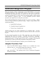
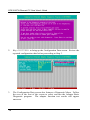
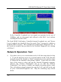
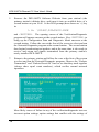
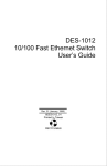
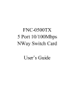
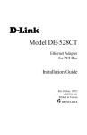
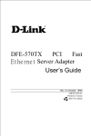
Model DFE-500TX
Fast Ethernet Adapter
for PCI Bus
User’s Guide
Rev. 06 (May, 1997)
6DE-E50-0TX-.06
Printed in Taiwan
RECYCLABLE
Table of Contents
1. INTRODUCTION............................................................ 1
ABOUT FAST ETHERNET............................................. 1
ABOUT AUTONEGOTIATION........................................ 2
ABOUT PCI BUS............................................................ 3
FEATURES .................................................................... 4
2. INSTALLATION............................................................. 7
UNPACK AND INSPECT................................................ 7
INSTALL THE ADAPTER ............................................... 8
CONNECT THE NETWORK CABLE.............................. 9
CONNECTING FOR FAST ETHERNET................... 9
CONNECTING FOR 10MBPS ETHERNET ............ 10
SOFTWARE INSTALLATION....................................... 10
VERIFICATION/DIAGNOSTIC PROGRAM .................. 11
ADAPTER FUNCTION TEST................................. 11
NETWORK OPERATION TEST............................. 13
A. TROUBLESHOOTING................................................. 16
B. SPECIFICATIONS ......................................................... 2
INDEX...........................................................................21
WARRANTY......................................................................22
REGISTRATION................................................................26
1
Introduction
Thank you for choosing D-Link DFE-500TX, the value leader among Fast
Ethernet adapters for PCI−Bus personal computers. This Introduction chapter
will be useful if you are new to Fast Ethernet and other new technology
featured by the DFE-500TX. Otherwise, skip ahead to the Installation chapter.
About Fast Ethernet
Fast Ethernet is a network technology specified by IEEE Standard 802.3. It
extends the traditional 10Mbps Ethernet technology to achieve 100Mbps
transmission and reception, while retaining the same CSMA/CA Ethernet
protocol. Thus while Fast Ethernet provides a tenfold increase in network
capacity, it is wholly compatible with traditional 10Mbps Ethernet network
facilities. This compatibility is the key to easy and efficient upgrades to
100Mbps in your network areas needing greater bandwidth. Upgrading
selected areas to Fast Ethernet does not require hardware or software changes
in network areas where traditional 10Mbps Ethernet is providing good service.
For upgrading existing Ethernet installations to 100Mbps, and especially for
selectively upgrading areas needing upgrade, Fast Ethernet is the clear choice in
terms of cost-effectiveness, as well as convenience and smoothness in
transition.
Fast Ethernet comprises two subtypes: 100Base-T4 and 100Base-TX.
100Base-T4 Fast Ethernet can utilize existing Category 3 or Category 4 UTP
network cabling, but does not provide for full duplex operation. 100Base-TX
requires Category 5 cabling, but does provide full duplex operation. Full duplex
100Base-TX operation allows simultaneous transmission and reception, both at
100Mbps, thus providing service potentially equal to 200Mbps half-duplex
service.
DFE-500TX Ethernet PC Card User's Guide
The DFE-500TX Adapter does not support the 100Base-T4 subtype. To
provide compatibility in traditional 10Mbps Ethernet environments (where, for
example, DFE-500TX adapters are installed anticipating upgrade of supporting
hub equipment to Fast Ethernet), the DFE-500TX also supports traditional
10Mbps Ethernet operation, in full-duplex as well as half-duplex modes.
Selection of the best operation mode in any given installation is automatically
governed by Autonegotiation.
About Autonegotiation
You have probably had the experience of making a dialup connection through a
modem, and have heard the gravelly−sounding exchanges between your
modem and the modem at the other end of the telephone line (these exchanges
are ordinarily played out through a speaker in your local modem). As irritating
as those few seconds of noise may be, they do let you know that your modem
and the remote modem are on the job, preparing for your intended
communication with the remote computer.
The preparatory work of the two modems during those few seconds before you
see the “connect” message is to negotiate the best data communication scheme
which is supported by both modems, and which is suitable for the quality of the
telephone line linkage between them. The parameters to be settled between the
two modems include best baud rate, compression method, and error correction
method. When the two modems have tested the phone-line quality and settled
on the combination of shared options and parameters which will provide the
best data communication over the connecting phone line, then you are given
the “connect” message which signals the end of the intermodem negotiation
and the beginning of your intended communication with the remote computer.
Autonegotiation between devices within an Ethernet LAN is similar in concept,
but much briefer. The two devices involved in the Autonegotiation will be the
DFE-500TX Adapter serving your station (installed in your computer), and the
hub through which it is connected into the LAN. The options to be negotiated
between the DFE-500TX and its supporting hub include Ethernet type
(100BASE-TX Fast Ethernet or 10BASE-T Ethernet) and duplex mode (halfduplex, being one-way-at-a-time, or full duplex, being simultaneous transmitand-receive).
2
DFE-500TX Ethernet PC Card User's Guide
Startup communication between the two devices occurs when both devices are
power-on, the cable connection between them is good, and the Network
Operating System software is running. As soon as those conditions are
satisfied, the preparatory process of Autonegotiation between the DFE-500TX
and its supporting hub proceeds automatically. If the hub has Autonegotiation
functionality, then it and the DFE-500TX exchange a series of messages in
which each device signals its capabilities and listens for corresponding
information about the other. The Autonegotiation process requires only a few
milliseconds, and the two devices select the best communication parameters
supported by both devices.
If the hub does not have Autonegotiation functionality, then its monotone
(single capability) message will be recognized by the DFE-500TX’s
Autonegotiation facility, and the DFE-500TX will simply switch to the one of
its own capabilities which matches that of the hub.
When the preparatory procedure of Autonegotiation is completed, then the line
is ready and will provide a data channel which is optimal for the two devices.
The line will remain ready without further Autonegotiation action until the
linkage is broken. Autonegotiation then reoccurs at any time that the linkage is
restored, again making the line ready for optimal data communications.
About PCI Bus
Your DFE-500TX Adapter delivers outstanding performance by fully
exploiting the advanced features of your computer’s PCI bus. DFE-500TX
Adapters utilize the Bus Master Mode of the PCI bus, allowing direct transfers
of Ethernet packet content between computer memory and the adapter’s
controller, thus minimizing network demand on the CPU. The adapter’s
controller function is implemented by a DEC (Digital Equipment Corporation)
Intelligent Ethernet Controller chip, which provides the additional benefit of
reduced command processing overhead.
The working relationship between a DFE-500TX adapter and main memory
working in Bus Master mode is powered by the Bridge/Memory Controller of
the PCI bus. This reduces the CPU role in network operations, thus freeing the
CPU to service other tasks, with resulting improvement in overall computing
(multitasking) performance. At the same time, it produces superior network
3
DFE-500TX Ethernet PC Card User's Guide
throughput by reducing latency (waiting for CPU service) during transmissions
and receptions.
Features
Designed for versatility and performance, the DFE-500TX Adapter provides
the following features:
• Operates in a PCI Bus Master slot of a Pentium/486 computer,
independent of CPU speed
• PCI Bus Master memory access, for high throughput and low CPU
demand
• Complies with IEEE 802.3 100Base-TX and 10Base-T Ethernet
standards
• Plug and Play installation
• RJ-45 connector for network cable connection
• 100Mbps Fast Ethernet or 10Mbps Ethernet data transfer, selected via
Autonegotiation
• Full duplex or half-duplex operation, selected by Autonegotiation
• Autonegotiation selects interoperation options for compatibility and best
performance
• Built-in FIFO buffers reduce overhead of memory transfers
• Multi-thread operation
• 32-bit memory addressing provides 4GB range
• VLSI components provide high reliability, low power consumption and
reduced card size
4
DFE-500TX Ethernet PC Card User's Guide
• Five LED indicators: 100Mbps/10Mbps, Full/Half Duplex, Link, Active,
and Collision
• Drivers for all leading Network Operating Systems
5
2
Installation
Installation of a DFE-500TX Ethernet Adapter requires hardware installation
first, then software installation.
Unpack and Inspect
CAUTION:
Under ordinary circumstances, a DFE-500TX card
will not be affected by static charge as may be
received through your body during handling of the
unit. In special circumstances where you may carry
an extraordinarily high static charge, it is good
practice to reduce the charge by touching a ground
before handling the adapter card.
Open the shipping carton and carefully remove all items. In addition to this
User's Guide, ascertain that you have:
• One DFE-500TX Ethernet Adapter Card
• One 3.5" diskette: DFE-500TX Software Diskette
If your order included the Boot ROM option, then you should also have,
separately packaged, one Boot ROM Chip. In the event that you find any
mismatch, damage or missing item, promptly contact your dealer for correction.
DFE-500TX Ethernet PC Card User's Guide
Install the Adapter
1.
Shut down the computer, unplug its power cord, and remove the chassis
cover.
2.
If your order does not include the Boot ROM option, go ahead to Step 3.
If your order includes the Boot ROM option, then install the Boot ROM
Chip by plugging the chip into the Boot ROM Socket on the DFE-500TX
card. The notched end of the Boot ROM Chip must be aligned with the
notched end of the Boot ROM Socket (opposite alignment will cause
destruction of the Boot ROM Chip).
3.
Insert the contact edge of the DFE-500TX card into the connector of any
available PCI Bus Master expansion slot. Press the card firmly into the
connector to ascertain that the card’s contacts are fully seated in the
connector.
4.
Install the bracket screw which secures the card to the computer chassis.
5.
Replace the computer’s chassis cover.
6.
Reconnect the computer’s power cord, and switch computer power on. If
the BIOS section of your computer’s boot program is Plug and Play
compliant, then at power-up the BIOS will automatically configure any
newly installed DFE-500TX adapter.
NOTE: Due to a fault in some Plug-n-Play BIOS programs, it
happens occasionally that a newly installed adapter is
assigned an Interrupt Number which is already assigned to
another device. In such a case, the conflict of Interrupt
Number will cause faults in the behavior of both devices.
Then it is necessary to run the CMOS Setup utility, and
manually assign a non-conflicting Interrupt Number.
8
DFE-500TX Ethernet PC Card User's Guide
Connect the Network Cable
Category 5 UTP cable is good enough to qualify under both the Fast Ethernet
cabling rules and the traditional Ethernet cabling rules. The maximum
individual cable run between any station and its supporting hub is 100m. The
maximum individual cable run joining two hubs is 10m in general, but is 100m
when both hubs qualify as Ethernet Class 2 Repeaters (all D-Link Ethernet
hubs do qualify). But these cable runs may need to be shorter than the given
individual maximum lengths, because their lengths are also restricted by the
rule that the maximum aggregated cable run between any two stations is
205m.
Connecting for Fast Ethernet
Category 5 UTP cable is required for Fast Ethernet operation. The maximum
cable run between the DFE-500TX and the supporting hub is 300 ft. The cable
must be “straight” (not a “crossover” cable), with an RJ-45 plug at each end.
Make the network connection by plugging one end of the cable into the RJ-45
receptacle of the DFE-500TX, and the other end into a port of the supporting
hub.
graphic from 2-4 top
9
DFE-500TX Ethernet PC Card User's Guide
Connecting for 10Mbps Ethernet
Category 3, Category 4, and Category 5 UTP cable, as well as EIA/TIA - 568
100-ohm STP cable, all qualify under Ethernet cabling rules. The maximum
cable run between the DFE-500TX and the supporting hub is 300 ft. The cable
must be “straight” (not a “crossover” cable) with RJ-45 plug at each end.
Make the network connection by plugging one end of the cable into the RJ-45
receptacle of the DFE-500TX, and the other end into a port of the supporting
hub.
graphic from p. 2-3
Software Installation
On account of the great variety of network environments in which the DFE500TX may be installed and used, and the frequency of revisions in those
network systems, the instructions for software installation are given as
README files on the DFE-500TX Software Diskette. Review the root
directory README for overview information, then for full installation details,
see the README and referenced instruction files in the subdirectory
appropriate to your network operating system.
10
DFE-500TX Ethernet PC Card User's Guide
Verification/Diagnostic Program
This test program verifies configuration of the DFE-500TX as set by the
installation procedure, and assists with isolation of any faults in operation.
Verification and testing procedures are optional, and will only be useful in the
unusual event that there is a fault, such as an interrupt number conflict among
your computer’s expansion cards. If your installation provides normal
operation, you might choose to skip these procedures.
The Verification/Diagnostic Program provides two levels of testing: adapter
function testing and network operation testing. Adapter testing includes three
separate procedures:
a. Serial ROM Verification
b. Controller Internal Loopback test
c. Twister Layer Loopback test
Adapter testing does not require substitution of a loopback cable. All three
parts of the Adapter test may be carried out with the network cable connection
in place.
For the network operation test, the cable connecting your station with its
supporting hub must be in place. Network test involves “broadcast”
transmission of test packets from the primary station. The test cannot be fully
implemented unless a second station on the LAN is available to the network
operation test, in order to return the test packets to the primary station.
To run the Verification/Diagnostic Program, proceed with these steps:
Adapter Function Test
1.
Insert the DFE-500TX Software Diskette in an available drive (here
shown as drive A). At the DOS prompt (here shown as >), key in:
> A: \DIAG\DIAG500.EXE
and <RETURN>. The opening screen of the Verification/ Diagnostic
program will appear.
11
DFE-500TX Ethernet PC Card User's Guide
2.
Key <RETURN> to bring up the Configuration Data screen. Review the
reported configuration data before proceeding to Step 3.
3.
The Configuration Data screen also features a Diagnostic Menu. Follow
the cues at the foot of the screen to select and run the Adapter Basic
Diagnostic program. The adapter function test results will appear
onscreen.
12
DFE-500TX Ethernet PC Card User's Guide
In the Controller Loopback test, test signals are generated at the rate of
100Mbps, and are intercepted and reflected at the MAC level without
reaching the network cable.
The Serial ROM Verification, Controller Internal Loopback test, and Twister
Layer Loopback test should all show the result “Pass,” irrespective whether a
loopback cable is in place. This concludes the Adapter Basic Diagnostic test. If
the results are normal, then go ahead to the Network Diagnostic test, starting
with Step 4.
Network Operation Test
4.
13
If you have access to a second station on the LAN, then skip ahead to Step
5. If you do not have access to a second station on the LAN, then the
network test will be limited to “blind” transmission of test packets (none
of which will be returned to the primary station). Follow the cues at the
foot of the screen to select and run the Network Diagnostic program.
Observe the “Packets Transmitted” line to see that the “Packets
Transmitted” line reports a steadily and rapidly increasing packet count.
This will indicate normal transmission onto the LAN, and will be the end
of your Verification/Diagnostic run. Skip the remaining steps shown
below.
DFE-500TX Ethernet PC Card User's Guide
5.
Remove the DFE-500TX Software Diskette from your station's (the
primary station's) diskette drive, and insert it into an available drive of a
second station on your LAN. At the DOS prompt (here shown as >), key
in:
> A: \DIAG\DIAG500.EXE
and <RETURN>. The opening screen of the Verification/Diagnostic
program will appear onscreen at the second station. Key <RETURN> to
bring up the Configuration Data and Diagnostic Menu onscreen at the
second station. Follow the cues at the foot of the screen to select and run
the Network Diagnostic program at the second station. The second station
then begins broadcasting test packets, and at the same time is also ready to
receive and return test signals transmitted from the primary station’s
newly installed DFE-500TX.
7.
Return to the primary station and follow the cues at the foot of the screen
to select and run the Network Diagnostic program. Observe the “Packets
Transmitted” and “Packets Received” lines to see that they track together
(always show equal count numbers), which verifies normal network
operation.
Hiya, Normal!
Hiya, Heading 1!
Hiya, Heading 2!
Most likely causes of failure in any of the verification/diagnostic tests are
incorrect option settings, option settings that conflict with the settings of
14
DFE-500TX Ethernet PC Card User's Guide
other boards, or improper installation. In the event that any of the
verification/diagnostic tests fails, review the following troubleshooting list.
1.
Ascertain that the adapter card is fully and firmly seated in the slot
connector.
2.
Check the length and rating of connecting cables.
3.
Ascertain that the adapter’s PCI slot is not deactivated at the BIOS level.
The CMOS Setup utility in PCI computers ordinarily provides the option
to activate or deactivate PCI slots.
4.
Replace the adapter in question with a verified adapter and run the
diagnostic test again.
5.
Install the questioned adapter in another PCI computer and run the tests
again.
6.
Remove all other PCI adapters from the computer and run the tests again.
If the verification/diagnostic run is then normal, then there is probably an
interrupt number conflict which will have to be resolved manually by a
CMOS Setup utility run after you have reinstalled all of the expansion
cards.
15
A
Troubleshooting
If you experience any problems with the adapter, first ascertain that the
appropriate driver is loaded, that the proper grade of cable is employed for the
network connection, and that the supporting hub is properly qualified for the
application (such as 10BASE-T or 100Base-TX).
The DFE-500TX Adapter features five LED indicators:
• 100Mbps/10Mbps SPEED SELECTION
This LED shows steady green when 100Mbps speed is selected. It is dark
(off) when 10Mbps is selected.
• FULL/HALF DUPLEX SELECTION
Steady green indicates Full Duplex operation selected. Dark when Half
Duplex operation is selected.
• LINK
Steady green indicates good linkage between the DFE-500TX and its
supporting hub.
• ACTIVE
Flashing green indicates that the adapter is transmitting or receiving.
• COLLISION
Intermittent yellow indicates data collisions the network.
flashing of the collision LED is normal.
Intermittent
B
DFE-500TX Ethernet PC Card User's Guide
Specifications
Network Type:
• Ethernet 100Base-TX
Ethernet IEEE 802.3u standard for 100Mbps baseband CSMA/CD local
area network
• Ethernet 10BASE-T
Ethernet IEEE 802.3 standard for 10Mbps baseband CSMA/CD local
area network
Jumperless Hardware
Autonegotiation functionality
Media interface: RJ-45
LAN Chip Set:
• Interface controller,
DEC DC21140
• Transceiver interface, LTX970
EMI Certifications:
FCC Class B
VCCI Class 2
CISPR B
Canada ICES-003, Class B
CE Certification
Host interface: PCI Bus (Bus Master)
I/O base address assigned by Plug and Play system
Interrupt Number Assigned by Plug and Play system
Physical Dimensions: 13.91 cm x 7.9 cm
Environment:
Storage:
−20° to 80°C, (4° to 176° F)
DFE-500TX Ethernet PC Card User's Guide
Operating:
Humidity:
0° to 55° C, (32° to 131° F)
10% to 90% non-condensing
Power Consumption: 1.05W (Max.)
PCB Layer: 4 layers
Device Drivers*
•
• Novell Netware 3.x and
driver
•
• NDIS driver
D-Link TCP/IP for DOS
4.x ODI
• MS LAN Manager
• WIN/TCP Pathway
Packet driver
Access for DOS
•
FTP PC/TCP
• SCO UNIX
•
SUN PC-NFS
• IBM LAN Server
•
3COM 3+Share
• DEC Path Works
•
NetBIOS Driver
• Banyan VINES
•
WINDOWS NT
•
Windows NT Advanced
•
Windows 95
• AT&T UNIX
•
SCO Open Server
• Solaris UNIX
•
Winsock
• NCSA
*Check http://www.dlink.com for newest
releases of drivers.
• 3COM 3+Open
Server
• IBM PC LAN Support
Program
Index
100Mbps/10Mbps LED, 6; 18
10Mbps Ethernet, 1; 2; 5; 10
DFE-500TX Ethernet PC Card User's Guide
Active LED, 6; 18
Fast Ethernet, 1 - 3; 5; 9
autonegotiation, 2 - 4; 5; 19
Full/Half Duplex LED, 6; 18
BIOS Program, 8; 17
hub, autonegotiation
function, 3 - 4
Boot ROM, 7; 8
cabling, 2; 3; 5; 9; 10; 12; 15;
17; 18
latency, 5
CMOS Setup, 9; 17
Link LED 6; 18
Collision LED, 6; 18
Loopback tests, 12; 15
communication parameters, 4
network operating system,
11; 20
DFE-500TX Software
Diskette, 7; 15
LED indicators, 6; 18
PCI Bus, 4; 5; 8; 19
D-Link WWW Server, 20
README files, 11
Driver programs, 20
second station, 12; 15; 16
Ethernet standards, 5; 19
Software upgrades, 20
expansion slot, 8
static charge, 7
2
Error! Style not defined.
Offices
U.S.A.
D-LINK SYSTEMS, INC.
5 Musick Irvine, CA 92618 USA
TEL: 1-714-455-1688 FAX: 1-714-455-2521
CANADA
D-LINK CANADA, INC.
2180 Dunwin Drive, Unit # 6,
Mississauga Ontario, L5L 5M8, Canada
TEL: 1-905-828-0260 FAX: 1-905-828-5669
U.K.
D-LINK (EUROPE) LTD.
D-Link House, 6 Garland Road, Stanmore, London HA7 1DP U.K.
TEL: 44-181-235-5555 FAX: 44-181-235-5500
GERMANY D-LINK (DEUTSCHLAND) GMBH I.G.
Bachstraße 2265812 65830 Kriftel, Germany
TEL: 49-6192-97110 FAX: 49-6192-971111
FRANCE
D-LINK FRANCE
Le FLORILEGE #2, Allee de la Fresnerie
78330 Fontenay Le Fleury France
TEL: 33-1-30238688 FAX: 33-1-30238689
SWEDEN
D-LINK A/B
World Trade Center P. O. Box 70396, 107 24 Stockholm Sweden
TEL: 46-8-700.62.11 FAX: 46-8-21.96.40
DENMARK D-LINK DENMARK
Naverland 2 DK-2600 Glostrup Copenhagen, Denmark
TEL: 45-43-96.90.40 FAX: 45-43-42.43.47
SINGAPORE
D-LINK SINGAPORE PTE.LTD.
77 Science Park Drive #03-03 CINTECH III,
Singapore Science Park Singapore 118256
TEL : 65-774-6233 FAX: 65-774-6322
AUSTRALIA
D-LINK AUSTRALIA PTY.LTD.
Unit 16, 390 Eastern Valley Way Roseville, NSW 2069 Australia
TEL: 61-2-9417-7100 FAX: 61-2-9417-1077
CHINA
D-LINK BEIJING
15th Floor, Science and Technology Tower
No. 11, Baishiqiao Road, Haidian District, Beijing 100081 China
TEL: 86-10-68467106/68467107/68467108/68467109 FAX: 86-10-68467110
JAPAN
D-LINK TOKYO
5F, 3-9-1 Togoshi, Shinagawa-ku Tokyo 142 Japan
TEL: 81-3-5751-2351 FAX: 81-3-5751-2352
INDIA
D-LINK (INDIA) PVT. LTD.
Plot No.5, Kurla-Bandra Complex Rd.
Off Cst Rd., Santacruz (E) Bombay - 400 098 India
TEL: 91-22-611-2788/617-2478-80/611-2948 FAX: 91-22-611-3503/617-2476
TAIWAN
D-LINK TAIWAN
2F, No.233-2 Pao-Chiao Rd, Hsin-Tien, Taipei,Taiwan, R.O.C.
TEL: 886-2-916-1600 FAX: 886-2-914-6299
Subject to the terms and conditions set forth herein, D-Link Systems, Inc. (“D-Link”)
provides this Limited Warranty:
•
•
Only to the person or entity that originally purchased the product from D-Link or its
authorized reseller or distributor, and
Only for products purchased and delivered within the fifty states of the United States,
the District of Columbia, U.S. Possessions or Protectorates, U.S. Military
Installations, or addresses with an APO or FPO.
Limited Warranty: D-Link warrants that the hardware portion of the D-Link product
described below (“Hardware”) will be free from material defects in workmanship and
materials under normal use from the date of original retail purchase of the product, for the
period set forth below (“Warranty Period”), except as otherwise stated herein.
•
•
•
Hardware (excluding power supplies and fans): One (1) year
Power supplies and fans: One (1) year
Spare parts and spare kits: Ninety (90) days
The customer's sole and exclusive remedy and the entire liability of D-Link and its
suppliers under this Limited Warranty will be, at D-Link’s option, to repair or replace the
defective Hardware during the Warranty Period at no charge to the original owner or to
refund the actual purchase price paid. Any repair or replacement will be rendered by DLink at an Authorized D-Link Service Office. The replacement hardware need not be new
or have an identical make, model or part. D-Link may, at its option, replace the defective
Hardware or any part thereof with any reconditioned product that D-Link reasonably
determines is substantially equivalent (or superior) in all material respects to the defective
Hardware. Repaired or replacement hardware will be warranted for the remainder of the
original Warranty Period or ninety (90) days, whichever is longer, and is subject to the
same limitations and exclusions. If a material defect is incapable of correction, or if D-Link
determines that it is not practical to repair or replace the defective Hardware, the actual
price paid by the original purchaser for the defective Hardware will be refunded by D-Link
upon return to D-Link of the defective Hardware. All Hardware or part thereof that is
replaced by D-Link, or for which the purchase price is refunded, shall become the property
of D-Link upon replacement or refund.
Limited Software Warranty: D-Link warrants that the software portion of the product
(“Software”) will substantially conform to D-Link’s then current functional specifications for
the Software, as set forth in the applicable documentation, from the date of original retail
purchase of the Software for a period of ninety (90) days (“Software Warranty Period”),
provided that the Software is properly installed on approved hardware and operated as
contemplated in its documentation. D-Link further warrants that, during the Software
Warranty Period, the magnetic media on which D-Link delivers the Software will be free of
physical defects. The customer's sole and exclusive remedy and the entire liability of DLink and its suppliers under this Limited Warranty will be, at D-Link’s option, to replace the
non-conforming Software (or defective media) with software that substantially conforms to
D-Link’s functional specifications for the Software or to refund the portion of the actual
purchase price paid that is attributable to the Software. Except as otherwise agreed by D-
Link in writing, the replacement Software is provided only to the original licensee, and is
subject to the terms and conditions of the license granted by D-Link for the Software.
Replacement Software will be warranted for the remainder of the original Warranty Period
and is subject to the same limitations and exclusions. If a material non-conformance is
incapable of correction, or if D-Link determines in its sole discretion that it is not practical
to replace the non-conforming Software, the price paid by the original licensee for the
non-conforming Software will be refunded by D-Link; provided that the non-conforming
Software (and all copies thereof) is first returned to D-Link. The license granted
respecting any Software for which a refund is given automatically terminates.
Non-Applicability of Warranty: The Limited Warranty provided hereunder for Hardware
and Software portions of D-Link's products will not be applied to and does not cover any
refurbished product and any product purchased through the inventory clearance or
liquidation sale or other sales in which D-Link, the sellers, or the liquidators expressly
disclaim their warranty obligation pertaining to the product and in that case, the product is
being sold "As-Is" without any warranty whatsoever including, without limitation, the
Limited Warranty as described herein, notwithstanding anything stated herein to the
contrary.
Submitting A Claim: The customer shall return the product to the original purchase point
based on its return policy. In case the return policy period has expired and the product is
within warranty, the customer shall submit a claim to D-Link as outlined below:
•
The customer must submit with the product as part of the claim a written description
of the Hardware defect or Software nonconformance in sufficient detail to allow DLink to confirm the same, along with proof of purchase of the product (such as a copy
of the dated purchase invoice for the product) if the product is not registered.
•
The customer must obtain a Case ID Number from D-Link Technical Support at 1877-453-5465, who will attempt to assist the customer in resolving any suspected
defects with the product. If the product is considered defective, the customer must
obtain a Return Material Authorization (“RMA”) number by completing the RMA form
and entering the assigned Case ID Number at https://rma.dlink.com/.
•
After an RMA number is issued, the defective product must be packaged securely in
the original or other suitable shipping package to ensure that it will not be damaged
in transit, and the RMA number must be prominently marked on the outside of the
package. Do not include any manuals or accessories in the shipping package. DLink will only replace the defective portion of the product and will not ship back any
accessories.
•
The customer is responsible for all in-bound shipping charges to D-Link. No Cash on
Delivery (“COD”) is allowed. Products sent COD will either be rejected by D-Link or
become the property of D-Link. Products shall be fully insured by the customer and
shipped to D-Link Systems, Inc., 17595 Mt. Herrmann, Fountain Valley, CA
92708. D-Link will not be held responsible for any packages that are lost in transit to
D-Link. The repaired or replaced packages will be shipped to the customer via UPS
Ground or any common carrier selected by D-Link. Return shipping charges shall be
prepaid by D-Link if you use an address in the United States, otherwise we will ship
the product to you freight collect. Expedited shipping is available upon request and
provided shipping charges are prepaid by the customer.
D-Link may reject or return any product that is not packaged and shipped in strict
compliance with the foregoing requirements, or for which an RMA number is not visible
from the outside of the package. The product owner agrees to pay D-Link’s reasonable
handling and return shipping charges for any product that is not packaged and shipped in
accordance with the foregoing requirements, or that is determined by D-Link not to be
defective or non-conforming.
What Is Not Covered: The Limited Warranty provided herein by D-Link does not cover:
Products that, in D-Link’s judgment, have been subjected to abuse, accident, alteration,
modification, tampering, negligence, misuse, faulty installation, lack of reasonable care,
repair or service in any way that is not contemplated in the documentation for the product,
or if the model or serial number has been altered, tampered with, defaced or removed;
Initial installation, installation and removal of the product for repair, and shipping costs;
Operational adjustments covered in the operating manual for the product, and normal
maintenance; Damage that occurs in shipment, due to act of God, failures due to power
surge, and cosmetic damage; Any hardware, software, firmware or other products or
services provided by anyone other than D-Link; and Products that have been purchased
from inventory clearance or liquidation sales or other sales in which D-Link, the sellers, or
the liquidators expressly disclaim their warranty obligation pertaining to the product.
While necessary maintenance or repairs on your Product can be performed by any
company, we recommend that you use only an Authorized D-Link Service Office.
Improper or incorrectly performed maintenance or repair voids this Limited Warranty.
Disclaimer of Other Warranties: EXCEPT FOR THE LIMITED WARRANTY SPECIFIED
HEREIN, THE PRODUCT IS PROVIDED “AS-IS” WITHOUT ANY WARRANTY OF ANY
KIND WHATSOEVER INCLUDING, WITHOUT LIMITATION, ANY WARRANTY OF
MERCHANTABILITY, FITNESS FOR A PARTICULAR PURPOSE AND NONINFRINGEMENT. IF ANY IMPLIED WARRANTY CANNOT BE DISCLAIMED IN ANY
TERRITORY WHERE A PRODUCT IS SOLD, THE DURATION OF SUCH IMPLIED
WARRANTY SHALL BE LIMITED TO THE DURATION OF THE APPLICABLE
WARRANTY PERIOD SET FORTH ABOVE. EXCEPT AS EXPRESSLY COVERED
UNDER THE LIMITED WARRANTY PROVIDED HEREIN, THE ENTIRE RISK AS TO
THE QUALITY, SELECTION AND PERFORMANCE OF THE PRODUCT IS WITH THE
PURCHASER OF THE PRODUCT.
Limitation of Liability: TO THE MAXIMUM EXTENT PERMITTED BY LAW, D-LINK IS
NOT LIABLE UNDER ANY CONTRACT, NEGLIGENCE, STRICT LIABILITY OR OTHER
LEGAL OR EQUITABLE THEORY FOR ANY LOSS OF USE OF THE PRODUCT,
INCONVENIENCE OR DAMAGES OF ANY CHARACTER, WHETHER DIRECT,
SPECIAL, INCIDENTAL OR CONSEQUENTIAL (INCLUDING, BUT NOT LIMITED TO,
DAMAGES FOR LOSS OF GOODWILL, LOSS OF REVENUE OR PROFIT, WORK
STOPPAGE, COMPUTER FAILURE OR MALFUNCTION, FAILURE OF OTHER
EQUIPMENT OR COMPUTER PROGRAMS TO WHICH D-LINK’S PRODUCT IS
CONNECTED WITH, LOSS OF INFORMATION OR DATA CONTAINED IN, STORED
ON, OR INTEGRATED WITH ANY PRODUCT RETURNED TO D-LINK FOR
WARRANTY SERVICE) RESULTING FROM THE USE OF THE PRODUCT, RELATING
TO WARRANTY SERVICE, OR ARISING OUT OF ANY BREACH OF THIS LIMITED
WARRANTY, EVEN IF D-LINK HAS BEEN ADVISED OF THE POSSIBILITY OF SUCH
DAMAGES. THE SOLE REMEDY FOR A BREACH OF THE FOREGOING LIMITED
WARRANTY IS REPAIR, REPLACEMENT OR REFUND OF THE DEFECTIVE OR NONCONFORMING PRODUCT. THE MAXIMUM LIABILITY OF D-LINK UNDER THIS
WARRANTY IS LIMITED TO THE PURCHASE PRICE OF THE PRODUCT COVERED
BY THE WARRANTY. THE FOREGOING EXPRESS WRITTEN WARRANTIES AND
REMEDIES ARE EXCLUSIVE AND ARE IN LIEU OF ANY OTHER WARRANTIES OR
REMEDIES, EXPRESS, IMPLIED OR STATUTORY.
Governing Law: This Limited Warranty shall be governed by the laws of the State of
California. Some states do not allow exclusion or limitation of incidental or consequential
damages, or limitations on how long an implied warranty lasts, so the foregoing limitations
and exclusions may not apply. This Limited Warranty provides specific legal rights and
you may also have other rights which vary from state to state.
Trademarks: D-Link is a registered trademark of D-Link Systems, Inc. Other trademarks
or registered trademarks are the property of their respective owners.
Copyright Statement: No part of this publication or documentation accompanying this
product may be reproduced in any form or by any means or used to make any derivative
such as translation, transformation, or adaptation without permission from D-Link
Corporation/D-Link Systems, Inc., as stipulated by the United States Copyright Act of
1976 and any amendments thereto. Contents are subject to change without prior notice.
Copyright 2005 by D-Link Corporation/D-Link Systems, Inc. All rights reserved.
CE Mark Warning: This is a Class B product. In a domestic environment, this product
may cause radio interference, in which case the user may be required to take adequate
measures.
FCC Statement: This equipment has been tested and found to comply with the limits for
a Class B digital device, pursuant to part 15 of the FCC Rules. These limits are designed
to provide reasonable protection against harmful interference in a residential installation.
This equipment generates, uses, and can radiate radio frequency energy and, if not
installed and used in accordance with the instructions, may cause harmful interference to
radio communication. However, there is no guarantee that interference will not occur in a
particular installation. If this equipment does cause harmful interference to radio or
television reception, which can be determined by turning the equipment off and on, the
user is encouraged to try to correct the interference by one or more of the following
measures:
•
•
•
•
Reorient or relocate the receiving antenna.
Increase the separation between the equipment and receiver.
Connect the equipment into an outlet on a circuit different from that to which the
receiver is connected.
Consult the dealer or an experienced radio/TV technician for help.
For detailed warranty information applicable to products purchased outside
the United States, please contact the corresponding local D-Link office.
Registration
Product registration is entirely voluntary and failure to complete or
return this form will not diminish your warranty rights.