1
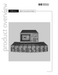
CYS25G0101DX-ATC Evaluation Board
User’s Guide
Cypress Semiconductor Corporation
•
3901 North First Street
•
San Jose
•
CA 95134
•
408-943-2600
March 19, 2002
[+] Feedback
CYS25G0101DX-ATC Evaluation Board User’s Guide
Table of Contents
1. Introduction ....................................................................................................................................... 4
2. Features ............................................................................................................................................. 4
3. Kit Contents ...................................................................................................................................... 4
4. Functional Description ..................................................................................................................... 4
5. Diagnostic Modes ........................................................................................................................... 12
5.1 Diagnostic Loopback Mode ..................................................................................................... 12
5.2 Line Loopback ........................................................................................................................... 13
5.3 Analog Line Loopback .............................................................................................................. 14
5.4 “Parallel Line Loopback” (TEST0) Mode ................................................................................ 15
5.4.1 Test the Internal RX CDR PLL Only ................................................................................ 15
5.4.2 Test the Internal RX CDR PLL and TX PLL .................................................................... 15
6. Testing Hookup ............................................................................................................................... 16
6.1 Set-up for BERT Test ................................................................................................................ 16
6.2 Set-up for Eye Diagram Test .................................................................................................... 17
6.3 SONET Jitter Transfer and Jitter Tolerance Test ................................................................... 18
6.4 Set-up for Testing the TX PLL in Parallel Line Loopback Mode ........................................... 19
7. Eye Diagram Testing Result .......................................................................................................... 20
8. Jitter Transfer Testing Result ........................................................................................................ 21
9. Jitter Tolerance Testing Result ..................................................................................................... 22
10. Schematic Diagram, PCB Layout and BOM (Bill of Material) ................................................... 23
Appendix A: Schematic Diagrams of the CYS25G0101DX Evaluation Board ............................... 24
Appendix B: PCB Layout Diagrams of the CYS25G0101DX Evaluation Board ............................ 32
Appendix C: CYS25G0101DX Evaluation Board LVPECL BOM (Bill of Material) ......................... 42
Appendix D: CYS25G0101DX Evaluation Board HSTL BOM (Bill of Material) .............................. 47
List of Figures
Figure 1. The Block Diagram of the CYS25G0101DX ......................................................................... 5
Figure 2. The CYS25G0101DX Evaluation Board ................................................................................ 6
Figure 3. The Jumper Orientations of the CYS25G0101DX ............................................................. 11
Figure 4. Diagnostic Loopback Mode Data Path .............................................................................. 12
Figure 5. Line Loopback Mode Data Path ......................................................................................... 13
Figure 6. Analog Line Loopback Mode Data Path ............................................................................ 14
Figure 7. Parallel Loopback (TEST0) Mode Data Path ..................................................................... 15
Figure 8. Equipment Set-up for BERT Test ....................................................................................... 16
Figure 9. Equipment Set-up For Eye Diagram Test .......................................................................... 17
Figure 10. Equipment Set-up For Jitter Test ..................................................................................... 18
Figure 11. Equipment Set-up For Testing the TX PLL in Parallel Line Loopback Mode ............... 19
Figure 12. CYS25G0101DX Evaluation Board Eye Diagram ............................................................ 20
Figure 13. CYS25G0101DX Evaluation Board GR-253 Jitter Transfer Testing Result .................. 21
Figure 14. CYS25G0101DX Evaluation Board G958 Jitter Transfer Testing Result ...................... 21
Figure 15. CYS25G0101DX Evaluation Board GR-253 JitterTolerance Testing Result ................. 22
Figure 16. CYS25G0101DX Evaluation Board G825 Jitter Tolerance Testing Result .................... 22
Figure 17. Top Level of CYS25G0101DX Evaluation Board Schematic Diagram ......................... 25
Figure 18. Parallel Output Block Schematic Diagram ...................................................................... 26
Figure 19. Parallel Input Block Schematic Diagram ......................................................................... 27
Figure 20. Signals Block Schematic Diagram ................................................................................... 28
Figure 21. Power Supply Block Schematic Diagram ........................................................................ 29
Figure 22. Control Block Schematic Diagram ................................................................................... 30
2
[+] Feedback
CYS25G0101DX-ATC Evaluation Board User’s Guide
List of Figures (continued)
Figure 23. Reference Clock Block Schematic Diagram ................................................................... 31
Figure 24. CYS25G0101DX Evaluation Board PCB Mechanical Drawing ....................................... 33
Figure 25. CYS25G0101DX Evaluation Board PCB Top Layer Silk Screen .................................... 34
Figure 26. CYS25G0101DX Evaluation Board PCB Top Layer Layout ........................................... 35
Figure 27. CYS25G0101DX Evaluation Board PCB Top Layer Solder Mask .................................. 36
Figure 28. CYS25G0101DX Evaluation Board PCB Power Plane Layout ....................................... 37
Figure 29. CYS25G0101DX Evaluation Board PCB Ground Plane Layout ..................................... 38
Figure 30. CYS25G0101DX Evaluation Board PCB Bottom Silk Screen ........................................ 39
Figure 31. CYS25G0101DX Evaluation Board PCB Bottom Layer Layout ..................................... 40
Figure 32. CYS25G0101DX Evaluation Board PCB Bottom Solder Mask ....................................... 41
List of Tables
Table 1. Functional Description of the Connectors ............................................................................ 6
Table 2. Pin Assignment of J1 Header and Description of J10 Header ............................................ 7
Table 3. Pin Assignment of J2 Header and Description of J9 Header .............................................. 8
Table 4. Functional Description of DIP Switch 1 (SW1) ..................................................................... 9
Table 5. Functional Description of J4 Connector ............................................................................. 10
Table 6. Description of LED Indicators .............................................................................................. 10
Table 7. Operation Specification of CYS25G0101DX Evaluation Board ......................................... 23
Table 8. CYS25G0101DX Evaluation Board LVPECL BOM - Page 1 of 4 ........................................ 43
Table 9. CYS25G0101DX Evaluation Board LVPECL BOM - Page 2 of 4 ........................................ 44
Table 10. CYS25G0101DX Evaluation Board LVPECL BOM - Page 3 of 4 ..................................... 45
Table 11. CYS25G0101DX Evaluation Board LVPECL BOM - Page 4 of 4 ..................................... 46
Table 12. CYS25G0101DX Evaluation Board HSTL BOM - Page 1 of 4 .......................................... 48
Table 13. CYS25G0101DX Evaluation Board HSTL BOM - Page 2 of 4 .......................................... 49
Table 14. CYS25G0101DX Evaluation Board HSTL BOM - Page 3 of 4 .......................................... 50
Table 15. CYS25G0101DX Evaluation Board HSTL BOM - Page 4 of 4 .......................................... 51
3
[+] Feedback
CYS25G0101DX-ATC Evaluation Board User’s Guide
1. Introduction
Cypress's CYS25G0101DX SONET OC-48 Transceiver is a communications building block for high-speed SONET data communications. It provides complete parallel-to-serial and serial-to-parallel conversions, clock generation, and clock and data recovery operations in a single chip, optimized for full SONET/SDH compliance. The CYS25G0101DX Evaluation Board is designed for evaluating as
well as understanding the characteristics of the CYS25G0101DX SONET/SDH Transceiver. The CYS25G0101DX SONET/SDH
Transceiver Evaluation Board provides the following advantages.
2. Features
• Flexible and easy to operate
• On-board Cypress 120-pin TQFP CYS25G0101DX SONET/SDH Transceiver
• Supports LVPECL and HSTL interfaces
• Dip switch for selecting different diagnostic modes
• Four diagnostic modes – Diagnostic Loopback mode, Line Loopback mode, Analog Line Loopback mode, and factory TEST0
(Parallel Line Loopback) mode
• LFI and FIFO_ERR LEDs
• Onboard oscillator for the REFCLK
• Supports external clock source for the REFCLK
• 16-bit RxD, 16-bit TxD bus, RXCLK, TXCLKI, TXCLKO interface
• SMA connectors for CML input and output buffers
• Separate Banana Jacks for all voltage sources for measuring current individually
3. Kit Contents
• CYS25G0101DX Evaluation Board
• Certificate of Compliance
• CYS25G0101DX Evaluation Kit CD
—
Users Guide
—
Application Notes
— Data Sheet
4. Functional Description
This board can be used to test the CYS25G0101DX in various modes, such as TEST0 (parallel line loopback mode), LINELOOP,
LOOPA and LOOPTIME. The REFCLK of the CYS25G0101DX is connected to the onboard 155.52-MHz oscillator. The on-board
REFCLK can be replaced by connecting the external reference clock source to J17 and J18. To use the external reference clock
source, the C400 and C401 (0.01-µF cap) have to be removed and placed on C402 and C403 positions. Also, the P2, CLKVCC, has to
be disconnected from the power supply (or power down). The CYS25G0101DX Evaluation Board provides an optional optical module
interface for connecting to an optical module daughter card.
The block diagram of the CYS25G0101DX is shown in Figure 1. The detailed functional description can be found in the
CYS25G0101DX data sheet. Figure 2 shows the picture of the CYS25G0101DX Evaluation Board and the location of the jumpers.
Table 1 is the description of all jumpers and connectors. The bus connectors, J1 and J2, are used to connect to the 16-bit RxD and TxD
buses for transferring and receiving the parallel data. Table 2 and Table 3 are the pin definitions of J1 and J2. A multi-function eight-position Dip switch provides the selection of the different diagnostic modes as well as the control functions. Table 4 is the functional description of the Dip switch SW1. The TEST0 jumper, J6, when closed, is used to enable the factory TEST0 (Parallel Line Loop Back)
mode. In the “Parallel Line Loop Back” mode, parallel output buffers are internally jumped to the parallel input buffers. There is no need
to use external jumpers for the headers. J13, J14, J15, J16 and J4 are Differential CML input and output and power supply for the optional optical module daughter card. Table 5 idescribes the optical module interface and Table 6 idescribes the LED. Figure 3 shows the
jumper orientations of the CYS25G0101DX Evaluation Board.
4
[+] Feedback
CYS25G0101DX-ATC Evaluation Board User’s Guide
(155.52MHz)
FIFO_RST TXCLKI
FIFO_ERR
TXD
15:0
(155.52MHz)
REFCLK
TXCLKO
(155.52MHz)
RXCLKOUT
RXD
15:0
Output
Register
Input
Register
TX PLL
x16
FIFO
(5byte)
SHIFTER
Recovered
Bit-Clock
/16
SHIFTER
/16
RX CDR
PLL
Tx Bit-Clock
Lock-to-Ref
LOOPTIME
Retimed
Data
DIAGLOOP
LINELOOP
LOOPA
Lock-to-Data /
Clock Control
Logic
OUT±
PWRDN LOCKREF SD
LFI
RESET
IN±
Figure 1. The Block Diagram of the CYS25G0101DX
5
[+] Feedback
CYS25G0101DX-ATC Evaluation Board User’s Guide
SMA13
SMA14
SMA16
SMA15
J4
P4
SW1
J5
SMA17
J6
P2
J7
D2
SMA18
D1
P3
J8
J3
SMA12
SMA11
P5
SMA10
J1
J2
P5
P1
Figure 2. The CYS25G0101DX Evaluation Board
Table 1. Functional Description of the Connectors
Jumpers and
Connectors
Name
Description
J1
RxD BUS
16-bit RxD Data Bus interface header (see Table 2 for details). Figure 3 shows the orientation of this header
J2
TxD BUS
16-bit TxD Data Bus interface header (see Table 3 for details). Figure 3 shows the orientation of this header
J3
TxCLKO_H
Header for CYS25G0101DX’s TXCLKO (pin 79) and GND. Figure 3 shows the orientation
of this jumper
J4
OPTIC POWER
Power supply for external optical module (see Table 5 for details)
6
[+] Feedback
CYS25G0101DX-ATC Evaluation Board User’s Guide
Table 1. Functional Description of the Connectors (continued)
Jumpers and
Connectors
Name
Description
J5
SD
This jumper is used to set the SD signal. When open (default), SD signal will be driven by the
optical module. When 1-2 are shorted, SD is forced to HIGH. When 2-3 are shorted, SD is
forced to LOW. Figure 3 shows the orientation of this jumper
J6
TEST0
This jumper, when shorted, is to enable the Parallel Line Loopback mode.
J7
LFI
Test Tap for CYS25G0101DX’s LFI (pin 1). Figure 3 shows the orientation of this jumper
J8
FIFO_ERR
Test Tap for CYS25G0101DX’s LIFO (pin 51). Figure 3 shows the orientation of this jumper
SMA10
TXCLKI
Optional SMA connector for CYS25G0101DX’s TXCLKI (pin 57). R37 need to be populated, if this connector is used
SMA11
RXCLK
Optional SMA connector for CYS25G0101DX’s RXCLK (pin 24). C118, R118, R138 and
R158 need to be populated and C116, R116, and R136 need to be unpopulated, if
this connector is used
SMA12
TXCLKO
Optional SMA connector for CYS25G0101DX’s TXCLKO (pin 79). C119, R119, R139 and
R159 need to be populated and C117, R117, and R137 need to be unpopulated, if
this connector is used
SMA13
IN+
SMA connector for CYS25G0101DX’s IN+ (pin 109). This connector is also for the optional
optical module interface
SMA14
IN-
SMA connector for CYS25G0101DX’s IN– (pin 108). This connector is also for the optional
optical module interface
SMA15
OUT-
SMA connector for CYS25G0101DX’s OUT– (pin 104). This connector is also for the optional optical module interface
SMA16
OUT+
SMA connector for CYS25G0101DX’s OUT+ (pin 103). This connector is also for the optional optical module interface
SMA17
REFCLKP
Optional SMA connector for CYS25G0101DX’s REFCLK+ (pin 87). This connector is for using the external reference clock instead of using the “on-board” oscillator (155.52 MHz). To
use the external reference clock, C400 and C401 (0.01-µF cap) have to be removed
and placed on C402 and C403 positions. Also, The CLKVCC, P2, has to be disconnected from the power supply
SMA18
REFCLKN
Optional SMA connector for CYS25G0101DX’s REFCLK+ (pin 87). This connector is for using the external reference clock instead of using the “on-board” oscillator (155.52 MHz). To
use the external reference clock, C400 and C401 (0.01-µF cap) have to be removed
and placed on C402 and C403 positions. Also, The CLKVCC, P2, has to be disconnected from the power supply
P1
GND
Power Ground. For external power supply
P2
CLKVCC
Power supply - +3.3V for the clock oscillator
P3
VDDQ
Power supply - +3.3V for LVPECL output. +1.5V for HSTL outputs
P4
VCC_OPTIC
Power supply - +3.3V for the optional optical module
P5
VCC
Power supply - +3.3V for digital and low-speed I/O function
P6
V_Par
Power supply - +3.3V for LVPECL output. +1.5V for HSTL outputs
Table 2. Pin Assignment of J1 Header and Description of J10 Header
Pin Number
Name
I/O Characteristics
Description
1
RXD15
HSTL output
Parallel receive data output RXD15. The outputs change following
RXCLK↓
3
RXD14
HSTL output
Parallel receive data output RXD14. The outputs change following
RXCLK↓
7
[+] Feedback
CYS25G0101DX-ATC Evaluation Board User’s Guide
Table 2. Pin Assignment of J1 Header and Description of J10 Header (continued)
Pin Number
Name
I/O Characteristics
Description
5
RXD13
HSTL output
Parallel receive data output RXD13. The outputs change following
RXCLK↓
7
RXD12
HSTL output
Parallel receive data output RXD12. The outputs change following
RXCLK↓
9
RXD11
HSTL output
Parallel receive data output RXD11. The outputs change following
RXCLK↓
11
RXD10
HSTL output
Parallel receive data output RXD10. The outputs change following
RXCLK↓
13
RXD9
HSTL output
Parallel receive data output RXD9. The outputs change following RXCLK↓
15
RXD8
HSTL output
Parallel receive data output RXD8. The outputs change following RXCLK↓
17
RXD7
HSTL output
Parallel receive data output RXD7. The outputs change following RXCLK↓
19
RXD6
HSTL output
Parallel receive data output RXD6. The outputs change following RXCLK↓
21
RXD5
HSTL output
Parallel receive data output RXD5. The outputs change following RXCLK↓
23
RXD4
HSTL output
Parallel receive data output RXD4. The outputs change following RXCLK↓
25
RXD3
HSTL output
Parallel receive data output RXD3. The outputs change following RXCLK↓
27
RXD2
HSTL output
Parallel receive data output RXD2. The outputs change following RXCLK↓
29
RXD1
HSTL output
Parallel receive data output RXD1. The outputs change following RXCLK↓
31
RXD0
HSTL output
Parallel receive data output RXD0. The outputs change following RXCLK↓
2, 4, 6, 8, 10,
12, 14, 16, 18,
20, 22, 24, 26,
28, 30, 32
GND
Ground
Ground
J10
RXCLK
HSTL output
Receive clock output. This clock is divided by 16 of the bit-rate clock
extracted from the received serial stream
Table 3. Pin Assignment of J2 Header and Description of J9 Header
Pin Number
Name
I/O Characteristics
Description
1, 3, 5, 7, 9, 11, GND
13, 15, 17, 19,
21, 23, 25, 27,
29, 31
Ground
Ground
2
TXD15
HSTL output
Parallel transmit data input TXD15. The input data is sampled by TXCLKI↑
4
TXD14
HSTL input
Parallel transmit data input TXD14. The input data is sampled by TXCLKI↑
6
TXD13
HSTL input
Parallel transmit data input TXD13. The input data is sampled by TXCLKI↑
8
[+] Feedback
CYS25G0101DX-ATC Evaluation Board User’s Guide
Table 3. Pin Assignment of J2 Header and Description of J9 Header (continued)
Pin Number
Name
I/O Characteristics
Description
8
TXD12
HSTL input
Parallel transmit data input TXD12. The input data is sampled by TXCLKI↑
10
TXD11
HSTL input
Parallel transmit data input TXD10. The input data is sampled by TXCLKI↑
12
TXD10
HSTL input
Parallel transmit data input TXD9. The input data is sampled by TXCLKI↑
14
TXD9
HSTL input
Parallel transmit data input TXD8. The input data is sampled by TXCLKI↑
16
TXD8
HSTL input
Parallel transmit data input TXD8. The input data is sampled by TXCLKI↑
18
TXD7
HSTL input
Parallel transmit data input TXD7. The input data is sampled by TXCLKI↑
20
TXD6
HSTL input
Parallel transmit data input TXD6. The input data is sampled by TXCLKI↑
22
TXD5
HSTL input
Parallel transmit data ‘input TXD5. The input data is sampled by TXCLKI↑
24
TXD4
HSTL input
Parallel transmit data input TXD4. The input data is sampled by TXCLKI↑
26
TXD3
HSTL input
Parallel transmit data input TXD3. The input data is sampled by TXCLKI↑
28
TXD2
HSTL input
Parallel transmit data input TXD2. The input data is sampled by TXCLKI↑
30
TXD1
HSTL input
Parallel transmit data input TXD1. The input data is sampled by TXCLKI↑
32
TXD0
HSTL input
Parallel transmit data input TXD0. The input data is sampled by TXCLKI↑
J9
TXCLKI
HSTL input
Parallel transmit data input clock
Table 4. Functional Description of DIP Switch 1 (SW1)
Position
Name
State
1
RESET
ON*
Disable Reset - Normal operation
OFF
Reset for all logic functions except the transmit FIFO
ON
Transmit data (from TXD[15:0]) is routed through the receive clock
and data recovery and presented at RXD[15:0] output
2
DIAGLOOP
Description
OFF*
3, 4
LINELOOP,
LOOPA
Received serial data (from IN±) is routed through the receive clock and
data recovery and presented at RXD[15:0] output
ON
ON
Invalid setting
ON
OFF
Received serial data is looped back from receive input (IN±) to transmit output (OUT±) after being reclocked by the recovered clock
OFF
ON
Received serial data is looped back from receive input (IN±) to transmit output (OUT±), but is not routed through the clock and data
recovery PLL
OFF*
OFF*
Disable serial data loop back.
9
[+] Feedback
CYS25G0101DX-ATC Evaluation Board User’s Guide
Table 4. Functional Description of DIP Switch 1 (SW1) (continued)
Position
Name
State
5
LOOPTIME
ON
6
LOCKREF
7
PWRDN
8
FIFO_RST
Description
The transmission will be using the extracted receive bit-clock for the
transmitted bit clock
OFF*
The transmission will be using the REFCLK input (155.52 MHz), which
is multiplied by 16, to generate the transmitted bit clock
ON*
The receive PLL locks to serial data stream
OFF
The receive PLL locks to the REFCLK
ON*
Disable Power Down - Normal Operation
OFF
Enable Device Power Down mode. All the logic and drivers are disabled and placed into a standby condition where only minimal power is
dissipated
ON*
Disable FIFO reset - Normal Operation
OFF
Reset the transmit FIFO pointers. The in and out pointers of the transmit FIFO are reset to the maximum separation
Table 5. Functional Description of J4 Connector
Pin
Name
Description
1A, 1B, 3A, 3B
VCC_OPTIC
Power supply for optical module
2A, 2B, 4A, 4B
GND
Power ground
5A
NC
No Connection
5B
SD
SD signal from optical module
Table 6. Description of LED Indicators
LED
Name
LED Status
D1
FIFO_ERR
ON
The transmit FIFO has either under or overflowed. The FIFO
must be reset to clear the error (by switching the DIP switch
SW1-8 to OFF and then ON. See Table 4 for details)
OFF
Indicates the FIFO has neither under or overflowed
ON
Indicates no Line Fault. It will appear to be ON even when LFI is
toggling. In such a case observe LFI using a scope on J7
OFF
Indicates the selected receive data stream has been detected an
invalid either LOW input on SD or by the receive VCO being operated outside its specified limits
D2
LFI
Description
10
[+] Feedback
CYS25G0101DX-ATC Evaluation Board User’s Guide
5A
1A
1B
5B
J5
3
2
1
J7
LFI
GND
FIFO_ERR
GND
J8
TXCLKO
GND
J2
TXCLKI
GND
RXCLK
GND
J1
Pin 1
Pin 1
Figure 3. The Jumper Orientations of the CYS25G0101DX
11
[+] Feedback
CYS25G0101DX-ATC Evaluation Board User’s Guide
5. Diagnostic Modes
The CYS25G0101DX Evaluation Board provides four different diagnostic modes—Diagnostic Loopback mode, Line Loopback
mode, Analog Loopback mode and “Parallel Line Loopback” mode. Figure 4 to Figure 7 illustrate these diagnostic modes and Figure
8 to Figure 10 illustrate the testing equipment set-up for testing the characteristics of the CYS25G0101DX.
5.1 Diagnostic Loopback Mode
In the Diagnostic Loopback mode, parallel data will loop through the input buffer, serializer, CDR block, deserializer and the output buffer. Figure 4 shows the data path (bold line) of the Diagnostic Loopback mode. To select the Diagnostic Loopback mode:
1. SW1-2 (DIAGLOOP) must be in ON position, SW1-3 (LINELOOP)
2. All other dip switches must be in their default positions as stated in Table 4
3. TEST0, jumper J6 must be opened
4. Apply the Testing Hookup illustrated in Figure 8 to Figure 10
TXCLKIN
REFCLK
TXCLK
RXCLKOUT
TXD
15:0
RXD
15:0
Input
Register
Output
Register
TX PLL
x16
FIFO
(5byte)
/16
SHIFTER
/16
RX CDR
PLL
SHIFTER
DIAGLOOP
(SW1-2) = ON
LINELOOP
SW1-3 = OFF
LOOPA
SW1-4 = OFF
IN±
OUT±
Figure 4. Diagnostic Loopback Mode Data Path
12
[+] Feedback
CYS25G0101DX-ATC Evaluation Board User’s Guide
5.2 Line Loopback
In the Line Loopback mode, serial data (from IN±) will loop through the serial input buffer and CDR block to the serial output buffer
(OUT±). Figure 5 shows the data path (bold line) of the Line Loopback mode. To select the Line Loopback mode:
1. SW1-3 (LINELOOP) must be in ON position
2. All other dip switch settings must be in their default positions as stated in Table 4
3. TEST0, jumper J6 must be opened
4. Apply the Testing Hookup illustrated in Figure 8 to Figure 10
TXCLKIN
TXCLK
REFCLK
RXCLKOUT
TXD
15:0
RXD
15:0
Input
Register
Output
Register
TX PLL
x16
FIFO
(5byte)
/16
SHIFTER
/16
RX CDR
PLL
SHIFTER
DIAGLOOP
(SW1-2) = OFF
LINELOOP
SW1-3 = ON
LOOPA
SW1-4 = OFF
IN±
OUT±
Figure 5. Line Loopback Mode Data Path
13
[+] Feedback
CYS25G0101DX-ATC Evaluation Board User’s Guide
5.3 Analog Line Loopback
In the Analog Line Loopback mode, serial data (from IN±) will loop through directly from serial input buffer to the serial output buffer
(OUT±). Figure 6 shows the data path (bold line) of the Analog Line Loopback mode. To select the Analog Line Loopback mode:
1. SW1-4 (LOOPA) must be in ON position and SW1-3 (LINELOOP) must be in OFF position.
2. All other dip switches must be in their default positions as stated in Table 4
3. TEST0, jumper J6 must be opened
4. Apply the Testing Hookup illustrated in Figure 8 to Figure 10
TXCLKIN
TXCLK
REFCLK
RXCLKOUT
TXD
15:0
RXD
15:0
Input
Register
Output
Register
TX PLL
x16
FIFO
(5byte)
/16
SHIFTER
/16
RX CDR
PLL
SHIFTER
DIAGLOOP
(SW1-2) = OFF
LINELOOP
SW1-3 = OFF
LOOPA
SW1-4 = ON
IN±
OUT±
Figure 6. Analog Line Loopback Mode Data Path
14
[+] Feedback
CYS25G0101DX-ATC Evaluation Board User’s Guide
5.4 “Parallel Line Loopback” (TEST0) Mode
In Parallel Line Loopback mode, the parallel output buffers are internally linked to the parallel input buffers. Figure 7 shows the data
path (bold line) of the Parallel Line Loopback mode. In this test mode, the internal RX CDR PLL and TX PLL can be tested by different
configurations.
5.4.1 Test the Internal RX CDR PLL Only
1. TEST0, jumper J6 must be shorted
2. SW1-5 (LOOPTIME) must be in ON position
3. All other dip switches must be in their default positions (see Table 4)
4. Apply the Testing Hookup illustrated in Figure 8 to Figure 10 for the measurement
5.4.2 Test the Internal RX CDR PLL and TX PLL
1. TEST0, jumper J6 must be shorted
2. All dip switches must be in their default positions (see Table 4)
3. Disconnect CLKVCC (P2), remove the 155.52-MHz oscillator, place C400 on C402 and C401 on C403 positions (see Table
1, jumpers J17 and J18 for details)
4. Apply the Testing Hookup illustrated in Figure 11 for the measurement
TXCLKIN
REFCLK
TXCLK
RXCLKOUT
TXD
15:0
RXD
15:0
Input
Register
Output
Register
TX PLL
x16
FIFO
(5byte)
/16
SHIFTER
/16
RX CDR
PLL
SHIFTER
DIAGLOOP
(SW1-2) = OFF
LINELOOP
SW1-3 = OFF
LOOPA
SW1-4 = OFF
JUMPER J6 (TEST0) = CLOSED
IN±
OUT±
Figure 7. Parallel Loopback (TEST0) Mode Data Path
15
[+] Feedback
CYS25G0101DX-ATC Evaluation Board User’s Guide
6. Testing Hookup
6.1 Set-up for BERT Test
Figure 8 illustrates the set-up for the BERT test. The equipment list:
1. Evaluation Board – Cypress CYS25G0101DX Evaluation Board
2. Pattern Generator – Tektronix D3186 Pattern Generator
3. Error Detector– Tektronix D3286 Error Detector
4. Power Supply – HP E3631A DC Power Supply
* All equipment in the list is for reference only
Tektronix D3286
Pattern Analyzer
Tektronix D3186
Pattern Generator
50Ω Terminator
For OUT-
CLK2
IN+
IN- OUT+
OUT-
Cypress CYS25G0101DX
Evaluation Board
HP E3631A
Power Supply
Figure 8. Equipment Set-up for BERT Test
16
[+] Feedback
CYS25G0101DX-ATC Evaluation Board User’s Guide
6.2 Set-up for Eye Diagram Test
Figure 9 illustrates the set-up for testing the Eye Diagram. The equipment list :
1. Evaluation Board – Cypress CYS25G0101DX Evaluation Board
2. Pattern Generator – Tektronix D3186 Pattern Generator
3. Oscilloscope – Agilent Infiniium DCA 86100A with 83484A Dual-Channel 50GHz Module
4. Power Supply – HP E3631A DC Power Supply
* All equipment in the list is for reference only
Tektronix D3186 Pattern Generator
Agilent Infinium DAC 86100A Oscilloscope
with 8348A Dual-Channel 50GHz Module
Trigger Out
Trigger
IN+
IN- OUT+
OUT-
Cypress CYS25G0101DX
Evaluation Board
HP E3631A
Power Supply
Figure 9. Equipment Set-up For Eye Diagram Test
17
[+] Feedback
CYS25G0101DX-ATC Evaluation Board User’s Guide
6.3 SONET Jitter Transfer and Jitter Tolerance Test
Figure 10 illustrates the set-up for testing the jitter. The equipment list:
1. Evaluation Board – Cypress CYS25G0101DX Evaluation Board
2. SONET Tester – Agilent (HP) OmniBER 718 Communication Performance Analyzer
3. Optical Converters - Agilent (HP) 83446A Receiver and 83430A Transmitter
4. Power Supply – HP E3631A DC Power Supply
* All equipment in the list is for reference only
HP OmniBER 718
Communications
Performance Analyzer
Optical to Analog
Converter
(i.e. HP’s 83446A)
Analog to Optical
Converter (i.e. HP’s 83430A)
Cypress CYS25G0101DX
Evaluation Board
HP E3631A
Power Supply
Figure 10. Equipment Set-up For Jitter Test
18
[+] Feedback
CYS25G0101DX-ATC Evaluation Board User’s Guide
6.4 Set-up for Testing the TX PLL in Parallel Line Loopback Mode
Figure 11 illustrates the set-up for testing the TX PLL in Parallel Line Loopback Mode. The equipment list :
1. Evaluation Board – Cypress CYS25G0101DX Evaluation Board
2. Pattern Generator – Tektronix D3186 Pattern Generator
3. Error Detector– Tektronix D3286 Error Detector
4. Pulse Generator - HP 8133A Pulse Generator
5. Power Supply – HP E3631A DC Power Supply
* All equipment in the list is for reference only
Tektronix D3286
Pattern Analyzer
HP 8133A Pulse Generator
(configure to Output = Input Clock divided by 16)
External
Input
CLK2
CLK1
IN+
Output+
Output-
Tektronix D3186
Pattern Generator
50 Ω Terminator For OUTIN- OUT+
OUT-
1. Disconnect CLKVCC
2. Remove the OSC
3. Place C400 on C402 and
C401 on C403 positions
Cypress CYS25G0101DX
Evaluation Board
HP E3631A
Power Supply
Figure 11. Equipment Set-up For Testing the TX PLL in Parallel Line Loopback Mode
19
[+] Feedback
CYS25G0101DX-ATC Evaluation Board User’s Guide
7. Eye Diagram Testing Result
Figure 12 is the Eye Diagram measurement from CYS25G0101DX Evaluation Board by using the test set-up as in Figure 9. In this
measurement, the evaluation board is configured to parallel loop back mode (Figure 7) and with no SONET filter at the oscilloscope.
Figure 12. CYS25G0101DX Evaluation Board Eye Diagram
20
[+] Feedback
CYS25G0101DX-ATC Evaluation Board User’s Guide
8. Jitter Transfer Testing Result
Figure 13 and Figure 14 show the Jitter Transfer measurement by using the test set-up as in Figure 10. Figure 13 is the measurement
result of the GR-253 (Bellcore) standard and Figure 14 is the measurement result of the G958 (ITU) standard. In this measurement, the
CYS25G0101DX evaluation board is configured to parallel loopback mode (Figure 7).
Figure 13. CYS25G0101DX Evaluation Board GR-253 Jitter Transfer Testing Result
Figure 14. CYS25G0101DX Evaluation Board G958 Jitter Transfer Testing Result
21
[+] Feedback
CYS25G0101DX-ATC Evaluation Board User’s Guide
9. Jitter Tolerance Testing Result
Figure 15 and Figure 16 show the Jitter Tolerance measurement by using the test set-up as in Figure 10. Figure 15 is the measurement
result of the GR-253 (Bellcore) standard and Figure 16 is the measurement result of the G825 (ITU) standard. In this measurement, the
CYS25G0101DX evaluation board is configured to parallel loopback mode (Figure 7).
Figure 15. CYS25G0101DX Evaluation Board GR-253 JitterTolerance Testing Result
Figure 16. CYS25G0101DX Evaluation Board G825 Jitter Tolerance Testing Result
22
[+] Feedback
CYS25G0101DX-ATC Evaluation Board User’s Guide
10. Schematic Diagram, PCB Layout and BOM (Bill of Material)
Figure 17 to Figure 23 in Appendix A shows the schematic diagram of the CYS25G0101DX evaluation board. Figure 17 is the top level
diagram for the schematic diagrams for Figure 18 to Figure 23. Figure 24 to Figure 32 in Appendix B show the PCB layout of each layer
of the CYS25G0101DX evaluation board. The Bill of Material (BOM) of the evaluation board is listed in Appendix C (for LVPECL Table
8 to Table 11) and Appendix D (for HSTL Table 12 to Table 15) respectively.
Table 7. Operation Specification of CYS25G0101DX Evaluation Board
Description
Min.
Max.
Unit
Notes
Power Supply VCC
3.135
3.465
V
1
Current IVCC
280
320
mA
2
Clock Power Supply CLKVCC
3.135
3.465
V
Current ICLKVCC
75
90
mA
3
Notes:
1. The operation voltage VCC for the device at the power supply nodes.
2. The operation current drawn by supply VCC at room temperature.
3. Assumes onboard clock option. If external clock (SMA option) is used the current drawn will depend on the termination resistors required for
the external clock.
23
[+] Feedback
CYS25G0101DX-ATC Evaluation Board User’s Guide
Appendix A: Schematic Diagrams of the
CYS25G0101DX Evaluation Board
24
[+] Feedback
Control
Block
Parallel Input
Block
Reference
Clock Block
Parallel
Output Block
Power
Supply Block
Signals Block
o
CYS25G0101DX-ATC Evaluation Board User’s Guide
Figure 17. Top Level of CYS25G0101DX Evaluation Board Schematic Diagram
25
[+] Feedback
CYS25G0101DX-ATC Evaluation Board User’s Guide
Figure 18. Parallel Output Block Schematic Diagram
26
[+] Feedback
CYS25G0101DX-ATC Evaluation Board User’s Guide
Figure 19. Parallel Input Block Schematic Diagram
27
[+] Feedback
CYS25G0101DX-ATC Evaluation Board User’s Guide
Figure 20. Signals Block Schematic Diagram
28
[+] Feedback
CYS25G0101DX-ATC Evaluation Board User’s Guide
Figure 21. Power Supply Block Schematic Diagram
29
[+] Feedback
CYS25G0101DX-ATC Evaluation Board User’s Guide
Figure 22. Control Block Schematic Diagram
30
[+] Feedback
CYS25G0101DX-ATC Evaluation Board User’s Guide
Figure 23. Reference Clock Block Schematic Diagram
31
[+] Feedback
CYS25G0101DX-ATC Evaluation Board User’s Guide
Appendix B: PCB Layout Diagrams of the
CYS25G0101DX Evaluation Board
32
[+] Feedback
CYS25G0101DX-ATC Evaluation Board User’s Guide
Figure 24. CYS25G0101DX Evaluation Board PCB Mechanical Drawing
33
[+] Feedback
CYS25G0101DX-ATC Evaluation Board User’s Guide
Figure 25. CYS25G0101DX Evaluation Board PCB Top Layer Silk Screen
34
[+] Feedback
CYS25G0101DX-ATC Evaluation Board User’s Guide
Figure 26. CYS25G0101DX Evaluation Board PCB Top Layer Layout
35
[+] Feedback
CYS25G0101DX-ATC Evaluation Board User’s Guide
Figure 27. CYS25G0101DX Evaluation Board PCB Top Layer Solder Mask
36
[+] Feedback
CYS25G0101DX-ATC Evaluation Board User’s Guide
Figure 28. CYS25G0101DX Evaluation Board PCB Power Plane Layout
37
[+] Feedback
CYS25G0101DX-ATC Evaluation Board User’s Guide
Figure 29. CYS25G0101DX Evaluation Board PCB Ground Plane Layout
38
[+] Feedback
CYS25G0101DX-ATC Evaluation Board User’s Guide
Figure 30. CYS25G0101DX Evaluation Board PCB Bottom Silk Screen
39
[+] Feedback
CYS25G0101DX-ATC Evaluation Board User’s Guide
Figure 31. CYS25G0101DX Evaluation Board PCB Bottom Layer Layout
40
[+] Feedback
CYS25G0101DX-ATC Evaluation Board User’s Guide
Figure 32. CYS25G0101DX Evaluation Board PCB Bottom Solder Mask
41
[+] Feedback
CYS25G0101DX-ATC Evaluation Board User’s Guide
Appendix C: CYS25G0101DX Evaluation
Board LVPECL BOM (Bill of Material)
42
[+] Feedback
CYS25G0101DX-ATC Evaluation Board User’s Guide
Table 8. CYS25G0101DX Evaluation Board LVPECL BOM - Page 1 of 4
43
[+] Feedback
CYS25G0101DX-ATC Evaluation Board User’s Guide
Table 9. CYS25G0101DX Evaluation Board LVPECL BOM - Page 2 of 4
44
[+] Feedback
CYS25G0101DX-ATC Evaluation Board User’s Guide
Table 10. CYS25G0101DX Evaluation Board LVPECL BOM - Page 3 of 4
45
[+] Feedback
CYS25G0101DX-ATC Evaluation Board User’s Guide
Table 11. CYS25G0101DX Evaluation Board LVPECL BOM - Page 4 of 4
46
[+] Feedback
CYS25G0101DX-ATC Evaluation Board User’s Guide
Appendix D: CYS25G0101DX Evaluation
Board HSTL BOM (Bill of Material)
47
[+] Feedback
CYS25G0101DX-ATC Evaluation Board User’s Guide
Table 12. CYS25G0101DX Evaluation Board HSTL BOM - Page 1 of 4
48
[+] Feedback
CYS25G0101DX-ATC Evaluation Board User’s Guide
Table 13. CYS25G0101DX Evaluation Board HSTL BOM - Page 2 of 4
49
[+] Feedback
CYS25G0101DX-ATC Evaluation Board User’s Guide
Table 14. CYS25G0101DX Evaluation Board HSTL BOM - Page 3 of 4
50
[+] Feedback
CYS25G0101DX-ATC Evaluation Board User’s Guide
Table 15. CYS25G0101DX Evaluation Board HSTL BOM - Page 4 of 4
© Cypress Semiconductor Corporation, 2002. The information contained herein is subject to change without notice. Cypress Semiconductor Corporation assumes no responsibility for the use
of any circuitry other than circuitry embodied in a Cypress Semiconductor product. Nor does it convey or imply any license under patent or other rights. Cypress Semiconductor does not authorize
its products for use as critical components in life-support systems where a malfunction or failure may reasonably be expected to result in significant injury to the user. The inclusion of Cypress
Semiconductor products in life-support systems application implies that the manufacturer assumes all risk of such use and in doing so indemnifies Cypress Semiconductor against all charges.
[+] Feedback