1
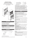
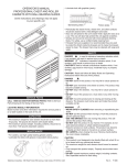
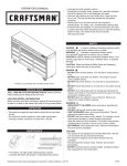
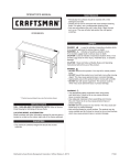
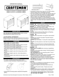
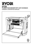
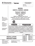
OPERATOR’S MANUAL
Ball bearing
5-DRAWER BB TOOL CENTER - model # 31013
Friction slides
• Periodically the drawer fronts, drawer trim, and other surfaces
should be cleaned with a mild detergent and water.
• Auto wax will preserve the unit’s luster finish. Apply the wax as
to a car. The wax will also help protect the unit against scratches.
• Grease and oil can be removed with most standard cleaning
fluids. For safety, use a nonflammable cleaning fluid.
• If drawer liners are supplied, it is recommended they are used
to protect the finish inside the drawers and to make the drawers
easier to clean. The drawer liners may be cleaned with soap and
water.
safety
DANGER
is used to indicate a hazardous situation which,
if not avoided, will result in serious injury or death.
WARNING
indicates a hazardous situation which, if not
avoided, could result in serious injury or death.
Caution is used to indicate a hazardous situation which, if not
avoided, may result in minor injury, moderate injury, or property
damage.
CAUTION: Read and follow all Safety Rules and Operating
Instructions before first use of this product.
SERVICE PARTS
Call 1-800-366-7278 for Service Parts. Refer to Service
Parts Drawing for full listing of Service Parts.
Locating Model # Information
Model numbers and other information required for service parts is
located on a label on top shelf behind the logo.
capacities
• The maximum weight for each drawer should be no more than
25 lbs.
• Empty weight of the unit is: 70 lbs
• The maximum product weight, including contents, should be no
more than 400 lbs.
maintenance
• For casters, use high quality bearing grease, (yearly).
• Lubricate the slides with grease or equivalent,(twice yearly.)
• Lubricate lock with graphite, (yearly).
DANGER
• DO NOT stand on this product. You may fall, which may cause
personal injury.
• DO NOT step in drawers. You may fall, which may cause personal
injury.
• USE THE BRAKES when not moving this product. This will prevent the product from rolling, which may cause personal injury or
product damage.
• APPROPRIATELY SECURE this product before moving with a
forklift.
• DO NOT tow with power equipment. The product could tip, which
may cause personal injury or prduct damage.
WARNING
• WEAR SAFETY GLASSES when removing or repositioning the
slides. The tool could slip, which may cause personal injury.
• DO NOT mount this product on a truck bed or any other moving
object. This may cause personal injury or product damage.
• DO NOT alter this product in any manner. For example, do not
weld external lockbars or attach electrical equipment. This may
cause personal injury or product damage.
• UNIT MUST BE located on a level surface. The product may become unstable and tip if stored or moved on an un-level surface,
which may cause personal injury or product damage.
• Lock the drawers before moving this product. The drawers could
come open and make the product unstable and tip, which may
cause personal injury or product damage.
• DO NOT pull this product when moving it. Push the product to
prevent personal injury.
CAUTION
• BE CAREFUL when opening more than one drawer. The product
may become unstable and tip, which may cause personal injury or
product damage.
Sears Brands Management Corporation, Hoffman Estates, IL 60179 USA
F1842
hardware
ASSEMBLY
TOOLS REQUIRED:
Flat-tip Screwdriver
3/8-in Wrench
Remove Chest From Roll-Away
• The unit comes with the chest secured to the inside of
the roll-away by either two or four 1/4-20 bolts.
• Lay the roll-away down on its back. Use packaging
material to protect the paint finish.
• Remove the securing bolts from the underside of the
roll-away. Save the screws for mounting the chest to the
roll-away.
• Remove the chest.
HARDWARE REQUIRED:
Grommet (Qty: 2)
CASTER INSTALLATION
Items Needed:
1/4-20 x .438-in HW Screw (Qty: 16)
1/4-20 Hex Nuts (Qty: 16)
1/4-20 Hex Nut (Qty: 16)
Process:
NOTE: Use adequate manpower for this operation.
• Remove the bottom drawer. See drawer removal
instructions.
• Lay the unit on its back, use packaging material to
protect the paint finish.
• Attach the casters to unit using (4) 1/4-20 x .438-in
Screws and (4) 1/4-20 Nuts per caster. Mount both swivel
casters on the same side of the unit. Wrench-tighten.
• Return the unit to its upright position.
• Reinstall bottom drawer.
1/4-20 x .438-in HW Screw (Qty: 16)
Carton Contents
Chest:
Literature
Cabinet:
Literature
Hardware bag
Caster pack
Nut
Caster pack
Bolt
mounting chest
• Remove the drawer from the roll-away (refer to the
drawer removal instructions).
• Lift the chest onto the roll-away. Line up the holes in
the bottom of the chest with the holes in the top of the
roll-away.
2
Lever Style - Lift or lower (depending on the slide) the
release lever on both sides, (this allows the slides to ride
over the stops). Pull out to remove.
• Attach the chest using two 1/4-20 screws that were used
to secure the chest to the bottom of the roll-away.
• Wrench tighten all screws.
• Replace the drawer (refer to the drawer installation instructions).
• To remove the chest, reverse the procedure.
riser assembly
NOTE: When assembled, the riser should be the same
size, left to right, as the chest. Use adequate manpower
for this operation. Hardware call-out included with riser.
• Assemble the sides and the back (flange side up) together using four 8-32 x 1/4 pan head screws and four
8-32 hex nuts. Finger tighten.
• Position the riser assembly on the roll-away. Secure
using four 10-16 x 1/2 sheet metal screws. Wrench
tighten.
• Position the chest on the riser. Secure using four 10-16
x 1/2 sheet metal screws. Wrench tighten.
• Wrench tighten the risers four 8-32 x 1/4 pan head
screws and 8-32 hex nuts.
Tab Style - Depress the release tabs on both sides (this
allows the slides to ride over the stops).
Pull out to remove.
Chest
Back
Side
Friction Style - Fully extend the drawer. Insert screwdriver
into the slot in the side and push in on the stop until it
clears the lance. Pull drawer just past lance before
releasing stop. Repeat the process for the other slide.
Cart
operation
REMOVING DRAWERS
• Empty the drawer.
• Fully extend the drawer
Release
3
Removing and Installing Slides from Unit
reinstall drawers
Ball bearing slide - Pull slides and slide carrier out to fully
extended position (see illustration). Hold the slide on the
cabinet while aligning it with the slide on drawer. Slightly
insert one side and repeat for the other side. Slowly push
drawer to its fully closed position to engage slide. Open
drawer and reclose to ensure proper operation.
• First remove the drawer. (See section A)
To remove the slide:
• Push slide to the closed position.
• Insert flat tip screw driver between slide and unit, behind
rear rectangular cutout.(See illustration.)
• Rotate screw driver ¼ turn to force slide away from unit.
• Push on front of slide pushing it towards back of the unit.
Slide Carrier
Slide
To attach the slide:
• Extend slide and locate lances within respective
cutout in carrier.
• Pull slide forward until slide locks back into place.
• Reinstall drawer following drawer installation procedure.(See section B)
TO LOCK CHEST
• Insert the lockbar (which stores in the top tray), tabbed end up, into the slot in the top tray and down into the slot in the base. Close the cover and lock with the key.
Friction slide - Fully extend slides in cabinet. Hold the
slide on the cabinet while aligning it with the slide on
drawer. Push the drawer into the unit until the drawer
fully engages slides. Open drawer and reclose to ensure
proper operation. (If stop does not engage slide, lightly
deflect the stop with screwdriver.)
TO LOCK ROLL-AWAY
•
•
•
Slide
Stop
The lockbar for the roll-away is stored in a slot in the top front corner of the unit.
Insert the straight end of the lockbar into the slot in
the base.
Move the lockbar toward the unit until the bent end fits into the slot near the lock. Lock with the key.
panel
• If your unit is equipped with a storage compartment with a panel at the bottom, pull panel out, lift up and push panel back into unit to gain access to compartment.
4
MANUAL DE USUARIO
Cojinetes de bolas
CENTRO PARA HERRAMIENTAS CON COJINETES DE
BOLAS (BB, EN INGLÉS) DE CINCO CAJONES
modelo no. 31013
Correderas de friccion
• Lubrique la cerradura con grafito (anualmente).
• Limpie con detergente suave y agua los frontales y los bordes laterales
de los cajones y las demás superficies.
• La cera para automóviles preservará el acabado brilloso de la unidad.
Aplique la cera como lo haría al carro. La cera también ayudará a proteger la unidad contra raspones.
• La grasa y el aceite pueden retirarse con la mayoría de los líquidos
estándar para limpieza. Por razones de seguridad, utilice un líquido
incombustible para limpieza.
• Si se suministran forros para las gavetas, se recomienda que se utilicen
para proteger el acabado interno de las mismas y para facilitar la limpieza. Los forros para gavetas pueden limpiarse con agua y jabón.
SEGURIDAD
PELIGRO
se utiliza para indicar una situación peligrosa que, de
no evitarse, resultará en lesiones graves o la muerte.
ADVERTENCIA
indica una situación peligrosa que, de no
evitarse, podría producir lesiones graves o la muerte.
PRECAUCIÓN se utiliza para indicar una situación peligrosa que, de
no evitarse, puede derivar en lesiones leves o moderadas, o en daño a la
propiedad.
ATENCIÓN: Lea y siga todas las Normas de Seguridad y las
Instrucciones de Funcionamiento antes de utilizar por primera vez este
producto.
PELIGRO
• NO se ponga de pie sobre esta unidad. Puede caerse u ocasionar que Piezas de servicio
En estados Unidos llame al 1-800-659-7084 para
piezas de repuesto. Fuera de Estados Unidos
llame a su distribuidor local. Suministre el número de
modelo al comunicarse.
UBICACIÓN DE INFORMACIÓN DEL No. DE MODELO
El número de modelo y demás información requerida para las piezas de
servicio se encuentran en una etiqueta en el lado interior derecho de la
gaveta superior.
CAPACIDAD
•El peso máximo en cada gaveta no debe ser mayor de 11,4 kg.
• El peso vacío de la unidad es 31,8 kg.
• El peso máximo del producto, incluyendo su contenido,
no debe ser mayor de 181,8 kg.
MANTENIMIENTO
• Para las ruedas, utilice grasa para rodamientos de alta calidad (anualmente).
el producto se vuelque.
• NO abra más de una gaveta. El producto podría quedar inestable y volcarse.
• NO utilice las gavetas como peldaños. Puede caerse u ocasionar que el producto se vuelque.
• No monte este producto en una cama de carro o ninguÌn otro objeto móvil.
• NO mueva la unidad antes de cerrar y asegurar todas las gavetas. Las gavetas podrían abrirse y hacer que la unidad se vuelva inestable y se vuelque.
ADVERTENCIA
• USE GAFAS DE SEGURIDAD al quitar o volver a poner las corred-
eras.
• NO hale la unidad, empújela cuando la mueva.
• UTILICE LOS FRENOS cuando el producto no esté en movimiento. Esto
impedirá que se deslice.
•N
O altere la unidad en modo alguno. Por ejemplo, no suelde las barras
de sujeción externas ni le incorpore equipos eléctricos.
• Mantenga la unidad en superficies niveladas. La unidad puede tornarse
inestable y volcarse si se almacena o se moviliza en una superficie no
nivelada.
• TENGA cuidado cuando cierre la tapa. Quite las manos antes de que la
tapa cierre completamente.
PRECAUCIÓN
• Este producto no está diseñado para ser levantado directamente con un
montacargas, ni para ser remolcado con unidades mecanizadas.
• Nunca debe exceder el peso máximo de cada gaveta.
• Sólo transporte esta unidad cuando esté vacía. Asegúrela adecuadamente
cuando la transporte.
• NO exceda el peso máximo del producto, incluyendo el contenido. Refiérase
a las Capacidades para más información.
• Lubrique las guías con grasa o equivalente (dos veces por año).
Distribuido cerca Sears Brands Management Corporation, Hoffman Estates, IL 60179
F1842
FERRETERÍA
ENSAMBLAJE
HERRAMIENTAS NECESARIAS:
QUITAR EL BAÚL DE LA PIEZA DESLIZANTE
Destornillador, punta de cruz
Llave Inglesa de 8mm
• La unidad tiene un baúl fijado por dentro a una pieza deslizante ya sea por dos o cuatro pernos 1/4-20.
• Acuesta la pieza deslizante boca arriba. Usa el material del
empaque para proteger el acabado de la pintura.
• Quita los pernos de fijación en el fondo de la pieza deslizante.
Guarda los tornillos para montar el baúl sobre la pieza anterior.
• Quita el baúl.
PIEZAS INCLUIDAS:
INSTALACION DEL TIRADOR (Solo Gabinete)
Remache a Presión (Cant: 2)
Elementos necesarios:
No. 1/4-20 X .438-in (Cant.: 16)
No. 1/4-20 X Tuerca (Cant.: 16)
Destornillador, punta de cruz
Llave Inglesa de 3/8-in (Llave de 10mm)
Tuerca Hexagonal de 1/4-20 (Cant: 16)
Proceso:
• Acueste el carro sobre su parte trasera. Proteja el acabado de la
unidad con el material de embalaje. (Ver Sección de Operación:
Sección B.)
• Instale las dos ruedecillas giratorias en el mismo lado de la
unidad que la manija lateral.
• Fije las ruedecillas usando (4) 1/4 - 20 x .438-in tornillos y (4)
1/4 x 20 tuercas en cada ruedecilla.
• Apriete todos los tornillos con una llave de tuercas. Se recomienda no apretar a más de 0,92 kg-m.
• Vuelva a colocar la unidad en posición vertical.
Tornillo 1/4-20 x .438-in HW (Cant:16)
CONTENIDO DE LA CAJA DE CARTÓN
Tuerca
Baúl:
Material impreso
Gabinete:
Material impreso
Bolsa de accesorios
Paquete de ruedas
Tornillo
Paquete de ruedas
Montar el baúl
• Quita el cajón de la pieza deslizante (ver las instrucciones
correspondientes).
• Alza el baúl y colócalo sobre la pieza deslizante. Alinea los
orificios en el fondo del baúl con los superiores de la pieza
deslizante.
2
Estilo palanca – Levante o baje (dependiendo de la corredera)
• Fija el baúl con los dos tornillos 1/4-20 usados para unir el baúl al
fondo de la pieza mencionada.
• Aprieta todos los tornillos con una llave.
• Vuelve a montar el cajón (ver las instrucciones correspondientes).
• Para quitar el baúl, invierte el proceso.
la palanca de liberación en ambos lados (esto permite que las
correderas pasen sobre los topes). Jale hacia afuera para retirar.
ensamblaje de la base
NOTA: Después de ensamblada, la base debe tener el mismo
tamaño del baúl, de lado a lado. Busca la ayuda necesaria para
esta operación. Lista de herrajes adjunta a la base.
• Ensambla los lados y el fondo (brida hacia arriba) con cuatro
tornillos de cabeza plana biselada 8-32 de 6,35 mm y cuatro
tuercas hexagonales 8-32. Aprieta con la mano.
• Coloca el ensamblado de la base sobre la pieza deslizante.
Fíjala con cuatro tornillos para hojalata 10-16 de 12,7 mm.
Aprieta con una llave.
• Monta el baúl sobre la base. Fíjalo con cuatro tornillos para
hojalata 10-16 de 12,7 mm. Aprieta con una llave.
• Aprieta los cuatro tornillos de cabeza plana biselada 8-32 de
2,5 mm y las tuercas hexagonales 8-32, de la base.
Estilo lengüeta – Oprima las lengüetas de liberación en ambos
lados (esto permite que las correderas pasen sobre los topes).
Jale hacia afuera para retirar.
Baúl
Parte
posterior
Lado
Estilo fricción - extienda completamente la gaveta. Inserte el
destornillador en la ranura del costado y presione el tope hasta
que libere el rejón. Hale la gaveta justo después del rejón antes
de liberar el tope. Repita el proceso con la otra corredera
Carro
FUNCIONAMIENTO
Nota: No todas las instrucciones de ensamblaje se refieren a tu modelo.
Remoción de gavetas
• Vacíe la gaveta.
• Abra completamente la gaveta.
Libere
3
Estilo fricción - extienda completamente la gaveta. Inserte el
destornillador en la ranura del costado y presione el tope hasta
que libere el rejón. Hale la gaveta justo después del rejón antes
de liberar el tope. Repita el proceso con la otra corredera
QUITAR E INSTALAR LAS CORREDERAS DE LA UNIDA
• Primero quita el cajón. (Ver la sección A)
Para quitar la corredera:
• Empuja la corredera hasta que quede en la posición de cerrado.
• Inserta la punta de un destornillador plano entre la corredera y la
unidad, detrás de la ranura rectangular trasera. (Ver imagen).
• Rota el destornillador ¼ de vuelta para separar la corredera de la
unidad.
• Empuja el frente de la corredera hacia la parte trasera de la unidad.
instalación de gavetas
Correderas de rodamientos esféricos - hale hacia afuera
las correderas y el soporte de las correderas hasta que queden
en posición totalmente extendida (ver ilustración). Sostenga la
corredera en el gabinete mientras lo alinea con la corredera de la
gaveta.
Instalar la corredera:
• Extiende la corredera y busca las lancetas en cada una de
las ranuras de los rieles.
• Empuja la corredera hacia adelante hasta que la corredera
quede fija en su lugar.
• Vuelve a colocar el cajón correctamente según las instrucciones. (Ver sección B)
Soporte de las correderas
CERRAR EL BAÚL
• Insertar la barra de cierre (ubicada en la bandeja superior),
con la pestaña final hacia arriba, dentro de las ranuras de la
bandeja superior y de la base. Cierra las tapas y usa la llave
para bloquear.
Corredera
BLOQUEAR LA PIEZA DESLIZANTE
• En la ranura de la esquina superior frontal de la unidad encontrarás la barra de cierre de la pieza deslizante.
• Inserta el extremo recto de la barra de cierre dentro de la ranura
de la base.
• Mueve la barra de cierre hacia la unidad hasta que el extremo
curvo encaje en la ranura cerca de la cerradura. Cierra con
llave.
panel
• Si la unidad tiene un compartimento de almacenamiento con
un panel en el fondo; hala hacia afuera, alza y empuja el panel
dentro de la unidad para tener acceso al compartimento.
4