1
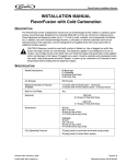
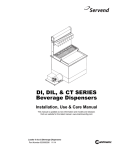
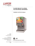
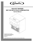
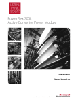
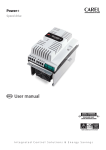
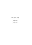
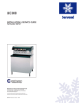
Installation Instructions for DF/ED250PRO Field Kit
INSTALLATION INSTRUCTIONS
DF/ED250PRO F IELD KIT (P/N 629087544)
Installation of Low CO2 Indicator Light
Parts List
Item No.
1
2
3
4
5
6
7
8
9
10
11
12
13
14
Part Number
620313223
77060500
40502
77010400
77045700
178025100
33666
620316401
620316402
620313651
32870
50705
620920638
620919569
Description
CO2 Pressure Switch
Tee 1/4MFL
O-Clamp
1/4 Barb Stem
1/4 Flare Swivel Nut
1/4 Flare Washer
Indicator Light 24V
CO2 Light Harness
CO2 Pressure Switch Harness
Jumper CO2 Pressure Switch
Splice
Cable Tie
Label Low CO2 Light
Installation Instructions
Qty.
1
1
2
2
2
3
1
1
1
1
2
8
1
1
CAUTION: Disconnect electrical power to the dispenser before proceeding with the
CO2 indicator light installation.
CAUTION: The Beverage System (water and CO2) must be depressurized and drained
before proceeding with the installation.
1. Remove the upper front panel which is secured to the cabinet by “hooks” that fit into slots
on the cabinet front flange. Lift up on the panel right and left sides to disengage the hooks
from the slots and then rotate the panel downward and forward to remove from the cabinet.
Disconnect the (3) electrical harnesses at the rear of the front panel.
2. Remove the lower front splash panel (2 screws).
3. Locate the CO2 supply line (1/4 beverage tubing) to the carbonator tank located on the
right side of the unit above the coldplate (see Fig. 1). Cut this line in an area that will be
accessible for future servicing and install the CO2 pressure switch with the fittings provided in
the kit (see Fig. 3).
4. Refer to Fig. 2 for installing the CO2 indicator light on the upper front panel. Remove the
lid and straw holder by loosening (3) screws at the “key-holes” and lifting up to clear the screw
heads. Remove the lower front ice portion control enclosure (4 screws) and disconnect the
electrical harnesses as needed for reworking the enclosure. Locate and drill a 1/2 in. diameter hole in the enclosure as shown in Fig. 2 for the indicator light. Insert the light from the
front and “snap” into the mounting hole.
5. Refer to the wiring detail of Fig. 4 to complete the electrical hook-up of the indicator light to
the pressure switch and the 24V beverage transformer power source.
6. Route the electrical wires to the CO2 pressure switch behind the beverage panel with the
harnesses from the unit’s electrical control box. Remove the (6) screws securing the beverRelease Date: October 9, 2002
© 2002, IMI Cornelius Inc.
Revision: A
-1-
Publication Number: 620919569
Installation Instructions for DF/ED250PRO Field Kit
age panel to the cabinet. The panel can now be pulled down to provide access for routing the
pressure switch wires. Secure the wiring with the plastic cable ties provided in the kit to avoid
“pinching” (cutting) the wire insulation when the panels are assembled to the cabinet.
7. Connect electrical power to the unit. Before opening the water and CO2 supply valves to
the beverage system, verify that the CO2 indicator light is on. The indicator light should go off
when the CO2 supply valve is opened.
8. Check for proper operation of the ice portion control system and the beverage system.
Refer to the operation instructional label located on the upper front panel and the owners
manual. The unit is now ready for operation.
Beverage Valve
& Auto/Manual
Harness From
E-Box
BEVERAGE VALVE
Manual Ice
Dispense PB
Switch Cord
Asy From E-Box
& AUTO/MANUAL
HARNESS FROM E-BOX
MANUAL ICE
DISPENSE PB
SWITCH CORD
ASY FROM E-BOX
Cut CO2 Supply
Line See CO2
Pressure Switch
Install Detail
CO2 Inlet Line
To Regulator
CUT CO2 SUPPLY
LINE. SEE CO2 PRESSURE SWITCH
CO2 INLET
INSTALL DETAIL
LINE TO REGULATOR
CO2 Supply Line
To Carbonator Tank
CO2 SUPPLY
LINE TO
CARBONATOR TANK
Figure 1.
Publication Number: 620919569
-2-
© 2002, IMI Cornelius Inc.
Installation Instructions for DF/ED250PRO Field Kit
See Wiring Detail
SEE WIRING DETAIL
9
9
88
77
6.000
6.000
DRILL .500.500
ø HOLE
Drill
Hole
1.750
1.750
13
13
Figure 2.
© 2002, IMI Cornelius Inc.
-3-
Publication Number: 620919569
Installation Instructions for DF/ED250PRO Field Kit
CO2 Supply Line
CO2 SUPPLY LINE
To Carbonator
TANK IN
Tank in Dispenser
TO CARBONATOR
DISPENSER
33
55
4
4
6
6
1
22
1
3
3
66
44
55
33
CO2 SUPPLY
LINE
CO2
Supply
Line
CO2 Pressure Switch Detail
CO2 PRESSURE SWITCH DETAIL
Figure 3.
Publication Number: 620919569
-4-
© 2002, IMI Cornelius Inc.
Installation Instructions for DF/ED250PRO Field Kit
B
W
B
L
L
K
K
W
H
T
T
H
Beverage
BEVERAGE
XFMR
XFMR
Yellow w/
Black Stripe
YELLOW W/
Yellow
YELLOW
BLACK STRIPE
Splice
SPLICE
11
11
Black
BLACK
10
Yellow
YELLOW
10
88
Red
RED
9
Low CO2
LOW CO2
Light 24V
9
LIGHT
24V
Harness
Disconnect
Housing
HARNESS
DISCONNECT
HOUSING
CO2 Pressure
Front
FRONT
Panel
PANEL
Switch
Low CO2 Indicator Light Wiring Detail
LOW CO2 INDICATOR LIGHT WIRING DETAIL
Figure 4.
© 2002, IMI Cornelius Inc.
-5-
Publication Number: 620919569