1
Catalyst 2960-XR Switch VLAN Configuration Guide, Cisco IOS Release
15.0(2)EX1
First Published: August 08, 2013
Americas Headquarters
Cisco Systems, Inc.
170 West Tasman Drive
San Jose, CA 95134-1706
USA
http://www.cisco.com
Tel: 408 526-4000
800 553-NETS (6387)
Fax: 408 527-0883
Text Part Number: OL-29440-01
THE SPECIFICATIONS AND INFORMATION REGARDING THE PRODUCTS IN THIS MANUAL ARE SUBJECT TO CHANGE WITHOUT NOTICE. ALL STATEMENTS,
INFORMATION, AND RECOMMENDATIONS IN THIS MANUAL ARE BELIEVED TO BE ACCURATE BUT ARE PRESENTED WITHOUT WARRANTY OF ANY KIND,
EXPRESS OR IMPLIED. USERS MUST TAKE FULL RESPONSIBILITY FOR THEIR APPLICATION OF ANY PRODUCTS.
THE SOFTWARE LICENSE AND LIMITED WARRANTY FOR THE ACCOMPANYING PRODUCT ARE SET FORTH IN THE INFORMATION PACKET THAT SHIPPED WITH
THE PRODUCT AND ARE INCORPORATED HEREIN BY THIS REFERENCE. IF YOU ARE UNABLE TO LOCATE THE SOFTWARE LICENSE OR LIMITED WARRANTY,
CONTACT YOUR CISCO REPRESENTATIVE FOR A COPY.
The Cisco implementation of TCP header compression is an adaptation of a program developed by the University of California, Berkeley (UCB) as part of UCB's public domain version
of the UNIX operating system. All rights reserved. Copyright © 1981, Regents of the University of California.
NOTWITHSTANDING ANY OTHER WARRANTY HEREIN, ALL DOCUMENT FILES AND SOFTWARE OF THESE SUPPLIERS ARE PROVIDED “AS IS" WITH ALL FAULTS.
CISCO AND THE ABOVE-NAMED SUPPLIERS DISCLAIM ALL WARRANTIES, EXPRESSED OR IMPLIED, INCLUDING, WITHOUT LIMITATION, THOSE OF
MERCHANTABILITY, FITNESS FOR A PARTICULAR PURPOSE AND NONINFRINGEMENT OR ARISING FROM A COURSE OF DEALING, USAGE, OR TRADE PRACTICE.
IN NO EVENT SHALL CISCO OR ITS SUPPLIERS BE LIABLE FOR ANY INDIRECT, SPECIAL, CONSEQUENTIAL, OR INCIDENTAL DAMAGES, INCLUDING, WITHOUT
LIMITATION, LOST PROFITS OR LOSS OR DAMAGE TO DATA ARISING OUT OF THE USE OR INABILITY TO USE THIS MANUAL, EVEN IF CISCO OR ITS SUPPLIERS
HAVE BEEN ADVISED OF THE POSSIBILITY OF SUCH DAMAGES.
Any Internet Protocol (IP) addresses and phone numbers used in this document are not intended to be actual addresses and phone numbers. Any examples, command display output, network
topology diagrams, and other figures included in the document are shown for illustrative purposes only. Any use of actual IP addresses or phone numbers in illustrative content is unintentional
and coincidental.
Cisco and the Cisco logo are trademarks or registered trademarks of Cisco and/or its affiliates in the U.S. and other countries. To view a list of Cisco trademarks, go to this URL: http://
www.cisco.com/go/trademarks. Third-party trademarks mentioned are the property of their respective owners. The use of the word partner does not imply a partnership
relationship between Cisco and any other company. (1110R)
© 2013
Cisco Systems, Inc. All rights reserved.
CONTENTS
Preface
Preface xi
Document Conventions xi
Related Documentation xiii
Obtaining Documentation and Submitting a Service Request xiii
CHAPTER 1
Using the Command-Line Interface 1
Information About Using the Command-Line Interface 1
Command Modes 1
Using the Help System 3
Understanding Abbreviated Commands 4
No and default Forms of Commands 4
CLI Error Messages 4
Configuration Logging 5
How to Use the CLI to Configure Features 5
Configuring the Command History 5
Changing the Command History Buffer Size 6
Recalling Commands 6
Disabling the Command History Feature 7
Enabling and Disabling Editing Features 7
Editing Commands through Keystrokes 8
Editing Command Lines That Wrap 9
Searching and Filtering Output of show and more Commands 10
Accessing the CLI through a Console Connection or through Telnet 11
CHAPTER 2
Configuring VTP 13
Finding Feature Information 13
Prerequisites for VTP 13
Catalyst 2960-XR Switch VLAN Configuration Guide, Cisco IOS Release 15.0(2)EX1
OL-29440-01
iii
Contents
Information About VTP 14
VTP 14
VTP Domain 14
VTP Modes 15
VTP Advertisements 16
VTP Version 2 17
VTP Version 3 17
VTP Pruning 18
VTP and Switch Stacks 20
VTP Configuration Guidelines 20
Configuration Requirements 20
VTP Settings 20
Domain Names for Configuring VTP 21
Passwords for the VTP Domain 21
VTP Version 22
Default VTP Configuration 23
How to Configure VTP 24
Configuring VTP Mode 24
Configuring a VTP Version 3 Password 26
Configuring a VTP Version 3 Primary Server 27
Enabling the VTP Version 28
Enabling VTP Pruning 29
Configuring VTP on a Per-Port Basis 31
Adding a VTP Client Switch to a VTP Domain 32
Monitoring VTP 34
Configuration Examples for VTP 35
Example: Configuring the Switch as a VTP Server 35
Example: Configuring a Hidden Password 35
Example: Configuring a VTP Version 3 Primary Server 35
Example: Configuring VTP on a Per-Port Basis 36
Where to Go Next 36
Additional References 36
Feature History and Information for VTP 37
CHAPTER 3
Configuring VLANs 39
Catalyst 2960-XR Switch VLAN Configuration Guide, Cisco IOS Release 15.0(2)EX1
iv
OL-29440-01
Contents
Finding Feature Information 39
Prerequisites for VLANs 39
Restrictions for VLANs 40
Information About VLANs 40
Logical Networks 40
Supported VLANs 41
VLAN Port Membership Modes 41
Normal-Range VLAN Overview 42
Token Ring VLANs 43
Normal-Range VLANs Configuration Process 43
VLAN Configuration Saving Process 43
Normal-Range VLAN Configuration Guidelines 44
Extended-Range VLAN Configuration Guidelines 45
Default Ethernet VLAN Configuration 46
Default VLAN Configuration 46
How to Configure VLANs 47
How to Configure Normal-Range VLANs 47
Creating or Modifying an Ethernet VLAN 47
Deleting a VLAN 49
Assigning Static-Access Ports to a VLAN 50
How to Configure Extended-Range VLANs 52
Creating an Extended-Range VLAN 52
Creating an Extended-Range VLAN with an Internal VLAN ID 54
Monitoring VLANs 56
Configuration Examples 57
Example: Creating a VLAN Name 57
Example: Configuring a Port as Access Port 57
Example: Creating an Extended-Range VLAN 57
Where to Go Next 58
Additional References 58
Feature History and Information for VLAN 59
CHAPTER 4
Configuring VLAN Trunks 61
Finding Feature Information 61
Prerequisites for VLAN Trunks 61
Catalyst 2960-XR Switch VLAN Configuration Guide, Cisco IOS Release 15.0(2)EX1
OL-29440-01
v
Contents
Restrictions for VLAN Trunks 62
Information About VLAN Trunks 62
Trunking Overview 62
Trunking Modes 62
Layer 2 Interface Modes 63
Allowed VLANs on a Trunk 64
Load Sharing on Trunk Ports 64
Network Load Sharing Using STP Priorities 64
Network Load Sharing Using STP Path Cost 65
Feature Interactions 66
Default Layer 2 Ethernet Interface VLAN Configuration 66
How to Configure VLAN Trunks 67
Configuring an Ethernet Interface as a Trunk Port 67
Configuring a Trunk Port 67
Defining the Allowed VLANs on a Trunk 69
Changing the Pruning-Eligible List 71
Configuring the Native VLAN for Untagged Traffic 72
Configuring Trunk Ports for Load Sharing 73
Configuring Load Sharing Using STP Port Priorities 73
Configuring Load Sharing Using STP Path Cost 77
Configuration Examples for VLAN Trunking 80
Example: Configuring an IEEE 802.1Q Trunk 80
Example: Removing a VLAN 81
Where to Go Next 81
Additional References 81
Feature History and Information for VLAN Trunks 82
CHAPTER 5
Configuring Private VLANs 83
Finding Feature Information 83
Prerequisites for Private VLANs 83
Secondary and Primary VLAN Configuration 84
Private VLAN Port Configuration 85
Restrictions for Private VLANs 86
Limitations with Other Features 86
Information About Private VLANs 87
Catalyst 2960-XR Switch VLAN Configuration Guide, Cisco IOS Release 15.0(2)EX1
vi
OL-29440-01
Contents
Private VLAN Domains 87
Secondary VLANs 88
Private VLANs Ports 88
Private VLANs in Networks 89
IP Addressing Scheme with Private VLANs 90
Private VLANs Across Multiple Switches 90
Private VLAN Interaction with Other Features 91
Private VLANs and Unicast, Broadcast, and Multicast Traffic 91
Private VLANs and SVIs 92
Private VLANs and Switch Stacks 92
Private VLAN Configuration Tasks 92
Default Private VLAN Configuration 93
How to Configure Private VLANs 93
Configuring and Associating VLANs in a Private VLAN 93
Configuring a Layer 2 Interface as a Private VLAN Host Port 96
Configuring a Layer 2 Interface as a Private VLAN Promiscuous Port 98
Mapping Secondary VLANs to a Primary VLAN Layer 3 VLAN Interface 99
Monitoring Private VLANs 101
Configuration Examples for Private VLANs 102
Example: Configuring a Primary VLAN, Isolated VLAN, and a Community of VLANs 102
Example: Configuring an Interface as a Host Port 102
Example: Configuring an Interface as a Private VLAN Promiscuous Port 103
Example: Mapping Secondary VLANs to a Primary VLAN Interface 103
Example: Monitoring Private VLANs 104
Where to Go Next 104
Additional References 104
Feature History and Information for Private VLANs 105
CHAPTER 6
Configuring VMPS 107
Finding Feature Information 107
Prerequisites for VMPS 107
Restrictions for VMPS 108
Information About VMPS 108
Dynamic VLAN Assignments 108
Dynamic-Access Port VLAN Membership 109
Catalyst 2960-XR Switch VLAN Configuration Guide, Cisco IOS Release 15.0(2)EX1
OL-29440-01
vii
Contents
Default VMPS Client Configuration 110
How to Configure VMPS 110
Entering the IP Address of the VMPS 110
Configuring Dynamic-Access Ports on VMPS Clients 111
Reconfirming VLAN Memberships 113
Changing the Reconfirmation Interval 114
Changing the Retry Count 115
Troubleshooting Dynamic-Access Port VLAN Membership 116
Monitoring the VMPS 117
Configuration Example for VMPS 117
Example: VMPS Configuration 117
Where to Go Next 118
Additional References 119
Feature History and Information for VMPS 120
CHAPTER 7
Configuring IEEE 802.1Q and Layer 2 Protocol Tunneling 121
Finding Feature Information 121
Prerequisites for Configuring Tunneling 121
IEEE 802.1Q Tunneling and Incompatibilities 122
Layer 2 Protocol Tunneling 122
Layer 2 Tunneling for EtherChannels 124
Information about Tunneling 124
IEEE 802.1Q and Layer 2 Protocol Overview 124
IEEE 802.1Q Tunneling 124
IEEE 802.1Q Tunneling Configuration Guidelines 127
Native VLANs 127
System MTU 128
Default IEEE 802.1Q Tunneling Configuration 129
Layer 2 Protocol Tunneling Overview 129
Layer 2 Protocol Tunneling on Ports 131
Default Layer 2 Protocol Tunneling Configuration 132
How to Configure Tunneling 133
Configuring an IEEE 802.1Q Tunneling Port 133
Configuring Layer 2 Protocol Tunneling 135
Configuring the SP Edge Switch 138
Catalyst 2960-XR Switch VLAN Configuration Guide, Cisco IOS Release 15.0(2)EX1
viii
OL-29440-01
Contents
Configuring the Customer Switch 141
Configuration Examples for IEEE 802.1Q and Layer 2 Protocol Tunneling 143
Example: Configuring an IEEE 802.1Q Tunneling Port 143
Example: Configuring Layer 2 Protocol Tunneling 144
Examples: Configuring the SP Edge and Customer Switches 145
Monitoring Tunneling Status 146
Where to Go Next 147
Additional References 147
Feature History and Information for Tunneling 148
CHAPTER 8
Configuring Voice VLANs 149
Finding Feature Information 149
Prerequisites for Voice VLANs 149
Restrictions for Voice VLANs 150
Information About Voice VLAN 150
Voice VLANs 150
Cisco IP Phone Voice Traffic 151
Cisco IP Phone Data Traffic 151
Voice VLAN Configuration Guidelines 152
Default Voice VLAN Configuration 153
How to Configure Voice VLAN 153
Configuring Cisco IP Phone Voice Traffic 153
Configuring the Priority of Incoming Data Frames 155
Monitoring Voice VLAN 157
Configuration Examples for Voice VLANs 157
Example: Configuring Cisco IP Phone Voice Traffic 157
Example: Configuring a Port Connected to an IP Phone Not to Change Frame Priority 158
Where to Go Next 158
Additional References 159
Feature History and Information for Voice VLAN 160
Catalyst 2960-XR Switch VLAN Configuration Guide, Cisco IOS Release 15.0(2)EX1
OL-29440-01
ix
Contents
Catalyst 2960-XR Switch VLAN Configuration Guide, Cisco IOS Release 15.0(2)EX1
x
OL-29440-01
Preface
This guide describes configuration information and examples for VLANs on the switch.
• Document Conventions, page xi
• Related Documentation, page xiii
• Obtaining Documentation and Submitting a Service Request, page xiii
Document Conventions
This document uses the following conventions:
Convention
Description
^ or Ctrl
Both the ^ symbol and Ctrl represent the Control (Ctrl) key on a keyboard.
For example, the key combination ^D or Ctrl-D means that you hold
down the Control key while you press the D key. (Keys are indicated in
capital letters but are not case sensitive.)
bold font
Commands and keywords and user-entered text appear in bold font.
Italic font
Document titles, new or emphasized terms, and arguments for which you
supply values are in italic font.
Courier font
Terminal sessions and information the system displays appear in courier
font.
Bold Courier font
Bold Courier font indicates text that the user must enter.
[x]
Elements in square brackets are optional.
...
An ellipsis (three consecutive nonbolded periods without spaces) after
a syntax element indicates that the element can be repeated.
|
A vertical line, called a pipe, indicates a choice within a set of keywords
or arguments.
Catalyst 2960-XR Switch VLAN Configuration Guide, Cisco IOS Release 15.0(2)EX1
OL-29440-01
xi
Preface
Document Conventions
Convention
Description
[x | y]
Optional alternative keywords are grouped in brackets and separated by
vertical bars.
{x | y}
Required alternative keywords are grouped in braces and separated by
vertical bars.
[x {y | z}]
Nested set of square brackets or braces indicate optional or required
choices within optional or required elements. Braces and a vertical bar
within square brackets indicate a required choice within an optional
element.
string
A nonquoted set of characters. Do not use quotation marks around the
string or the string will include the quotation marks.
<>
Nonprinting characters such as passwords are in angle brackets.
[]
Default responses to system prompts are in square brackets.
!, #
An exclamation point (!) or a pound sign (#) at the beginning of a line
of code indicates a comment line.
Reader Alert Conventions
This document uses the following conventions for reader alerts:
Note
Tip
Caution
Timesaver
Warning
Means reader take note. Notes contain helpful suggestions or references to material not covered in the
manual.
Means the following information will help you solve a problem.
Means reader be careful. In this situation, you might do something that could result in equipment damage
or loss of data.
Means the described action saves time. You can save time by performing the action described in the
paragraph.
Means reader be warned. In this situation, you might perform an action that could result in bodily
injury.
Catalyst 2960-XR Switch VLAN Configuration Guide, Cisco IOS Release 15.0(2)EX1
xii
OL-29440-01
Preface
Related Documentation
Related Documentation
Note
Before installing or upgrading the switch, refer to the switch release notes.
• Catalyst 2960-XR Switch documentation, located at:
http://www.cisco.com/go/cat2960xr_docs
• Cisco SFP and SFP+ modules documentation, including compatibility matrixes, located at:
http://www.cisco.com/en/US/products/hw/modules/ps5455/tsd_products_support_series_home.html
• Cisco Validated Designs documents, located at:
http://www.cisco.com/go/designzone
Obtaining Documentation and Submitting a Service Request
For information on obtaining documentation, submitting a service request, and gathering additional information,
see the monthly What's New in Cisco Product Documentation, which also lists all new and revised Cisco
technical documentation, at:
http://www.cisco.com/en/US/docs/general/whatsnew/whatsnew.html
Subscribe to the What's New in Cisco Product Documentation as a Really Simple Syndication (RSS) feed
and set content to be delivered directly to your desktop using a reader application. The RSS feeds are a free
service and Cisco currently supports RSS version 2.0.
Catalyst 2960-XR Switch VLAN Configuration Guide, Cisco IOS Release 15.0(2)EX1
OL-29440-01
xiii
Preface
Obtaining Documentation and Submitting a Service Request
Catalyst 2960-XR Switch VLAN Configuration Guide, Cisco IOS Release 15.0(2)EX1
xiv
OL-29440-01
CHAPTER
1
Using the Command-Line Interface
This chapter contains the following topics:
• Information About Using the Command-Line Interface, page 1
• How to Use the CLI to Configure Features, page 5
Information About Using the Command-Line Interface
This section describes the Cisco IOS command-line interface (CLI) and how to use it to configure your switch.
Command Modes
The Cisco IOS user interface is divided into many different modes. The commands available to you depend
on which mode you are currently in. Enter a question mark (?) at the system prompt to obtain a list of commands
available for each command mode.
You can start a CLI session through a console connection, through Telnet, a SSH, or by using the browser.
When you start a session, you begin in user mode, often called user EXEC mode. Only a limited subset of
the commands are available in user EXEC mode. For example, most of the user EXEC commands are one-time
commands, such as show commands, which show the current configuration status, and clear commands,
which clear counters or interfaces. The user EXEC commands are not saved when the switch reboots.
To have access to all commands, you must enter privileged EXEC mode. Normally, you must enter a password
to enter privileged EXEC mode. From this mode, you can enter any privileged EXEC command or enter
global configuration mode.
Using the configuration modes (global, interface, and line), you can make changes to the running configuration.
If you save the configuration, these commands are stored and used when the switch reboots. To access the
various configuration modes, you must start at global configuration mode. From global configuration mode,
you can enter interface configuration mode and line configuration mode.
This table describes the main command modes, how to access each one, the prompt you see in that mode, and
how to exit the mode.
Catalyst 2960-XR Switch VLAN Configuration Guide, Cisco IOS Release 15.0(2)EX1
OL-29440-01
1
Using the Command-Line Interface
Command Modes
Table 1: Command Mode Summary
Mode
Access Method
User EXEC
Begin a session
using Telnet, SSH,
or console.
Prompt
Exit Method
About This Mode
Switch>
Enter logout or
quit.
Use this mode to
• Change
terminal
settings.
• Perform basic
tests.
• Display
system
information.
Privileged EXEC
While in user EXEC
mode, enter the
enable command.
Global
configuration
While in privileged
EXEC mode, enter
the configure
command.
VLAN
configuration
While in global
configuration mode,
enter the vlan
vlan-id command.
Interface
configuration
While in global
configuration mode,
enter the interface
command (with a
specific interface).
Switch#
Switch(config)#
Switch(config-vlan)#
Switch(config-if)#
Enter disable to
exit.
Use this mode to
verify commands
that you have
entered. Use a
password to protect
access to this mode.
To exit to privileged
EXEC mode, enter
exit or end, or press
Ctrl-Z.
Use this mode to
configure
parameters that
apply to the entire
switch.
To exit to global
configuration mode,
enter the exit
command.
Use this mode to
configure VLAN
parameters. When
VTP mode is
transparent, you can
To return to
create
privileged EXEC
extended-range
mode, press Ctrl-Z
VLANs (VLAN IDs
or enter end.
greater than 1005)
and save
configurations in the
switch startup
configuration file.
To exit to global
Use this mode to
configuration mode, configure
enter exit.
parameters for the
Ethernet ports.
To return to
privileged EXEC
mode, press Ctrl-Z
or enter end.
Catalyst 2960-XR Switch VLAN Configuration Guide, Cisco IOS Release 15.0(2)EX1
2
OL-29440-01
Using the Command-Line Interface
Using the Help System
Mode
Access Method
Line configuration
While in global
configuration mode,
specify a line with
the line vty or line
console command.
Prompt
Exit Method
Switch(config-line)#
About This Mode
To exit to global
Use this mode to
configuration mode, configure
enter exit.
parameters for the
terminal line.
To return to
privileged EXEC
mode, press Ctrl-Z
or enter end.
Using the Help System
You can enter a question mark (?) at the system prompt to display a list of commands available for each
command mode. You can also obtain a list of associated keywords and arguments for any command.
SUMMARY STEPS
1. help
2. abbreviated-command-entry ?
3. abbreviated-command-entry <Tab>
4. ?
5. command ?
6. command keyword ?
DETAILED STEPS
Step 1
Command or Action
Purpose
help
Obtains a brief description of the help system in any
command mode.
Example:
Switch# help
Step 2
abbreviated-command-entry ?
Obtains a list of commands that begin with a particular
character string.
Example:
Switch# di?
dir disable disconnect
Step 3
abbreviated-command-entry <Tab>
Completes a partial command name.
Example:
Switch# sh conf<tab>
Switch# show configuration
Catalyst 2960-XR Switch VLAN Configuration Guide, Cisco IOS Release 15.0(2)EX1
OL-29440-01
3
Using the Command-Line Interface
Understanding Abbreviated Commands
Step 4
Command or Action
Purpose
?
Lists all commands available for a particular command
mode.
Example:
Switch> ?
Step 5
command ?
Lists the associated keywords for a command.
Example:
Switch> show ?
Step 6
command keyword ?
Lists the associated arguments for a keyword.
Example:
Switch(config)# cdp holdtime ?
<10-255> Length of time (in sec) that receiver
must keep this packet
Understanding Abbreviated Commands
You need to enter only enough characters for the switch to recognize the command as unique.
This example shows how to enter the show configuration privileged EXEC command in an abbreviated form:
Switch# show conf
No and default Forms of Commands
Almost every configuration command also has a no form. In general, use the no form to disable a feature or
function or reverse the action of a command. For example, the no shutdown interface configuration command
reverses the shutdown of an interface. Use the command without the keyword no to reenable a disabled feature
or to enable a feature that is disabled by default.
Configuration commands can also have a default form. The default form of a command returns the command
setting to its default. Most commands are disabled by default, so the default form is the same as the no form.
However, some commands are enabled by default and have variables set to certain default values. In these
cases, the default command enables the command and sets variables to their default values.
CLI Error Messages
This table lists some error messages that you might encounter while using the CLI to configure your switch.
Catalyst 2960-XR Switch VLAN Configuration Guide, Cisco IOS Release 15.0(2)EX1
4
OL-29440-01
Using the Command-Line Interface
Configuration Logging
Table 2: Common CLI Error Messages
Error Message
Meaning
How to Get Help
% Ambiguous command: "show
con"
You did not enter enough
characters for your switch to
recognize the command.
Reenter the command followed by
a question mark (?) with a space
between the command and the
question mark.
The possible keywords that you can
enter with the command appear.
% Incomplete command.
You did not enter all the keywords Reenter the command followed by
or values required by this
a question mark (?) with a space
command.
between the command and the
question mark.
The possible keywords that you can
enter with the command appear.
% Invalid input detected at
‘^’ marker.
You entered the command
Enter a question mark (?) to display
incorrectly. The caret (^) marks the all the commands that are available
point of the error.
in this command mode.
The possible keywords that you can
enter with the command appear.
Configuration Logging
You can log and view changes to the switch configuration. You can use the Configuration Change Logging
and Notification feature to track changes on a per-session and per-user basis. The logger tracks each
configuration command that is applied, the user who entered the command, the time that the command was
entered, and the parser return code for the command. This feature includes a mechanism for asynchronous
notification to registered applications whenever the configuration changes. You can choose to have the
notifications sent to the syslog.
Note
Only CLI or HTTP changes are logged.
How to Use the CLI to Configure Features
Configuring the Command History
The software provides a history or record of commands that you have entered. The command history feature
is particularly useful for recalling long or complex commands or entries, including access lists. You can
customize this feature to suit your needs.
Catalyst 2960-XR Switch VLAN Configuration Guide, Cisco IOS Release 15.0(2)EX1
OL-29440-01
5
Using the Command-Line Interface
Configuring the Command History
Changing the Command History Buffer Size
By default, the switch records ten command lines in its history buffer. You can alter this number for a current
terminal session or for all sessions on a particular line. This procedure is optional.
SUMMARY STEPS
1. terminal history [size number-of-lines]
DETAILED STEPS
Step 1
Command or Action
Purpose
terminal history [size number-of-lines]
Changes the number of command lines that the switch records during
the current terminal session in the privileged EXEC mode. You can
configure the size from 0 through 256.
Example:
Switch# terminal history size 200
Recalling Commands
To recall commands from the history buffer, perform one of the actions listed in this table. These actions are
optional.
Note
The arrow keys function only on ANSI-compatible terminals such as VT100s.
SUMMARY STEPS
1. Ctrl-P or use the up arrow key
2. Ctrl-N or use the down arrow key
3. show history
DETAILED STEPS
Command or Action
Purpose
Step 1
Ctrl-P or use the up arrow key
Recalls commands in the history buffer, beginning with the most recent command.
Repeat the key sequence to recall successively older commands.
Step 2
Ctrl-N or use the down arrow key Returns to more recent commands in the history buffer after recalling commands
with Ctrl-P or the up arrow key. Repeat the key sequence to recall successively
more recent commands.
Catalyst 2960-XR Switch VLAN Configuration Guide, Cisco IOS Release 15.0(2)EX1
6
OL-29440-01
Using the Command-Line Interface
Enabling and Disabling Editing Features
Step 3
Command or Action
Purpose
show history
Lists the last several commands that you just entered in privileged EXEC mode.
The number of commands that appear is controlled by the setting of the terminal
history global configuration command and the history line configuration
command.
Example:
Switch# show history
Disabling the Command History Feature
The command history feature is automatically enabled. You can disable it for the current terminal session or
for the command line. This procedure is optional.
SUMMARY STEPS
1. terminal no history
DETAILED STEPS
Step 1
Command or Action
Purpose
terminal no history
Disables the feature during the current terminal session in the
privileged EXEC mode.
Example:
Switch# terminal no history
Enabling and Disabling Editing Features
Although enhanced editing mode is automatically enabled, you can disable it, and reenable it.
SUMMARY STEPS
1. terminal editing
2. terminal no editing
DETAILED STEPS
Step 1
Command or Action
Purpose
terminal editing
Reenables the enhanced editing mode for the current terminal
session in the privileged EXEC mode.
Example:
Switch# terminal editing
Catalyst 2960-XR Switch VLAN Configuration Guide, Cisco IOS Release 15.0(2)EX1
OL-29440-01
7
Using the Command-Line Interface
Enabling and Disabling Editing Features
Step 2
Command or Action
Purpose
terminal no editing
Disables the enhanced editing mode for the current terminal session
in the privileged EXEC mode.
Example:
Switch# terminal no editing
Editing Commands through Keystrokes
The keystrokes help you to edit the command lines. These keystrokes are optional.
Note
The arrow keys function only on ANSI-compatible terminals such as VT100s.
Table 3: Editing Commands
Editing Commands
Description
Ctrl-B or use the left arrow key
Moves the cursor back one character.
Ctrl-F or use the right arrow key
Moves the cursor forward one character.
Ctrl-A
Moves the cursor to the beginning of the command
line.
Ctrl-E
Moves the cursor to the end of the command line.
Esc B
Moves the cursor back one word.
Esc F
Moves the cursor forward one word.
Ctrl-T
Transposes the character to the left of the cursor with
the character located at the cursor.
Delete or Backspace key
Erases the character to the left of the cursor.
Ctrl-D
Deletes the character at the cursor.
Ctrl-K
Deletes all characters from the cursor to the end of
the command line.
Ctrl-U or Ctrl-X
Deletes all characters from the cursor to the beginning
of the command line.
Ctrl-W
Deletes the word to the left of the cursor.
Catalyst 2960-XR Switch VLAN Configuration Guide, Cisco IOS Release 15.0(2)EX1
8
OL-29440-01
Using the Command-Line Interface
Enabling and Disabling Editing Features
Esc D
Deletes from the cursor to the end of the word.
Esc C
Capitalizes at the cursor.
Esc L
Changes the word at the cursor to lowercase.
Esc U
Capitalizes letters from the cursor to the end of the
word.
Ctrl-V or Esc Q
Designates a particular keystroke as an executable
command, perhaps as a shortcut.
Return key
Scrolls down a line or screen on displays that are
longer than the terminal screen can display.
Note
The More prompt is used for any output that
has more lines than can be displayed on the
terminal screen, including show command
output. You can use the Return and Space
bar keystrokes whenever you see the More
prompt.
Space bar
Scrolls down one screen.
Ctrl-L or Ctrl-R
Redisplays the current command line if the switch
suddenly sends a message to your screen.
Editing Command Lines That Wrap
You can use a wraparound feature for commands that extend beyond a single line on the screen. When the
cursor reaches the right margin, the command line shifts ten spaces to the left. You cannot see the first ten
characters of the line, but you can scroll back and check the syntax at the beginning of the command. The
keystroke actions are optional.
To scroll back to the beginning of the command entry, press Ctrl-B or the left arrow key repeatedly. You can
also press Ctrl-A to immediately move to the beginning of the line.
Note
The arrow keys function only on ANSI-compatible terminals such as VT100s.
The following example shows how to wrap a command line that extend beyond a single line on the screen.
SUMMARY STEPS
1. access-list
2. Ctrl-A
3. Return key
Catalyst 2960-XR Switch VLAN Configuration Guide, Cisco IOS Release 15.0(2)EX1
OL-29440-01
9
Using the Command-Line Interface
Searching and Filtering Output of show and more Commands
DETAILED STEPS
Step 1
Command or Action
Purpose
access-list
Displays the global configuration command entry that extends beyond
one line.
Example:
When the cursor first reaches the end of the line, the line is shifted ten
spaces to the left and redisplayed. The dollar sign ($) shows that the
line has been scrolled to the left. Each time the cursor reaches the end
of the line, the line is again shifted ten spaces to the left.
Switch(config)# access-list 101 permit tcp
10.15.22.25 255.255.255.0 10.15.22.35
Switch(config)# $ 101 permit tcp
10.15.22.25 255.255.255.0 10.15.22.35
255.25
Switch(config)# $t tcp 10.15.22.25
255.255.255.0 131.108.1.20 255.255.255.0
eq
Switch(config)# $15.22.25 255.255.255.0
10.15.22.35 255.255.255.0 eq 45
Step 2
Ctrl-A
Checks the complete syntax.
Example:
The dollar sign ($) appears at the end of the line to show that the line
has been scrolled to the right.
Switch(config)# access-list 101 permit tcp
10.15.22.25 255.255.255.0 10.15.2$
Step 3
Return key
Execute the commands.
The software assumes that you have a terminal screen that is 80 columns
wide. If you have a different width, use the terminal width privileged
EXEC command to set the width of your terminal.
Use line wrapping with the command history feature to recall and
modify previous complex command entries.
Searching and Filtering Output of show and more Commands
You can search and filter the output for show and more commands. This is useful when you need to sort
through large amounts of output or if you want to exclude output that you do not need to see. Using these
commands is optional.
SUMMARY STEPS
1. {show | more} command | {begin | include | exclude} regular-expression
DETAILED STEPS
Step 1
Command or Action
Purpose
{show | more} command | {begin | include | exclude}
regular-expression
Searches and filters the output.
Catalyst 2960-XR Switch VLAN Configuration Guide, Cisco IOS Release 15.0(2)EX1
10
OL-29440-01
Using the Command-Line Interface
Accessing the CLI through a Console Connection or through Telnet
Command or Action
Purpose
Example:
Expressions are case sensitive. For example, if you enter
| exclude output, the lines that contain output are not
displayed, but the lines that contain output appear.
Switch# show interfaces | include protocol
Vlan1 is up, line protocol is up
Vlan10 is up, line protocol is down
GigabitEthernet1/0/1 is up, line protocol is down
GigabitEthernet1/0/2 is up, line protocol is up
Accessing the CLI through a Console Connection or through Telnet
Before you can access the CLI, you must connect a terminal or a PC to the switch console or connect a PC to
the Ethernet management port and then power on the switch, as described in the hardware installation guide
that shipped with your switch.
If your switch is already configured, you can access the CLI through a local console connection or through a
remote Telnet session, but your switch must first be configured for this type of access.
You can use one of these methods to establish a connection with the switch:
• Connect the switch console port to a management station or dial-up modem, or connect the Ethernet
management port to a PC. For information about connecting to the console or Ethernet management
port, see the switch hardware installation guide.
• Use any Telnet TCP/IP or encrypted Secure Shell (SSH) package from a remote management station.
The switch must have network connectivity with the Telnet or SSH client, and the switch must have an
enable secret password configured.
• The switch supports up to 16 simultaneous Telnet sessions. Changes made by one Telnet user are
reflected in all other Telnet sessions.
• The switch supports up to five simultaneous secure SSH sessions.
After you connect through the console port, through the Ethernet management port, through a Telnet
session or through an SSH session, the user EXEC prompt appears on the management station.
Catalyst 2960-XR Switch VLAN Configuration Guide, Cisco IOS Release 15.0(2)EX1
OL-29440-01
11
Using the Command-Line Interface
Accessing the CLI through a Console Connection or through Telnet
Catalyst 2960-XR Switch VLAN Configuration Guide, Cisco IOS Release 15.0(2)EX1
12
OL-29440-01
CHAPTER
2
Configuring VTP
• Finding Feature Information, page 13
• Prerequisites for VTP, page 13
• Information About VTP, page 14
• Default VTP Configuration, page 23
• How to Configure VTP, page 24
• Monitoring VTP, page 34
• Configuration Examples for VTP, page 35
• Where to Go Next, page 36
• Additional References, page 36
• Feature History and Information for VTP, page 37
Finding Feature Information
Your software release may not support all the features documented in this module. For the latest feature
information and caveats, see the release notes for your platform and software release.
Use Cisco Feature Navigator to find information about platform support and Cisco software image support.
To access Cisco Feature Navigator, go to http://www.cisco.com/go/cfn. An account on Cisco.com is not
required.
Prerequisites for VTP
The following are prerequisites for VTP:
• Before you create VLANs, you must decide whether to use the VLAN Trunking Protocol (VTP) in your
network. Using VTP, you can make configuration changes centrally on one or more switches and have
those changes automatically communicated to all the other switches in the network. Without VTP, you
cannot send information about VLANs to other switches. VTP is designed to work in an environment
where updates are made on a single switch and are sent through VTP to other switches in the domain.
Catalyst 2960-XR Switch VLAN Configuration Guide, Cisco IOS Release 15.0(2)EX1
OL-29440-01
13
Configuring VTP
Information About VTP
It does not work well in a situation where multiple updates to the VLAN database occur simultaneously
on switches in the same domain, which would result in an inconsistency in the VLAN database.
• The switch supports 1005 VLANs when running the IP Lite image.
• However, the number of routed ports, SVIs, and other configured features affects the usage of the switch
hardware. If the switch is notified by VTP of a new VLAN and the switch is already using the maximum
available hardware resources, it sends a message that there are not enough hardware resources available
and shuts down the VLAN. The output of the show vlan user EXEC command shows the VLAN in a
suspended state.
Information About VTP
VTP
VTP is a Layer 2 messaging protocol that maintains VLAN configuration consistency by managing the
addition, deletion, and renaming of VLANs on a network-wide basis. VTP minimizes misconfigurations and
configuration inconsistencies that can cause several problems, such as duplicate VLAN names, incorrect
VLAN-type specifications, and security violations.
VTP functionality is supported across the stack, and all switches in the stack maintain the same VLAN and
VTP configuration inherited from the active switch. When a switch learns of a new VLAN through VTP
messages or when a new VLAN is configured by the user, the new VLAN information is communicated to
all switches in the stack.
When a switch joins the stack or when stacks merge, the new switches get VTP information from the active
switch.
VTP version 1 and version 2 support only normal-range VLANs (VLAN IDs 1 to 1005). VTP version 3
supports the entire VLAN range (VLANs 1 to 4094). Extended range VLANs (VLANs 1006 to 4094) are
supported only in VTP version 3. You cannot convert from VTP version 3 to VTP version 2 if extended
VLANs are configured in the domain.
VTP Domain
A VTP domain (also called a VLAN management domain) consists of one switch or several interconnected
switches or switch stacks under the same administrative responsibility sharing the same VTP domain name.
A switch can be in only one VTP domain. You make global VLAN configuration changes for the domain.
By default, the switch is in the VTP no-management-domain state until it receives an advertisement for a
domain over a trunk link (a link that carries the traffic of multiple VLANs) or until you configure a domain
name. Until the management domain name is specified or learned, you cannot create or modify VLANs on a
VTP server, and VLAN information is not propagated over the network.
If the switch receives a VTP advertisement over a trunk link, it inherits the management domain name and
the VTP configuration revision number. The switch then ignores advertisements with a different domain name
or an earlier configuration revision number.
Catalyst 2960-XR Switch VLAN Configuration Guide, Cisco IOS Release 15.0(2)EX1
14
OL-29440-01
Configuring VTP
VTP Modes
Note
Before adding a VTP client switch to a VTP domain, always verify that its VTP configuration revision
number is lower than the configuration revision number of the other switches in the VTP domain. Switches
in a VTP domain always use the VLAN configuration of the switch with the highest VTP configuration
revision number. If you add a switch that has a revision number higher than the revision number in the
VTP domain, it can erase all VLAN information from the VTP server and VTP domain.
When you make a change to the VLAN configuration on a VTP server, the change is propagated to all switches
in the VTP domain. VTP advertisements are sent over all IEEE trunk connections, including IEEE 802.1Q.
VTP dynamically maps VLANs with unique names and internal index associates across multiple LAN types.
Mapping eliminates excessive device administration required from network administrators.
If you configure a switch for VTP transparent mode, you can create and modify VLANs, but the changes are
not sent to other switches in the domain, and they affect only the individual switch. However, configuration
changes made when the switch is in this mode are saved in the switch running configuration and can be saved
to the switch startup configuration file.
Related Topics
Adding a VTP Client Switch to a VTP Domain, on page 32
VTP Modes
Table 4: VTP Modes
VTP Mode
Description
VTP server
In VTP server mode, you can create, modify, and delete VLANs, and specify other
configuration parameters (such as the VTP version) for the entire VTP domain. VTP servers
advertise their VLAN configurations to other switches in the same VTP domain and
synchronize their VLAN configurations with other switches based on advertisements received
over trunk links.
VTP server is the default mode.
In VTP server mode, VLAN configurations are saved in NVRAM. If the switch detects a
failure while writing a configuration to NVRAM, VTP mode automatically changes from
server mode to client mode. If this happens, the switch cannot be returned to VTP server
mode until the NVRAM is functioning.
VTP client
A VTP client functions like a VTP server and transmits and receives VTP updates on its
trunks, but you cannot create, change, or delete VLANs on a VTP client. VLANs are
configured on another switch in the domain that is in server mode.
In VTP versions 1 and 2 in VTP client mode, VLAN configurations are not saved in NVRAM.
In VTP version 3, VLAN configurations are saved in NVRAM in client mode.
Catalyst 2960-XR Switch VLAN Configuration Guide, Cisco IOS Release 15.0(2)EX1
OL-29440-01
15
Configuring VTP
VTP Advertisements
VTP Mode
Description
VTP
transparent
VTP transparent switches do not participate in VTP. A VTP transparent switch does not
advertise its VLAN configuration and does not synchronize its VLAN configuration based
on received advertisements. However, in VTP version 2 or version 3, transparent switches
do forward VTP advertisements that they receive from other switches through their trunk
interfaces. You can create, modify, and delete VLANs on a switch in VTP transparent mode.
In VTP versions 1 and 2, the switch must be in VTP transparent mode when you create
extended-range VLANs. VTP version 3 also supports creating extended-range VLANs in
client or server mode.
In VTP versions 1 and 2, the switch must be in VTP transparent mode when you create
private VLANs and when they are configured, you should not change the VTP mode from
transparent to client or server mode. VTP version 3 also supports private VLANs in client
and server modes. When private VLANs are configured, do not change the VTP mode from
transparent to client or server mode.
When the switch is in VTP transparent mode, the VTP and VLAN configurations are saved
in NVRAM, but they are not advertised to other switches. In this mode, VTP mode and
domain name are saved in the switch running configuration, and you can save this information
in the switch startup configuration file by using the copy running-config startup-config
privileged EXEC command.
In a switch stack, the running configuration and the saved configuration are the same for
all switches in a stack.
VTP off
A switch in VTP off mode functions in the same manner as a VTP transparent switch, except
that it does not forward VTP advertisements on trunks.
Related Topics
Configuring VTP Mode, on page 24
Example: Configuring the Switch as a VTP Server, on page 35
VTP Advertisements
Each switch in the VTP domain sends periodic global configuration advertisements from each trunk port to
a reserved multicast address. Neighboring switches receive these advertisements and update their VTP and
VLAN configurations as necessary.
Because trunk ports send and receive VTP advertisements, you must ensure that at least one trunk port is
configured on the switch stack and that this trunk port is connected to the trunk port of another switch.
Otherwise, the switch cannot receive any VTP advertisements.
VTP advertisements distribute this global domain information:
• VTP domain name
• VTP configuration revision number
• Update identity and update timestamp
• MD5 digest VLAN configuration, including maximum transmission unit (MTU) size for each VLAN
Catalyst 2960-XR Switch VLAN Configuration Guide, Cisco IOS Release 15.0(2)EX1
16
OL-29440-01
Configuring VTP
VTP Version 2
• Frame format
VTP advertisements distribute this VLAN information for each configured VLAN:
• VLAN IDs (including IEEE 802.1Q)
• VLAN name
• VLAN type
• VLAN state
• Additional VLAN configuration information specific to the VLAN type
In VTP version 3, VTP advertisements also include the primary server ID, an instance number, and a start
index.
VTP Version 2
If you use VTP in your network, you must decide which version of VTP to use. By default, VTP operates in
version 1.
VTP version 2 supports these features that are not supported in version 1:
• Token Ring support—VTP version 2 supports Token Ring Bridge Relay Function (TrBRF) and Token
Ring Concentrator Relay Function (TrCRF) VLANs.
• Unrecognized Type-Length-Value (TLV) support—A VTP server or client propagates configuration
changes to its other trunks, even for TLVs it is not able to parse. The unrecognized TLV is saved in
NVRAM when the switch is operating in VTP server mode.
• Version-Dependent Transparent Mode—In VTP version 1, a VTP transparent switch inspects VTP
messages for the domain name and version and forwards a message only if the version and domain name
match. Although VTP version 2 supports only one domain, a VTP version 2 transparent switch forwards
a message only when the domain name matches.
• Consistency Checks—In VTP version 2, VLAN consistency checks (such as VLAN names and values)
are performed only when you enter new information through the CLI or SNMP. Consistency checks are
not performed when new information is obtained from a VTP message or when information is read from
NVRAM. If the MD5 digest on a received VTP message is correct, its information is accepted.
VTP Version 3
VTP version 3 supports these features that are not supported in version 1 or version 2:
• Enhanced authentication—You can configure the authentication as hidden or secret. When hidden, the
secret key from the password string is saved in the VLAN database file, but it does not appear in plain
text in the configuration. Instead, the key associated with the password is saved in hexadecimal format
in the running configuration. You must reenter the password if you enter a takeover command in the
domain. When you enter the secret keyword, you can directly configure the password secret key.
• Support for extended range VLAN (VLANs 1006 to 4094) database propagation—VTP versions 1 and
2 propagate only VLANs 1 to 1005. If extended VLANs are configured, you cannot convert from VTP
version 3 to version 1 or 2.
Catalyst 2960-XR Switch VLAN Configuration Guide, Cisco IOS Release 15.0(2)EX1
OL-29440-01
17
Configuring VTP
VTP Pruning
Note
VTP pruning still applies only to VLANs 1 to 1005, and VLANs 1002 to 1005 are still
reserved and cannot be modified.
• Private VLAN support.
• Support for any database in a domain—In addition to propagating VTP information, version 3 can
propagate Multiple Spanning Tree (MST) protocol database information. A separate instance of the VTP
protocol runs for each application that uses VTP.
• VTP primary server and VTP secondary servers—A VTP primary server updates the database information
and sends updates that are honored by all devices in the system. A VTP secondary server can only back
up the updated VTP configurations received from the primary server to its NVRAM.
By default, all devices come up as secondary servers. You can enter the vtp primary privileged EXEC
command to specify a primary server. Primary server status is only needed for database updates when
the administrator issues a takeover message in the domain. You can have a working VTP domain without
any primary servers. Primary server status is lost if the device reloads or domain parameters change,
even when a password is configured on the switch.
• The option to turn VTP on or off on a per-trunk (per-port) basis—You can enable or disable VTP per
port by entering the [no] vtp interface configuration command. When you disable VTP on trunking
ports, all VTP instances for that port are disabled. You cannot set VTP to off for the MST database and
on for the VLAN database on the same port.
When you globally set VTP mode to off, it applies to all the trunking ports in the system. However, you
can specify on or off on a per-VTP instance basis. For example, you can configure the switch as a VTP
server for the VLAN database but with VTP off for the MST database.
VTP Pruning
VTP pruning increases network available bandwidth by restricting flooded traffic to those trunk links that the
traffic must use to reach the destination devices. Without VTP pruning, a switch floods broadcast, multicast,
and unknown unicast traffic across all trunk links within a VTP domain even though receiving switches might
discard them. VTP pruning is disabled by default.
VTP pruning blocks unneeded flooded traffic to VLANs on trunk ports that are included in the pruning-eligible
list. Only VLANs included in the pruning-eligible list can be pruned. By default, VLANs 2 through 1001 are
pruning eligible switch trunk ports. If the VLANs are configured as pruning-ineligible, the flooding continues.
VTP pruning is supported in all VTP versions.
Catalyst 2960-XR Switch VLAN Configuration Guide, Cisco IOS Release 15.0(2)EX1
18
OL-29440-01
Configuring VTP
VTP Pruning
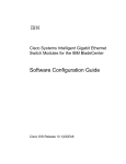
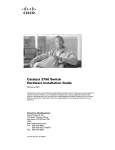
VTP pruning is disabled in the switched network. Port 1 on Switch A and Port 2 on Switch D are assigned to
the Red VLAN. If a broadcast is sent from the host connected to Switch A, Switch A floods the broadcast
and every switch in the network receives it, even though Switches C, E, and F have no ports in the Red VLAN.
Figure 1: Flooding Traffic without VTP Pruning
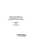
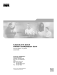
VTP pruning is enabled in the switched network. The broadcast traffic from Switch A is not forwarded to
Switches C, E, and F because traffic for the Red VLAN has been pruned on the links shown (Port 5 on Switch
B and Port 4 on Switch D).
Figure 2: Optimized Flooded Traffic VTP Pruning
Enabling VTP pruning on a VTP server enables pruning for the entire management domain. Making VLANs
pruning-eligible or pruning-ineligible affects pruning eligibility for those VLANs on that trunk only (not on
all switches in the VTP domain).
VTP pruning takes effect several seconds after you enable it. VTP pruning does not prune traffic from VLANs
that are pruning-ineligible. VLAN 1 and VLANs 1002 to 1005 are always pruning-ineligible; traffic from
these VLANs cannot be pruned. Extended-range VLANs (VLAN IDs higher than 1005) are also
pruning-ineligible.
Catalyst 2960-XR Switch VLAN Configuration Guide, Cisco IOS Release 15.0(2)EX1
OL-29440-01
19
Configuring VTP
VTP and Switch Stacks
Related Topics
Enabling VTP Pruning, on page 29
VTP and Switch Stacks
VTP configuration is the same in all members of a switch stack. When the switch stack is in VTP server or
client mode, all switches in the stack carry the same VTP configuration. When VTP mode is transparent, the
stack is not taking part in VTP.
• When a switch joins the stack, it inherits the VTP and VLAN properties of the stack master.
• All VTP updates are carried across the stack.
• When VTP mode is changed in a switch in the stack, the other switches in the stack also change VTP
mode, and the switch VLAN database remains consistent.
VTP version 3 functions the same on a standalone switch or a stack except when the switch stack is the primary
server for the VTP database. In this case, the MAC address of the stack master is used as the primary server
ID. If the master switch reloads or is powered off, a new stack master is elected.
• If you do not configure the persistent MAC address feature (by entering the stack-mac persistent timer
[0 | time-value] global configuration command, when the new master is elected, it sends a takeover
message with the new master MAC address as the primary server.
• If persistent MAC address is configured, the new master waits for the configured stack-mac persistent
timer value. If the previous master switch does not rejoin the stack during this time, then the new master
issues the takeover message.
VTP Configuration Guidelines
Configuration Requirements
When you configure VTP, you must configure a trunk port so that the switch can send and receive VTP
advertisements to and from other switches in the domain.
If you are configuring VTP on a cluster member switch to a VLAN, use the rcommand privileged EXEC
command to log in to the member switch. For more information about the command, see the command
reference for this release.
In VTP versions 1 and 2, when you configure extended-range VLANs on the switch, the switch must be in
VTP transparent mode. VTP version 3 also supports creating extended-range VLANs in client or server mode.
VTP versions 1 and 2 do not support private VLANs. VTP version 3 does support private VLANs. If you
configure private VLANs, the switch must be in VTP transparent mode. When private VLANs are configured
on the switch, do not change the VTP mode from transparent to client or server mode.
VTP Settings
The VTP information is saved in the VTP VLAN database. When VTP mode is transparent, the VTP domain
name and mode are also saved in the switch running configuration file, and you can save it in the switch
Catalyst 2960-XR Switch VLAN Configuration Guide, Cisco IOS Release 15.0(2)EX1
20
OL-29440-01
Configuring VTP
VTP Configuration Guidelines
startup configuration file by entering the copy running-config startup-config privileged EXEC command.
You must use this command if you want to save VTP mode as transparent, even if the switch resets.
When you save VTP information in the switch startup configuration file and reboot the switch, the switch
configuration is selected as follows:
• If the VTP mode is transparent in the startup configuration and the VLAN database and the VTP domain
name from the VLAN database matches that in the startup configuration file, the VLAN database is
ignored (cleared), and the VTP and VLAN configurations in the startup configuration file are used. The
VLAN database revision number remains unchanged in the VLAN database.
• If the VTP mode or domain name in the startup configuration do not match the VLAN database, the
domain name and VTP mode and configuration for VLAN IDs 1 to 1005 use the VLAN database
information.
Domain Names for Configuring VTP
When configuring VTP for the first time, you must always assign a domain name. You must configure all
switches in the VTP domain with the same domain name. Switches in VTP transparent mode do not exchange
VTP messages with other switches, and you do not need to configure a VTP domain name for them.
Note
If the NVRAM and DRAM storage is sufficient, all switches in a VTP domain should be in VTP server
mode.
Caution
Do not configure a VTP domain if all switches are operating in VTP client mode. If you configure the
domain, it is impossible to make changes to the VLAN configuration of that domain. Make sure that you
configure at least one switch in the VTP domain for VTP server mode.
Passwords for the VTP Domain
You can configure a password for the VTP domain, but it is not required. If you do configure a domain
password, all domain switches must share the same password and you must configure the password on each
switch in the management domain. Switches without a password or with the wrong password reject VTP
advertisements.
If you configure a VTP password for a domain, a switch that is booted without a VTP configuration does not
accept VTP advertisements until you configure it with the correct password. After the configuration, the switch
accepts the next VTP advertisement that uses the same password and domain name in the advertisement.
If you are adding a new switch to an existing network with VTP capability, the new switch learns the domain
name only after the applicable password has been configured on it.
Caution
When you configure a VTP domain password, the management domain does not function properly if you
do not assign a management domain password to each switch in the domain.
Catalyst 2960-XR Switch VLAN Configuration Guide, Cisco IOS Release 15.0(2)EX1
OL-29440-01
21
Configuring VTP
VTP Configuration Guidelines
Related Topics
Configuring a VTP Version 3 Password, on page 26
Example: Configuring a Hidden Password, on page 35
VTP Version
Follow these guidelines when deciding which VTP version to implement:
• All switches in a VTP domain must have the same domain name, but they do not need to run the same
VTP version.
• A VTP version 2-capable switch can operate in the same VTP domain as a switch running VTP version
1 if version 2 is disabled on the version 2-capable switch (version 2 is disabled by default).
• If a switch running VTP version 1, but capable of running VTP version 2, receives VTP version 3
advertisements, it automatically moves to VTP version 2.
• If a switch running VTP version 3 is connected to a switch running VTP version 1, the VTP version 1
switch moves to VTP version 2, and the VTP version 3 switch sends scaled-down versions of the VTP
packets so that the VTP version 2 switch can update its database.
• A switch running VTP version 3 cannot move to version 1 or 2 if it has extended VLANs.
• Do not enable VTP version 2 on a switch unless all of the switches in the same VTP domain are
version-2-capable. When you enable version 2 on a switch, all of the version-2-capable switches in the
domain enable version 2. If there is a version 1-only switch, it does not exchange VTP information with
switches that have version 2 enabled.
• Cisco recommends placing VTP version 1 and 2 switches at the edge of the network because they do
not forward VTP version 3 advertisements.
• If there are TrBRF and TrCRF Token Ring networks in your environment, you must enable VTP version
2 or version 3 for Token Ring VLAN switching to function properly. To run Token Ring and Token
Ring-Net, disable VTP version 2.
• VTP version 1 and version 2 do not propagate configuration information for extended range VLANs
(VLANs 1006 to 4094). You must configure these VLANs manually on each device. VTP version 3
supports extended-range VLANs. You cannot convert from VTP version 3 to VTP version 2 if extended
VLANs are configured.
• When a VTP version 3 device trunk port receives messages from a VTP version 2 device, it sends a
scaled-down version of the VLAN database on that particular trunk in VTP version 2 format. A VTP
version 3 device does not send VTP version 2-formatted packets on a trunk unless it first receives VTP
version 2 packets on that trunk port.
• When a VTP version 3 device detects a VTP version 2 device on a trunk port, it continues to send VTP
version 3 packets, in addition to VTP version 2 packets, to allow both kinds of neighbors to coexist on
the same trunk.
• A VTP version 3 device does not accept configuration information from a VTP version 2 or version 1
device.
• Two VTP version 3 regions can only communicate in transparent mode over a VTP version 1 or version
2 region.
• Devices that are only VTP version 1 capable cannot interoperate with VTP version 3 devices.
Catalyst 2960-XR Switch VLAN Configuration Guide, Cisco IOS Release 15.0(2)EX1
22
OL-29440-01
Configuring VTP
Default VTP Configuration
• For VTP version 1 and version 2, if extended-range VLANs are configured on the switch stack, you
cannot change VTP mode to client or server. You receive an error message, and the configuration is not
allowed. VTP version 1 and version 2 do not propagate configuration information for extended range
VLANs (VLANs 1006 to 4094). You must manually configure these VLANs on each device.
Note
For VTP version 1 and 2, before you create extended-range VLANs (VLAN IDs 1006
to 4094), you must set VTP mode to transparent by using the vtp mode transparent
global configuration command. Save this configuration to the startup configuration so
that the switch starts in VTP transparent mode. Otherwise, you lose the extended-range
VLAN configuration if the switch resets and boots up in VTP server mode (the default).
• VTP version 3 supports extended-range VLANs. If extended VLANs are configured, you cannot convert
from VTP version 3 to VTP version 2.
• If you configure the switch for VTP client mode, the switch does not create the VLAN database file
(vlan.dat). If the switch is then powered off, it resets the VTP configuration to the default. To keep the
VTP configuration with VTP client mode after the switch restarts, you must first configure the VTP
domain name before the VTP mode.
Caution
If all switches are operating in VTP client mode, do not configure a VTP domain name.
If you do, it is impossible to make changes to the VLAN configuration of that domain.
Therefore, make sure you configure at least one switch as a VTP server.
Related Topics
Enabling the VTP Version, on page 28
Default VTP Configuration
The following table shows the default VTP configuration.
Table 5: Default VTP Configuration
Feature
Default Setting
VTP domain name
Null
VTP mode (VTP version 1 and version 2)
Server
VTP mode (VTP version 3)
The mode is the same as the mode in VTP version 1
or 2 before conversion to version 3.
VTP version
Version 1
MST database mode
Transparent
VTP version 3 server type
Secondary
Catalyst 2960-XR Switch VLAN Configuration Guide, Cisco IOS Release 15.0(2)EX1
OL-29440-01
23
Configuring VTP
How to Configure VTP
Feature
Default Setting
VTP password
None
VTP pruning
Disabled
How to Configure VTP
Configuring VTP Mode
You can configure VTP mode as one of these:
• When a switch is in VTP server mode, you can change the VLAN configuration and have it propagated
throughout the network.
• When a switch is in VTP client mode, you cannot change its VLAN configuration. The client switch
receives VTP updates from a VTP server in the VTP domain and then modifies its configuration
accordingly.
• When you configure the switch for VTP transparent mode, VTP is disabled on the switch. The switch
does not send VTP updates and does not act on VTP updates received from other switch. However, a
VTP transparent switch running VTP version 2 does forward received VTP advertisements on its trunk
links.
• VTP off mode is the same as VTP transparent mode except that VTP advertisements are not forwarded.
When you configure a domain name, it cannot be removed; you can only reassign a switch to a different
domain.
SUMMARY STEPS
1. configure terminal
2. vtp domain domain-name
3. vtp mode {client | server | transparent | off} {vlan | mst | unknown}
4. vtp password password
5. end
6. show vtp status
7. copy running-config startup-config
Catalyst 2960-XR Switch VLAN Configuration Guide, Cisco IOS Release 15.0(2)EX1
24
OL-29440-01
Configuring VTP
Configuring VTP Mode
DETAILED STEPS
Step 1
Command or Action
Purpose
configure terminal
Enters the global configuration mode.
Example:
Switch# configure terminal
Step 2
vtp domain domain-name
Example:
Switch(config)# vtp domain
eng_group
Configures the VTP administrative-domain name. The name can be 1 to 32
characters. All switches operating in VTP server or client mode under the
same administrative responsibility must be configured with the same domain
name.
This command is optional for modes other than server mode. VTP server
mode requires a domain name. If the switch has a trunk connection to a VTP
domain, the switch learns the domain name from the VTP server in the domain.
You should configure the VTP domain before configuring other VTP
parameters.
Note
Step 3
vtp mode {client | server | transparent Configures the switch for VTP mode (client, server, transparent, or off).
| off} {vlan | mst | unknown}
• vlan—The VLAN database is the default if none are configured.
Example:
• mst—The multiple spanning tree (MST) database.
Switch(config)# vtp mode server
• unknown—An unknown database type.
Note
Step 4
vtp password password
Example:
Step 5
To return a switch in another mode to VTP server mode, use the no
vtp mode global configuration command.
(Optional) Sets the password for the VTP domain. The password can be 8 to
64 characters. If you configure a VTP password, the VTP domain does not
function properly if you do not assign the same password to each switch in
the domain.
Switch(config)# vtp password
mypassword
Note
end
Returns to privileged EXEC mode.
To return the switch to a no-password state, use the no vtp password
global configuration command.
Example:
Switch(config)# end
Step 6
show vtp status
Verifies your entries in the VTP Operating Mode and the VTP Domain Name
fields of the display.
Example:
Switch# show vtp status
Catalyst 2960-XR Switch VLAN Configuration Guide, Cisco IOS Release 15.0(2)EX1
OL-29440-01
25
Configuring VTP
Configuring a VTP Version 3 Password
Step 7
Command or Action
Purpose
copy running-config startup-config
(Optional) Saves the configuration in the startup configuration file.
Example:
Only VTP mode and domain name are saved in the switch running
configuration and can be copied to the startup configuration file.
Switch# copy running-config
startup-config
Related Topics
VTP Modes, on page 15
Example: Configuring the Switch as a VTP Server, on page 35
Configuring a VTP Version 3 Password
You can configure a VTP version 3 password on the switch.
SUMMARY STEPS
1. configure terminal
2. vtp password password [hidden | secret]
3. end
4. show vtp password
5. copy running-config startup-config
DETAILED STEPS
Step 1
Command or Action
Purpose
configure terminal
Enters the global configuration mode.
Example:
Switch# configure terminal
Step 2
vtp password password [hidden | secret]
Example:
Switch(config)# vtp password mypassword
hidden
(Optional) Sets the password for the VTP domain. The password can
be 8 to 64 characters.
• (Optional) hidden—Saves the secret key generated from the
password string in the nram:vlan.dat file. If you configure a
takeover by configuring a VTP primary server, you are prompted
to reenter the password.
• (Optional) secret—Directly configures the password. The secret
password must contain 32 hexadecimal characters.
Catalyst 2960-XR Switch VLAN Configuration Guide, Cisco IOS Release 15.0(2)EX1
26
OL-29440-01
Configuring VTP
Configuring a VTP Version 3 Primary Server
Command or Action
Purpose
Note
Step 3
To clear the password, enter the no vtp password global
configuration command.
Returns to privileged EXEC mode.
end
Example:
Switch(config)# end
Step 4
Verifies your entries. The output appears like this:
show vtp password
VTP password: 89914640C8D90868B6A0D8103847A733
Example:
Switch# show vtp password
Step 5
copy running-config startup-config
(Optional) Saves the configuration in the startup configuration file.
Example:
Switch# copy running-config
startup-config
Related Topics
Passwords for the VTP Domain, on page 21
Example: Configuring a Hidden Password, on page 35
Configuring a VTP Version 3 Primary Server
When you configure a VTP server as a VTP primary server, the takeover operation starts.
SUMMARY STEPS
1. vtp primary [vlan | mst] [force]
DETAILED STEPS
Command or Action
Step 1
Purpose
vtp primary [vlan | mst] [force] Changes the operational state of a switch from a secondary server (the default) to a
primary server and advertises the configuration to the domain. If the switch password is
configured as hidden, you are prompted to reenter the password.
Example:
Switch# vtp primary vlan
force
• (Optional) vlan—Selects the VLAN database as the takeover feature. This is the
default.
Catalyst 2960-XR Switch VLAN Configuration Guide, Cisco IOS Release 15.0(2)EX1
OL-29440-01
27
Configuring VTP
Enabling the VTP Version
Command or Action
Purpose
• (Optional) mst—Selects the multiple spanning tree (MST) database as the takeover
feature.
• (Optional) force—Overwrites the configuration of any conflicting servers. If you
do not enter force, you are prompted for confirmation before the takeover.
Related Topics
Example: Configuring a VTP Version 3 Primary Server, on page 35
Enabling the VTP Version
VTP version 2 and version 3 are disabled by default.
• When you enable VTP version 2 on a switch , every VTP version 2-capable switch in the VTP domain
enables version 2. To enable VTP version 3, you must manually configure it on each switch
• With VTP versions 1 and 2, you can configure the version only on switches in VTP server or transparent
mode. If a switch is running VTP version 3, you can change to version 2 when the switch is in client
mode if no extended VLANs exist, no private VLANs exist, and no hidden password was configured.
Caution
VTP version 1 and VTP version 2 are not interoperable on switches in the same VTP
domain. Do not enable VTP version 2 unless every switch in the VTP domain supports
version 2.
• In TrCRF and TrBRF Token Ring environments, you must enable VTP version 2 or VTP version 3 for
Token Ring VLAN switching to function properly. For Token Ring and Token Ring-Net media, disable
VTP version 2.
Caution
In VTP version 3, both the primary and secondary servers can exist on an instance in
the domain.
SUMMARY STEPS
1. configure terminal
2. vtp version {1 | 2 | 3}
3. end
4. show vtp status
5. copy running-config startup-config
Catalyst 2960-XR Switch VLAN Configuration Guide, Cisco IOS Release 15.0(2)EX1
28
OL-29440-01
Configuring VTP
Enabling VTP Pruning
DETAILED STEPS
Step 1
Command or Action
Purpose
configure terminal
Enters the global configuration mode.
Example:
Switch# configure terminal
Step 2
vtp version {1 | 2 | 3}
Enables the VTP version on the switch. The default is VTP
version 1.
Example:
Note
Switch(config)# vtp version 2
Step 3
To return to the default VTP version 1, use the no
vtp version global configuration command.
Returns to privileged EXEC mode.
end
Example:
Switch(config)# end
Step 4
Verifies that the configured VTP version is enabled.
show vtp status
Example:
Switch# show vtp status
Step 5
copy running-config startup-config
(Optional) Saves the configuration in the startup configuration
file.
Example:
Switch# copy running-config startup-config
Related Topics
VTP Version, on page 22
Enabling VTP Pruning
Pruning increases available bandwidth by restricting flooded traffic to those trunk links that the traffic must
use to access the destination devices. You can only enable VTP pruning on a switch in VTP server mode.
With VTP versions 1 and 2, when you enable pruning on the VTP server, it is enabled for the entire VTP
domain. In VTP version 3, you must manually enable pruning on each switch in the domain.
Only VLANs included in the pruning-eligible list can be pruned. By default, VLANs 2 through 1001 are
pruning-eligible on trunk ports. Reserved VLANs and extended-range VLANs cannot be pruned.
Catalyst 2960-XR Switch VLAN Configuration Guide, Cisco IOS Release 15.0(2)EX1
OL-29440-01
29
Configuring VTP
Enabling VTP Pruning
Before You Begin
VTP pruning is not designed to function in VTP transparent mode. If one or more switches in the network
are in VTP transparent mode, you should do one of these:
• Turn off VTP pruning in the entire network.
• Turn off VTP pruning by making all VLANs on the trunk of the switch upstream to the VTP transparent
switch pruning ineligible.
To configure VTP pruning on an interface, use the switchport trunk pruning vlan interface configuration
command. VTP pruning operates when an interface is trunking. You can set VLAN pruning-eligibility, whether
or not VTP pruning is enabled for the VTP domain, whether or not any given VLAN exists, and whether or
not the interface is currently trunking.
SUMMARY STEPS
1. configure terminal
2. vtp pruning
3. end
4. show vtp status
DETAILED STEPS
Step 1
Command or Action
Purpose
configure terminal
Enters the global configuration mode.
Example:
Switch# configure terminal
Step 2
Step 3
vtp pruning
Enables pruning in the VTP administrative domain.
Example:
By default, pruning is disabled. You need to enable pruning on only
one switch in VTP server mode.
Switch(config)# vtp pruning
Note
end
Returns to privileged EXEC mode.
To disable VTP pruning, use the no vtp pruning global
configuration command.
Example:
Switch(config)# end
Step 4
show vtp status
Verifies your entries in the VTP Pruning Mode field of the display.
Example:
Switch# show vtp status
Catalyst 2960-XR Switch VLAN Configuration Guide, Cisco IOS Release 15.0(2)EX1
30
OL-29440-01
Configuring VTP
Configuring VTP on a Per-Port Basis
Related Topics
VTP Pruning, on page 18
Configuring VTP on a Per-Port Basis
With VTP version 3, you can enable or disable VTP on a per-port basis. You can enable VTP only on ports
that are in trunk mode. Incoming and outgoing VTP traffic are blocked, not forwarded.
SUMMARY STEPS
1. configure terminal
2. interface interface-id
3. vtp
4. end
5. show running-config interface interface-id
6. show vtp status
DETAILED STEPS
Step 1
Command or Action
Purpose
configure terminal
Enters the global configuration mode.
Example:
Switch# configure terminal
Step 2
interface interface-id
Identifies an interface, and enters interface configuration
mode.
Example:
Switch(config)# interface gigabitethernet1/0/1
Step 3
vtp
Enables VTP on the specified port.
Note
Example:
To disable VTP on the interface, use the no
vtp interface configuration command.
Switch(config)# vtp
Step 4
end
Returns to privileged EXEC mode.
Example:
Switch(config)# end
Catalyst 2960-XR Switch VLAN Configuration Guide, Cisco IOS Release 15.0(2)EX1
OL-29440-01
31
Configuring VTP
Adding a VTP Client Switch to a VTP Domain
Step 5
Command or Action
Purpose
show running-config interface interface-id
Verifies the change to the port.
Example:
Switch# show running-config interface
gigabitethernet1/0/1
Step 6
show vtp status
Verifies the configuration.
Example:
Switch# show vtp status
Related Topics
Example: Configuring VTP on a Per-Port Basis, on page 36
Adding a VTP Client Switch to a VTP Domain
Follow these steps to verify and reset the VTP configuration revision number on a switch before adding it to
a VTP domain.
Before You Begin
Before adding a VTP client to a VTP domain, always verify that its VTP configuration revision number is
lower than the configuration revision number of the other switches in the VTP domain. Switches in a VTP
domain always use the VLAN configuration of the switch with the highest VTP configuration revision number.
With VTP versions 1 and 2, adding a switch that has a revision number higher than the revision number in
the VTP domain can erase all VLAN information from the VTP server and VTP domain. With VTP version
3, the VLAN information is not erased.
You can use the vtp mode transparent global configuration command to disable VTP on the switch and then
to change its VLAN information without affecting the other switches in the VTP domain.
SUMMARY STEPS
1. show vtp status
2. configure terminal
3. vtp domain domain-name
4. end
5. show vtp status
6. configure terminal
7. vtp domain domain-name
8. end
9. show vtp status
Catalyst 2960-XR Switch VLAN Configuration Guide, Cisco IOS Release 15.0(2)EX1
32
OL-29440-01
Configuring VTP
Adding a VTP Client Switch to a VTP Domain
DETAILED STEPS
Step 1
Command or Action
Purpose
show vtp status
Checks the VTP configuration revision number.
If the number is 0, add the switch to the VTP domain.
Example:
If the number is greater than 0, follow these sub steps:
Switch# show vtp status
• Write down the domain name.
• Write down the configuration revision number.
• Continue with the next steps to reset the switch configuration
revision number.
Step 2
Enters the global configuration mode.
configure terminal
Example:
Switch# configure terminal
Step 3
vtp domain domain-name
Changes the domain name from the original one displayed in Step
1 to a new name.
Example:
Switch(config)# vtp domain domain123
Step 4
Returns to privileged EXEC mode. The VLAN information on the
switch is updated and the configuration revision number is reset to
0.
end
Example:
Switch(config)# end
Step 5
Verifies that the configuration revision number has been reset to 0.
show vtp status
Example:
Switch# show vtp status
Step 6
Enters global configuration mode.
configure terminal
Example:
Switch# configure terminal
Step 7
vtp domain domain-name
Enters the original domain name on the switch
Example:
Switch(config)# vtp domain domain012
Catalyst 2960-XR Switch VLAN Configuration Guide, Cisco IOS Release 15.0(2)EX1
OL-29440-01
33
Configuring VTP
Monitoring VTP
Step 8
Command or Action
Purpose
end
Returns to privileged EXEC mode. The VLAN information on the
switch is updated.
Example:
Switch(config)# end
Step 9
show vtp status
(Optional) Verifies that the domain name is the same as in Step 1
and that the configuration revision number is 0.
Example:
Switch# show vtp status
Related Topics
VTP Domain, on page 14
Monitoring VTP
This section describes commands used to display and monitor the VTP configuration.
You monitor VTP by displaying VTP configuration information: the domain name, the current VTP revision,
and the number of VLANs. You can also display statistics about the advertisements sent and received by the
switch.
Table 6: VTP Monitoring Commands
Command
Purpose
show vtp counters
Displays counters about VTP messages that have been
sent and received.
show vtp devices [conflict]
Displays information about all VTP version 3 devices in
the domain. Conflicts are VTP version 3 devices with
conflicting primary servers. The show vtp devices
command does not display information when the switch
is in transparent or off mode.
show vtp interface [interface-id]
Displays VTP status and configuration for all interfaces
or the specified interface.
show vtp password
Displays the VTP password. The form of the password
displayed depends on whether or not the hidden keyword
was entered and if encryption is enabled on the switch.
show vtp status
Displays the VTP switch configuration information.
Catalyst 2960-XR Switch VLAN Configuration Guide, Cisco IOS Release 15.0(2)EX1
34
OL-29440-01
Configuring VTP
Configuration Examples for VTP
Configuration Examples for VTP
Example: Configuring the Switch as a VTP Server
This example shows how to configure the switch as a VTP server with the domain name eng_group and the
password mypassword:
Switch(config)# vtp domain eng_group
Setting VTP domain name to eng_group.
Switch(config)# vtp mode server
Setting device to VTP Server mode for VLANS.
Switch(config)# vtp password mypassword
Setting device VLAN database password to mypassword.
Switch(config)# end
Related Topics
Configuring VTP Mode, on page 24
VTP Modes, on page 15
Example: Configuring a Hidden Password
This example shows how to configure a hidden password and how it appears.
Switch(config)# vtp password mypassword hidden
Generating the secret associated to the password.
Switch(config)# end
Switch# show vtp password
VTP password: 89914640C8D90868B6A0D8103847A733
Related Topics
Configuring a VTP Version 3 Password, on page 26
Passwords for the VTP Domain, on page 21
Example: Configuring a VTP Version 3 Primary Server
This example shows how to configure a switch as the primary server for the VLAN database (the default)
when a hidden or secret password was configured:
Switch# vtp primary vlan
Enter VTP password: mypassword
This switch is becoming Primary server for vlan feature in the VTP domain
VTP Database Conf Switch ID Primary Server Revision System Name
------------ ---- -------------- -------------- -------- --------------------
Catalyst 2960-XR Switch VLAN Configuration Guide, Cisco IOS Release 15.0(2)EX1
OL-29440-01
35
Configuring VTP
Example: Configuring VTP on a Per-Port Basis
VLANDB Yes 00d0.00b8.1400=00d0.00b8.1400 1 stp7
Do you want to continue (y/n) [n]? y
Related Topics
Configuring a VTP Version 3 Primary Server, on page 27
Example: Configuring VTP on a Per-Port Basis
This example shows how to configure VTP on a per-port basis:
Switch(config)# interface gigabitethernet 1/0/1
Switch(config-if)# vtp
Switch(config-if)# end
Related Topics
Configuring VTP on a Per-Port Basis, on page 31
Where to Go Next
After configuring VTP, you can configure the following:
• VLANs
• VLAN trunking
• Private VLANs
• VLAN Membership Policy Server (VMPS)
• Tunneling
• Voice VLANs
Additional References
Related Documents
Related Topic
Document Title
For complete syntax and usage information for the
commands used in this chapter.
Catalyst 2960-XR Switch VLAN Management
Command Reference
Standards and RFCs
Standard/RFC
Title
—
—
Catalyst 2960-XR Switch VLAN Configuration Guide, Cisco IOS Release 15.0(2)EX1
36
OL-29440-01
Configuring VTP
Feature History and Information for VTP
MIBs
MIB
MIBs Link
All supported MIBs for this release.
To locate and download MIBs for selected platforms,
Cisco IOS releases, and feature sets, use Cisco MIB
Locator found at the following URL:
http://www.cisco.com/go/mibs
Technical Assistance
Description
Link
The Cisco Support website provides extensive online http://www.cisco.com/support
resources, including documentation and tools for
troubleshooting and resolving technical issues with
Cisco products and technologies.
To receive security and technical information about
your products, you can subscribe to various services,
such as the Product Alert Tool (accessed from Field
Notices), the Cisco Technical Services Newsletter,
and Really Simple Syndication (RSS) Feeds.
Access to most tools on the Cisco Support website
requires a Cisco.com user ID and password.
Feature History and Information for VTP
Release
Modification
Cisco IOS 15.0(2)EX1
This feature was introduced.
Catalyst 2960-XR Switch VLAN Configuration Guide, Cisco IOS Release 15.0(2)EX1
OL-29440-01
37
Configuring VTP
Feature History and Information for VTP
Catalyst 2960-XR Switch VLAN Configuration Guide, Cisco IOS Release 15.0(2)EX1
38
OL-29440-01
CHAPTER
3
Configuring VLANs
• Finding Feature Information, page 39
• Prerequisites for VLANs, page 39
• Restrictions for VLANs, page 40
• Information About VLANs, page 40
• How to Configure VLANs, page 47
• Monitoring VLANs, page 56
• Configuration Examples, page 57
• Where to Go Next, page 58
• Additional References, page 58
• Feature History and Information for VLAN, page 59
Finding Feature Information
Your software release may not support all the features documented in this module. For the latest feature
information and caveats, see the release notes for your platform and software release.
Use Cisco Feature Navigator to find information about platform support and Cisco software image support.
To access Cisco Feature Navigator, go to http://www.cisco.com/go/cfn. An account on Cisco.com is not
required.
Prerequisites for VLANs
The following are prerequisites and considerations for configuring VLANs:
• The switch supports 1005 VLANs when running the IP Lite image.
• The switch supports 256 SVIs when running the IP Lite image.
Catalyst 2960-XR Switch VLAN Configuration Guide, Cisco IOS Release 15.0(2)EX1
OL-29440-01
39
Configuring VLANs
Restrictions for VLANs
Restrictions for VLANs
The following are the restrictions for configuring VLANs:
• The switch supports homogeneous stacking, but does not support mixed stacking.
Information About VLANs
Logical Networks
A VLAN is a switched network that is logically segmented by function, project team, or application, without
regard to the physical locations of the users. VLANs have the same attributes as physical LANs, but you can
group end stations even if they are not physically located on the same LAN segment. Any switch port can
belong to a VLAN, and unicast, broadcast, and multicast packets are forwarded and flooded only to end
stations in the VLAN. Each VLAN is considered a logical network, and packets destined for stations that do
not belong to the VLAN must be forwarded through a router or a switch supporting fallback bridging. In a
switch stack, VLANs can be formed with ports across the stack. Because a VLAN is considered a separate
logical network, it contains its own bridge Management Information Base (MIB) information and can support
its own implementation of spanning tree.
Figure 3: VLANs as Logically Defined Networks
VLANs are often associated with IP subnetworks. For example, all the end stations in a particular IP subnet
belong to the same VLAN. Interface VLAN membership on the switch is assigned manually on an
Catalyst 2960-XR Switch VLAN Configuration Guide, Cisco IOS Release 15.0(2)EX1
40
OL-29440-01
Configuring VLANs
Supported VLANs
interface-by-interface basis. When you assign switch interfaces to VLANs by using this method, it is known
as interface-based, or static, VLAN membership.
Traffic between VLANs must be routed or fallback bridged.
The switch can route traffic between VLANs by using switch virtual interfaces (SVIs). An SVI must be
explicitly configured and assigned an IP address to route traffic between VLANs.
Supported VLANs
The switch supports VLANs in VTP client, server, and transparent modes. VLANs are identified by a number
from 1 to 4094. VLAN IDs 1002 through 1005 are reserved for Token Ring and FDDI VLANs. VTP version
1 and version 2 support only normal-range VLANs (VLAN IDs 1 to 1005). In these versions, the switch must
be in VTP transparent mode when you create VLAN IDs from 1006 to 4094. VTP version 3 supports the
entire VLAN range (VLANs 1 to 4094). Extended range VLANs (VLANs 1006 to 4094) are supported only
in VTP version 3. You cannot convert from VTP version 3 to VTP version 2 if extended VLANs are configured
in the domain.
The switch or switch stack supports a total of 1005 (normal range and extended range) VLANs. However,
the number of routed ports, SVIs, and other configured features affects the use of the switch hardware.
The switch supports per-VLAN spanning-tree plus (PVST+) or rapid PVST+ with a maximum of 128
spanning-tree instances. One spanning-tree instance is allowed per VLAN.
The switch supports IEEE 802.1Q trunking methods for sending VLAN traffic over Ethernet ports.
VLAN Port Membership Modes
You configure a port to belong to a VLAN by assigning a membership mode that specifies the kind of traffic
the port carries and the number of VLANs to which it can belong.
When a port belongs to a VLAN, the switch learns and manages the addresses associated with the port on a
per-VLAN basis.
Table 7: Port Membership Modes and Characteristics
Membership Mode
VLAN Membership Characteristics VTP Characteristics
Static-access
A static-access port can belong to VTP is not required. If you do not
one VLAN and is manually
want VTP to globally propagate
assigned to that VLAN.
information, set the VTP mode to
transparent. To participate in VTP,
there must be at least one trunk port
on the switch or the switch stack
connected to a trunk port of a
second switch or switch stack.
Catalyst 2960-XR Switch VLAN Configuration Guide, Cisco IOS Release 15.0(2)EX1
OL-29440-01
41
Configuring VLANs
Normal-Range VLAN Overview
Membership Mode
VLAN Membership Characteristics VTP Characteristics
Trunk (IEEE 802.1Q) :
A trunk port is a member of all
VLANs by default, including
extended-range VLANs, but
membership can be limited by
configuring the allowed-VLAN
list. You can also modify the
pruning-eligible list to block
flooded traffic to VLANs on trunk
ports that are included in the list.
VTP is recommended but not
required. VTP maintains VLAN
configuration consistency by
managing the addition, deletion,
and renaming of VLANs on a
network-wide basis. VTP
exchanges VLAN configuration
messages with other switches over
trunk links.
A dynamic-access port can belong
to one VLAN (VLAN ID 1 to
4094) and is dynamically assigned
by a VLAN Member Policy Server
(VMPS).
VTP is required.
• IEEE 802.1Q—
Industry-standard trunking
encapsulation.
Dynamic access
Configure the VMPS and the client
with the same VTP domain name.
To participate in VTP, at least one
trunk port on the switch or a switch
The VMPS can be a Catalyst 6500 stack must be connected to a trunk
series switch, for example, but
port of a second switch or switch
never a Catalyst 2960, 2960-S, or stack.
2960-C switch. The Catalyst 2960,
2960-S, or 2960-C switch is a
VMPS client.
You can have dynamic-access ports
and trunk ports on the same switch,
but you must connect the
dynamic-access port to an end
station or hub and not to another
switch.
Voice VLAN
A voice VLAN port is an access VTP is not required; it has no effect
port attached to a Cisco IP Phone, on a voice VLAN.
configured to use one VLAN for
voice traffic and another VLAN for
data traffic from a device attached
to the phone.
Normal-Range VLAN Overview
Normal-range VLANs are VLANs with VLAN IDs 1 to 1005. If the switch is in VTP server or VTP transparent
mode, you can add, modify or remove configurations for VLANs 2 to 1001 in the VLAN database. (VLAN
IDs 1 and 1002 to 1005 are automatically created and cannot be removed.)
In VTP versions 1 and 2, the switch must be in VTP transparent mode when you create extended-range VLANs
(VLANs with IDs from 1006 to 4094), but these VLANs are not saved in the VLAN database. VTP version
3 supports extended-range VLANs in VTP server and transparent mode.
Configurations for VLAN IDs 1 to 1005 are written to the file vlan.dat (VLAN database), and you can display
them by entering the show vlan privileged EXEC command. The vlan.dat file is stored in flash memory. On
Catalyst 2960-XR Switch VLAN Configuration Guide, Cisco IOS Release 15.0(2)EX1
42
OL-29440-01
Configuring VLANs
VLAN Configuration Saving Process
a switch, the vlan.dat file is stored in flash memory on the stack master. Stack members have a vlan.dat file
that is consistent with the stack master.
Token Ring VLANs
Although the switch does not support Token Ring connections, a remote device such as a Catalyst 5000 series
switch with Token Ring connections could be managed from one of the supported switches. Switches running
VTP Version 2 advertise information about these Token Ring VLANs:
• Token Ring TrBRF VLANs
• Token Ring TrCRF VLANs
Note
For more information on configuring Token Ring VLANs, see the Catalyst 5000 Series Software
Configuration Guide.
Normal-Range VLANs Configuration Process
You configure VLANs in the vlan global configuration command by entering a VLAN ID. Enter a new
VLAN ID to create a VLAN, or enter an existing VLAN ID to modify that VLAN. You can use the default
VLAN configuration or enter multiple commands to configure the VLAN. For more information about
commands available in this mode, see the vlan global configuration command description in the command
reference for this release. When you have finished the configuration, you must exit VLAN configuration mode
for the configuration to take effect. To display the VLAN configuration, enter the show vlan privileged EXEC
command.
VLAN Configuration Saving Process
The configurations of VLAN IDs 1 to 1005 are always saved in the VLAN database (vlan.dat file). If the VTP
mode is transparent, they are also saved in the switch running configuration file. You can enter the copy
running-config startup-config privileged EXEC command to save the configuration in the startup configuration
file. In a switch stack, the whole stack uses the same vlan.dat file and running configuration. To display the
VLAN configuration, enter the show vlan privileged EXEC command.
When you save VLAN and VTP information (including extended-range VLAN configuration information)
in the startup configuration file and reboot the switch, the switch configuration is selected as follows:
• If the VTP mode is transparent in the startup configuration, and the VLAN database and the VTP domain
name from the VLAN database matches that in the startup configuration file, the VLAN database is
ignored (cleared), and the VTP and VLAN configurations in the startup configuration file are used. The
VLAN database revision number remains unchanged in the VLAN database.
• If the VTP mode or domain name in the startup configuration does not match the VLAN database, the
domain name and VTP mode and configuration for the VLAN IDs 1 to 1005 use the VLAN database
information.
• In VTP versions 1 and 2, if VTP mode is server, the domain name and VLAN configuration for VLAN
IDs 1 to 1005 use the VLAN database information. VTP version 3 also supports VLANs 1006 to 4094.
Catalyst 2960-XR Switch VLAN Configuration Guide, Cisco IOS Release 15.0(2)EX1
OL-29440-01
43
Configuring VLANs
Normal-Range VLAN Configuration Guidelines
Normal-Range VLAN Configuration Guidelines
Normal-range VLANs are VLANs with IDs from 1 to 1005. VTP 1 and 2 only support normal-range VLANs.
Follow these guidelines when creating and modifying normal-range VLANs in your network:
• Normal-range VLANs are identified with a number between 1 and 1001. VLAN numbers 1002 through
1005 are reserved for Token Ring and FDDI VLANs.
• VLAN configuration for VLANs 1 to 1005 are always saved in the VLAN database. If the VTP mode
is transparent, VTP and VLAN configuration are also saved in the switch running configuration file.
• If the switch is in VTP server or VTP transparent mode, you can add, modify or remove configurations
for VLANs 2 to 1001 in the VLAN database. (VLAN IDs 1 and 1002 to 1005 are automatically created
and cannot be removed.)
• With VTP versions 1 and 2, the switch supports VLAN IDs 1006 through 4094 only in VTP transparent
mode (VTP disabled). These are extended-range VLANs and configuration options are limited.
Extended-range VLANs created in VTP transparent mode are not saved in the VLAN database and are
not propagated. VTP version 3 supports extended range VLAN (VLANs 1006 to 4094) database
propagation in VTP server and transparent mode. If extended VLANs are configured, you cannot convert
from VTP version 3 to version 1 or 2.
• Before you can create a VLAN, the switch must be in VTP server mode or VTP transparent mode. If
the switch is a VTP server, you must define a VTP domain or VTP will not function.
• The switch does not support Token Ring or FDDI media. The switch does not forward FDDI, FDDI-Net,
TrCRF, or TrBRF traffic, but it does propagate the VLAN configuration through VTP.
• The switch supports 128 spanning tree instances. If a switch has more active VLANs than supported
spanning-tree instances, spanning tree can be enabled on 128 VLANs and is disabled on the remaining
VLANs. If you have already used all available spanning-tree instances on a switch, adding another
VLAN anywhere in the VTP domain creates a VLAN on that switch that is not running spanning-tree.
If you have the default allowed list on the trunk ports of that switch (which is to allow all VLANs), the
new VLAN is carried on all trunk ports. Depending on the topology of the network, this could create a
loop in the new VLAN that would not be broken, particularly if there are several adjacent switches that
all have run out of spanning-tree instances. You can prevent this possibility by setting allowed lists on
the trunk ports of switches that have used up their allocation of spanning-tree instances.
If the number of VLANs on the switch exceeds the number of supported spanning-tree instances, we
recommend that you configure the IEEE 802.1s Multiple STP (MSTP) on your switch to map multiple
VLANs to a single spanning-tree instance.
• When a switch in a stack learns a new VLAN or deletes or modifies an existing VLAN (either through
VTP over network ports or through the CLI), the VLAN information is communicated to all stack
members.
• When a switch joins a stack or when stacks merge, VTP information (the vlan.dat file) on the new
switches will be consistent with the active switch.
Related Topics
Creating or Modifying an Ethernet VLAN, on page 47
Example: Creating a VLAN Name, on page 57
Catalyst 2960-XR Switch VLAN Configuration Guide, Cisco IOS Release 15.0(2)EX1
44
OL-29440-01
Configuring VLANs
Extended-Range VLAN Configuration Guidelines
Extended-Range VLAN Configuration Guidelines
VTP 3 only supports extended-range VLANs. Extended-range VLANs are VLANs with IDs from 1006 to
4094.
Follow these guidelines when creating extended-range VLANs:
• VLAN IDs in the extended range are not saved in the VLAN database and are not recognized by VTP
unless the switch is running VTP version 3.
• You cannot include extended-range VLANs in the pruning eligible range.
• In VTP version 1 and 2, a switch must be in VTP transparent mode when you create extended-range
VLANs. If VTP mode is server or client, an error message is generated, and the extended-range VLAN
is rejected. VTP version 3 supports extended VLANs in server and transparent modes.
• For VTP version 1 or 2, you can set the VTP mode to transparent in global configuration mode. You
should save this configuration to the startup configuration so that the switch boots up in VTP transparent
mode. Otherwise, you lose the extended-range VLAN configuration if the switch resets. If you create
extended-range VLANs in VTP version 3, you cannot convert to VTP version 1 or 2.
• STP is enabled by default on extended-range VLANs, but you can disable it by using the no spanning-tree
vlan vlan-id global configuration command. When the maximum number of spanning-tree instances
are on the switch, spanning tree is disabled on any newly created VLANs. If the number of VLANs on
the switch exceeds the maximum number of spanning-tree instances, we recommend that you configure
the IEEE 802.1s Multiple STP (MSTP) on your switch to map multiple VLANs to a single spanning-tree
instance.
• Each routed port on the switch creates an internal VLAN for its use. These internal VLANs use
extended-range VLAN numbers, and the internal VLAN ID cannot be used for an extended-range VLAN.
If you try to create an extended-range VLAN with a VLAN ID that is already allocated as an internal
VLAN, an error message is generated, and the command is rejected.
◦Because internal VLAN IDs are in the lower part of the extended range, we recommend that you
create extended-range VLANs beginning from the highest number (4094) and moving to the lowest
(1006) to reduce the possibility of using an internal VLAN ID.
◦Before configuring extended-range VLANs, enter the show vlan internal usage privileged EXEC
command to see which VLANs have been allocated as internal VLANs.
◦If necessary, you can shut down the routed port assigned to the internal VLAN, which frees up the
internal VLAN, and then create the extended-range VLAN and re-enable the port, which then uses
another VLAN as its internal VLAN.
• Although the switch or switch stack supports a total of 1005 (normal-range and extended-range) VLANs,
the number of routed ports, SVIs, and other configured features affects the use of the switch hardware.
If you try to create an extended-range VLAN and there are not enough hardware resources available,
an error message is generated, and the extended-range VLAN is rejected.
• In a switch stack, the whole stack uses the same running configuration and saved configuration, and
extended-range VLAN information is shared across the stack.
Related Topics
Creating an Extended-Range VLAN, on page 52
Catalyst 2960-XR Switch VLAN Configuration Guide, Cisco IOS Release 15.0(2)EX1
OL-29440-01
45
Configuring VLANs
Default Ethernet VLAN Configuration
Example: Creating an Extended-Range VLAN, on page 57
Default Ethernet VLAN Configuration
The following table displays the default configuration for Ethernet VLANs.
Note
The switch supports Ethernet interfaces exclusively. Because FDDI and Token Ring VLANs are not
locally supported, you only configure FDDI and Token Ring media-specific characteristics for VTP global
advertisements to other switches.
Table 8: Ethernet VLAN Defaults and Range
Parameter
Default
Range
VLAN ID
1
1 to 4094.
Note
Extended-range VLANs
(VLAN IDs 1006 to 4094)
are only saved in the
VLAN database in VTP
version 3.
VLAN name
VLANxxxx, where xxxx represents No range
four numeric digits (including
leading zeros) equal to the VLAN
ID number
IEEE 802.10 SAID
100001 (100000 plus the VLAN
ID)
1 to 4294967294
MTU Size
1500
576-18190
Translational bridge 1
0
0 to 1005
Translational bridge 2
0
0 to 1005
VLAN state
active
active, suspend
Remote SPAN
disabled
enabled, disabled
Private VLANs
none configured
2 to 1001, 1006 to 4094
Default VLAN Configuration
You can change only the MTU size, private VLAN, and the remote SPAN configuration state on extended-range
VLANs; all other characteristics must remain at the default state.
Catalyst 2960-XR Switch VLAN Configuration Guide, Cisco IOS Release 15.0(2)EX1
46
OL-29440-01
Configuring VLANs
How to Configure VLANs
How to Configure VLANs
How to Configure Normal-Range VLANs
You can set these parameters when you create a new normal-range VLAN or modify an existing VLAN in
the VLAN database:
• VLAN ID
• VLAN name
• VLAN type
◦Ethernet
◦Fiber Distributed Data Interface [FDDI]
◦FDDI network entity title [NET]
◦TrBRF or TrCRF
◦Token Ring
◦Token Ring-Net
• VLAN state (active or suspended)
• Maximum transmission unit (MTU) for the VLAN
• Security Association Identifier (SAID)
• Bridge identification number for TrBRF VLANs
• Ring number for FDDI and TrCRF VLANs
• Parent VLAN number for TrCRF VLANs
• Spanning Tree Protocol (STP) type for TrCRF VLANs
• VLAN number to use when translating from one VLAN type to another
You can cause inconsistency in the VLAN database if you attempt to manually delete the vlan.dat file. If you
want to modify the VLAN configuration, follow the procedures in this section.
Creating or Modifying an Ethernet VLAN
Each Ethernet VLAN in the VLAN database has a unique, 4-digit ID that can be a number from 1 to 1001.
VLAN IDs 1002 to 1005 are reserved for Token Ring and FDDI VLANs. To create a normal-range VLAN
to be added to the VLAN database, assign a number and name to the VLAN.
Note
With VTP version 1 and 2, if the switch is in VTP transparent mode, you can assign VLAN IDs greater
than 1006, but they are not added to the VLAN database.
Catalyst 2960-XR Switch VLAN Configuration Guide, Cisco IOS Release 15.0(2)EX1
OL-29440-01
47
Configuring VLANs
How to Configure Normal-Range VLANs
SUMMARY STEPS
1. configure terminal
2. vlan vlan-id
3. name vlan-name
4. mtu mtu-size
5. remote-span
6. end
7. show vlan {name vlan-name | id vlan-id}
DETAILED STEPS
Step 1
Command or Action
Purpose
configure terminal
Enters the global configuration mode.
Example:
Switch# configure terminal
Step 2
Step 3
vlan vlan-id
Example:
Enters a VLAN ID, and enters VLAN configuration mode. Enter a
new VLAN ID to create a VLAN, or enter an existing VLAN ID to
modify that VLAN.
Switch(config)# vlan 20
Note
name vlan-name
Example:
The available VLAN ID range for this command is 1 to
4094.
(Optional) Enters a name for the VLAN. If no name is entered for
the VLAN, the default is to append the vlan-id value with leading
zeros to the word VLAN. For example, VLAN0004 is a default VLAN
name for VLAN 4.
Switch(config-vlan)# name test20
Step 4
mtu mtu-size
(Optional) Changes the MTU size (or other VLAN characteristic).
Example:
Switch(config-vlan)# mtu 256
Step 5
remote-span
(Optional) Configures the VLAN as the RSPAN VLAN for a remote
SPAN session.
Example:
Note
Switch(config-vlan)# remote-span
Step 6
end
To return the VLAN name to the default settings, use the no
name, no mtu, or no remote-span commands.
Returns to privileged EXEC mode.
Example:
Switch(config)# end
Catalyst 2960-XR Switch VLAN Configuration Guide, Cisco IOS Release 15.0(2)EX1
48
OL-29440-01
Configuring VLANs
How to Configure Normal-Range VLANs
Step 7
Command or Action
Purpose
show vlan {name vlan-name | id vlan-id}
Verifies your entries.
Example:
Switch# show vlan name test20 id 20
Related Topics
Normal-Range VLAN Configuration Guidelines, on page 44
Example: Creating a VLAN Name, on page 57
Deleting a VLAN
When you delete a VLAN from a switch that is in VTP server mode, the VLAN is removed from the VLAN
database for all switches in the VTP domain. When you delete a VLAN from a switch that is in VTP transparent
mode, the VLAN is deleted only on that specific switch or a switch stack.
You cannot delete the default VLANs for the different media types: Ethernet VLAN 1 and FDDI or Token
Ring VLANs 1002 to 1005.
Caution
When you delete a VLAN, any ports assigned to that VLAN become inactive. They remain associated
with the VLAN (and thus inactive) until you assign them to a new VLAN.
SUMMARY STEPS
1. configure terminal
2. no vlan vlan-id
3. end
4. show vlan brief
DETAILED STEPS
Step 1
Command or Action
Purpose
configure terminal
Enters the global configuration mode.
Example:
Switch# configure terminal
Catalyst 2960-XR Switch VLAN Configuration Guide, Cisco IOS Release 15.0(2)EX1
OL-29440-01
49
Configuring VLANs
How to Configure Normal-Range VLANs
Step 2
Command or Action
Purpose
no vlan vlan-id
Removes the VLAN by entering the VLAN ID.
Example:
Switch(config)# no vlan 4
Step 3
end
Returns to privileged EXEC mode.
Example:
Switch(config)# end
Step 4
show vlan brief
Verifies the VLAN removal.
Example:
Switch# show vlan brief
Assigning Static-Access Ports to a VLAN
You can assign a static-access port to a VLAN without having VTP globally propagate VLAN configuration
information by disabling VTP (VTP transparent mode).
If you are assigning a port on a cluster member switch to a VLAN, first use the rcommand privileged EXEC
command to log in to the cluster member switch.
If you assign an interface to a VLAN that does not exist, the new VLAN is created.
SUMMARY STEPS
1. configure terminal
2. interface interface-id
3. switchport mode access
4. switchport access vlan vlan-id
5. end
6. show running-config interface interface-id
7. show interfaces interface-id switchport
Catalyst 2960-XR Switch VLAN Configuration Guide, Cisco IOS Release 15.0(2)EX1
50
OL-29440-01
Configuring VLANs
How to Configure Normal-Range VLANs
DETAILED STEPS
Step 1
Command or Action
Purpose
configure terminal
Enters the global configuration mode.
Example:
Switch# configure terminal
Step 2
interface interface-id
Enters the interface to be added to the VLAN.
Example:
Switch(config)# interface gigabitethernet2/0/1
Step 3
Defines the VLAN membership mode for the port (Layer
2 access port).
switchport mode access
Example:
Switch(config-if)# switchport mode access
Step 4
switchport access vlan vlan-id
Assigns the port to a VLAN. Valid VLAN IDs are 1 to
4094.
Example:
Note
Switch(config-if)# switchport access vlan 2
Step 5
To return an interface to its default configuration,
use the default interface interface-id interface
configuration command.
Returns to privileged EXEC mode.
end
Example:
Switch(config)# end
Step 6
show running-config interface interface-id
Verifies the VLAN membership mode of the interface.
Example:
Switch# copy running-config startup-config
Step 7
show interfaces interface-id switchport
Verifies your entries in the Administrative Mode and the
Access Mode VLAN fields of the display.
Example:
Switch# show interfaces gigabitethernet2/0/1
Related Topics
Example: Configuring a Port as Access Port, on page 57
Catalyst 2960-XR Switch VLAN Configuration Guide, Cisco IOS Release 15.0(2)EX1
OL-29440-01
51
Configuring VLANs
How to Configure Extended-Range VLANs
How to Configure Extended-Range VLANs
With VTP version 1 and version 2, when the switch is in VTP transparent mode (VTP disabled), you can
create extended-range VLANs (in the range 1006 to 4094). VTP 3 version supports extended-range VLANs
in server or transparent move.
Extended-range VLANs enable service providers to extend their infrastructure to a greater number of customers.
The extended-range VLAN IDs are allowed for any switchport commands that allow VLAN IDs.
With VTP version 1 or 2, extended-range VLAN configurations are not stored in the VLAN database, but
because VTP mode is transparent, they are stored in the switch running configuration file, and you can save
the configuration in the startup configuration file. Extended-range VLANs created in VTP version 3 are stored
in the VLAN database.
You can change only the MTU size, private VLAN, and the remote SPAN configuration state on extended-range
VLANs; all other characteristics must remain at the default state.
Creating an Extended-Range VLAN
You create an extended-range VLAN in global configuration mode by entering the vlan global configuration
command with a VLAN ID from 1006 to 4094. The extended-range VLAN has the default Ethernet VLAN
characteristics and the MTU size, and RSPAN configuration are the only parameters you can change. See the
description of the vlan global configuration command in the command reference for the default settings of
all parameters. In VTP version 1 or 2, if you enter an extended-range VLAN ID when the switch is not in
VTP transparent mode, an error message is generated when you exit VLAN configuration mode, and the
extended-range VLAN is not created.
In VTP version 1 and 2, extended-range VLANs are not saved in the VLAN database; they are saved in the
switch running configuration file. You can save the extended-range VLAN configuration in the switch startup
configuration file by using the copy running-config startup-config privileged EXEC command. VTP version
3 saves extended-range VLANs in the VLAN database.
Note
Before you create an extended-range VLAN, you can verify that the VLAN ID is not used internally by
entering the show vlan internal usage privileged EXEC command. If the VLAN ID is used internally
and you want to free it up, go to the Creating an Extended-Range VLAN with an Internal VLAN ID before
creating the extended-range VLAN.
SUMMARY STEPS
1. configure terminal
2. vtp mode transparent
3. vlan vlan-id
4. mtu mtu size
5. remote-span
6. end
7. show vlan id vlan-id
8. copy running-config startup config
Catalyst 2960-XR Switch VLAN Configuration Guide, Cisco IOS Release 15.0(2)EX1
52
OL-29440-01
Configuring VLANs
How to Configure Extended-Range VLANs
DETAILED STEPS
Step 1
Command or Action
Purpose
configure terminal
Enters the global configuration mode.
Example:
Switch# configure terminal
Step 2
Configures the switch for VTP transparent mode, disabling VTP.
vtp mode transparent
Note
Example:
This step is not required for VTP version
3.
Switch(config)# vtp mode transparent
Step 3
vlan vlan-id
Enters an extended-range VLAN ID and enters VLAN configuration
mode. The range is 1006 to 4094.
Example:
Note
Switch(config)# vlan 2000
Switch(config-vlan)#
Step 4
mtu mtu size
To delete an extended-range VLAN, use the no vlan vlan-id
global configuration command.
Modifies the VLAN by changing the MTU size.
Example:
Switch(config-vlan)# mtu 1024
Step 5
(Optional) Configures the VLAN as the RSPAN VLAN.
remote-span
Example:
Switch(config-vlan)# remote-span
Step 6
Returns to privileged EXEC mode.
end
Example:
Switch(config)# end
Step 7
show vlan id vlan-id
Verifies that the VLAN has been created.
Example:
Switch# show vlan id 2000
Step 8
copy running-config startup config
Saves your entries in the switch startup configuration file.
Example:
To save an extended-range VLAN configuration, you need to save the
VTP transparent mode configuration and the extended-range VLAN
configuration in the switch startup configuration file. Otherwise, if the
Switch# copy running-config
Catalyst 2960-XR Switch VLAN Configuration Guide, Cisco IOS Release 15.0(2)EX1
OL-29440-01
53
Configuring VLANs
How to Configure Extended-Range VLANs
Command or Action
Purpose
startup-config
switch resets, it will default to VTP server mode, and the extended-range
VLAN IDs will not be saved.
Note
This step is not required for VTP version 3 because VLANs
are saved in the VLAN database.
The procedure for assigning static-access ports to an
extended-range VLAN is the same as for normal-range VLANs.
Related Topics
Extended-Range VLAN Configuration Guidelines, on page 45
Example: Creating an Extended-Range VLAN, on page 57
Creating an Extended-Range VLAN with an Internal VLAN ID
If you enter an extended-range VLAN ID that is already assigned to an internal VLAN, an error message is
generated, and the extended-range VLAN is rejected. To manually free an internal VLAN ID, you must
temporarily shut down the routed port that is using the internal VLAN ID.
SUMMARY STEPS
1. show vlan internal usage
2. configure terminal
3. interface interface-id
4. shutdown
5. exit
6. vtp mode transparent
7. vlan vlan-id
8. exit
9. interface interface-id
10. no shutdown
11. end
12. copy running-config startup config
Catalyst 2960-XR Switch VLAN Configuration Guide, Cisco IOS Release 15.0(2)EX1
54
OL-29440-01
Configuring VLANs
How to Configure Extended-Range VLANs
DETAILED STEPS
Step 1
Command or Action
Purpose
show vlan internal usage
Displays the VLAN IDs being used internally by the switch. If the
VLAN ID that you want to use is an internal VLAN, the display
shows the routed port that is using the VLAN ID. Enter that port
number in Step 3.
Example:
Switch# show vlan internal usage
Step 2
Enters global configuration mode.
configure terminal
Example:
Switch# configure terminal
Step 3
interface interface-id
Specifies the interface ID for the routed port that is using the VLAN
ID, and enters interface configuration mode.
Example:
Switch(config)# interface
gigabitethernet1/0/3
Step 4
Shuts down the port to free the internal VLAN ID.
shutdown
Example:
Switch(config-if)# shutdown
Step 5
Returns to global configuration mode.
exit
Example:
Switch(config-if)# exit
Step 6
Sets the VTP mode to transparent for creating extended-range VLANs.
vtp mode transparent
Note
Example:
This step is not required for VTP version
3.
Switch(config)# vtp mode transparent
Step 7
vlan vlan-id
Enters the new extended-range VLAN ID, and enters VLAN
configuration mode.
Example:
Switch(config-vlan)# vlan 2000
Catalyst 2960-XR Switch VLAN Configuration Guide, Cisco IOS Release 15.0(2)EX1
OL-29440-01
55
Configuring VLANs
Monitoring VLANs
Step 8
Command or Action
Purpose
exit
Exits from VLAN configuration mode, and returns to global
configuration mode.
Example:
Switch(config-vlan)# exit
Step 9
interface interface-id
Specifies the interface ID for the routed port that you shut down in
Step 4, and enters interface configuration mode.
Example:
Switch(config)# interface
gigabitethernet1/0/3
Step 10
no shutdown
Reenables the routed port. It will be assigned a new internal VLAN
ID.
Example:
Switch(config)# no shutdown
Step 11
Returns to privileged EXEC mode.
end
Example:
Switch(config)# end
Step 12
copy running-config startup config
Example:
Switch# copy running-config
startup-config
Saves your entries in the switch startup configuration file. To save
an extended-range VLAN configuration, you need to save the VTP
transparent mode configuration and the extended-range VLAN
configuration in the switch startup configuration file. Otherwise, if
the switch resets, it will default to VTP server mode, and the
extended-range VLAN IDs will not be saved.
Note
This step is not required for VTP version 3 because VLANs
are saved in the VLAN database.
Monitoring VLANs
Table 9: Privileged EXEC show Commands
Command
Purpose
show interfaces [vlan vlan-id]
Displays characteristics for all interfaces or for the
specified VLAN configured on the switch.
Catalyst 2960-XR Switch VLAN Configuration Guide, Cisco IOS Release 15.0(2)EX1
56
OL-29440-01
Configuring VLANs
Configuration Examples
Configuration Examples
Example: Creating a VLAN Name
This example shows how to create Ethernet VLAN 20, name it test20, and add it to the VLAN database:
Switch# configure terminal
Switch(config)# vlan 20
Switch(config-vlan)# name test20
Switch(config-vlan)# end
Related Topics
Creating or Modifying an Ethernet VLAN, on page 47
Normal-Range VLAN Configuration Guidelines, on page 44
Example: Configuring a Port as Access Port
This example shows how to configure a port as an access port in VLAN 2:
Switch# configure terminal
Enter configuration commands, one per line. End with CNTL/Z.
Switch(config)# interface gigabitethernet2/0/1
Switch(config-if)# switchport mode access
Switch(config-if)# switchport access vlan 2
Switch(config-if)# end
Related Topics
Assigning Static-Access Ports to a VLAN, on page 50
Example: Creating an Extended-Range VLAN
This example shows how to create a new extended-range VLAN with all default characteristics, enter VLAN
configuration mode, and save the new VLAN in the switch startup configuration file:
Switch(config)# vtp mode transparent
Switch(config)# vlan 2000
Switch(config-vlan)# end
Switch# copy running-config startup config
Related Topics
Creating an Extended-Range VLAN, on page 52
Extended-Range VLAN Configuration Guidelines, on page 45
Catalyst 2960-XR Switch VLAN Configuration Guide, Cisco IOS Release 15.0(2)EX1
OL-29440-01
57
Configuring VLANs
Where to Go Next
Where to Go Next
After configuring VLANs, you can configure the following:
• VLAN Trunking Protocol (VTP)
• VLAN trunks
• Private VLANs
• VLAN Membership Policy Server (VMPS)
• Tunneling
• Voice VLANs
Additional References
Related Documents
Related Topic
Document Title
For complete syntax and usage information for the
commands used in this chapter.
Catalyst 2960-XR Switch VLAN Management
Command Reference
Standards and RFCs
Standard/RFC
Title
—
—
MIBs
MIB
MIBs Link
All supported MIBs for this release.
To locate and download MIBs for selected platforms,
Cisco IOS releases, and feature sets, use Cisco MIB
Locator found at the following URL:
http://www.cisco.com/go/mibs
Catalyst 2960-XR Switch VLAN Configuration Guide, Cisco IOS Release 15.0(2)EX1
58
OL-29440-01
Configuring VLANs
Feature History and Information for VLAN
Technical Assistance
Description
Link
The Cisco Support website provides extensive online http://www.cisco.com/support
resources, including documentation and tools for
troubleshooting and resolving technical issues with
Cisco products and technologies.
To receive security and technical information about
your products, you can subscribe to various services,
such as the Product Alert Tool (accessed from Field
Notices), the Cisco Technical Services Newsletter,
and Really Simple Syndication (RSS) Feeds.
Access to most tools on the Cisco Support website
requires a Cisco.com user ID and password.
Feature History and Information for VLAN
Release
Modification
Cisco IOS 15.0(2)EX1
This feature was introduced.
Catalyst 2960-XR Switch VLAN Configuration Guide, Cisco IOS Release 15.0(2)EX1
OL-29440-01
59
Configuring VLANs
Feature History and Information for VLAN
Catalyst 2960-XR Switch VLAN Configuration Guide, Cisco IOS Release 15.0(2)EX1
60
OL-29440-01
CHAPTER
4
Configuring VLAN Trunks
• Finding Feature Information, page 61
• Prerequisites for VLAN Trunks, page 61
• Restrictions for VLAN Trunks, page 62
• Information About VLAN Trunks, page 62
• How to Configure VLAN Trunks, page 67
• Configuration Examples for VLAN Trunking, page 80
• Where to Go Next, page 81
• Additional References, page 81
• Feature History and Information for VLAN Trunks, page 82
Finding Feature Information
Your software release may not support all the features documented in this module. For the latest feature
information and caveats, see the release notes for your platform and software release.
Use Cisco Feature Navigator to find information about platform support and Cisco software image support.
To access Cisco Feature Navigator, go to http://www.cisco.com/go/cfn. An account on Cisco.com is not
required.
Prerequisites for VLAN Trunks
The IEEE 802.1Q trunks impose these limitations on the trunking strategy for a network:
• In a network of Cisco switches connected through IEEE 802.1Q trunks, the switches maintain one
spanning-tree instance for each VLAN allowed on the trunks. Non-Cisco devices might support one
spanning-tree instance for all VLANs.
When you connect a Cisco switch to a non-Cisco device through an IEEE 802.1Q trunk, the Cisco switch
combines the spanning-tree instance of the VLAN of the trunk with the spanning-tree instance of the
non-Cisco IEEE 802.1Q switch. However, spanning-tree information for each VLAN is maintained by
Catalyst 2960-XR Switch VLAN Configuration Guide, Cisco IOS Release 15.0(2)EX1
OL-29440-01
61
Configuring VLAN Trunks
Restrictions for VLAN Trunks
Cisco switches separated by a cloud of non-Cisco IEEE 802.1Q switches. The non-Cisco IEEE 802.1Q
cloud separating the Cisco switches is treated as a single trunk link between the switches.
• Make sure the native VLAN for an IEEE 802.1Q trunk is the same on both ends of the trunk link. If the
native VLAN on one end of the trunk is different from the native VLAN on the other end, spanning-tree
loops might result.
• Disabling spanning tree on the native VLAN of an IEEE 802.1Q trunk without disabling spanning tree
on every VLAN in the network can potentially cause spanning-tree loops. We recommend that you leave
spanning tree enabled on the native VLAN of an IEEE 802.1Q trunk or disable spanning tree on every
VLAN in the network. Make sure your network is loop-free before disabling spanning tree.
Restrictions for VLAN Trunks
Dynamic Trunking Protocol (DTP) is not supported on private-VLAN ports or tunnel ports.
The switch does not support Layer 3 trunks; you cannot configure subinterfaces or use the encapsulation
keyword on Layer 3 interfaces. The switch does support Layer 2 trunks and Layer 3 VLAN interfaces, which
provide equivalent capabilities.
Information About VLAN Trunks
Trunking Overview
A trunk is a point-to-point link between one or more Ethernet switch interfaces and another networking device
such as a router or a switch. Ethernet trunks carry the traffic of multiple VLANs over a single link, and you
can extend the VLANs across an entire network.
The following trunking encapsulations are available on all Ethernet interfaces:
• IEEE 802.1Q— Industry-standard trunking encapsulation.
Trunking Modes
Ethernet trunk interfaces support different trunking modes. You can set an interface as trunking or nontrunking
or to negotiate trunking with the neighboring interface. To autonegotiate trunking, the interfaces must be in
the same VTP domain.
Trunk negotiation is managed by the Dynamic Trunking Protocol (DTP), which is a Point-to-Point Protocol
(PPP). However, some internetworking devices might forward DTP frames improperly, which could cause
misconfigurations.
To avoid this, you should configure interfaces connected to devices that do not support DTP to not forward
DTP frames, that is, to turn off DTP.
• If you do not intend to trunk across those links, use the switchport mode access interface configuration
command to disable trunking.
• To enable trunking to a device that does not support DTP, use the switchport mode trunk and switchport
nonegotiate interface configuration commands to cause the interface to become a trunk but to not
Catalyst 2960-XR Switch VLAN Configuration Guide, Cisco IOS Release 15.0(2)EX1
62
OL-29440-01
Configuring VLAN Trunks
Layer 2 Interface Modes
generate DTP frames. Use theswitchport trunk encapsulation dot1q interface to select the encapsulation
type on the trunk port.
You can also specify on DTP interfaces whether the trunk uses IEEE 802.1Q encapsulation or if the
encapsulation type is autonegotiated. The DTP supports autonegotiation of IEEE 802.1Q trunks.
Layer 2 Interface Modes
Table 10: Layer 2 Interface Modes
Mode
Function
switchport mode access
Puts the interface (access port) into permanent
nontrunking mode and negotiates to convert the link
into a nontrunk link. The interface becomes a
nontrunk interface regardless of whether or not the
neighboring interface is a trunk interface.
switchport mode dynamic auto
Makes the interface able to convert the link to a trunk
link. The interface becomes a trunk interface if the
neighboring interface is set to trunk or desirable
mode. The default switchport mode for all Ethernet
interfaces is dynamic auto.
switchport mode dynamic desirable
Makes the interface actively attempt to convert the
link to a trunk link. The interface becomes a trunk
interface if the neighboring interface is set to trunk,
desirable, or auto mode.
switchport mode trunk
Puts the interface into permanent trunking mode and
negotiates to convert the neighboring link into a trunk
link. The interface becomes a trunk interface even if
the neighboring interface is not a trunk interface.
switchport nonegotiate
Prevents the interface from generating DTP frames.
You can use this command only when the interface
switchport mode is access or trunk. You must
manually configure the neighboring interface as a
trunk interface to establish a trunk link.
switchport mode dot1q-tunnel
Configures the interface as a tunnel (nontrunking)
port to be connected in an asymmetric link with an
IEEE 802.1Q trunk port. The IEEE 802.1Q tunneling
is used to maintain customer VLAN integrity across
a service provider network.
switchport mode private-vlan
Configures the private VLAN mode.
Note
The switchport mode private-vlan
command option is not supported.
Catalyst 2960-XR Switch VLAN Configuration Guide, Cisco IOS Release 15.0(2)EX1
OL-29440-01
63
Configuring VLAN Trunks
Allowed VLANs on a Trunk
Allowed VLANs on a Trunk
By default, a trunk port sends traffic to and receives traffic from all VLANs. All VLAN IDs, 1 to 4094, are
allowed on each trunk. However, you can remove VLANs from the allowed list, preventing traffic from those
VLANs from passing over the trunk.
To reduce the risk of spanning-tree loops or storms, you can disable VLAN 1 on any individual VLAN trunk
port by removing VLAN 1 from the allowed list. When you remove VLAN 1 from a trunk port, the interface
continues to send and receive management traffic, for example, Cisco Discovery Protocol (CDP), Port
Aggregation Protocol (PAgP), Link Aggregation Control Protocol (LACP), DTP, and VTP in VLAN 1.
If a trunk port with VLAN 1 disabled is converted to a nontrunk port, it is added to the access VLAN. If the
access VLAN is set to 1, the port will be added to VLAN 1, regardless of the switchport trunk allowed
setting. The same is true for any VLAN that has been disabled on the port.
A trunk port can become a member of a VLAN if the VLAN is enabled, if VTP knows of the VLAN, and if
the VLAN is in the allowed list for the port. When VTP detects a newly enabled VLAN and the VLAN is in
the allowed list for a trunk port, the trunk port automatically becomes a member of the enabled VLAN. When
VTP detects a new VLAN and the VLAN is not in the allowed list for a trunk port, the trunk port does not
become a member of the new VLAN.
Load Sharing on Trunk Ports
Load sharing divides the bandwidth supplied by parallel trunks connecting switches. To avoid loops, STP
normally blocks all but one parallel link between switches. Using load sharing, you divide the traffic between
the links according to which VLAN the traffic belongs.
You configure load sharing on trunk ports by using STP port priorities or STP path costs. For load sharing
using STP port priorities, both load-sharing links must be connected to the same switch. For load sharing
using STP path costs, each load-sharing link can be connected to the same switch or to two different switches.
Network Load Sharing Using STP Priorities
When two ports on the same switch form a loop, the switch uses the STP port priority to decide which port
is enabled and which port is in a blocking state. You can set the priorities on a parallel trunk port so that the
port carries all the traffic for a given VLAN. The trunk port with the higher priority (lower values) for a VLAN
is forwarding traffic for that VLAN. The trunk port with the lower priority (higher values) for the same VLAN
remains in a blocking state for that VLAN. One trunk port sends or receives all traffic for the VLAN.
This figure shows two trunks connecting supported switches.
• VLANs 8 through 10 are assigned a port priority of 16 on Trunk 1.
• VLANs 3 through 6 retain the default port priority of 128 on Trunk 1.
• VLANs 3 through 6 are assigned a port priority of 16 on Trunk 2.
• VLANs 8 through 10 retain the default port priority of 128 on Trunk 2.
Catalyst 2960-XR Switch VLAN Configuration Guide, Cisco IOS Release 15.0(2)EX1
64
OL-29440-01
Configuring VLAN Trunks
Load Sharing on Trunk Ports
Figure 4: Load Sharing by Using STP Port Priorities
Trunk 1 carries traffic for VLANs 8 through 10, and Trunk 2 carries traffic for VLANs 3 through 6. If the
active trunk fails, the trunk with the lower priority takes over and carries the traffic for all of the VLANs. No
duplication of traffic occurs over any trunk port.
Related Topics
Configuring Load Sharing Using STP Port Priorities, on page 73
Network Load Sharing Using STP Path Cost
You can configure parallel trunks to share VLAN traffic by setting different path costs on a trunk and associating
the path costs with different sets of VLANs, blocking different ports for different VLANs. The VLANs keep
the traffic separate and maintain redundancy in the event of a lost link.
Trunk ports 1 and 2 are configured as 100BASE-T ports. These VLAN path costs are assigned:
• VLANs 2 through 4 are assigned a path cost of 30 on Trunk port 1.
• VLANs 8 through 10 retain the default 100BASE-T path cost on Trunk port 1 of 19.
• VLANs 8 through 10 are assigned a path cost of 30 on Trunk port 2.
• VLANs 2 through 4 retain the default 100BASE-T path cost on Trunk port 2 of 19.
Figure 5: Load-Sharing Trunks with Traffic Distributed by Path Cost
Related Topics
Configuring Load Sharing Using STP Path Cost, on page 77
Catalyst 2960-XR Switch VLAN Configuration Guide, Cisco IOS Release 15.0(2)EX1
OL-29440-01
65
Configuring VLAN Trunks
Feature Interactions
Feature Interactions
Trunking interacts with other features in these ways:
• A trunk port cannot be a secure port.
• A trunk port cannot be a tunnel port.
• Trunk ports can be grouped into EtherChannel port groups, but all trunks in the group must have the
same configuration. When a group is first created, all ports follow the parameters set for the first port
to be added to the group. If you change the configuration of one of these parameters, the switch propagates
the setting that you entered to all ports in the group:
◦Allowed-VLAN list.
◦STP port priority for each VLAN.
◦STP Port Fast setting.
◦Trunk status:
If one port in a port group ceases to be a trunk, all ports cease to be trunks.
• We recommend that you configure no more than 24 trunk ports in Per VLAN Spanning Tree (PVST)
mode and no more than 40 trunk ports in Multiple Spanning Tree (MST) mode.
• If you try to enable IEEE 802.1x on a trunk port, an error message appears, and IEEE 802.1x is not
enabled. If you try to change the mode of an IEEE 802.1x-enabled port to trunk, the port mode is not
changed.
• A port in dynamic mode can negotiate with its neighbor to become a trunk port. If you try to enable
IEEE 802.1x on a dynamic port, an error message appears, and IEEE 802.1x is not enabled. If you try
to change the mode of an IEEE 802.1x-enabled port to dynamic, the port mode is not changed.
Related Topics
Configuring a Trunk Port, on page 67
Example: Configuring an IEEE 802.1Q Trunk, on page 80
Default Layer 2 Ethernet Interface VLAN Configuration
The following table shows the default Layer 2 Ethernet interface VLAN configuration.
Table 11: Default Layer 2 Ethernet Interface VLAN Configuration
Feature
Default Setting
Interface mode
switchport mode dynamic auto
Trunk encapsulation
switchport trunk encapsulation negotiate
Allowed VLAN range
VLANs 1 to 4094
Catalyst 2960-XR Switch VLAN Configuration Guide, Cisco IOS Release 15.0(2)EX1
66
OL-29440-01
Configuring VLAN Trunks
How to Configure VLAN Trunks
Feature
Default Setting
VLAN range eligible for pruning
VLANs 2 to 1001
Default VLAN (for access ports)
VLAN 1
Native VLAN (for IEEE 802.1Q trunks)
VLAN 1
How to Configure VLAN Trunks
To avoid trunking misconfigurations, configure interfaces connected to devices that do not support DTP to
not forward DTP frames, that is, to turn off DTP.
• If you do not intend to trunk across those links, use the switchport mode access interface configuration
command to disable trunking.
• To enable trunking to a device that does not support DTP, use the switchport mode trunk and switchport
nonegotiate interface configuration commands to cause the interface to become a trunk but to not
generate DTP frames.
Configuring an Ethernet Interface as a Trunk Port
Configuring a Trunk Port
Because trunk ports send and receive VTP advertisements, to use VTP you must ensure that at least one trunk
port is configured on the switch and that this trunk port is connected to the trunk port of a second switch.
Otherwise, the switch cannot receive any VTP advertisements.
Before You Begin
SUMMARY STEPS
1. configure terminal
2. interface interface-id
3. switchport mode {dynamic {auto | desirable} | trunk}
4. switchport access vlan vlan-id
5. switchport trunk native vlan vlan-id
6. end
7. show interfaces interface-id switchport
8. show interfaces interface-id trunk
9. copy running-config startup-config
Catalyst 2960-XR Switch VLAN Configuration Guide, Cisco IOS Release 15.0(2)EX1
OL-29440-01
67
Configuring VLAN Trunks
Configuring an Ethernet Interface as a Trunk Port
DETAILED STEPS
Step 1
Command or Action
Purpose
configure terminal
Enters the global configuration mode.
Example:
Switch# configure terminal
Step 2
interface interface-id
Specifies the port to be configured for trunking, and enters interface
configuration mode.
Example:
Switch(config)# interface
gigabitethernet1/0/2
Step 3
switchport mode {dynamic {auto | desirable} Configures the interface as a Layer 2 trunk (required only if the
interface is a Layer 2 access port or tunnel port or to specify the
| trunk}
trunking mode).
Example:
Switch(config-if)# switchport mode
dynamic desirable
• dynamic auto—Sets the interface to a trunk link if the
neighboring interface is set to trunk or desirable mode. This is
the default.
• dynamic desirable—Sets the interface to a trunk link if the
neighboring interface is set to trunk, desirable, or auto mode.
• trunk—Sets the interface in permanent trunking mode and
negotiate to convert the link to a trunk link even if the
neighboring interface is not a trunk interface.
Step 4
switchport access vlan vlan-id
(Optional) Specifies the default VLAN, which is used if the interface
stops trunking.
Example:
Switch(config-if)# switchport access vlan
200
Step 5
switchport trunk native vlan vlan-id
Specifies the native VLAN for IEEE 802.1Q trunks.
Example:
Switch(config-if)# switchport trunk
native vlan 200
Step 6
end
Returns to privileged EXEC mode.
Example:
Switch(config)# end
Catalyst 2960-XR Switch VLAN Configuration Guide, Cisco IOS Release 15.0(2)EX1
68
OL-29440-01
Configuring VLAN Trunks
Configuring an Ethernet Interface as a Trunk Port
Step 7
Command or Action
Purpose
show interfaces interface-id switchport
Displays the switch port configuration of the interface in the
Administrative Mode and the Administrative Trunking Encapsulation
fields of the display.
Example:
Switch# show interfaces
gigabitethernet1/0/2 switchport
Step 8
show interfaces interface-id trunk
Displays the trunk configuration of the interface.
Example:
Switch# show interfaces
gigabitethernet1/0/2 trunk
Step 9
(Optional) Saves your entries in the configuration file.
copy running-config startup-config
Note
Example:
Switch# copy running-config
startup-config
To return an interface to its default configuration, use the
default interface interface-id interface configuration
command. To reset all trunking characteristics of a trunking
interface to the defaults, use the no switchport trunk
interface configuration command. To disable trunking, use
the switchport mode access interface configuration command
to configure the port as a static-access port.
Related Topics
Feature Interactions, on page 66
Example: Configuring an IEEE 802.1Q Trunk, on page 80
Defining the Allowed VLANs on a Trunk
VLAN 1 is the default VLAN on all trunk ports in all Cisco switches, and it has previously been a requirement
that VLAN 1 always be enabled on every trunk link. You can use the VLAN 1 minimization feature to disable
VLAN 1 on any individual VLAN trunk link so that no user traffic (including spanning-tree advertisements)
is sent or received on VLAN 1.
SUMMARY STEPS
1. configure terminal
2. interface interface-id
3. switchport mode trunk
4. switchport trunk allowed vlan {add | all | except | none | remove} vlan-list
5. end
6. show interfaces interface-id switchport
7. copy running-config startup-config
Catalyst 2960-XR Switch VLAN Configuration Guide, Cisco IOS Release 15.0(2)EX1
OL-29440-01
69
Configuring VLAN Trunks
Configuring an Ethernet Interface as a Trunk Port
DETAILED STEPS
Step 1
Command or Action
Purpose
configure terminal
Enters the global configuration mode.
Example:
Switch# configure terminal
Step 2
interface interface-id
Specifies the port to be configured, and enters interface
configuration mode.
Example:
Switch(config)# interface
gigabitethernet1/0/1
Step 3
switchport mode trunk
Configures the interface as a VLAN trunk port.
Example:
Switch(config-if)# switchport mode trunk
Step 4
switchport trunk allowed vlan {add | all | except (Optional) Configures the list of VLANs allowed on the trunk.
| none | remove} vlan-list
The vlan-list parameter is either a single VLAN number from 1
to 4094 or a range of VLANs described by two VLAN numbers,
Example:
the lower one first, separated by a hyphen. Do not enter any
Switch(config-if)# switchport trunk allowed spaces between comma-separated VLAN parameters or in
hyphen-specified ranges.
vlan remove 2
All VLANs are allowed by default.
Step 5
end
Returns to privileged EXEC mode.
Example:
Switch(config)# end
Step 6
show interfaces interface-id switchport
Verifies your entries in the Trunking VLANs Enabled field of the
display.
Example:
Switch# show interfaces gigabitethernet1/0/1
Step 7
copy running-config startup-config
(Optional) Saves your entries in the configuration file.
Note
Example:
Switch# copy running-config startup-config
To return to the default allowed VLAN list of all
VLANs, use the no switchport trunk allowed vlan
interface configuration command.
Catalyst 2960-XR Switch VLAN Configuration Guide, Cisco IOS Release 15.0(2)EX1
70
OL-29440-01
Configuring VLAN Trunks
Configuring an Ethernet Interface as a Trunk Port
Changing the Pruning-Eligible List
The pruning-eligible list applies only to trunk ports. Each trunk port has its own eligibility list. VTP pruning
must be enabled for this procedure to take effect.
SUMMARY STEPS
1. configure terminal
2. interface interface-id
3. switchport trunk pruning vlan {add | except | none | remove} vlan-list [,vlan [,vlan [,,,]]
4. end
5. show interfaces interface-id switchport
6. copy running-config startup-config
DETAILED STEPS
Step 1
Command or Action
Purpose
configure terminal
Enters the global configuration mode.
Example:
Switch# configure terminal
Step 2
interface interface-id
Selects the trunk port for which VLANs should be pruned, and enters
interface configuration mode.
Example:
Switch(config)# interface
gigabitethernet2/0/1
Step 3
switchport trunk pruning vlan {add | except Configures the list of VLANs allowed to be pruned from the trunk.
| none | remove} vlan-list [,vlan [,vlan [,,,]] For explanations about using the add, except, none, and remove
keywords, see the command reference for this release.
Separate non-consecutive VLAN IDs with a comma and no spaces;
use a hyphen to designate a range of IDs. Valid IDs are 2 to 1001.
Extended-range VLANs (VLAN IDs 1006 to 4094) cannot be pruned.
VLANs that are pruning-ineligible receive flooded traffic.
The default list of VLANs allowed to be pruned contains VLANs 2 to
1001.
Note
To return to the default pruning-eligible list of all VLANs,
use the no switchport trunk pruning vlan interface
configuration command.
Catalyst 2960-XR Switch VLAN Configuration Guide, Cisco IOS Release 15.0(2)EX1
OL-29440-01
71
Configuring VLAN Trunks
Configuring an Ethernet Interface as a Trunk Port
Step 4
Command or Action
Purpose
end
Returns to privileged EXEC mode.
Example:
Switch(config)# end
Step 5
show interfaces interface-id switchport
Verifies your entries in the Pruning VLANs Enabled field of the display.
Example:
Switch# show interfaces
gigabitethernet2/0/1 switchport
Step 6
copy running-config startup-config
(Optional) Saves your entries in the configuration file.
Example:
Switch# copy running-config
startup-config
Configuring the Native VLAN for Untagged Traffic
A trunk port configured with IEEE 802.1Q tagging can receive both tagged and untagged traffic. By default,
the switch forwards untagged traffic in the native VLAN configured for the port. The native VLAN is VLAN
1 by default.
The native VLAN can be assigned any VLAN ID.
If a packet has a VLAN ID that is the same as the outgoing port native VLAN ID, the packet is sent untagged;
otherwise, the switch sends the packet with a tag.
SUMMARY STEPS
1. configure terminal
2. interface interface-id
3. switchport trunk native vlan vlan-id
4. end
5. show interfaces interface-id switchport
6. copy running-config startup-config
Catalyst 2960-XR Switch VLAN Configuration Guide, Cisco IOS Release 15.0(2)EX1
72
OL-29440-01
Configuring VLAN Trunks
Configuring Trunk Ports for Load Sharing
DETAILED STEPS
Step 1
Command or Action
Purpose
configure terminal
Enters the global configuration mode.
Example:
Switch# configure terminal
Step 2
interface interface-id
Defines the interface that is configured as the IEEE
802.1Q trunk, and enters interface configuration mode.
Example:
Switch(config)# interface gigabitethernet1/0/2
Step 3
switchport trunk native vlan vlan-id
Configures the VLAN that is sending and receiving
untagged traffic on the trunk port.
Example:
For vlan-id, the range is 1 to 4094.
Switch(config-if)# switchport trunk native vlan
12
Step 4
Returns to privileged EXEC mode.
end
Example:
Switch(config-if)# end
Step 5
show interfaces interface-id switchport
Verifies your entries in the Trunking Native Mode VLAN
field.
Example:
Switch# show interfaces gigabitethernet1/0/2
switchport
Step 6
copy running-config startup-config
(Optional) Saves your entries in the configuration file.
Example:
Switch# copy running-config startup-config
Configuring Trunk Ports for Load Sharing
Configuring Load Sharing Using STP Port Priorities
If your switch is a member of a switch stack, you must use the spanning-tree [vlan vlan-id] cost cost interface
configuration command instead of the spanning-tree [vlan vlan-id] port-priority priority interface
Catalyst 2960-XR Switch VLAN Configuration Guide, Cisco IOS Release 15.0(2)EX1
OL-29440-01
73
Configuring VLAN Trunks
Configuring Trunk Ports for Load Sharing
configuration command to select an interface to put in the forwarding state. Assign lower cost values to
interfaces that you want selected first and higher cost values that you want selected last.
These steps describe how to configure a network with load sharing using STP port priorities.
SUMMARY STEPS
1. configure terminal
2. vtp domain domain-name
3. vtp mode server
4. end
5. show vtp status
6. show vlan
7. configure terminal
8. interface interface-id
9. switchport mode trunk
10. end
11. show interfaces interface-id switchport
12. Repeat the above steps on Switch A for a second port in the switch or switch stack.
13. Repeat the above steps on Switch B to configure the trunk ports that connect to the trunk ports configured
on Switch A.
14. show vlan
15. configure terminal
16. interface interface-id
17. spanning-tree vlan vlan-range port-priority priority-value
18. exit
19. interface interface-id
20. spanning-tree vlan vlan-range port-priority priority-value
21. end
22. show running-config
23. copy running-config startup-config
DETAILED STEPS
Step 1
Command or Action
Purpose
configure terminal
Enters global configuration mode on Switch A.
Example:
Switch# configure terminal
Step 2
vtp domain domain-name
Configures a VTP administrative domain.
Catalyst 2960-XR Switch VLAN Configuration Guide, Cisco IOS Release 15.0(2)EX1
74
OL-29440-01
Configuring VLAN Trunks
Configuring Trunk Ports for Load Sharing
Command or Action
Purpose
The domain name can be 1 to 32 characters.
Example:
Switch(config)# vtp domain workdomain
Step 3
Configures Switch A as the VTP server.
vtp mode server
Example:
Switch(config)# vtp mode server
Step 4
Returns to privileged EXEC mode.
end
Example:
Switch(config)# end
Step 5
show vtp status
Verifies the VTP configuration on both Switch A and
Switch B.
Example:
In the display, check the VTP Operating Mode and the
VTP Domain Name fields.
Switch# show vtp status
Step 6
Verifies that the VLANs exist in the database on Switch
A.
show vlan
Example:
Switch# show vlan
Step 7
Enters global configuration mode.
configure terminal
Example:
Switch# configure terminal
Step 8
interface interface-id
Defines the interface to be configured as a trunk, and
enters interface configuration mode.
Example:
Switch(config)# interface gigabitethernet1/0/1
Step 9
Configures the port as a trunk port.
switchport mode trunk
Example:
Switch(config-if)# switchport mode trunk
Step 10
end
Returns to privileged EXEC mode.
Example:
Switch(config-if)# end
Catalyst 2960-XR Switch VLAN Configuration Guide, Cisco IOS Release 15.0(2)EX1
OL-29440-01
75
Configuring VLAN Trunks
Configuring Trunk Ports for Load Sharing
Step 11
Command or Action
Purpose
show interfaces interface-id switchport
Verifies the VLAN configuration.
Example:
Switch# show interfaces gigabitethernet1/0/1
Step 12
Repeat the above steps on Switch A for a second port in
the switch or switch stack.
Step 13
Repeat the above steps on Switch B to configure the
trunk ports that connect to the trunk ports configured on
Switch A.
Step 14
show vlan
Example:
When the trunk links come up, VTP passes the VTP and
VLAN information to Switch B. This command verifies
that Switch B has learned the VLAN configuration.
Switch# show vlan
Step 15
configure terminal
Enters global configuration mode on Switch A.
Example:
Switch# configure terminal
Step 16
interface interface-id
Defines the interface to set the STP port priority, and
enters interface configuration mode.
Example:
Switch(config)# interface gigabitethernet1/0/1
Step 17
spanning-tree vlan vlan-range port-priority
priority-value
Assigns the port priority for the VLAN range specified.
Enter a port priority value from 0 to 240. Port priority
values increment by 16.
Example:
Switch(config-if)# spanning-tree vlan 8-10
port-priority 16
Step 18
exit
Returns to global configuration mode.
Example:
Switch(config-if)# exit
Step 19
interface interface-id
Defines the interface to set the STP port priority, and
enters interface configuration mode.
Example:
Switch(config)# interface gigabitethernet1/0/2
Catalyst 2960-XR Switch VLAN Configuration Guide, Cisco IOS Release 15.0(2)EX1
76
OL-29440-01
Configuring VLAN Trunks
Configuring Trunk Ports for Load Sharing
Step 20
Command or Action
Purpose
spanning-tree vlan vlan-range port-priority
priority-value
Assigns the port priority for the VLAN range specified.
Enter a port priority value from 0 to 240. Port priority
values increment by 16.
Example:
Switch(config-if)# spanning-tree vlan 3-6
port-priority 16
Step 21
Returns to privileged EXEC mode.
end
Example:
Switch(config-if)# end
Step 22
Verifies your entries.
show running-config
Example:
Switch# show running-config
Step 23
copy running-config startup-config
(Optional) Saves your entries in the configuration file.
Example:
Switch# copy running-config startup-config
Related Topics
Network Load Sharing Using STP Priorities, on page 64
Configuring Load Sharing Using STP Path Cost
These steps describe how to configure a network with load sharing using STP path costs.
Catalyst 2960-XR Switch VLAN Configuration Guide, Cisco IOS Release 15.0(2)EX1
OL-29440-01
77
Configuring VLAN Trunks
Configuring Trunk Ports for Load Sharing
SUMMARY STEPS
1. configure terminal
2. interface interface-id
3. switchport mode trunk
4. exit
5. Repeat Steps 2 through 4 on a second interface in Switch A or in Switch A stack.
6. end
7. show running-config
8. show vlan
9. configure terminal
10. interface interface-id
11. spanning-tree vlan vlan-range cost cost-value
12. end
13. Repeat Steps 9 through 13 on the other configured trunk interface on Switch A, and set the spanning-tree
path cost to 30 for VLANs 8, 9, and 10.
14. exit
15. show running-config
16. copy running-config startup-config
DETAILED STEPS
Step 1
Command or Action
Purpose
configure terminal
Enters global configuration mode on Switch A.
Example:
Switch# configure terminal
Step 2
interface interface-id
Defines the interface to be configured as a trunk, and
enters interface configuration mode.
Example:
Switch(config)# interface gigabitethernet1/0/1
Step 3
switchport mode trunk
Configures the port as a trunk port.
Example:
Switch(config-if)# switchport mode trunk
Catalyst 2960-XR Switch VLAN Configuration Guide, Cisco IOS Release 15.0(2)EX1
78
OL-29440-01
Configuring VLAN Trunks
Configuring Trunk Ports for Load Sharing
Step 4
Command or Action
Purpose
exit
Returns to global configuration mode.
Example:
Switch(config-if)# exit
Step 5
Repeat Steps 2 through 4 on a second interface in Switch
A or in Switch A stack.
Step 6
end
Returns to privileged EXEC mode.
Example:
Switch(config)# end
Step 7
Verifies your entries. In the display, make sure that the
interfaces are configured as trunk ports.
show running-config
Example:
Switch# show running-config
Step 8
When the trunk links come up, Switch A receives the
VTP information from the other switches. This
command verifies that Switch A has learned the VLAN
configuration.
show vlan
Example:
Switch# show vlan
Step 9
Enters global configuration mode.
configure terminal
Example:
Switch# configure terminal
Step 10
interface interface-id
Defines the interface on which to set the STP cost, and
enters interface configuration mode.
Example:
Switch(config)# interface gigabitethernet1/0/1
Step 11
spanning-tree vlan vlan-range cost cost-value
Sets the spanning-tree path cost to 30 for VLANs 2
through 4.
Example:
Switch(config-if)# spanning-tree vlan 2-4 cost
30
Catalyst 2960-XR Switch VLAN Configuration Guide, Cisco IOS Release 15.0(2)EX1
OL-29440-01
79
Configuring VLAN Trunks
Configuration Examples for VLAN Trunking
Step 12
Command or Action
Purpose
end
Returns to global configuration mode.
Example:
Switch(config-if)# end
Step 13
Repeat Steps 9 through 13 on the other configured trunk
interface on Switch A, and set the spanning-tree path cost
to 30 for VLANs 8, 9, and 10.
Step 14
exit
Returns to privileged EXEC mode.
Example:
Switch(config)# exit
Step 15
show running-config
Verifies your entries. In the display, verify that the path
costs are set correctly for both trunk interfaces.
Example:
Switch# show running-config
Step 16
copy running-config startup-config
(Optional) Saves your entries in the configuration file.
Example:
Switch# copy running-config startup-config
Related Topics
Network Load Sharing Using STP Path Cost, on page 65
Configuration Examples for VLAN Trunking
Example: Configuring an IEEE 802.1Q Trunk
This example shows how to configure a port as an IEEE 802.1Q trunk. The example assumes that the neighbor
interface is configured to support IEEE 802.1Q trunking.
Switch# configure terminal
Enter configuration commands, one per line. End with CNTL/Z.
Switch(config)# interface gigabitethernet0/2
Switch(config-if)# switchport mode dynamic desirable
Switch(config-if)# switchport trunk encapsulation dot1q
Switch(config-if)# end
Catalyst 2960-XR Switch VLAN Configuration Guide, Cisco IOS Release 15.0(2)EX1
80
OL-29440-01
Configuring VLAN Trunks
Example: Removing a VLAN
Related Topics
Configuring a Trunk Port, on page 67
Feature Interactions, on page 66
Example: Removing a VLAN
This example shows how to remove VLAN 2 from the allowed VLAN list on a port:
Switch(config)# interface gigabitethernet0/1
Switch(config-if)# switchport trunk allowed vlan remove 2
Switch(config-if)# end
Related Topics
Defining the Allowed VLANs on a Trunk
Where to Go Next
After configuring VLAN trunks, you can configure the following:
• VTP
• VLANs
• Private VLANs
• VLAN Membership Policy Server (VMPS)
• Tunneling
• Voice VLANs
Additional References
Related Documents
Related Topic
Document Title
For complete syntax and usage information for the
commands used in this chapter.
Catalyst 2960-XR Switch VLAN Management
Command Reference
Standards and RFCs
Standard/RFC
Title
—
—
Catalyst 2960-XR Switch VLAN Configuration Guide, Cisco IOS Release 15.0(2)EX1
OL-29440-01
81
Configuring VLAN Trunks
Feature History and Information for VLAN Trunks
MIBs
MIB
MIBs Link
All supported MIBs for this release.
To locate and download MIBs for selected platforms,
Cisco IOS releases, and feature sets, use Cisco MIB
Locator found at the following URL:
http://www.cisco.com/go/mibs
Technical Assistance
Description
Link
The Cisco Support website provides extensive online http://www.cisco.com/support
resources, including documentation and tools for
troubleshooting and resolving technical issues with
Cisco products and technologies.
To receive security and technical information about
your products, you can subscribe to various services,
such as the Product Alert Tool (accessed from Field
Notices), the Cisco Technical Services Newsletter,
and Really Simple Syndication (RSS) Feeds.
Access to most tools on the Cisco Support website
requires a Cisco.com user ID and password.
Feature History and Information for VLAN Trunks
Release
Modification
Cisco IOS 15.0(2)EX1
This feature was introduced.
Catalyst 2960-XR Switch VLAN Configuration Guide, Cisco IOS Release 15.0(2)EX1
82
OL-29440-01
CHAPTER
5
Configuring Private VLANs
• Finding Feature Information, page 83
• Prerequisites for Private VLANs, page 83
• Restrictions for Private VLANs, page 86
• Information About Private VLANs, page 87
• How to Configure Private VLANs, page 93
• Monitoring Private VLANs, page 101
• Configuration Examples for Private VLANs, page 102
• Where to Go Next, page 104
• Additional References, page 104
• Feature History and Information for Private VLANs, page 105
Finding Feature Information
Your software release may not support all the features documented in this module. For the latest feature
information and caveats, see the release notes for your platform and software release.
Use Cisco Feature Navigator to find information about platform support and Cisco software image support.
To access Cisco Feature Navigator, go to http://www.cisco.com/go/cfn. An account on Cisco.com is not
required.
Prerequisites for Private VLANs
The following are prerequisites for configuring private VLANs:
• When you configure private VLANs on switches running VTP, the switch must be in VTP transparent
mode.
• When configuring private VLANs on the switch, always use the default Switch Database Management
(SDM) template to balance system resources between unicast routes and Layer 2 entries. If another SDM
Catalyst 2960-XR Switch VLAN Configuration Guide, Cisco IOS Release 15.0(2)EX1
OL-29440-01
83
Configuring Private VLANs
Secondary and Primary VLAN Configuration
template is configured, use the sdm prefer default global configuration command to set the default
template.
Secondary and Primary VLAN Configuration
Follow these guidelines when configuring private VLANs:
• If the switch is running VTP version 1 or 2, you must set VTP to transparent mode. After you configure
a private VLAN, you should not change the VTP mode to client or server. VTP version 3 supports private
VLANs in all modes.
• With VTP version 1 or 2, after you have configured private VLANs, use the copy running-config
startup config privileged EXEC command to save the VTP transparent mode configuration and
private-VLAN configuration in the switch startup configuration file. Otherwise, if the switch resets, it
defaults to VTP server mode, which does not support private VLANs. VTP version 3 does support
private VLANs.
• VTP version 1 and 2 do not propagate private-VLAN configuration. You must configure private VLANs
on each device where you want private-VLAN ports unless the devices are running VTP version 3.
• You cannot configure VLAN 1 or VLANs 1002 to 1005 as primary or secondary VLANs. Extended
VLANs (VLAN IDs 1006 to 4094) can belong to private VLANs.
• A primary VLAN can have one isolated VLAN and multiple community VLANs associated with it. An
isolated or community VLAN can have only one primary VLAN associated with it.
• Although a private VLAN contains more than one VLAN, only one Spanning Tree Protocol (STP)
instance runs for the entire private VLAN. When a secondary VLAN is associated with the primary
VLAN, the STP parameters of the primary VLAN are propagated to the secondary VLAN.
• You can enable DHCP snooping on private VLANs. When you enable DHCP snooping on the primary
VLAN, it is propagated to the secondary VLANs. If you configure DHCP on a secondary VLAN, the
configuration does not take effect if the primary VLAN is already configured.
• When you enable IP source guard on private-VLAN ports, you must enable DHCP snooping on the
primary VLAN.
• We recommend that you prune the private VLANs from the trunks on devices that carry no traffic in
the private VLANs.
• You can apply different quality of service (QoS) configurations to primary, isolated, and community
VLANs.
• Note the following considerations for sticky ARP:
◦Sticky ARP entries are those learned on SVIs and Layer 3 interfaces. These entries do not age out.
◦The ip sticky-arp global configuration command is supported only on SVIs belonging to private
VLANs.
◦The ip sticky-arp interface configuration command is only supported on:
◦Layer 3 interfaces
◦SVIs belonging to normal VLANs
◦SVIs belonging to private VLANs
Catalyst 2960-XR Switch VLAN Configuration Guide, Cisco IOS Release 15.0(2)EX1
84
OL-29440-01
Configuring Private VLANs
Private VLAN Port Configuration
For more information about using the ip sticky-arp global configuration and the ip sticky-arp
interface configuration commands, see the command reference for this release.
• You can configure VLAN maps on primary and secondary VLANs. However, we recommend that you
configure the same VLAN maps on private-VLAN primary and secondary VLANs.
• When a frame is Layer-2 forwarded within a private VLAN, the same VLAN map is applied at the
ingress side and at the egress side. When a frame is routed from inside a private VLAN to an external
port, the private-VLAN map is applied at the ingress side.
◦For frames going upstream from a host port to a promiscuous port, the VLAN map configured on
the secondary VLAN is applied.
◦For frames going downstream from a promiscuous port to a host port, the VLAN map configured
on the primary VLAN is applied.
To filter out specific IP traffic for a private VLAN, you should apply the VLAN map to both the
primary and secondary VLANs.
• You can apply router ACLs only on the primary-VLAN SVIs. The ACL is applied to both primary and
secondary VLAN Layer 3 traffic.
• Although private VLANs provide host isolation at Layer 2, hosts can communicate with each other at
Layer 3.
• Private VLANs support these Switched Port Analyzer (SPAN) features:
◦You can configure a private-VLAN port as a SPAN source port.
◦You can use VLAN-based SPAN (VSPAN) on primary, isolated, and community VLANs or use
SPAN on only one VLAN to separately monitor egress or ingress traffic.
Private VLAN Port Configuration
Follow these guidelines when configuring private VLAN ports:
• Use only the private VLAN configuration commands to assign ports to primary, isolated, or community
VLANs. Layer 2 access ports assigned to the VLANs that you configure as primary, isolated, or
community VLANs are inactive while the VLAN is part of the private VLAN configuration. Layer 2
trunk interfaces remain in the STP forwarding state.
• Do not configure ports that belong to a PAgP or LACP EtherChannel as private VLAN ports. While a
port is part of the private VLAN configuration, any EtherChannel configuration for it is inactive.
• Enable Port Fast and BPDU guard on isolated and community host ports to prevent STP loops due to
misconfigurations and to speed up STP convergence. When enabled, STP applies the BPDU guard
feature to all Port Fast-configured Layer 2 LAN ports. Do not enable Port Fast and BPDU guard on
promiscuous ports.
• If you delete a VLAN used in the private VLAN configuration, the private VLAN ports associated with
the VLAN become inactive.
• Private VLAN ports can be on different network devices if the devices are trunk-connected and the
primary and secondary VLANs have not been removed from the trunk.
Catalyst 2960-XR Switch VLAN Configuration Guide, Cisco IOS Release 15.0(2)EX1
OL-29440-01
85
Configuring Private VLANs
Restrictions for Private VLANs
Restrictions for Private VLANs
The following are restrictions for configuring private VLANs:
• Private VLANs are only supported on switches running the IP Lite image.
Limitations with Other Features
When configuring private VLANs, remember these limitations with other features:
Note
In some cases, the configuration is accepted with no error messages, but the commands have no effect.
• Do not configure fallback bridging on switches with private VLANs.
• When IGMP snooping is enabled on the switch (the default), the switch or switch stack supports no
more than 20 private VLAN domains.
• Do not configure a remote SPAN (RSPAN) VLAN as a private VLAN primary or secondary VLAN.
• Do not configure private VLAN ports on interfaces configured for these other features:
◦Dynamic-access port VLAN membership
◦Dynamic Trunking Protocol (DTP)
◦Port Aggregation Protocol (PAgP)
◦Link Aggregation Control Protocol (LACP)
◦Multicast VLAN Registration (MVR)
◦Voice VLAN
◦Web Cache Communication Protocol (WCCP)
• You can configure IEEE 802.1x port-based authentication on a private VLAN port, but do not configure
802.1x with port security, voice VLAN, or per-user ACL on private VLAN ports.
• A private VLAN host or promiscuous port cannot be a SPAN destination port. If you configure a SPAN
destination port as a private VLAN port, the port becomes inactive.
• If you configure a static MAC address on a promiscuous port in the primary VLAN, you must add the
same static address to all associated secondary VLANs. If you configure a static MAC address on a host
port in a secondary VLAN, you must add the same static MAC address to the associated primary VLAN.
When you delete a static MAC address from a private VLAN port, you must remove all instances of the
configured MAC address from the private VLAN.
Catalyst 2960-XR Switch VLAN Configuration Guide, Cisco IOS Release 15.0(2)EX1
86
OL-29440-01
Configuring Private VLANs
Information About Private VLANs
Note
Dynamic MAC addresses learned in one VLAN of a private VLAN are replicated in
the associated VLANs. For example, a MAC address learned in a secondary VLAN is
replicated in the primary VLAN. When the original dynamic MAC address is deleted
or aged out, the replicated addresses are removed from the MAC address table.
• Configure Layer 3 VLAN interfaces (SVIs) only for primary VLANs.
Information About Private VLANs
Private VLAN Domains
The private VLAN feature addresses two problems that service providers face when using VLANs:
• The switch supports up to 1005 active VLANs. If a service provider assigns one VLAN per customer,
this limits the numbers of customers the service provider can support.
• To enable IP routing, each VLAN is assigned a subnet address space or a block of addresses, which can
result in wasting the unused IP addresses, and cause IP address management problems.
Using private VLANs addresses the scalability problem and provides IP address management benefits for
service providers and Layer 2 security for customers. Private VLANs partition a regular VLAN domain into
subdomains. A subdomain is represented by a pair of VLANs: a primary VLAN and a secondary VLAN. A
Catalyst 2960-XR Switch VLAN Configuration Guide, Cisco IOS Release 15.0(2)EX1
OL-29440-01
87
Configuring Private VLANs
Secondary VLANs
private VLAN can have multiple VLAN pairs, one pair for each subdomain. All VLAN pairs in a private
VLAN share the same primary VLAN. The secondary VLAN ID differentiates one subdomain from another.
Figure 6: Private VLAN Domain
Related Topics
Configuring and Associating VLANs in a Private VLAN, on page 93
Example: Configuring a Primary VLAN, Isolated VLAN, and a Community of VLANs, on page 102
Secondary VLANs
There are two types of secondary VLANs:
• Isolated VLANs—Ports within an isolated VLAN cannot communicate with each other at the Layer 2
level.
• Community VLANs—Ports within a community VLAN can communicate with each other but cannot
communicate with ports in other communities at the Layer 2 level.
Private VLANs Ports
Private VLANs provide Layer 2 isolation between ports within the same private VLAN. Private VLAN ports
are access ports that are one of these types:
Catalyst 2960-XR Switch VLAN Configuration Guide, Cisco IOS Release 15.0(2)EX1
88
OL-29440-01
Configuring Private VLANs
Private VLANs in Networks
• Promiscuous—A promiscuous port belongs to the primary VLAN and can communicate with all interfaces,
including the community and isolated host ports that belong to the secondary VLANs associated with
the primary VLAN.
• Isolated—An isolated port is a host port that belongs to an isolated secondary VLAN. It has complete
Layer 2 separation from other ports within the same private VLAN, except for the promiscuous ports.
Private VLANs block all traffic to isolated ports except traffic from promiscuous ports. Traffic received
from an isolated port is forwarded only to promiscuous ports.
• Community—A community port is a host port that belongs to a community secondary VLAN. Community
ports communicate with other ports in the same community VLAN and with promiscuous ports. These
interfaces are isolated at Layer 2 from all other interfaces in other communities and from isolated ports
within their private VLAN.
Note
Trunk ports carry traffic from regular VLANs and also from primary, isolated, and community VLANs.
Primary and secondary VLANs have these characteristics:
• Primary VLAN—A private VLAN has only one primary VLAN. Every port in a private VLAN is a
member of the primary VLAN. The primary VLAN carries unidirectional traffic downstream from the
promiscuous ports to the (isolated and community) host ports and to other promiscuous ports.
• Isolated VLAN —A private VLAN has only one isolated VLAN. An isolated VLAN is a secondary
VLAN that carries unidirectional traffic upstream from the hosts toward the promiscuous ports and the
gateway.
• Community VLAN—A community VLAN is a secondary VLAN that carries upstream traffic from the
community ports to the promiscuous port gateways and to other host ports in the same community. You
can configure multiple community VLANs in a private VLAN.
A promiscuous port can serve only one primary VLAN, one isolated VLAN, and multiple community VLANs.
Layer 3 gateways are typically connected to the switch through a promiscuous port. With a promiscuous port,
you can connect a wide range of devices as access points to a private VLAN. For example, you can use a
promiscuous port to monitor or back up all the private VLAN servers from an administration workstation.
Related Topics
Configuring a Layer 2 Interface as a Private VLAN Host Port, on page 96
Example: Configuring an Interface as a Host Port, on page 102
Configuring a Layer 2 Interface as a Private VLAN Promiscuous Port, on page 98
Example: Configuring an Interface as a Private VLAN Promiscuous Port, on page 103
Private VLANs in Networks
In a switched environment, you can assign an individual private VLAN and associated IP subnet to each
individual or common group of end stations. The end stations need to communicate only with a default gateway
to communicate outside the private VLAN.
You can use private VLANs to control access to end stations in these ways:
Catalyst 2960-XR Switch VLAN Configuration Guide, Cisco IOS Release 15.0(2)EX1
OL-29440-01
89
Configuring Private VLANs
IP Addressing Scheme with Private VLANs
• Configure selected interfaces connected to end stations as isolated ports to prevent any communication
at Layer 2. For example, if the end stations are servers, this configuration prevents Layer 2 communication
between the servers.
• Configure interfaces connected to default gateways and selected end stations (for example, backup
servers) as promiscuous ports to allow all end stations access to a default gateway.
You can extend private VLANs across multiple devices by trunking the primary, isolated, and community
VLANs to other devices that support private VLANs. To maintain the security of your private VLAN
configuration and to avoid other use of the VLANs configured as private VLANs, configure private VLANs
on all intermediate devices, including devices that have no private VLAN ports.
IP Addressing Scheme with Private VLANs
Assigning a separate VLAN to each customer creates an inefficient IP addressing scheme:
• Assigning a block of addresses to a customer VLAN can result in unused IP addresses.
• If the number of devices in the VLAN increases, the number of assigned address might not be large
enough to accommodate them.
These problems are reduced by using private VLANs, where all members in the private VLAN share a common
address space, which is allocated to the primary VLAN. Hosts are connected to secondary VLANs, and the
DHCP server assigns them IP addresses from the block of addresses allocated to the primary VLAN. Subsequent
IP addresses can be assigned to customer devices in different secondary VLANs, but in the same primary
VLAN. When new devices are added, the DHCP server assigns them the next available address from a large
pool of subnet addresses.
Private VLANs Across Multiple Switches
As with regular VLANs, private VLANs can span multiple switches. A trunk port carries the primary VLAN
and secondary VLANs to a neighboring switch. The trunk port treats the private VLAN as any other VLAN.
Catalyst 2960-XR Switch VLAN Configuration Guide, Cisco IOS Release 15.0(2)EX1
90
OL-29440-01
Configuring Private VLANs
Private VLAN Interaction with Other Features
A feature of private VLANs across multiple switches is that traffic from an isolated port in switch A does not
reach an isolated port on Switch B.
Figure 7: Private VLANs Across Switches
Because VTP does not support private VLANs, you must manually configure private VLANs on all switches
in the Layer 2 network. If you do not configure the primary and secondary VLAN association in some switches
in the network, the Layer 2 databases in these switches are not merged. This can result in unnecessary flooding
of private VLAN traffic on those switches.
Private VLAN Interaction with Other Features
Private VLANs and Unicast, Broadcast, and Multicast Traffic
In regular VLANs, devices in the same VLAN can communicate with each other at the Layer 2 level, but
devices connected to interfaces in different VLANs must communicate at the Layer 3 level. In private VLANs,
the promiscuous ports are members of the primary VLAN, while the host ports belong to secondary VLANs.
Because the secondary VLAN is associated to the primary VLAN, members of the these VLANs can
communicate with each other at the Layer 2 level.
In a regular VLAN, broadcasts are forwarded to all ports in that VLAN. Private VLAN broadcast forwarding
depends on the port sending the broadcast:
• An isolated port sends a broadcast only to the promiscuous ports or trunk ports.
• A community port sends a broadcast to all promiscuous ports, trunk ports, and ports in the same
community VLAN.
• A promiscuous port sends a broadcast to all ports in the private VLAN (other promiscuous ports, trunk
ports, isolated ports, and community ports).
Catalyst 2960-XR Switch VLAN Configuration Guide, Cisco IOS Release 15.0(2)EX1
OL-29440-01
91
Configuring Private VLANs
Private VLAN Configuration Tasks
Multicast traffic is routed or bridged across private VLAN boundaries and within a single community VLAN.
Multicast traffic is not forwarded between ports in the same isolated VLAN or between ports in different
secondary VLANs.
Private VLANs and SVIs
In a Layer 3 switch, a switch virtual interface (SVI) represents the Layer 3 interface of a VLAN. Layer 3
devices communicate with a private VLAN only through the primary VLAN and not through secondary
VLANs. Configure Layer 3 VLAN interfaces (SVIs) only for primary VLANs. You cannot configure Layer 3
VLAN interfaces for secondary VLANs. SVIs for secondary VLANs are inactive while the VLAN is configured
as a secondary VLAN.
• If you try to configure a VLAN with an active SVI as a secondary VLAN, the configuration is not
allowed until you disable the SVI.
• If you try to create an SVI on a VLAN that is configured as a secondary VLAN and the secondary VLAN
is already mapped at Layer 3, the SVI is not created, and an error is returned. If the SVI is not mapped
at Layer 3, the SVI is created, but it is automatically shut down.
When the primary VLAN is associated with and mapped to the secondary VLAN, any configuration on the
primary VLAN is propagated to the secondary VLAN SVIs. For example, if you assign an IP subnet to the
primary VLAN SVI, this subnet is the IP subnet address of the entire private VLAN.
Private VLANs and Switch Stacks
Private VLANs can operate within the switch stack, and private-VLAN ports can reside on different stack
members. However, some changes to the switch stack can impact private-VLAN operation:
• If a stack contains only one private-VLAN promiscuous port and the stack member that contains that
port is removed from the stack, host ports in that private VLAN lose connectivity outside the private
VLAN.
• If a stack master stack that contains the only private-VLAN promiscuous port in the stack fails or leaves
the stack and a new stack master is elected, host ports in a private VLAN that had its promiscuous port
on the old stack master lose connectivity outside of the private VLAN.
• If two stacks merge, private VLANs on the winning stack are not affected, but private-VLAN
configuration on the losing switch is lost when that switch reboots.
Private VLAN Configuration Tasks
To configure a private VLAN, perform these steps:
1 Set VTP mode to transparent.
2 Create the primary and secondary VLANs and associate them.
Note
If the VLAN is not created already, the private VLAN configuration process creates it.
Catalyst 2960-XR Switch VLAN Configuration Guide, Cisco IOS Release 15.0(2)EX1
92
OL-29440-01
Configuring Private VLANs
Default Private VLAN Configuration
3 Configure interfaces to be isolated or community host ports, and assign VLAN membership to the host
port.
4 Configure interfaces as promiscuous ports, and map the promiscuous ports to the primary-secondary
VLAN pair.
5 If inter-VLAN routing will be used, configure the primary SVI, and map the secondary VLANs to the
primary.
6 Verify the private VLAN configuration.
Default Private VLAN Configuration
No private VLANs are configured.
How to Configure Private VLANs
Configuring and Associating VLANs in a Private VLAN
The private-vlan commands do not take effect until you exit VLAN configuration mode.
SUMMARY STEPS
1. configure terminal
2. vtp mode transparent
3. vlan vlan-id
4. private-vlan primary
5. exit
6. vlan vlan-id
7. private-vlan isolated
8. exit
9. vlan vlan-id
10. private-vlan community
11. exit
12. vlan vlan-id
13. private-vlan association [add | remove] secondary_vlan_list
14. end
15. show vlan private-vlan [type] or show interfaces status
16. copy running-config startup config
Catalyst 2960-XR Switch VLAN Configuration Guide, Cisco IOS Release 15.0(2)EX1
OL-29440-01
93
Configuring Private VLANs
Configuring and Associating VLANs in a Private VLAN
DETAILED STEPS
Step 1
Command or Action
Purpose
configure terminal
Enters global configuration mode.
Example:
Switch# configure terminal
Step 2
vtp mode transparent
Sets VTP mode to transparent (disable VTP).
Example:
Switch(config)# vtp mode transport
Step 3
vlan vlan-id
Example:
Enters VLAN configuration mode and designates or creates a
VLAN that will be the primary VLAN. The VLAN ID range
is 2 to 1001 and 1006 to 4094.
Switch(config)# vlan 20
Step 4
private-vlan primary
Designates the VLAN as the primary VLAN.
Example:
Switch(config-vlan)# private-vlan primary
Step 5
exit
Returns to global configuration mode.
Example:
Switch(config-vlan)# exit
Step 6
vlan vlan-id
Example:
(Optional) Enters VLAN configuration mode and designates
or creates a VLAN that will be an isolated VLAN. The VLAN
ID range is 2 to 1001 and 1006 to 4094.
Switch(config)# vlan 501
Step 7
private-vlan isolated
Designates the VLAN as an isolated VLAN.
Example:
Switch(config-vlan)# private-vlan isolated
Step 8
exit
Returns to global configuration mode.
Example:
Switch(config-vlan)# exit
Catalyst 2960-XR Switch VLAN Configuration Guide, Cisco IOS Release 15.0(2)EX1
94
OL-29440-01
Configuring Private VLANs
Configuring and Associating VLANs in a Private VLAN
Step 9
Command or Action
Purpose
vlan vlan-id
(Optional) Enters VLAN configuration mode and designates
or creates a VLAN that will be a community VLAN. The
VLAN ID range is 2 to 1001 and 1006 to 4094.
Example:
Switch(config)# vlan 502
Step 10
Designates the VLAN as a community VLAN.
private-vlan community
Example:
Switch(config-vlan)# private-vlan community
Step 11
Returns to global configuration mode.
exit
Example:
Switch(config-vlan)# exit
Step 12
vlan vlan-id
Enters VLAN configuration mode for the primary VLAN
designated in Step 2.
Example:
Switch(config)# vlan 503
Step 13
private-vlan association [add | remove]
secondary_vlan_list
Associates the secondary VLANs with the primary VLAN.
Example:
Switch(config-vlan)# private-vlan
association 501-503
Step 14
Returns to privileged EXEC mode.
end
Example:
Switch(config-vlan)# end
Step 15
show vlan private-vlan [type] or show interfaces Verifies the configuration.
status
Example:
Switch(config)# show vlan private vlan
Step 16
copy running-config startup config
Saves your entries in the switch startup configuration file.
Catalyst 2960-XR Switch VLAN Configuration Guide, Cisco IOS Release 15.0(2)EX1
OL-29440-01
95
Configuring Private VLANs
Configuring a Layer 2 Interface as a Private VLAN Host Port
Command or Action
Example:
Switch# copy running-config startup-config
Purpose
To save the private-VLAN configuration, you need to save the
VTP transparent mode configuration and private-VLAN
configuration in the switch startup configuration file.
Otherwise, if the switch resets, it defaults to VTP server mode,
which does not support private VLANs.
Related Topics
Private VLAN Domains, on page 87
Example: Configuring a Primary VLAN, Isolated VLAN, and a Community of VLANs, on page 102
Configuring a Layer 2 Interface as a Private VLAN Host Port
Beginning in privileged EXEC mode, follow these steps to configure a Layer 2 interface as a private-VLAN
host port and to associate it with primary and secondary VLANs:
Note
Isolated and community VLANs are both secondary VLANs.
SUMMARY STEPS
1. configure terminal
2. interface interface-id
3. switchport mode private-vlan host
4. switchport private-vlan host-association primary_vlan_id secondary_vlan_id
5. end
6. show interfaces [interface-id] switchport
7. copy running-config startup config
DETAILED STEPS
Step 1
Command or Action
Purpose
configure terminal
Enters global configuration mode.
Example:
Switch# configure terminal
Catalyst 2960-XR Switch VLAN Configuration Guide, Cisco IOS Release 15.0(2)EX1
96
OL-29440-01
Configuring Private VLANs
Configuring a Layer 2 Interface as a Private VLAN Host Port
Step 2
Command or Action
Purpose
interface interface-id
Enters interface configuration mode for the Layer
2 interface to be configured.
Example:
Switch(config)# interface gigabitethernet1/0/22
Step 3
switchport mode private-vlan host
Configures the Layer 2 port as a private-VLAN
host port.
Example:
Switch(config-if)# switchport mode private-vlan host
Step 4
switchport private-vlan host-association primary_vlan_id
secondary_vlan_id
Associates the Layer 2 port with a private VLAN.
Example:
Switch(config-if)# switchport private-vlan
host-association 20 501
Step 5
Returns to privileged EXEC mode.
end
Example:
Switch(config-if)# end
Step 6
show interfaces [interface-id] switchport
Verifies the configuration.
Example:
Switch# show interfaces gigabitethernet1/0/22
switchport
Step 7
copy running-config startup config
Saves your entries in the switch startup
configuration file.
Example:
Switch# copy running-config startup-config
Related Topics
Private VLANs Ports, on page 88
Example: Configuring an Interface as a Host Port, on page 102
Catalyst 2960-XR Switch VLAN Configuration Guide, Cisco IOS Release 15.0(2)EX1
OL-29440-01
97
Configuring Private VLANs
Configuring a Layer 2 Interface as a Private VLAN Promiscuous Port
Configuring a Layer 2 Interface as a Private VLAN Promiscuous Port
Beginning in privileged EXEC mode, follow these steps to configure a Layer 2 interface as a private VLAN
promiscuous port and map it to primary and secondary VLANs:
Note
Isolated and community VLANs are both secondary VLANs.
SUMMARY STEPS
1. configure terminal
2. interface interface-id
3. switchport mode private-vlan promiscuous
4. switchport private-vlan mapping primary_vlan_id {add | remove} secondary_vlan_list
5. end
6. show interfaces [interface-id] switchport
7. copy running-config startup config
DETAILED STEPS
Step 1
Command or Action
Purpose
configure terminal
Enters global configuration mode.
Example:
Switch# configure terminal
Step 2
interface interface-id
Enters interface configuration mode for the Layer 2 interface to
be configured.
Example:
Switch(config)# interface
gigabitethernet1/0/2
Step 3
switchport mode private-vlan promiscuous
Configures the Layer 2 port as a private VLAN promiscuous
port.
Example:
Switch(config-if)# switchport mode
private-vlan promiscuous
Step 4
switchport private-vlan mapping primary_vlan_id Maps the private VLAN promiscuous port to a primary VLAN
and to selected secondary VLANs.
{add | remove} secondary_vlan_list
Example:
The secondary_vlan_list parameter cannot contain spaces. It can
contain multiple comma-separated items. Each item can be a
Switch(config-if)# switchport private-vlan
Catalyst 2960-XR Switch VLAN Configuration Guide, Cisco IOS Release 15.0(2)EX1
98
OL-29440-01
Configuring Private VLANs
Mapping Secondary VLANs to a Primary VLAN Layer 3 VLAN Interface
Command or Action
Purpose
mapping 20 add 501-503
single private VLAN ID or a hyphenated range of private VLAN
IDs.
Enter a secondary_vlan_list, or use the add keyword with a
secondary_vlan_list to map the secondary VLANs to the private
VLAN promiscuous port.
Use the remove keyword with a secondary_vlan_list to clear
the mapping between secondary VLANs and the private VLAN
promiscuous port.
Step 5
Returns to privileged EXEC mode.
end
Example:
Switch(config-if)# end
Step 6
show interfaces [interface-id] switchport
Verifies the configuration.
Example:
Switch# show interfaces gigabitethernet1/0/2
switchport
Step 7
Saves your entries in the switch startup configuration file.
copy running-config startup config
Example:
Switch# copy running-config startup-config
Related Topics
Private VLANs Ports, on page 88
Example: Configuring an Interface as a Private VLAN Promiscuous Port, on page 103
Mapping Secondary VLANs to a Primary VLAN Layer 3 VLAN Interface
If the private VLAN will be used for inter-VLAN routing, you configure an SVI for the primary VLAN and
map secondary VLANs to the SVI.
Isolated and community VLANs are both secondary VLANs.
The private-vlan mapping interface configuration command only affects private VLAN traffic that is Layer
3 switched.
Beginning in privileged EXEC mode, follow these steps to map secondary VLANs to the SVI of a primary
VLAN to allow Layer 3 switching of private VLAN traffic:
Catalyst 2960-XR Switch VLAN Configuration Guide, Cisco IOS Release 15.0(2)EX1
OL-29440-01
99
Configuring Private VLANs
Mapping Secondary VLANs to a Primary VLAN Layer 3 VLAN Interface
SUMMARY STEPS
1. configure terminal
2. interface vlan primary_vlan_id
3. private-vlan mapping [add | remove] secondary_vlan_list
4. end
5. show interface private-vlan mapping
6. copy running-config startup config
DETAILED STEPS
Step 1
Command or Action
Purpose
configure terminal
Enters global configuration mode.
Example:
Switch# configure terminal
Step 2
interface vlan primary_vlan_id
Example:
Enters interface configuration mode for the primary VLAN, and
configures the VLAN as an SVI. The VLAN ID range is 2 to 1001
and 1006 to 4094.
Switch(config)# interface vlan 10
Step 3
private-vlan mapping [add | remove]
secondary_vlan_list
Maps the secondary VLANs to the Layer 3 VLAN interface of a
primary VLAN to allow Layer 3 switching of private VLAN ingress
traffic.
Example:
The secondary_vlan_list parameter cannot contain spaces. It can
contain multiple comma-separated items. Each item can be a single
private VLAN ID or a hyphenated range of private VLAN IDs.
Switch(config-if)# private-vlan mapping
501-502
Enter a secondary_vlan_list, or use the add keyword with a
secondary_vlan_list to map the secondary VLANs to the primary
VLAN.
Use the remove keyword with a secondary_vlan_list to clear the
mapping between secondary VLANs and the primary VLAN.
Step 4
end
Returns to privileged EXEC mode.
Example:
Switch(config-if)# end
Step 5
show interface private-vlan mapping
Verifies the configuration.
Example:
Switch# show interfaces private-vlan
Catalyst 2960-XR Switch VLAN Configuration Guide, Cisco IOS Release 15.0(2)EX1
100
OL-29440-01
Configuring Private VLANs
Monitoring Private VLANs
Command or Action
Purpose
mapping
Step 6
Saves your entries in the switch startup configuration file.
copy running-config startup config
Example:
Switch# copy running-config
startup-config
Related Topics
Example: Mapping Secondary VLANs to a Primary VLAN Interface, on page 103
Monitoring Private VLANs
The following table displays the commands used to monitor private VLANs.
Table 12: Private VLAN Monitoring Commands
Command
Purpose
show interfaces status
Displays the status of interfaces, including the VLANs
to which they belongs.
show vlan private-vlan [type]
Displays the private VLAN information for the switch
or switch stack.
show interface switchport
Displays private VLAN configuration on interfaces.
show interface private-vlan mapping
Displays information about the private VLAN mapping
for VLAN SVIs.
Catalyst 2960-XR Switch VLAN Configuration Guide, Cisco IOS Release 15.0(2)EX1
OL-29440-01
101
Configuring Private VLANs
Configuration Examples for Private VLANs
Configuration Examples for Private VLANs
Example: Configuring a Primary VLAN, Isolated VLAN, and a Community of
VLANs
This example shows how to configure VLAN 20 as a primary VLAN, VLAN 501 as an isolated VLAN, and
VLANs 502 and 503 as community VLANs, to associate them in a private VLAN, and to verify the
configuration:
Switch# configure terminal
Switch(config)# vlan 20
Switch(config-vlan)# private-vlan
Switch(config-vlan)# exit
Switch(config)# vlan 501
Switch(config-vlan)# private-vlan
Switch(config-vlan)# exit
Switch(config)# vlan 502
Switch(config-vlan)# private-vlan
Switch(config-vlan)# exit
Switch(config)# vlan 503
Switch(config-vlan)# private-vlan
Switch(config-vlan)# exit
Switch(config)# vlan 20
Switch(config-vlan)# private-vlan
Switch(config-vlan)# end
Switch(config)# show vlan private
primary
isolated
community
community
association 501-503
vlan
Primary Secondary Type Ports
------- --------- ----------------- -----------------------------------------20 501 isolated
20 502 community
20 503 community
20 504 non-operational
Related Topics
Configuring and Associating VLANs in a Private VLAN, on page 93
Private VLAN Domains, on page 87
Example: Configuring an Interface as a Host Port
This example shows how to configure an interface as a private VLAN host port, associate it with a private
VLAN pair, and verify the configuration:
Switch# configure terminal
Switch(config)# interface gigabitethernet1/0/22
Switch(config-if)# switchport mode private-vlan host
Switch(config-if)# switchport private-vlan host-association 20 501
Switch(config-if)# end
Switch# show interfaces gigabitethernet1/0/22 switchport
Name: Gi1/0/22
Switchport: Enabled
Administrative Mode: private-vlan host
Operational Mode: private-vlan host
Administrative Trunking Encapsulation: negotiate
Operational Trunking Encapsulation: native
Catalyst 2960-XR Switch VLAN Configuration Guide, Cisco IOS Release 15.0(2)EX1
102
OL-29440-01
Configuring Private VLANs
Example: Configuring an Interface as a Private VLAN Promiscuous Port
Negotiation of Trunking: Off
Access Mode VLAN: 1 (default)
Trunking Native Mode VLAN: 1 (default)
Administrative Native VLAN tagging: enabled
Voice VLAN: none
Administrative private-vlan host-association: 20 501
Administrative private-vlan mapping: none
Administrative private-vlan trunk native VLAN: none
Administrative private-vlan trunk Native VLAN tagging: enabled
Administrative private-vlan trunk encapsulation: dot1q
Administrative private-vlan trunk normal VLANs: none
Administrative private-vlan trunk private VLANs: none
Operational private-vlan:
20 501
<output truncated>
Related Topics
Configuring a Layer 2 Interface as a Private VLAN Host Port, on page 96
Private VLANs Ports, on page 88
Example: Configuring an Interface as a Private VLAN Promiscuous Port
This example shows how to configure an interface as a private VLAN promiscuous port and map it to a private
VLAN. The interface is a member of primary VLAN 20 and secondary VLANs 501 to 503 are mapped to it.
Switch# configure terminal
Switch(config)# interface gigabitethernet1/0/2
Switch(config-if)# switchport mode private-vlan promiscous
Switch(config-if)# switchport private-vlan mapping 20 add 501-503
Switch(config-if)# end
Related Topics
Configuring a Layer 2 Interface as a Private VLAN Promiscuous Port, on page 98
Private VLANs Ports, on page 88
Example: Mapping Secondary VLANs to a Primary VLAN Interface
This example shows how to map the interfaces fo VLANs 501 and 502 to primary VLAN 10, which permits
routing of secondary VLAN ingress traffic from private VLANs 501 and 502:
Switch# configure terminal
Switch(config)# interface vlan 10
Switch(config-if)# private-vlan mapping 501-502
Switch(config-if)# end
Switch# show interfaces private-vlan mapping
Interface Secondary VLAN Type
--------- -------------- ----------------vlan10
501
isolated
vlan10
502
community
Related Topics
Mapping Secondary VLANs to a Primary VLAN Layer 3 VLAN Interface, on page 99
Catalyst 2960-XR Switch VLAN Configuration Guide, Cisco IOS Release 15.0(2)EX1
OL-29440-01
103
Configuring Private VLANs
Example: Monitoring Private VLANs
Example: Monitoring Private VLANs
This example shows output from the show vlan private-vlan command:
Switch(config)# show vlan private-vlan
Primary Secondary Type
Ports
------- --------- ----------------- -----------------------------------------10
501
isolated
Gi2/0/1, Gi3/0/1, Gi3/0/2
10
502
community
Gi2/0/11, Gi3/0/1, Gi3/0/4
10
503
non-operational
Where to Go Next
You can configure the following:
• VTP
• VLANs
• VLAN trunking
• VLAN Membership Policy Server (VMPS)
• Tunneling
• Voice VLANs
Additional References
Related Documents
Related Topic
Document Title
For complete syntax and usage information for the
commands used in this chapter.
Catalyst 2960-XR Switch VLAN Management
Command Reference
Standards and RFCs
Standard/RFC
Title
—
—
Catalyst 2960-XR Switch VLAN Configuration Guide, Cisco IOS Release 15.0(2)EX1
104
OL-29440-01
Configuring Private VLANs
Feature History and Information for Private VLANs
MIBs
MIB
MIBs Link
All supported MIBs for this release.
To locate and download MIBs for selected platforms,
Cisco IOS releases, and feature sets, use Cisco MIB
Locator found at the following URL:
http://www.cisco.com/go/mibs
Technical Assistance
Description
Link
The Cisco Support website provides extensive online http://www.cisco.com/support
resources, including documentation and tools for
troubleshooting and resolving technical issues with
Cisco products and technologies.
To receive security and technical information about
your products, you can subscribe to various services,
such as the Product Alert Tool (accessed from Field
Notices), the Cisco Technical Services Newsletter,
and Really Simple Syndication (RSS) Feeds.
Access to most tools on the Cisco Support website
requires a Cisco.com user ID and password.
Feature History and Information for Private VLANs
Release
Modification
Cisco IOS 15.0(2)EX1
This feature was introduced.
Catalyst 2960-XR Switch VLAN Configuration Guide, Cisco IOS Release 15.0(2)EX1
OL-29440-01
105
Configuring Private VLANs
Feature History and Information for Private VLANs
Catalyst 2960-XR Switch VLAN Configuration Guide, Cisco IOS Release 15.0(2)EX1
106
OL-29440-01
CHAPTER
6
Configuring VMPS
• Finding Feature Information, page 107
• Prerequisites for VMPS, page 107
• Restrictions for VMPS, page 108
• Information About VMPS, page 108
• How to Configure VMPS, page 110
• Monitoring the VMPS, page 117
• Configuration Example for VMPS, page 117
• Where to Go Next, page 118
• Additional References, page 119
• Feature History and Information for VMPS, page 120
Finding Feature Information
Your software release may not support all the features documented in this module. For the latest feature
information and caveats, see the release notes for your platform and software release.
Use Cisco Feature Navigator to find information about platform support and Cisco software image support.
To access Cisco Feature Navigator, go to http://www.cisco.com/go/cfn. An account on Cisco.com is not
required.
Prerequisites for VMPS
• You should configure the VMPS before you configure ports as dynamic-access ports.
• When you configure a port as a dynamic-access port, the spanning-tree Port Fast feature is automatically
enabled for that port. The Port Fast mode accelerates the process of bringing the port into the forwarding
state.
Catalyst 2960-XR Switch VLAN Configuration Guide, Cisco IOS Release 15.0(2)EX1
OL-29440-01
107
Configuring VMPS
Restrictions for VMPS
Restrictions for VMPS
• IEEE 802.1x ports cannot be configured as dynamic-access ports. If you try to enable IEEE 802.1x on
a dynamic-access (VQP) port, an error message appears, and IEEE 802.1x is not enabled. If you try to
change an IEEE 802.1x-enabled port to dynamic VLAN assignment, an error message appears, and the
VLAN configuration is not changed.
• Trunk ports cannot be dynamic-access ports, but you can enter the switchport access vlan dynamic
interface configuration command for a trunk port. In this case, the switch retains the setting and applies
it if the port is later configured as an access port.
You must turn off trunking on the port before the dynamic-access setting takes effect.
• Dynamic-access ports cannot be monitor ports.
• Secure ports cannot be dynamic-access ports. You must disable port security on a port before it becomes
dynamic.
• Private VLAN ports cannot be dynamic-access ports.
• Dynamic-access ports cannot be members of an EtherChannel group.
• Port channels cannot be configured as dynamic-access ports.
• A dynamic-access port can participate in fallback bridging.
• The VTP management domain of the VMPS client and the VMPS server must be the same.
• The VLAN configured on the VMPS server should not be a voice VLAN.
Information About VMPS
Dynamic VLAN Assignments
The VLAN Query Protocol (VQP) is used to support dynamic-access ports, which are not permanently assigned
to a VLAN, but give VLAN assignments based on the MAC source addresses seen on the port. Each time an
unknown MAC address is seen, the switch sends a VQP query to a remote VLAN Membership Policy Server
(VMPS); the query includes the newly seen MAC address and the port on which it was seen. The VMPS
responds with a VLAN assignment for the port. The switch cannot be a VMPS server but can act as a client
to the VMPS and communicate with it through VQP.
Each time the client switch receives the MAC address of a new host, it sends a VQP query to the VMPS.
When the VMPS receives this query, it searches its database for a MAC-address-to-VLAN mapping. The
server response is based on this mapping and whether or not the server is in open or secure mode. In secure
mode, the server shuts down the port when an illegal host is detected. In open mode, the server denies the
host access to the port.
If the port is currently unassigned (that is, it does not yet have a VLAN assignment), the VMPS provides one
of these responses:
• If the host is allowed on the port, the VMPS sends the client a vlan-assignment response containing the
assigned VLAN name and allowing access to the host.
Catalyst 2960-XR Switch VLAN Configuration Guide, Cisco IOS Release 15.0(2)EX1
108
OL-29440-01
Configuring VMPS
Dynamic-Access Port VLAN Membership
• If the host is not allowed on the port and the VMPS is in open mode, the VMPS sends an access-denied
response.
• If the VLAN is not allowed on the port and the VMPS is in secure mode, the VMPS sends a port-shutdown
response.
If the port already has a VLAN assignment, the VMPS provides one of these responses:
• If the VLAN in the database matches the current VLAN on the port, the VMPS sends an success response,
allowing access to the host.
• If the VLAN in the database does not match the current VLAN on the port and active hosts exist on the
port, the VMPS sends an access-denied or a port-shutdown response, depending on the secure mode of
the VMPS.
If the switch receives an access-denied response from the VMPS, it continues to block traffic to and from the
host MAC address. The switch continues to monitor the packets directed to the port and sends a query to the
VMPS when it identifies a new host address. If the switch receives a port-shutdown response from the VMPS,
it disables the port. The port must be manually reenabled by using Network Assistant, the CLI, or SNMP.
Related Topics
Configuring Dynamic-Access Ports on VMPS Clients, on page 111
Example: VMPS Configuration, on page 117
Dynamic-Access Port VLAN Membership
A dynamic-access port can belong to only one VLAN with an ID from 1 to 4094. When the link comes up,
the switch does not forward traffic to or from this port until the VMPS provides the VLAN assignment. The
VMPS receives the source MAC address from the first packet of a new host connected to the dynamic-access
port and attempts to match the MAC address to a VLAN in the VMPS database.
If there is a match, the VMPS sends the VLAN number for that port. If the client switch was not previously
configured, it uses the domain name from the first VTP packet it receives on its trunk port from the VMPS.
If the client switch was previously configured, it includes its domain name in the query packet to the VMPS
to obtain its VLAN number. The VMPS verifies that the domain name in the packet matches its own domain
name before accepting the request and responds to the client with the assigned VLAN number for the client.
If there is no match, the VMPS either denies the request or shuts down the port (depending on the VMPS
secure mode setting).
Multiple hosts (MAC addresses) can be active on a dynamic-access port if they are all in the same VLAN;
however, the VMPS shuts down a dynamic-access port if more than 20 hosts are active on the port.
If the link goes down on a dynamic-access port, the port returns to an isolated state and does not belong to a
VLAN. Any hosts that come online through the port are checked again through the VQP with the VMPS
before the port is assigned to a VLAN.
Dynamic-access ports can be used for direct host connections, or they can connect to a network. A maximum
of 20 MAC addresses are allowed per port on the switch. A dynamic-access port can belong to only one VLAN
at a time, but the VLAN can change over time, depending on the MAC addresses seen.
Related Topics
Configuring Dynamic-Access Ports on VMPS Clients, on page 111
Example: VMPS Configuration, on page 117
Catalyst 2960-XR Switch VLAN Configuration Guide, Cisco IOS Release 15.0(2)EX1
OL-29440-01
109
Configuring VMPS
Default VMPS Client Configuration
Default VMPS Client Configuration
The following table shows the default VMPS and dynamic-access port configuration on client switches.
Table 13: Default VMPS Client and Dynamic-Access Port Configuration
Feature
Default Setting
VMPS domain server
None
VMPS reconfirm interval
60 minutes
VMPS server retry count
3
Dynamic-access ports
None configured
How to Configure VMPS
Entering the IP Address of the VMPS
Note
If the VMPS is being defined for a cluster of switches, enter the address on the command switch.
Before You Begin
You must first enter the IP address of the server to configure the switch as a client.
SUMMARY STEPS
1. configure terminal
2. vmps server ipaddress primary
3. vmps server ipaddress
4. end
5. show vmps
6. copy running-config startup-config
Catalyst 2960-XR Switch VLAN Configuration Guide, Cisco IOS Release 15.0(2)EX1
110
OL-29440-01
Configuring VMPS
Configuring Dynamic-Access Ports on VMPS Clients
DETAILED STEPS
Step 1
Command or Action
Purpose
configure terminal
Enters the global configuration mode.
Example:
Switch# configure terminal
Step 2
vmps server ipaddress primary
Enters the IP address of the switch acting as the primary
VMPS server.
Example:
Switch(config)# vmps server 10.1.2.3 primary
Step 3
vmps server ipaddress
(Optional) Enters the IP address of the switch acting as a
secondary VMPS server.
Example:
You can enter up to three secondary server addresses.
Switch(config)# vmps server 10.3.4.5
Step 4
Returns to privileged EXEC mode.
end
Example:
Switch(config)# end
Step 5
Verifies your entries in the VMPS Domain Server field of
the display.
show vmps
Example:
Switch# show vmps
Step 6
copy running-config startup-config
(Optional) Saves your entries in the configuration file.
Example:
Switch# copy running-config startup-config
Configuring Dynamic-Access Ports on VMPS Clients
Caution
Dynamic-access port VLAN membership is for end stations or hubs connected to end stations. Connecting
dynamic-access ports to other switches can cause a loss of connectivity.
Catalyst 2960-XR Switch VLAN Configuration Guide, Cisco IOS Release 15.0(2)EX1
OL-29440-01
111
Configuring VMPS
Configuring Dynamic-Access Ports on VMPS Clients
If you are configuring a port on a cluster member switch as a dynamic-access port, first use the rcommand
privileged EXEC command to log in to the cluster member switch.
Before You Begin
You must have IP connectivity to the VMPS for dynamic-access ports to work. You can test for IP connectivity
by pinging the IP address of the VMPS and verifying that you get a response.
Note
To return an interface to its default configuration, use the default interface interface-id interface
configuration command. To return an interface to its default switchport mode (dynamic auto), use the no
switchport mode interface configuration command. To reset the access mode to the default VLAN for
the switch, use the no switchport access vlan interface configuration command.
SUMMARY STEPS
1. configure terminal
2. interface interface-id
3. switchport mode access
4. switchport access vlan dynamic
5. end
6. show interfaces interface-id switchport
7. copy running-config startup-config
DETAILED STEPS
Step 1
Command or Action
Purpose
configure terminal
Enters the global configuration mode.
Example:
Switch# configure terminal
Step 2
interface interface-id
Specifies the switch port that is connected to the end
station, and enters interface configuration mode.
Example:
Switch(config)# interface gigabitethernet 1/0/1
Step 3
switchport mode access
Sets the port to access mode.
Example:
Switch(config-if)# switchport mode access
Catalyst 2960-XR Switch VLAN Configuration Guide, Cisco IOS Release 15.0(2)EX1
112
OL-29440-01
Configuring VMPS
Reconfirming VLAN Memberships
Step 4
Step 5
Command or Action
Purpose
switchport access vlan dynamic
Configures the port as eligible for dynamic VLAN
membership.
Example:
Switch(config-if)# switchport access vlan dynamic
The dynamic-access port must be connected to an end
station.
end
Returns to privileged EXEC mode.
Example:
Switch(config)# end
Step 6
show interfaces interface-id switchport
Verifies your entries in the Operational Mode field of
the display.
Example:
Switch# show interfaces gigabitethernet 1/0/1
switchport
Step 7
copy running-config startup-config
(Optional) Saves your entries in the configuration file.
Example:
Switch# copy running-config startup-config
Related Topics
Dynamic VLAN Assignments, on page 108
Example: VMPS Configuration, on page 117
Dynamic-Access Port VLAN Membership, on page 109
Example: VMPS Configuration, on page 117
Reconfirming VLAN Memberships
This task confirms the dynamic-access port VLAN membership assignments that the switch has received from
the VMPS.
SUMMARY STEPS
1. vmps reconfirm
2. show vmps
Catalyst 2960-XR Switch VLAN Configuration Guide, Cisco IOS Release 15.0(2)EX1
OL-29440-01
113
Configuring VMPS
Changing the Reconfirmation Interval
DETAILED STEPS
Step 1
Command or Action
Purpose
vmps reconfirm
Reconfirms dynamic-access port VLAN membership.
Example:
Switch# vmps reconfirm
Step 2
show vmps
Verifies the dynamic VLAN reconfirmation status.
Example:
Switch# show vmps
Changing the Reconfirmation Interval
VMPS clients periodically reconfirm the VLAN membership information received from the VMPS. You can
set the number of minutes after which reconfirmation occurs.
Note
If you are configuring a member switch in a cluster, this parameter must be equal to or greater than the
reconfirmation setting on the command switch. You also must first use the rcommand privileged EXEC
command to log in to the member switch.
SUMMARY STEPS
1. configure terminal
2. vmps reconfirm minutes
3. end
4. show vmps
5. copy running-config startup-config
DETAILED STEPS
Step 1
Command or Action
Purpose
configure terminal
Enters the global configuration mode.
Example:
Switch# configure terminal
Catalyst 2960-XR Switch VLAN Configuration Guide, Cisco IOS Release 15.0(2)EX1
114
OL-29440-01
Configuring VMPS
Changing the Retry Count
Step 2
Step 3
Command or Action
Purpose
vmps reconfirm minutes
Example:
Sets the number of minutes between reconfirmations of the
dynamic VLAN membership. The range is 1 to 120. The default
is 60 minutes.
Switch(config)# vmps reconfirm 90
Note
end
Returns to privileged EXEC mode.
To return the switch to its default setting, use the no
vmps reconfirm global configuration command.
Example:
Switch(config)# end
Step 4
Verifies the dynamic VLAN reconfirmation status in the
Reconfirm Interval field of the display.
show vmps
Example:
Switch# show vmps
Step 5
copy running-config startup-config
(Optional) Saves your entries in the configuration file.
Example:
Switch# copy running-config startup-config
Changing the Retry Count
Beginning in privileged EXEC mode, follow these steps to change the number of times that the switch attempts
to contact the VMPS before querying the next server.
SUMMARY STEPS
1. configure terminal
2. vmps retry count
3. end
4. show vmps
5. copy running-config startup-config
Catalyst 2960-XR Switch VLAN Configuration Guide, Cisco IOS Release 15.0(2)EX1
OL-29440-01
115
Configuring VMPS
Troubleshooting Dynamic-Access Port VLAN Membership
DETAILED STEPS
Step 1
Command or Action
Purpose
configure terminal
Enters the global configuration mode.
Example:
Switch# configure terminal
Step 2
vmps retry count
Changes the retry count. The retry range is 1 to 10; the default
is 3.
Example:
Note
Switch(config)# vmps retry 5
Step 3
To return the switch to its default setting, use the no
vmps retry global configuration command.
Returns to privileged EXEC mode.
end
Example:
Switch(config)# end
Step 4
show vmps
Verifies your entry in the Server Retry Count field of the
display.
Example:
Switch# show vmps
Step 5
copy running-config startup-config
(Optional) Saves your entries in the configuration file.
Example:
Switch# copy running-config startup-config
Troubleshooting Dynamic-Access Port VLAN Membership
Problem The VMPS shuts down a dynamic-access port under these conditions:
• Problem The VMPS is in secure mode, and it does not allow the host to connect to the port. The VMPS
shuts down the port to prevent the host from connecting to the network.
• Problem More than 20 active hosts reside on a dynamic-access port.
Solution To reenable a disabled dynamic-access port, enter the shutdown interface configuration command
followed by the no shutdown interface configuration command.
Catalyst 2960-XR Switch VLAN Configuration Guide, Cisco IOS Release 15.0(2)EX1
116
OL-29440-01
Configuring VMPS
Monitoring the VMPS
Monitoring the VMPS
You can display information about the VMPS by using the show vmps privileged EXEC command. The
switch displays this information about the VMPS:
• VMPS VQP Version—The version of VQP used to communicate with the VMPS. The switch queries
the VMPS that is using VQP Version 1.
• Reconfirm Interval—The number of minutes the switch waits before reconfirming the
VLAN-to-MAC-address assignments.
• Server Retry Count—The number of times VQP resends a query to the VMPS. If no response is received
after this many tries, the switch starts to query the secondary VMPS.
• VMPS domain server—The IP address of the configured VLAN membership policy servers. The switch
sends queries to the one marked current. The one marked primary is the primary server.
• VMPS Action—The result of the most recent reconfirmation attempt. A reconfirmation attempt can
occur automatically when the reconfirmation interval expires, or you can force it by entering the vmps
reconfirm privileged EXEC command or its Network Assistant or SNMP equivalent.
This is an example of output for the show vmps privileged EXEC command:
Switch# show vmps
VQP Client Status:
-------------------VMPS VQP Version:
1
Reconfirm Interval: 60 min
Server Retry Count: 3
VMPS domain server: 172.20.128.86 (primary, current)
172.20.128.87
Reconfirmation status
--------------------VMPS Action:
other
Configuration Example for VMPS
Example: VMPS Configuration
This network has a VMPS server switch and VMPS client switches with dynamic-access ports with this
configuration:
• The VMPS server and the VMPS client are separate switches.
• The Catalyst 6500 series Switch A is the primary VMPS server.
• The Catalyst 6500 series Switch C and Switch J are secondary VMPS servers.
• End stations are connected to the clients, Switch B and Switch I.
• The database configuration file is stored on the TFTP server with the IP address 172.20.22.7.
Catalyst 2960-XR Switch VLAN Configuration Guide, Cisco IOS Release 15.0(2)EX1
OL-29440-01
117
Configuring VMPS
Where to Go Next
Figure 8: Dynamic Port VLAN Membership Configuration
Related Topics
Configuring Dynamic-Access Ports on VMPS Clients, on page 111
Dynamic VLAN Assignments, on page 108
Configuring Dynamic-Access Ports on VMPS Clients, on page 111
Dynamic-Access Port VLAN Membership, on page 109
Where to Go Next
You can configure the following:
Catalyst 2960-XR Switch VLAN Configuration Guide, Cisco IOS Release 15.0(2)EX1
118
OL-29440-01
Configuring VMPS
Additional References
• VTP
• VLANs
• VLAN Trunking
• Private VLANs
• Tunneling
• Voice VLANs
Additional References
Related Documents
Related Topic
Document Title
For complete syntax and usage information for the
commands used in this chapter.
Catalyst 2960-XR Switch VLAN Management
Command Reference
Standards and RFCs
Standard/RFC
Title
—
—
MIBs
MIB
MIBs Link
All supported MIBs for this release.
To locate and download MIBs for selected platforms,
Cisco IOS releases, and feature sets, use Cisco MIB
Locator found at the following URL:
http://www.cisco.com/go/mibs
Catalyst 2960-XR Switch VLAN Configuration Guide, Cisco IOS Release 15.0(2)EX1
OL-29440-01
119
Configuring VMPS
Feature History and Information for VMPS
Technical Assistance
Description
Link
The Cisco Support website provides extensive online http://www.cisco.com/support
resources, including documentation and tools for
troubleshooting and resolving technical issues with
Cisco products and technologies.
To receive security and technical information about
your products, you can subscribe to various services,
such as the Product Alert Tool (accessed from Field
Notices), the Cisco Technical Services Newsletter,
and Really Simple Syndication (RSS) Feeds.
Access to most tools on the Cisco Support website
requires a Cisco.com user ID and password.
Feature History and Information for VMPS
Release
Modification
Cisco IOS 15.0(2)EX1
This feature was introduced.
Catalyst 2960-XR Switch VLAN Configuration Guide, Cisco IOS Release 15.0(2)EX1
120
OL-29440-01
CHAPTER
7
Configuring IEEE 802.1Q and Layer 2 Protocol
Tunneling
• Finding Feature Information, page 121
• Prerequisites for Configuring Tunneling, page 121
• Information about Tunneling, page 124
• How to Configure Tunneling, page 133
• Configuration Examples for IEEE 802.1Q and Layer 2 Protocol Tunneling, page 143
• Monitoring Tunneling Status, page 146
• Where to Go Next, page 147
• Additional References, page 147
• Feature History and Information for Tunneling, page 148
Finding Feature Information
Your software release may not support all the features documented in this module. For the latest feature
information and caveats, see the release notes for your platform and software release.
Use Cisco Feature Navigator to find information about platform support and Cisco software image support.
To access Cisco Feature Navigator, go to http://www.cisco.com/go/cfn. An account on Cisco.com is not
required.
Prerequisites for Configuring Tunneling
The following sections list prerequisites and considerations for configuring IEEE 802.1Q and Layer 2 protocol
tunneling.
Catalyst 2960-XR Switch VLAN Configuration Guide, Cisco IOS Release 15.0(2)EX1
OL-29440-01
121
Configuring IEEE 802.1Q and Layer 2 Protocol Tunneling
IEEE 802.1Q Tunneling and Incompatibilities
IEEE 802.1Q Tunneling and Incompatibilities
Although IEEE 802.1Q tunneling works well for Layer 2 packet switching, there are incompatibilities between
some Layer 2 features and Layer 3 switching.
• A tunnel port cannot be a routed port.
• IP routing is not supported on a VLAN that includes IEEE 802.1Q ports. Packets received from a tunnel
port are forwarded based only on Layer 2 information. If routing is enabled on a switch virtual interface
(SVI) that includes tunnel ports, untagged IP packets received from the tunnel port are recognized and
routed by the switch. Customers can access the Internet through its native VLAN. If this access is not
needed, you should not configure SVIs on VLANs that include tunnel ports.
• Fallback bridging is not supported on tunnel ports. Because all IEEE 802.1Q-tagged packets received
from a tunnel port are treated as non-IP packets, if fallback bridging is enabled on VLANs that have
tunnel ports configured, IP packets would be improperly bridged across VLANs. Therefore, you must
not enable fallback bridging on VLANs with tunnel ports.
• Tunnel ports do not support IP access control lists (ACLs).
• Layer 3 quality of service (QoS) ACLs and other QoS features related to Layer 3 information are not
supported on tunnel ports. MAC-based QoS is supported on tunnel ports.
• EtherChannel port groups are compatible with tunnel ports as long as the IEEE 802.1Q configuration
is consistent within an EtherChannel port group.
• Port Aggregation Protocol (PAgP), Link Aggregation Control Protocol (LACP), and UniDirectional
Link Detection (UDLD) are supported on IEEE 802.1Q tunnel ports.
• Dynamic Trunking Protocol (DTP) is not compatible with IEEE 802.1Q tunneling because you must
manually configure asymmetric links with tunnel ports and trunk ports.
• VLAN Trunking Protocol (VTP) does not work between devices that are connected by an asymmetrical
link or devices that communicate through a tunnel.
• Loopback detection is supported on IEEE 802.1Q tunnel ports.
• When a port is configured as an IEEE 802.1Q tunnel port, spanning-tree bridge protocol data unit (BPDU)
filtering is automatically enabled on the interface. Cisco Discovery Protocol (CDP) and the Layer Link
Discovery Protocol (LLDP) are automatically disabled on the interface.
Related Topics
Configuring an IEEE 802.1Q Tunneling Port, on page 133
Example: Configuring an IEEE 802.1Q Tunneling Port, on page 143
Layer 2 Protocol Tunneling
The following are configuration guidelines and operating characteristics of Layer 2 protocol tunneling:
• The switch supports tunneling of CDP, STP, including multiple STP (MSTP), and VTP. Protocol
tunneling is disabled by default but can be enabled for the individual protocols on IEEE 802.1Q tunnel
ports or access ports.
Catalyst 2960-XR Switch VLAN Configuration Guide, Cisco IOS Release 15.0(2)EX1
122
OL-29440-01
Configuring IEEE 802.1Q and Layer 2 Protocol Tunneling
Layer 2 Protocol Tunneling
• The switch does not support Layer 2 protocol tunneling on ports with switchport mode dynamic auto
or dynamic desirable.
• DTP is not compatible with layer 2 protocol tunneling.
• The edge switches on the outbound side of the service-provider network restore the proper Layer 2
protocol and MAC address information and forward the packets to all tunnel and access ports in the
same metro VLAN.
• For interoperability with third-party vendor switches, the switch supports a Layer 2 protocol-tunnel
bypass feature. Bypass mode transparently forwards control PDUs to vendor switches that have different
ways of controlling protocol tunneling. When Layer 2 protocol tunneling is enabled on ingress ports on
a switch, egress trunk ports forward the tunneled packets with a special encapsulation. If you also enable
Layer 2 protocol tunneling on the egress trunk port, this behavior is bypassed, and the switch forwards
control PDUs without any processing or modification.
• The switch supports PAgP, LACP, and UDLD tunneling for emulated point-to-point network topologies.
Protocol tunneling is disabled by default but can be enabled for the individual protocols on IEEE 802.1Q
tunnel ports or on access ports.
• If you enable PAgP or LACP tunneling, we recommend that you also enable UDLD on the interface for
faster link-failure detection.
• Loopback detection is not supported on Layer 2 protocol tunneling of PAgP, LACP, or UDLD packets.
• EtherChannel port groups are compatible with tunnel ports when the IEEE 802.1Q configuration is
consistent within an EtherChannel port group.
• If an encapsulated PDU (with the proprietary destination MAC address) is received from a tunnel port
or an access port with Layer 2 tunneling enabled, the tunnel port is shut down to prevent loops. The port
also shuts down when a configured shutdown threshold for the protocol is reached. You can manually
reenable the port (by entering a shutdown and a no shutdown command sequence). If errdisable recovery
is enabled, the operation is retried after a specified time interval.
• Only decapsulated PDUs are forwarded to the customer network. The spanning-tree instance running
on the service-provider network does not forward BPDUs to tunnel ports. CDP packets are not forwarded
from tunnel ports.
• When protocol tunneling is enabled on an interface, you can set a per-protocol, per-port, shutdown
threshold for the PDUs generated by the customer network. If the limit is exceeded, the port shuts down.
You can also limit BPDU rate by using QoS ACLs and policy maps on a tunnel port.
• When protocol tunneling is enabled on an interface, you can set a per-protocol, per-port, drop threshold
for the PDUs generated by the customer network. If the limit is exceeded, the port drops PDUs until the
rate at which it receives them is below the drop threshold.
• Because tunneled PDUs (especially STP BPDUs) must be delivered to all remote sites so that the customer
virtual network operates properly, you can give PDUs higher priority within the service-provider network
than data packets received from the same tunnel port. By default, the PDUs use the same CoS value as
data packets.
Related Topics
Configuring Layer 2 Protocol Tunneling, on page 135
Example: Configuring Layer 2 Protocol Tunneling, on page 144
Catalyst 2960-XR Switch VLAN Configuration Guide, Cisco IOS Release 15.0(2)EX1
OL-29440-01
123
Configuring IEEE 802.1Q and Layer 2 Protocol Tunneling
Layer 2 Tunneling for EtherChannels
Layer 2 Tunneling for EtherChannels
To configure Layer 2 point-to-point tunneling to facilitate the automatic creation of EtherChannels, you need
to configure both the SP (service-provider) edge switch and the customer switch.
Related Topics
Configuring Layer 2 Protocol Tunneling, on page 135
Example: Configuring Layer 2 Protocol Tunneling, on page 144
Information about Tunneling
IEEE 802.1Q and Layer 2 Protocol Overview
Virtual private networks (VPNs) provide enterprise-scale connectivity on a shared infrastructure, often
Ethernet-based, with the same security, prioritization, reliability, and manageability requirements of private
networks. Tunneling is a feature designed for service providers who carry traffic of multiple customers across
their networks and are required to maintain the VLAN and Layer 2 protocol configurations of each customer
without impacting the traffic of other customers.
Note
For complete syntax and usage information for the commands used in this chapter, see the command
reference for this release.
IEEE 802.1Q Tunneling
Business customers of service providers often have specific requirements for VLAN IDs and the number of
VLANs to be supported. The VLAN ranges required by different customers in the same service-provider
network might overlap, and traffic of customers through the infrastructure might be mixed. Assigning a unique
range of VLAN IDs to each customer would restrict customer configurations and could easily exceed the
VLAN limit (4096) of the IEEE 802.1Q specification.
Using the IEEE 802.1Q tunneling feature, service providers can use a single VLAN to support customers who
have multiple VLANs. Customer VLAN IDs are preserved, and traffic from different customers is segregated
within the service-provider network, even when they appear to be in the same VLAN. Using IEEE 802.1Q
tunneling expands VLAN space by using a VLAN-in-VLAN hierarchy and retagging the tagged packets. A
port configured to support IEEE 802.1Q tunneling is called a tunnel port. When you configure tunneling, you
assign a tunnel port to a VLAN ID that is dedicated to tunneling. Each customer requires a separate
service-provider VLAN ID, but that VLAN ID supports all of the customer’s VLANs.
Customer traffic tagged in the normal way with appropriate VLAN IDs comes from an IEEE 802.1Q trunk
port on the customer device and into a tunnel port on the service-provider edge switch. The link between the
customer device and the edge switch is asymmetric because one end is configured as an IEEE 802.1Q trunk
Catalyst 2960-XR Switch VLAN Configuration Guide, Cisco IOS Release 15.0(2)EX1
124
OL-29440-01
Configuring IEEE 802.1Q and Layer 2 Protocol Tunneling
IEEE 802.1Q Tunneling
port, and the other end is configured as a tunnel port. You assign the tunnel port interface to an access VLAN
ID that is unique to each customer.
Figure 9: IEEE 802.1Q Tunnel Ports in a Service-Provider Network
Packets coming from the customer trunk port into the tunnel port on the service-provider edge switch are
normally IEEE 802.1Q-tagged with the appropriate VLAN ID. The tagged packets remain intact inside the
switch and when they exit the trunk port into the service-provider network, they are encapsulated with another
layer of an IEEE 802.1Q tag (called the metro tag) that contains the VLAN ID that is unique to the customer.
The original customer IEEE 802.1Q tag is preserved in the encapsulated packet. Therefore, packets entering
the service-provider network are double-tagged, with the outer (metro) tag containing the customer’s access
VLAN ID, and the inner VLAN ID being that of the incoming traffic.
When the double-tagged packet enters another trunk port in a service-provider core switch, the outer tag is
stripped as the switch processes the packet. When the packet exits another trunk port on the same core switch,
the same metro tag is again added to the packet.
Catalyst 2960-XR Switch VLAN Configuration Guide, Cisco IOS Release 15.0(2)EX1
OL-29440-01
125
Configuring IEEE 802.1Q and Layer 2 Protocol Tunneling
IEEE 802.1Q Tunneling
This figure shows the tag structures of the double-tagged packets.
Figure 10: Original (Normal), IEEE 802.1Q, and Double-Tagged Ethernet Packet Formats
When the packet enters the trunk port of the service-provider egress switch, the outer tag is again stripped as
the switch internally processes the packet. However, the metro tag is not added when the packet is sent out
the tunnel port on the edge switch into the customer network. The packet is sent as a normal IEEE
802.1Q-tagged frame to preserve the original VLAN numbers in the customer network.
In the above network figure, Customer A was assigned VLAN 30, and Customer B was assigned VLAN 40.
Packets entering the edge switch tunnel ports with IEEE 802.1Q tags are double-tagged when they enter the
service-provider network, with the outer tag containing VLAN ID 30 or 40, appropriately, and the inner tag
containing the original VLAN number, for example, VLAN 100. Even if both Customers A and B have VLAN
100 in their networks, the traffic remains segregated within the service-provider network because the outer
tag is different. Each customer controls its own VLAN numbering space, which is independent of the VLAN
numbering space used by other customers and the VLAN numbering space used by the service-provider
network.
At the outbound tunnel port, the original VLAN numbers on the customer’s network are recovered. It is
possible to have multiple levels of tunneling and tagging, but the switch supports only one level in this release.
If traffic coming from a customer network is not tagged (native VLAN frames), these packets are bridged or
routed as normal packets. All packets entering the service-provider network through a tunnel port on an edge
switch are treated as untagged packets, whether they are untagged or already tagged with IEEE 802.1Q headers.
The packets are encapsulated with the metro tag VLAN ID (set to the access VLAN of the tunnel port) when
they are sent through the service-provider network on an IEEE 802.1Q trunk port. The priority field on the
metro tag is set to the interface class of service (CoS) priority configured on the tunnel port. (The default is
zero if none is configured.)
On switches, because 802.1Q tunneling is configured on a per-port basis, it does not matter whether the switch
is a standalone switch or a stack member. All configuration is done on the stack master.
Related Topics
Configuring an IEEE 802.1Q Tunneling Port, on page 133
Catalyst 2960-XR Switch VLAN Configuration Guide, Cisco IOS Release 15.0(2)EX1
126
OL-29440-01
Configuring IEEE 802.1Q and Layer 2 Protocol Tunneling
IEEE 802.1Q Tunneling Configuration Guidelines
Example: Configuring an IEEE 802.1Q Tunneling Port, on page 143
IEEE 802.1Q Tunneling Configuration Guidelines
When you configure IEEE 802.1Q tunneling, you should always use an asymmetrical link between the customer
device and the edge switch, with the customer device port configured as an IEEE 802.1Q trunk port and the
edge switch port configured as a tunnel port.
Assign tunnel ports only to VLANs that are used for tunneling.
Configuration requirements for native VLANs and for and maximum transmission units (MTUs) are explained
in these next sections.
Native VLANs
When configuring IEEE 802.1Q tunneling on an edge switch, you must use IEEE 802.1Q trunk ports for
sending packets into the service-provider network. However, packets going through the core of the
service-provider network can be carried through IEEE 802.1Q trunks, ISL trunks, or nontrunking links. When
IEEE 802.1Q trunks are used in these core switches, the native VLANs of the IEEE 802.1Q trunks must not
match any native VLAN of the nontrunking (tunneling) port on the same switch because traffic on the native
VLAN would not be tagged on the IEEE 802.1Q sending trunk port.
In the following network figure, VLAN 40 is configured as the native VLAN for the IEEE 802.1Q trunk port
from Customer X at the ingress edge switch in the service-provider network (Switch B). Switch A of Customer
X sends a tagged packet on VLAN 30 to the ingress tunnel port of Switch B in the service-provider network,
which belongs to access VLAN 40. Because the access VLAN of the tunnel port (VLAN 40) is the same as
the native VLAN of the edge-switch trunk port (VLAN 40), the metro tag is not added to tagged packets
received from the tunnel port. The packet carries only the VLAN 30 tag through the service-provider network
to the trunk port of the egress-edge switch (Switch C) and is misdirected through the egress switch tunnel
port to Customer Y.
These are some ways to solve this problem:
• Use the vlan dot1q tag native global configuration command to configure the edge switch so that all
packets going out an IEEE 802.1Q trunk, including the native VLAN, are tagged. If the switch is
configured to tag native VLAN packets on all IEEE 802.1Q trunks, the switch accepts untagged packets,
but sends only tagged packets.
Catalyst 2960-XR Switch VLAN Configuration Guide, Cisco IOS Release 15.0(2)EX1
OL-29440-01
127
Configuring IEEE 802.1Q and Layer 2 Protocol Tunneling
IEEE 802.1Q Tunneling Configuration Guidelines
• Ensure that the native VLAN ID on the edge-switch trunk port is not within the customer VLAN range.
For example, if the trunk port carries traffic of VLANs 100 to 200, assign the native VLAN a number
outside that range.
Figure 11: Potential Problems with IEEE 802.1Q Tunneling and Native VLANs
System MTU
The default system MTU for traffic on the switch is 1500 bytes. You can configure Fast Ethernet ports on the
switch members in the mixed hardware switch stack to support frames larger than 1500 bytes by using the
system mtu global configuration command.
You can configure 10-Gigabit and Gigabit Ethernet ports to support frames larger than 1500 bytes by using
the system mtu jumbo global configuration command.
The system MTU and system jumbo MTU values do not include the IEEE 802.1Q header. Because the IEEE
802.1Q tunneling feature increases the frame size by 4 bytes when the metro tag is added, you must configure
all switches in the service-provider network to be able to process maximum frames by adding 4 bytes to the
system MTU and system jumbo MTU sizes.
For example, the switch supports a maximum frame size of 1496 bytes with one of these configurations:
• The switch has a system jumbo MTU value of 1500 bytes, and the switchport mode dot1q tunnel
interface configuration command is configured on a 10-Gigabit or Gigabit Ethernet switch port.
• The switch member has a system MTU value of 1500 bytes, and the switchport mode dot1q tunnel
interface configuration command is configured on a Fast Ethernet port of the member.
Catalyst 2960-XR Switch VLAN Configuration Guide, Cisco IOS Release 15.0(2)EX1
128
OL-29440-01
Configuring IEEE 802.1Q and Layer 2 Protocol Tunneling
Default IEEE 802.1Q Tunneling Configuration
Default IEEE 802.1Q Tunneling Configuration
By default, IEEE 802.1Q tunneling is disabled because the default switchport mode is dynamic auto. Tagging
of IEEE 802.1Q native VLAN packets on all IEEE 802.1Q trunk ports is also disabled.
Layer 2 Protocol Tunneling Overview
Customers at different sites connected across a service-provider network need to use various Layer 2 protocols
to scale their topologies to include all remote sites, as well as the local sites. STP must run properly, and every
VLAN should build a proper spanning tree that includes the local site and all remote sites across the
service-provider network. Cisco Discovery Protocol (CDP) must discover neighboring Cisco devices from
local and remote sites. VLAN Trunking Protocol (VTP) must provide consistent VLAN configuration
throughout all sites in the customer network.
When protocol tunneling is enabled, edge switches on the inbound side of the service-provider network
encapsulate Layer 2 protocol packets with a special MAC address and send them across the service-provider
network. Core switches in the network do not process these packets but forward them as normal packets.
Layer 2 protocol data units (PDUs) for CDP, STP, or VTP cross the service-provider network and are delivered
to customer switches on the outbound side of the service-provider network. Identical packets are received by
all customer ports on the same VLANs with these results:
• Users on each of a customer’s sites can properly run STP, and every VLAN can build a correct spanning
tree based on parameters from all sites and not just from the local site.
• CDP discovers and shows information about the other Cisco devices connected through the
service-provider network.
• VTP provides consistent VLAN configuration throughout the customer network, propagating to all
switches through the service provider.
Note
To provide interoperability with third-party vendors, you can use the Layer 2 protocol-tunnel bypass
feature. Bypass mode transparently forwards control PDUs to vendor switches that have different ways
of controlling protocol tunneling. You implement bypass mode by enabling Layer 2 protocol tunneling
on the egress trunk port. When Layer 2 protocol tunneling is enabled on the trunk port, the encapsulated
tunnel MAC address is removed and the protocol packets have their normal MAC address.
Layer 2 protocol tunneling can be used independently or can enhance IEEE 802.1Q tunneling. If protocol
tunneling is not enabled on IEEE 802.1Q tunneling ports, remote switches at the receiving end of the
service-provider network do not receive the PDUs and cannot properly run STP, CDP, and VTP. When
protocol tunneling is enabled, Layer 2 protocols within each customer’s network are totally separate from
those running within the service-provider network. Customer switches on different sites that send traffic
through the service-provider network with IEEE 802.1Q tunneling achieve complete knowledge of the
customer’s VLAN. If IEEE 802.1Q tunneling is not used, you can still enable Layer 2 protocol tunneling by
connecting to the customer switch through access ports and by enabling tunneling on the service-provider
access port.
For example, in the following figure (Layer 2 Protocol Tunneling), Customer X has four switches in the same
VLAN, that are connected through the service-provider network. If the network does not tunnel PDUs, switches
on the far ends of the network cannot properly run STP, CDP, and VTP. For example, STP for a VLAN on
Catalyst 2960-XR Switch VLAN Configuration Guide, Cisco IOS Release 15.0(2)EX1
OL-29440-01
129
Configuring IEEE 802.1Q and Layer 2 Protocol Tunneling
Layer 2 Protocol Tunneling Overview
a switch in Customer X, Site 1, will build a spanning tree on the switches at that site without considering
convergence parameters based on Customer X’s switch in Site 2. This could result in the topology shown in
the Layer 2 Network Topology without Proper Convergence figure.
Figure 12: Layer 2 Protocol Tunneling
Figure 13: Layer 2 Network Topology Without Proper Convergence
In an SP network, you can use Layer 2 protocol tunneling to enhance the creation of EtherChannels by
emulating a point-to-point network topology. When you enable protocol tunneling (PAgP or LACP) on the
Catalyst 2960-XR Switch VLAN Configuration Guide, Cisco IOS Release 15.0(2)EX1
130
OL-29440-01
Configuring IEEE 802.1Q and Layer 2 Protocol Tunneling
Layer 2 Protocol Tunneling on Ports
SP switch, remote customer switches receive the PDUs and can negotiate the automatic creation of
EtherChannels.
For example, in the following figure (Layer 2 Protocol Tunneling for EtherChannels), Customer A has two
switches in the same VLAN that are connected through the SP network. When the network tunnels PDUs,
switches on the far ends of the network can negotiate the automatic creation of EtherChannels without needing
dedicated lines.
Figure 14: Layer 2 Protocol Tunneling for EtherChannels
Layer 2 Protocol Tunneling on Ports
You can enable Layer 2 protocol tunneling (by protocol) on the ports that are connected to the customer in
the edge switches of the service-provider network. The service-provider edge switches connected to the
customer switch perform the tunneling process. Edge-switch tunnel ports are connected to customer IEEE
802.1Q trunk ports. Edge-switch access ports are connected to customer access ports. The edge switches
connected to the customer switch perform the tunneling process.
You can enable Layer 2 protocol tunneling on ports that are configured as access ports or tunnel ports. You
cannot enable Layer 2 protocol tunneling on ports configured in either switchport mode dynamic auto mode
(the default mode) or switchport mode dynamic desirable mode.
The switch supports Layer 2 protocol tunneling for CDP, STP, and VTP. For emulated point-to-point network
topologies, it also supports PAgP, LACP, and UDLD protocols. The switch does not support Layer 2 protocol
tunneling for LLDP.
Note
PAgP, LACP, and UDLD protocol tunneling is only intended to emulate a point-to-point topology. An
erroneous configuration that sends tunneled packets to many ports could lead to a network failure.
When the Layer 2 PDUs that entered the service-provider inbound edge switch through a Layer 2
protocol-enabled port exit through the trunk port into the service-provider network, the switch overwrites the
customer PDU-destination MAC address with a well-known Cisco proprietary multicast address
(01-00-0c-cd-cd-d0). If IEEE 802.1Q tunneling is enabled, packets are also double-tagged; the outer tag is
the customer metro tag, and the inner tag is the customer’s VLAN tag. The core switches ignore the inner tags
and forward the packet to all trunk ports in the same metro VLAN. The edge switches on the outbound side
restore the proper Layer 2 protocol and MAC address information and forward the packets to all tunnel or
Catalyst 2960-XR Switch VLAN Configuration Guide, Cisco IOS Release 15.0(2)EX1
OL-29440-01
131
Configuring IEEE 802.1Q and Layer 2 Protocol Tunneling
Default Layer 2 Protocol Tunneling Configuration
access ports in the same metro VLAN. Therefore, the Layer 2 PDUs remain intact and are delivered across
the service-provider infrastructure to the other side of the customer network.
See the Layer 2 Protocol Tunneling figure in Layer 2 Protocol Tunneling Overview, on page 129, with
Customer X and Customer Y in access VLANs 30 and 40, respectively. Asymmetric links connect the customers
in Site 1 to edge switches in the service-provider network. The Layer 2 PDUs (for example, BPDUs) coming
into Switch B from Customer Y in Site 1 are forwarded to the infrastructure as double-tagged packets with
the well-known MAC address as the destination MAC address. These double-tagged packets have the metro
VLAN tag of 40, as well as an inner VLAN tag (for example, VLAN 100). When the double-tagged packets
enter Switch D, the outer VLAN tag 40 is removed, the well-known MAC address is replaced with the
respective Layer 2 protocol MAC address, and the packet is sent to Customer Y on Site 2 as a single-tagged
frame in VLAN 100.
You can also enable Layer 2 protocol tunneling on access ports on the edge switch connected to access or
trunk ports on the customer switch. In this case, the encapsulation and decapsulation process is the same as
described in the previous paragraph, except that the packets are not double-tagged in the service-provider
network. The single tag is the customer-specific access VLAN tag.
In switch stacks, Layer 2 protocol tunneling configuration is distributed among all stack members. Each stack
member that receives an ingress packet on a local port encapsulates or decapsulates the packet and forwards
it to the appropriate destination port. On a single switch, ingress Layer 2 protocol-tunneled traffic is sent
across all local ports in the same VLAN on which Layer 2 protocol tunneling is enabled. In a stack, packets
received by a Layer 2 protocol-tunneled port are distributed to all ports in the stack that are configured for
Layer 2 protocol tunneling and are in the same VLAN. All Layer 2 protocol tunneling configuration is handled
by the stack master and distributed to all stack members.
Related Topics
Configuring Layer 2 Protocol Tunneling, on page 135
Example: Configuring Layer 2 Protocol Tunneling, on page 144
Default Layer 2 Protocol Tunneling Configuration
The following table shows the default Layer 2 protocol tunneling configuration.
Table 14: Default Layer 2 Ethernet Interface VLAN Configuration
Feature
Default Setting
Layer 2 protocol tunneling
Disabled.
Shutdown threshold
None set.
Drop threshold
None set.
CoS Value
If a CoS value is configured on the interface, that
value is used to set the BPDU CoS value for Layer 2
protocol tunneling. If no CoS value is configured at
the interface level, the default value for CoS marking
of L2 protocol tunneling BPDUs is 5. This does not
apply to data traffic.
Catalyst 2960-XR Switch VLAN Configuration Guide, Cisco IOS Release 15.0(2)EX1
132
OL-29440-01
Configuring IEEE 802.1Q and Layer 2 Protocol Tunneling
How to Configure Tunneling
How to Configure Tunneling
Configuring an IEEE 802.1Q Tunneling Port
SUMMARY STEPS
1. configure terminal
2. interface interface-id
3. switchport access vlan vlan-id
4. switchport mode dot1q-tunnel
5. exit
6. vlan dot1q tag native
7. end
8. Use one of the following:
• show dot1q-tunnel
• show running-config interface
9. show vlan dot1q tag native
10. copy running-config startup-config
DETAILED STEPS
Step 1
Command or Action
Purpose
configure terminal
Enters the global configuration mode.
Example:
Switch# configure terminal
Step 2
interface interface-id
Enters interface configuration mode for the interface to be
configured as a tunnel port. This should be the edge port in the
service-provider network that connects to the customer switch.
Valid interfaces include physical interfaces and port-channel logical
interfaces (port channels 1 to 48).
Example:
Switch(config)# interface
gigabitethernet2/0/1
Step 3
switchport access vlan vlan-id
Specifies the default VLAN, which is used if the interface stops
trunking. This VLAN ID is specific to the particular customer.
Example:
Switch(config-if)# switchport access vlan
2
Step 4
switchport mode dot1q-tunnel
Sets the interface as an IEEE 802.1Q tunnel port.
Catalyst 2960-XR Switch VLAN Configuration Guide, Cisco IOS Release 15.0(2)EX1
OL-29440-01
133
Configuring IEEE 802.1Q and Layer 2 Protocol Tunneling
Configuring an IEEE 802.1Q Tunneling Port
Command or Action
Purpose
Note
Example:
Use the no switchport mode dot1q-tunnel interface
configuration command to return the port to the default
state of dynamic desirable.
Switch(config-if)# switchport mode
dot1q-tunnel
Step 5
Returns to privileged EXEC mode.
exit
Example:
Switch(config-if)# exit
Step 6
vlan dot1q tag native
Example:
Switch(config)# vlan dot1q tag native
(Optional) Sets the switch to enable tagging of native VLAN packets
on all IEEE 802.1Q trunk ports. When not set, and a customer
VLAN ID is the same as the native VLAN, the trunk port does not
apply a metro tag, and packets could be sent to the wrong
destination.
Note
Step 7
Use the no vlan dot1q tag native global configuration
command to disable tagging of native VLAN packets.
Returns to privileged EXEC mode.
end
Example:
Switch(config)# end
Step 8
Use one of the following:
• show dot1q-tunnel
Displays the ports configured for IEEE 802.1Q tunneling.
Displays the ports that are in tunnel mode.
• show running-config interface
Example:
Switch# show dot1q-tunnel
or
Switch# show running-config interface
Step 9
show vlan dot1q tag native
Displays IEEE 802.1Q native VLAN tagging status.
Example:
Switch# show vlan dot1q native
Catalyst 2960-XR Switch VLAN Configuration Guide, Cisco IOS Release 15.0(2)EX1
134
OL-29440-01
Configuring IEEE 802.1Q and Layer 2 Protocol Tunneling
Configuring Layer 2 Protocol Tunneling
Step 10
Command or Action
Purpose
copy running-config startup-config
(Optional) Saves your entries in the configuration file.
Example:
Switch# copy running-config startup-config
Related Topics
IEEE 802.1Q Tunneling, on page 124
IEEE 802.1Q Tunneling and Incompatibilities, on page 122
Example: Configuring an IEEE 802.1Q Tunneling Port, on page 143
Configuring Layer 2 Protocol Tunneling
SUMMARY STEPS
1. configure terminal
2. interface interface-id
3. Use one of the following:
• switchport mode access
• switchport mode dot1q-tunnel
4. l2protocol-tunnel [cdp | lldp | point-to-point | stp | vtp]
5. l2protocol-tunnel shutdown-threshold [ packet_second_rate_value | cdp | lldp point-to-point | stp |
vtp]
6. l2protocol-tunnel drop-threshold [ packet_second_rate_value | cdp | lldp | point-to-point | stp | vtp]
7. exit
8. errdisable recovery cause l2ptguard
9. l2protocol-tunnel cos value
10. end
11. show l2protocol
12. copy running-config startup-config
Catalyst 2960-XR Switch VLAN Configuration Guide, Cisco IOS Release 15.0(2)EX1
OL-29440-01
135
Configuring IEEE 802.1Q and Layer 2 Protocol Tunneling
Configuring Layer 2 Protocol Tunneling
DETAILED STEPS
Step 1
Command or Action
Purpose
configure terminal
Enters the global configuration mode.
Example:
Switch# configure terminal
Step 2
interface interface-id
Specifies the interface connected to the phone, and enters interface
configuration mode.
Example:
Switch(config)# interface
gigabitethernet1/0/1
Step 3
Use one of the following:
Configures the interface as an access port or an IEEE 802.1Q tunnel port.
• switchport mode access
• switchport mode dot1q-tunnel
Example:
Switch# switchport mode access
or
Switch# switchport mode dot1q-tunnel
Step 4
l2protocol-tunnel [cdp | lldp | point-to-point Enables protocol tunneling for the desired protocol. If no keyword is
entered, tunneling is enabled for all three Layer 2 protocols.
| stp | vtp]
Note
Example:
Switch# l2protocol-tunnel cdp
Step 5
l2protocol-tunnel shutdown-threshold [
packet_second_rate_value | cdp | lldp
point-to-point | stp | vtp]
Example:
Switch# l2protocol-tunnel
shutdown-threshold 100 cdp
Use the no l2protocol-tunnel [cdp | lldp | point-to-point | stp
| vtp] interface configuration command to disable protocol
tunneling for one of the Layer 2 protocols or for all three.
(Optional) Configures the threshold for packets-per-second accepted for
encapsulation. The interface is disabled if the configured threshold is
exceeded. If no protocol option is specified, the threshold applies to each
of the tunneled Layer 2 protocol types. The range is 1 to 4096. The default
is to have no threshold configured.
Note
Note
If you also set a drop threshold on this interface, the
shutdown-threshold value must be greater than or equal to the
drop-threshold value.
Use the no l2protocol-tunnel shutdown-threshold [
packet_second_rate_value | cdp | lldp| point-to-point | stp | vtp]
and the no l2protocol-tunnel drop-threshold [
packet_second_rate_value | cdp | lldp| point-to-point |stp | vtp]
commands to return the shutdown and drop thresholds to the
default settings.
Catalyst 2960-XR Switch VLAN Configuration Guide, Cisco IOS Release 15.0(2)EX1
136
OL-29440-01
Configuring IEEE 802.1Q and Layer 2 Protocol Tunneling
Configuring Layer 2 Protocol Tunneling
Step 6
Command or Action
Purpose
l2protocol-tunnel drop-threshold [
packet_second_rate_value | cdp | lldp |
point-to-point | stp | vtp]
(Optional) Configures the threshold for packets-per-second accepted for
encapsulation. The interface drops packets if the configured threshold is
exceeded. If no protocol option is specified, the threshold applies to each
of the tunneled Layer 2 protocol types. The range is 1 to 4096. The default
is to have no threshold configured.
Example:
Note
Switch# l2protocol-tunnel
drop-threshold 100 cdp
Note
Step 7
If you also set a shutdown threshold on this interface, the
drop-threshold value must be less than or equal to the
shutdown-threshold value.
Use the no l2protocol-tunnel shutdown-threshold [cdp | lldp|
point-to-point | stp | vtp] and the no l2protocol-tunnel
drop-threshold [cdp | stp | vtp] commands to return the
shutdown and drop thresholds to the default settings.
Returns to global configuration mode.
exit
Example:
Switch# exit
Step 8
(Optional) Configures the recovery mechanism from a Layer 2
maximum-rate error so that the interface is reenabled and can try again.
Errdisable recovery is disabled by default; when enabled, the default time
interval is 300 seconds.
errdisable recovery cause l2ptguard
Example:
Switch(config)# errdisable recovery
cause l2ptguard
Step 9
l2protocol-tunnel cos value
(Optional) Configures the CoS value for all tunneled Layer 2 PDUs. The
range is 0 to 7; the default is the default CoS value for the interface. If
none is configured, the default is 5.
Example:
Switch(config)# l2protocol-tunnel cos
value 7
Step 10
end
Returns to privileged EXEC mode.
Example:
Switch(config)# end
Step 11
show l2protocol
Displays the Layer 2 tunnel ports on the switch, including the protocols
configured, the thresholds, and the counters.
Example:
Switch# show l2protocol
Step 12
copy running-config startup-config
(Optional) Saves your entries in the configuration file.
Example:
Switch# copy running-config
Catalyst 2960-XR Switch VLAN Configuration Guide, Cisco IOS Release 15.0(2)EX1
OL-29440-01
137
Configuring IEEE 802.1Q and Layer 2 Protocol Tunneling
Configuring the SP Edge Switch
Command or Action
Purpose
startup-config
Related Topics
Layer 2 Protocol Tunneling on Ports, on page 131
Layer 2 Protocol Tunneling , on page 122
Layer 2 Tunneling for EtherChannels, on page 124
Example: Configuring Layer 2 Protocol Tunneling, on page 144
Configuring the SP Edge Switch
Before You Begin
For EtherChannels, you need to configure both the SP (service-provider) edge switches and the customer
switches for Layer 2 protocol tunneling.
SUMMARY STEPS
1. configure terminal
2. interface interface-id
3. switchport mode dot1q-tunnel
4. l2protocol-tunnel point-to-point [pagp | lacp | udld]
5. l2protocol-tunnel shutdown-threshold [point-to-point [pagp | lacp | udld]] value
6. l2protocol-tunnel drop-threshold [point-to-point [pagp | lacp | udld]] value
7. no cdp enable
8. spanning-tree bpdu filter enable
9. exit
10. errdisable recovery cause l2ptguard
11. l2protocol-tunnel cos value
12. end
13. show l2protocol
14. copy running-config startup-config
Catalyst 2960-XR Switch VLAN Configuration Guide, Cisco IOS Release 15.0(2)EX1
138
OL-29440-01
Configuring IEEE 802.1Q and Layer 2 Protocol Tunneling
Configuring the SP Edge Switch
DETAILED STEPS
Step 1
Command or Action
Purpose
configure terminal
Enters the global configuration mode.
Example:
Switch# configure terminal
Step 2
interface interface-id
Specifies the interface connected to the phone, and enters interface
configuration mode.
Example:
Switch(config)# interface
gigabitethernet1/0/1
Step 3
Configures the interface as an IEEE 802.1Q tunnel port.
switchport mode dot1q-tunnel
Example:
Switch(config-if)# switchport mode
dot1q-tunnel
Step 4
l2protocol-tunnel point-to-point [pagp | lacp (Optional) Enables point-to-point protocol tunneling for the desired
protocol. If no keyword is entered, tunneling is enabled for all three
| udld]
protocols.
Example:
Note
Switch(config-if)# l2protocol-tunnel
point-to-point pagp
Note
Step 5
l2protocol-tunnel shutdown-threshold
[point-to-point [pagp | lacp | udld]] value
Example:
(Optional) Configures the threshold for packets-per-second accepted
for encapsulation. The interface is disabled if the configured threshold
is exceeded. If no protocol option is specified, the threshold applies to
each of the tunneled Layer 2 protocol types. The range is 1 to 4096.
The default is to have no threshold configured.
Switch(config-if)# l2protocol-tunnel
shutdown-threshold point-to-point pagp Note
100
Note
Step 6
l2protocol-tunnel drop-threshold
[point-to-point [pagp | lacp | udld]] value
To avoid a network failure, make sure that the network is a
point-to-point topology before you enable tunneling for PAgP,
LACP, or UDLD packets.
Use the no l2protocol-tunnel [point-to-point [pagp | lacp |
udld]] interface configuration command to disable
point-to-point protocol tunneling for one of the Layer 2
protocols or for all three.
If you also set a drop threshold on this interface, the
shutdown-threshold value must be greater than or equal to
the drop-threshold value.
Use the no l2protocol-tunnel shutdown-threshold
[point-to-point [pagp | lacp | udld]] and the no
l2protocol-tunnel drop-threshold [[point-to-point [pagp |
lacp | udld]] commands to return the shutdown and drop
thresholds to the default settings.
(Optional) Configures the threshold for packets-per-second accepted
for encapsulation. The interface drops packets if the configured threshold
Catalyst 2960-XR Switch VLAN Configuration Guide, Cisco IOS Release 15.0(2)EX1
OL-29440-01
139
Configuring IEEE 802.1Q and Layer 2 Protocol Tunneling
Configuring the SP Edge Switch
Command or Action
Purpose
Example:
is exceeded. If no protocol option is specified, the threshold applies to
each of the tunneled Layer 2 protocol types. The range is 1 to 4096.
The default is to have no threshold configured.
Switch(config-if)# l2protocol-tunnel
drop-threshold point-to-point pagp 500 Note
Step 7
no cdp enable
If you also set a shutdown threshold on this interface, the
drop-threshold value must be less than or equal to the
shutdown-threshold value.
Disables CDP on the interface.
Example:
Switch(config-if)# no cdp enable
Step 8
spanning-tree bpdu filter enable
Enables BPDU filtering on the interface.
Example:
Switch(config-if)# spanning-tree bpdu
filter enable
Step 9
exit
Returns to global configuration mode.
Example:
Switch(config-if)# exit
Step 10
errdisable recovery cause l2ptguard
Example:
(Optional) Configures the recovery mechanism from a Layer 2
maximum-rate error so that the interface is reenabled and can try again.
Errdisable recovery is disabled by default; when enabled, the default
time interval is 300 seconds.
Switch(config)# errdisable recovery
cause l2ptguard
Step 11
l2protocol-tunnel cos value
Example:
(Optional) Configures the CoS value for all tunneled Layer 2 PDUs.
The range is 0 to 7; the default is the default CoS value for the interface.
If none is configured, the default is 5.
Switch(config)# l2protocol-tunnel cos
2
Step 12
end
Returns to privileged EXEC mode.
Example:
Switch(config)# end
Catalyst 2960-XR Switch VLAN Configuration Guide, Cisco IOS Release 15.0(2)EX1
140
OL-29440-01
Configuring IEEE 802.1Q and Layer 2 Protocol Tunneling
Configuring the Customer Switch
Step 13
Command or Action
Purpose
show l2protocol
Displays the Layer 2 tunnel ports on the switch, including the protocols
configured, the thresholds, and the counters.
Example:
Switch)# show l2protocol
Step 14
(Optional) Saves your entries in the configuration file.
copy running-config startup-config
Example:
Switch# copy running-config
startup-config
Related Topics
Examples: Configuring the SP Edge and Customer Switches, on page 145
Configuring the Customer Switch
Before You Begin
For EtherChannels, you need to configure both the SP edge switches and the customer switches for Layer 2
protocol tunneling.
SUMMARY STEPS
1. configure terminal
2. interface interface-id
3. switchport mode trunk
4. udld port
5. channel-group channel-group-number mode desirable
6. exit
7. interface port-channel port-channel number
8. shutdown
9. no shutdown
10. end
11. show l2protocol
12. copy running-config startup-config
Catalyst 2960-XR Switch VLAN Configuration Guide, Cisco IOS Release 15.0(2)EX1
OL-29440-01
141
Configuring IEEE 802.1Q and Layer 2 Protocol Tunneling
Configuring the Customer Switch
DETAILED STEPS
Step 1
Command or Action
Purpose
configure terminal
Enters the global configuration mode.
Example:
Switch# configure terminal
Step 2
interface interface-id
Specifies the interface connected to the phone, and enters
interface configuration mode.
Example:
Switch(config)# interface gigabitethernet1/0/1
Step 3
switchport mode trunk
Enables trunking on the interface.
Example:
Switch(config-if)# switchport mode trunk
Step 4
udld port
Enables UDLD in normal mode on the interface.
Example:
Switch(config-if)# udld port
Step 5
channel-group channel-group-number mode desirable Assigns the interface to a channel group, and specifies
desirable for the PAgP mode.
Example:
Switch(config-if)# channel-group 25 mode
desirable
Step 6
exit
Returns to global configuration mode.
Example:
Switch(config-if)# exit
Step 7
interface port-channel port-channel number
Enters port-channel interface mode.
Example:
Switch(config)# interface port-channel
port-channel 25
Step 8
shutdown
Shuts down the interface.
Catalyst 2960-XR Switch VLAN Configuration Guide, Cisco IOS Release 15.0(2)EX1
142
OL-29440-01
Configuring IEEE 802.1Q and Layer 2 Protocol Tunneling
Configuration Examples for IEEE 802.1Q and Layer 2 Protocol Tunneling
Command or Action
Purpose
Example:
Switch(config)# shutdown
Step 9
Enables the interface.
no shutdown
Example:
Switch(config)# no shutdown
Step 10
Returns to privileged EXEC mode.
end
Example:
Switch(config)# end
Step 11
Displays the Layer 2 tunnel ports on the switch, including
the protocols configured, the thresholds, and the counters.
show l2protocol
Example:
Switch# show l2protocol
Step 12
copy running-config startup-config
(Optional) Saves your entries in the configuration file.
Note
Example:
Switch# copy running-config startup-config
Use the no switchport mode trunk, the no udld
enable, and the no channel group
channel-group-number mode desirable interface
configuration commands to return the interface
to the default settings.
Related Topics
Examples: Configuring the SP Edge and Customer Switches, on page 145
Configuration Examples for IEEE 802.1Q and Layer 2 Protocol
Tunneling
Example: Configuring an IEEE 802.1Q Tunneling Port
The following example shows how to configure an interface as a tunnel port, enable tagging of native VLAN
packets, and verify the configuration. In this configuration, the VLAN ID for the customer connected to
Gigabit Ethernet interface 7 on stack member 1 is VLAN 22.
Switch(config)# interface gigabitethernet1/0/7
Catalyst 2960-XR Switch VLAN Configuration Guide, Cisco IOS Release 15.0(2)EX1
OL-29440-01
143
Configuring IEEE 802.1Q and Layer 2 Protocol Tunneling
Example: Configuring Layer 2 Protocol Tunneling
Switch(config-if)# switchport access vlan 22
% Access VLAN does not exist. Creating vlan 22
Switch(config-if)# switchport mode dot1q-tunnel
Switch(config-if)# exit
Switch(config)# vlan dot1q tag native
Switch(config)# end
Switch# show dot1q-tunnel interface gigabitethernet1/0/7
Port
----Gi1/0/1Port
----Switch# show vlan dot1q tag native
dot1q native vlan tagging is enabled
Related Topics
Configuring an IEEE 802.1Q Tunneling Port, on page 133
IEEE 802.1Q Tunneling, on page 124
IEEE 802.1Q Tunneling and Incompatibilities, on page 122
Example: Configuring Layer 2 Protocol Tunneling
The following example shows how to configure Layer 2 protocol tunneling for CDP, STP, and VTP and to
verify the configuration.
Switch(config)# interface gigabitethernet1/0/11
Switch(config-if)# l2protocol-tunnel cdp
Switch(config-if)# l2protocol-tunnel stp
Switch(config-if)# l2protocol-tunnel vtp
Switch(config-if)# l2protocol-tunnel shutdown-threshold 1500
Switch(config-if)# l2protocol-tunnel drop-threshold 1000
Switch(config-if)# exit
Switch(config)# l2protocol-tunnel cos 7
Switch(config)# end
Switch# show l2protocol
COS for Encapsulated Packets: 7
Port Protocol Shutdown Drop Encapsulation Decapsulation Drop
Threshold Threshold Counter Counter Counter
------- -------- --------- --------- ------------- ------------- ------------Gi0/11 cdp 1500 1000 2288 2282 0
stp 1500 1000 116 13 0
vtp 1500 1000 3 67 0
pagp ---- ---- 0 0 0
lacp ---- ---- 0 0 0
udld ---- ---- 0 0 0
Related Topics
Configuring Layer 2 Protocol Tunneling, on page 135
Layer 2 Protocol Tunneling on Ports, on page 131
Layer 2 Protocol Tunneling , on page 122
Layer 2 Tunneling for EtherChannels, on page 124
Catalyst 2960-XR Switch VLAN Configuration Guide, Cisco IOS Release 15.0(2)EX1
144
OL-29440-01
Configuring IEEE 802.1Q and Layer 2 Protocol Tunneling
Examples: Configuring the SP Edge and Customer Switches
Examples: Configuring the SP Edge and Customer Switches
This example shows how to configure the SP edge switch 1 and edge switch 2. VLANs 17, 18, 19, and 20
are the access VLANs, Fast Ethernet interfaces 1 and 2 are point-to-point tunnel ports with PAgP and UDLD
enabled, the drop threshold is 1000, and Fast Ethernet interface 3 is a trunk port.
SP edge switch 1 configuration:
Switch(config)# interface gigabitethernet1/0/1
Switch(config-if)# switchport access vlan 17
Switch(config-if)# switchport mode dot1q-tunnel
Switch(config-if)# l2protocol-tunnel point-to-point pagp
Switch(config-if)# l2protocol-tunnel point-to-point udld
Switch(config-if)# l2protocol-tunnel drop-threshold point-to-point pagp 1000
Switch(config-if)# exit
Switch(config)# interface gigabitethernet1/0/2
Switch(config-if)# switchport access vlan 18
Switch(config-if)# switchport mode dot1q-tunnel
Switch(config-if)# l2protocol-tunnel point-to-point pagp
Switch(config-if)# l2protocol-tunnel point-to-point udld
Switch(config-if)# l2protocol-tunnel drop-threshold point-to-point pagp 1000
Switch(config-if)# exit
Switch(config)# interface gigabitethernet1/0/3
Switch(config-if)# switchport trunk encapsulation isl
Switch(config-if)# switchport mode trunk
SP edge switch 2 configuration:
Switch(config)# interface gigabitethernet1/0/1
Switch(config-if)# switchport access vlan 19
Switch(config-if)# switchport mode dot1q-tunnel
Switch(config-if)# l2protocol-tunnel point-to-point pagp
Switch(config-if)# l2protocol-tunnel point-to-point udld
Switch(config-if)# l2protocol-tunnel drop-threshold point-to-point pagp 1000
Switch(config-if)# exit
Switch(config)# interface gigabitethernet1/0/2
Switch(config-if)# switchport access vlan 20
Switch(config-if)# switchport mode dot1q-tunnel
Switch(config-if)# l2protocol-tunnel point-to-point pagp
Switch(config-if)# l2protocol-tunnel point-to-point udld
Switch(config-if)# l2protocol-tunnel drop-threshold point-to-point pagp 1000
Switch(config-if)# exit
Switch(config)# interface gigabitethernet1/0/3
Switch(config-if)# switchport trunk encapsulation isl
Switch(config-if)# switchport mode trunk
This example shows how to configure the customer switch at Site 1. Fast Ethernet interfaces 1, 2, 3, and 4
are set for IEEE 802.1Q trunking, UDLD is enabled, EtherChannel group 1 is enabled, and the port channel
is shut down and then enabled to activate the EtherChannel configuration.
Switch(config)# interface gigabitethernet1/0/1
Switch(config-if)# switchport trunk encapsulation dot1q
Switch(config-if)# switchport mode trunk
Switch(config-if)# udld enable
Switch(config-if)# channel-group 1 mode desirable
Switch(config-if)# exit
Switch(config)# interface gigabitethernet1/0/2
Switch(config-if)# switchport trunk encapsulation dot1q
Switch(config-if)# switchport mode trunk
Switch(config-if)# udld enable
Switch(config-if)# channel-group 1 mode desirable
Switch(config-if)# exit
Switch(config)# interface gigabitethernet1/0/3
Switch(config-if)# switchport trunk encapsulation dot1q
Catalyst 2960-XR Switch VLAN Configuration Guide, Cisco IOS Release 15.0(2)EX1
OL-29440-01
145
Configuring IEEE 802.1Q and Layer 2 Protocol Tunneling
Monitoring Tunneling Status
Switch(config-if)# switchport mode trunk
Switch(config-if)# udld enable
Switch(config-if)# channel-group 1 mode desirable
Switch(config-if)# exit
Switch(config)# interface gigabitethernet1/0/4
Switch(config-if)# switchport trunk encapsulation dot1q
Switch(config-if)# switchport mode trunk
Switch(config-if)# udld enable
Switch(config-if)# channel-group 1 mode desirable
Switch(config-if)# exit
Switch(config)# interface port-channel 1
Switch(config-if)# shutdown
Switch(config-if)# no shutdown
Switch(config-if)# exit
Related Topics
Configuring the SP Edge Switch, on page 138
Configuring the Customer Switch, on page 141
Monitoring Tunneling Status
The following table describes the commands used to monitor tunneling status.
Table 15: Commands for Monitoring Tunneling
Command
Purpose
clear l2protocol-tunnel counters
Clears the protocol counters on Layer 2 protocol
tunneling ports.
show dot1q-tunnel
Displays IEEE 802.1Q tunnel ports on the switch.
show dot1q-tunnel interface interface-id
Verifies if a specific interface is a tunnel port.
show l2protocol-tunnel
Displays information about Layer 2 protocol tunneling
ports.
show errdisable recovery
Verifies if the recovery timer from a Layer 2
protocol-tunnel error disable state is enabled.
show l2protocol-tunnel interface interface-id
Displays information about a specific Layer 2 protocol
tunneling port.
show l2protocol-tunnel summary
Displays only Layer 2 protocol summary information.
show vlan dot1q tag native
Displays the status of native VLAN tagging on the
switch.
Catalyst 2960-XR Switch VLAN Configuration Guide, Cisco IOS Release 15.0(2)EX1
146
OL-29440-01
Configuring IEEE 802.1Q and Layer 2 Protocol Tunneling
Where to Go Next
Where to Go Next
You can configure the following:
• VTP
• VLANs
• VLAN Trunking
• Private VLANs
• VLAN Membership Policy Server (VMPS)
• Voice VLANs
Additional References
Related Documents
Related Topic
Document Title
For complete syntax and usage information for the
commands used in this chapter.
Catalyst 2960-XR Switch VLAN Management
Command Reference
Standards and RFCs
Standard/RFC
Title
—
—
MIBs
MIB
MIBs Link
All supported MIBs for this release.
To locate and download MIBs for selected platforms,
Cisco IOS releases, and feature sets, use Cisco MIB
Locator found at the following URL:
http://www.cisco.com/go/mibs
Catalyst 2960-XR Switch VLAN Configuration Guide, Cisco IOS Release 15.0(2)EX1
OL-29440-01
147
Configuring IEEE 802.1Q and Layer 2 Protocol Tunneling
Feature History and Information for Tunneling
Technical Assistance
Description
Link
The Cisco Support website provides extensive online http://www.cisco.com/support
resources, including documentation and tools for
troubleshooting and resolving technical issues with
Cisco products and technologies.
To receive security and technical information about
your products, you can subscribe to various services,
such as the Product Alert Tool (accessed from Field
Notices), the Cisco Technical Services Newsletter,
and Really Simple Syndication (RSS) Feeds.
Access to most tools on the Cisco Support website
requires a Cisco.com user ID and password.
Feature History and Information for Tunneling
Release
Modification
Cisco IOS 15.0(2)EX1
This feature was introduced.
Catalyst 2960-XR Switch VLAN Configuration Guide, Cisco IOS Release 15.0(2)EX1
148
OL-29440-01
CHAPTER
8
Configuring Voice VLANs
• Finding Feature Information, page 149
• Prerequisites for Voice VLANs, page 149
• Restrictions for Voice VLANs, page 150
• Information About Voice VLAN, page 150
• How to Configure Voice VLAN, page 153
• Monitoring Voice VLAN, page 157
• Configuration Examples for Voice VLANs, page 157
• Where to Go Next, page 158
• Additional References, page 159
• Feature History and Information for Voice VLAN, page 160
Finding Feature Information
Your software release may not support all the features documented in this module. For the latest feature
information and caveats, see the release notes for your platform and software release.
Use Cisco Feature Navigator to find information about platform support and Cisco software image support.
To access Cisco Feature Navigator, go to http://www.cisco.com/go/cfn. An account on Cisco.com is not
required.
Prerequisites for Voice VLANs
The following are the prerequisites for voice VLANs:
• Voice VLAN configuration is only supported on switch access ports; voice VLAN configuration is not
supported on trunk ports.
Catalyst 2960-XR Switch VLAN Configuration Guide, Cisco IOS Release 15.0(2)EX1
OL-29440-01
149
Configuring Voice VLANs
Restrictions for Voice VLANs
Note
Trunk ports can carry any number of voice VLANs, similar to regular VLANs. The
configuration of voice VLANs is not supported on trunk ports.
• Before you enable voice VLAN, we recommend that you enable QoS on the switch by entering the mls
qos global configuration command and configure the port trust state to trust by entering the mls qos
trust cos interface configuration command. If you use the auto-QoS feature, these settings are
automatically configured.
• You must enable CDP on the switch port connected to the Cisco IP Phone to send the configuration to
the phone. (CDP is globally enabled by default on all switch interfaces.)
Restrictions for Voice VLANs
The following are the restrictions for voice VLANs:
• Do not configure voice VLAN on private VLAN ports.
• You cannot configure static secure MAC addresses in the voice VLAN.
Information About Voice VLAN
Voice VLANs
The voice VLAN feature enables access ports to carry IP voice traffic from an IP phone. When the switch is
connected to a Cisco 7960 IP Phone, the phone sends voice traffic with Layer 3 IP precedence and Layer 2
class of service (CoS) values, which are both set to 5 by default. Because the sound quality of an IP phone
call can deteriorate if the data is unevenly sent, the switch supports quality of service (QoS) based on IEEE
802.1p CoS. QoS uses classification and scheduling to send network traffic from the switch in a predictable
manner.
The Cisco 7960 IP Phone is a configurable device, and you can configure it to forward traffic with an IEEE
802.1p priority. You can configure the switch to trust or override the traffic priority assigned by a Cisco
IP Phone.
This network configuration is one way to connect a Cisco 7960 IP Phone.
The Cisco IP Phone contains an integrated three-port 10/100 switch. The ports provide dedicated connections
to these devices:
• Port 1 connects to the switch or other voice-over-IP (VoIP) device.
• Port 2 is an internal 10/100 interface that carries the IP phone traffic.
• Port 3 (access port) connects to a PC or other device.
Catalyst 2960-XR Switch VLAN Configuration Guide, Cisco IOS Release 15.0(2)EX1
150
OL-29440-01
Configuring Voice VLANs
Cisco IP Phone Voice Traffic
Figure 15: Cisco 7960 IP Phone Connected to aSwitch
Cisco IP Phone Voice Traffic
You can configure an access port with an attached Cisco IP Phone to use one VLAN for voice traffic and
another VLAN for data traffic from a device attached to the phone. You can configure access ports on the
switch to send Cisco Discovery Protocol (CDP) packets that instruct an attached phone to send voice traffic
to the switch in any of these ways:
• In the voice VLAN tagged with a Layer 2 CoS priority value
• In the access VLAN tagged with a Layer 2 CoS priority value
• In the access VLAN, untagged (no Layer 2 CoS priority value)
Note
In all configurations, the voice traffic carries a Layer 3 IP precedence value (the default is 5 for voice
traffic and 3 for voice control traffic).
Related Topics
Configuring Cisco IP Phone Voice Traffic, on page 153
Example: Configuring Cisco IP Phone Voice Traffic, on page 157
Cisco IP Phone Data Traffic
The switch can also process tagged data traffic (traffic in IEEE 802.1Q or IEEE 802.1p frame types) from the
device attached to the access port on the Cisco IP Phone. You can configure Layer 2 access ports on the switch
to send CDP packets that instruct the attached phone to configure the phone access port in one of these modes:
• In trusted mode, all traffic received through the access port on the Cisco IP Phone passes through the
phone unchanged.
Catalyst 2960-XR Switch VLAN Configuration Guide, Cisco IOS Release 15.0(2)EX1
OL-29440-01
151
Configuring Voice VLANs
Voice VLAN Configuration Guidelines
• In untrusted mode, all traffic in IEEE 802.1Q or IEEE 802.1p frames received through the access port
on the Cisco IP Phone receive a configured Layer 2 CoS value. The default Layer 2 CoS value is 0.
Untrusted mode is the default.
Note
Untagged traffic from the device attached to the Cisco IP Phone passes through the phone unchanged,
regardless of the trust state of the access port on the phone.
Related Topics
Configuring the Priority of Incoming Data Frames, on page 155
Example: Configuring a Port Connected to an IP Phone Not to Change Frame Priority, on page 158
Voice VLAN Configuration Guidelines
• Because a Cisco 7960 IP Phone also supports a connection to a PC or other device, a port connecting
the switch to a Cisco IP Phone can carry mixed traffic. You can configure a port to decide how the Cisco
IP Phone carries voice traffic and data traffic.
• The voice VLAN should be present and active on the switch for the IP phone to correctly communicate
on the voice VLAN. Use the show vlan privileged EXEC command to see if the VLAN is present (listed
in the display). If the VLAN is not listed, create the voice VLAN.
• The Power over Ethernet (PoE) switches are capable of automatically providing power to Cisco
pre-standard and IEEE 802.3af-compliant powered devices if they are not being powered by an AC
power source.
• Before you enable voice VLAN, we recommend that you enable QoS on the switch by entering the mls
qos global configuration command and configure the port trust state to trust by entering the mls qos
trust cos interface configuration command. If you use the auto-QoS feature, these settings are
automatically configured.
• You must enable CDP on the switch port connected to the Cisco IP Phone to send the configuration to
the phone. (CDP is globally enabled by default on all switch interfaces.).
• The Port Fast feature is automatically enabled when voice VLAN is configured. When you disable voice
VLAN, the Port Fast feature is not automatically disabled.
• If the Cisco IP Phone and a device attached to the phone are in the same VLAN, they must be in the
same IP subnet. These conditions indicate that they are in the same VLAN:
◦They both use IEEE 802.1p or untagged frames.
◦The Cisco IP Phone uses IEEE 802.1p frames, and the device uses untagged frames.
◦The Cisco IP Phone uses untagged frames, and the device uses IEEE 802.1p frames.
◦The Cisco IP Phone uses IEEE 802.1Q frames, and the voice VLAN is the same as the access
VLAN.
• The Cisco IP Phone and a device attached to the phone cannot communicate if they are in the same
VLAN and subnet but use different frame types because traffic in the same subnet is not routed (routing
would eliminate the frame type difference).
Catalyst 2960-XR Switch VLAN Configuration Guide, Cisco IOS Release 15.0(2)EX1
152
OL-29440-01
Configuring Voice VLANs
Default Voice VLAN Configuration
• Voice VLAN ports can also be these port types:
◦Dynamic access port.
◦IEEE 802.1x authenticated port.
Note
If you enable IEEE 802.1x on an access port on which a voice VLAN is configured and
to which a Cisco IP Phone is connected, the phone loses connectivity to the switch for
up to 30 seconds.
◦Protected port.
◦A source or destination port for a SPAN or RSPAN session.
◦Secure port.
Note
When you enable port security on an interface that is also configured with a voice VLAN,
you must set the maximum allowed secure addresses on the port to two plus the maximum
number of secure addresses allowed on the access VLAN. When the port is connected
to a Cisco IP Phone, the phone requires up to two MAC addresses. The phone address
is learned on the voice VLAN and might also be learned on the access VLAN. Connecting
a PC to the phone requires additional MAC addresses.
Default Voice VLAN Configuration
The voice VLAN feature is disabled by default.
When the voice VLAN feature is enabled, all untagged traffic is sent according to the default CoS priority of
the port.
The CoS value is not trusted for IEEE 802.1p or IEEE 802.1Q tagged traffic.
How to Configure Voice VLAN
Configuring Cisco IP Phone Voice Traffic
You can configure a port connected to the Cisco IP Phone to send CDP packets to the phone to configure the
way in which the phone sends voice traffic. The phone can carry voice traffic in IEEE 802.1Q frames for a
specified voice VLAN with a Layer 2 CoS value. It can use IEEE 802.1p priority tagging to give voice traffic
a higher priority and forward all voice traffic through the native (access) VLAN. The Cisco IP Phone can also
send untagged voice traffic or use its own configuration to send voice traffic in the access VLAN. In all
configurations, the voice traffic carries a Layer 3 IP precedence value (the default is 5).
Catalyst 2960-XR Switch VLAN Configuration Guide, Cisco IOS Release 15.0(2)EX1
OL-29440-01
153
Configuring Voice VLANs
Configuring Cisco IP Phone Voice Traffic
SUMMARY STEPS
1. configure terminal
2. interface interface-id
3. mls qos trust cos
4. switchport voice vlan {vlan-id | dot1p | none | untagged }
5. end
6. Use one of the following:
• show interfaces interface-id switchport
• show running-config interface interface-id
7. copy running-config startup-config
DETAILED STEPS
Step 1
Command or Action
Purpose
configure terminal
Enters the global configuration mode.
Example:
Switch# configure terminal
Step 2
interface interface-id
Specifies the interface connected to the phone, and enters interface
configuration mode.
Example:
Switch(config)# interface
gigabitethernet1/0/1
Step 3
Step 4
Example:
Configures the interface to classify incoming traffic packets by using
the packet CoS value. For untagged packets, the port default CoS value
is used.
Switch(config-if)# mls qos trust cos
Note
mls qos trust cos
Before configuring the port trust state, you must first globally
enable QoS by using the mls qos global configuration command.
switchport voice vlan {vlan-id | dot1p | none Configures how the Cisco IP Phone carries voice traffic:
| untagged }
• vlan-id—Configures the phone to forward all voice traffic through
the specified VLAN. By default, the Cisco IP Phone forwards the
Example:
voice traffic with an IEEE 802.1Q priority of 5. Valid VLAN IDs
are 1 to 4094.
Switch(config-if)# switchport voice vlan
125
• dot1p—Configures the switch to accept voice and data IEEE
802.1p priority frames tagged with VLAN ID 0 (the native VLAN).
By default, the switch drops all voice and data traffic tagged with
VLAN 0. If configured for 802.1p the Cisco IP Phone forwards
the traffic with an IEEE 802.1p priority of 5.
Catalyst 2960-XR Switch VLAN Configuration Guide, Cisco IOS Release 15.0(2)EX1
154
OL-29440-01
Configuring Voice VLANs
Configuring the Priority of Incoming Data Frames
Command or Action
Purpose
• none—Allows the phone to use its own configuration to send
untagged voice traffic.
• untagged—Configures the phone to send untagged voice traffic.
Note
Step 5
Before configuring the switch port to detect and recognize a
Cisco IP phone, confirm that the phone is powered by PoE. The
configuration fails when power is provided by an AC source.
Returns to privileged EXEC mode.
end
Example:
Switch(config-if)# end
Step 6
Use one of the following:
Verifies your voice VLAN entries or your QoS and voice VLAN entries.
• show interfaces interface-id switchport
• show running-config interface
interface-id
Example:
Switch# show interfaces
gigabitethernet1/0/1 switchport
or
Switch# show running-config interface
gigabitethernet1/0/1
Step 7
copy running-config startup-config
(Optional) Saves your entries in the configuration file.
Example:
Switch# copy running-config
startup-config
Related Topics
Cisco IP Phone Voice Traffic, on page 151
Example: Configuring Cisco IP Phone Voice Traffic, on page 157
Configuring the Priority of Incoming Data Frames
You can connect a PC or other data device to a Cisco IP Phone port. To process tagged data traffic (in IEEE
802.1Q or IEEE 802.1p frames), you can configure the switch to send CDP packets to instruct the phone how
Catalyst 2960-XR Switch VLAN Configuration Guide, Cisco IOS Release 15.0(2)EX1
OL-29440-01
155
Configuring Voice VLANs
Configuring the Priority of Incoming Data Frames
to send data packets from the device attached to the access port on the Cisco IP Phone. The PC can generate
packets with an assigned CoS value. You can configure the phone to not change (trust) or to override (not
trust) the priority of frames arriving on the phone port from connected devices.
Follow these steps to set the priority of data traffic received from the non-voice port on the Cisco IP Phone:
SUMMARY STEPS
1. configure terminal
2. interface interface-id
3. switchport priority extend {cos value | trust}
4. end
5. show interfaces interface-id switchport
6. copy running-config startup-config
DETAILED STEPS
Step 1
Command or Action
Purpose
configure terminal
Enters the global configuration mode.
Example:
Switch# configure terminal
Step 2
interface interface-id
Specifies the interface connected to the Cisco IP Phone, and enters
interface configuration mode.
Example:
Switch(config)# interface
gigabitethernet1/0/1
Step 3
switchport priority extend {cos value | trust}
Example:
Switch(config-if)# switchport priority
extend trust
Sets the priority of data traffic received from the Cisco IP Phone
access port:
• cos value—Configures the phone to override the priority
received from the PC or the attached device with the specified
CoS value. The value is a number from 0 to 7, with 7 as the
highest priority. The default priority is cos 0.
• trust—Configures the phone access port to trust the priority
received from the PC or the attached device.
Note
To return the port to its default setting, use the no
switchport priority extend interface configuration
command.
Catalyst 2960-XR Switch VLAN Configuration Guide, Cisco IOS Release 15.0(2)EX1
156
OL-29440-01
Configuring Voice VLANs
Monitoring Voice VLAN
Step 4
Command or Action
Purpose
end
Returns to privileged EXEC mode.
Example:
Switch(config-if)# end
Step 5
show interfaces interface-id switchport
Verifies your entries.
Example:
Switch# show interfaces
gigabitethernet1/0/1 switchport
Step 6
copy running-config startup-config
(Optional) Saves your entries in the configuration file.
Example:
Switch# copy running-config startup-config
Related Topics
Cisco IP Phone Data Traffic, on page 151
Example: Configuring a Port Connected to an IP Phone Not to Change Frame Priority, on page 158
Monitoring Voice VLAN
To display voice VLAN configuration for an interface, use the show interfaces interface-id switchport
privileged EXEC command.
Configuration Examples for Voice VLANs
Example: Configuring Cisco IP Phone Voice Traffic
This example shows how to configure a port connected to a Cisco IP Phone to use the CoS value to classify
incoming traffic and to accept voice and data priority traffic tagged with VLAN ID 0:
Switch# configure terminal
Enter configuration commands, one per line. End with CNTL/Z.
Switch(config)# interface gigabitethernet1/0/1
Switch(config-if)# mls qos trust cos
Switch(config-if)# switchport voice vlan dot1p
Switch(config-if)# end
To return the port to its default setting, use the no switchport voice vlan interface configuration command.
Catalyst 2960-XR Switch VLAN Configuration Guide, Cisco IOS Release 15.0(2)EX1
OL-29440-01
157
Configuring Voice VLANs
Example: Configuring a Port Connected to an IP Phone Not to Change Frame Priority
This example shows how to enable switch port voice detect on a Cisco IP Phone:
Switch# configure terminal
Enter configuration commands, one per line. End with CNTL/Z.
Switch(config)# interface gigabitethernet 1/0/1
Switch(config-if)# switchport voice?
detect detection enhancement keyword
vlan VLAN for voice traffic
Switch(config-if)# switchport voice detect?
cisco-phone Cisco IP Phone
Switch(config-if)# switchport voice detect cisco-phone?
full-duplex Cisco IP Phone
Switch(config-if)# switchport voice detect cisco-phone full-duplex
full-duplex full duplex keyword
Switch(config-if)# end
This example shows how to disable switchport voice detect on a Cisco IP Phone:
Switch# configure terminal
Enter configuration commands, one per line. End with CNTL/Z.
Switch(config)# interface gigabitethernet 1/0/1
Switch(config-if)# no switchport voice detect cisco-phone
Switch(config-if)# no switchport voice detect cisco-phone full-duplex
Related Topics
Configuring Cisco IP Phone Voice Traffic, on page 153
Cisco IP Phone Voice Traffic, on page 151
Example: Configuring a Port Connected to an IP Phone Not to Change Frame
Priority
This example shows how to configure a port connected to a Cisco IP Phone to not change the priority of
frames received from the PC or the attached device:
Switch# configure terminal
Enter configuration commands, one per line. End with CNTL/Z.
Switch(config)# interface gigabitethernet1/0/1
Switch(config-if)# switchport priority extend trust
Switch(config-if)# end
Related Topics
Configuring the Priority of Incoming Data Frames, on page 155
Cisco IP Phone Data Traffic, on page 151
Where to Go Next
After configuring voice VLANs, you can configure the following:
• VTP
Catalyst 2960-XR Switch VLAN Configuration Guide, Cisco IOS Release 15.0(2)EX1
158
OL-29440-01
Configuring Voice VLANs
Additional References
• VLANs
• VLAN trunking
• Private VLANs
• VLAN Membership Policy Server (VMPS)
• Tunneling
Additional References
Related Documents
Related Topic
Document Title
For complete syntax and usage information for the
commands used in this chapter.
Catalyst 2960-XR Switch VLAN Management
Command Reference
Standards and RFCs
Standard/RFC
Title
—
—
MIBs
MIB
MIBs Link
All supported MIBs for this release.
To locate and download MIBs for selected platforms,
Cisco IOS releases, and feature sets, use Cisco MIB
Locator found at the following URL:
http://www.cisco.com/go/mibs
Catalyst 2960-XR Switch VLAN Configuration Guide, Cisco IOS Release 15.0(2)EX1
OL-29440-01
159
Configuring Voice VLANs
Feature History and Information for Voice VLAN
Technical Assistance
Description
Link
The Cisco Support website provides extensive online http://www.cisco.com/support
resources, including documentation and tools for
troubleshooting and resolving technical issues with
Cisco products and technologies.
To receive security and technical information about
your products, you can subscribe to various services,
such as the Product Alert Tool (accessed from Field
Notices), the Cisco Technical Services Newsletter,
and Really Simple Syndication (RSS) Feeds.
Access to most tools on the Cisco Support website
requires a Cisco.com user ID and password.
Feature History and Information for Voice VLAN
Release
Modification
Cisco IOS 15.0(2)EX1
This feature was introduced.
Catalyst 2960-XR Switch VLAN Configuration Guide, Cisco IOS Release 15.0(2)EX1
160
OL-29440-01
INDEX
C
extended-range VLAN configuration guidelines 45
extended-range VLANs 52
Cisco 7960 IP Phone 150
Cisco IP Phone Data Traffic 151
Cisco IP Phone Voice Traffic 151
configuring 111
confirming 113
CoS 155
override priority 155
F
feature information 37, 82, 160
VLAN trunks 82
voice VLAN 160
VTP 37
D
default Ethernet VLAN configuration 46
Default Layer 2 Ethernet Interface VLAN Configuration 66
default private VLAN configuration 93
default VLAN configuration 46
definition 40
VLAN 40
deletion 49
VLAN 49
described 109
domain names 21
dynamic access ports 111
configuring 111
dynamic port membership 109, 114, 116
described 109
reconfirming 114
troubleshooting 116
dynamic port VLAN membership 109, 111, 113, 114, 116
described 109
reconfirming 113, 114
troubleshooting 116
types of connections 111
dynamic VLAN assignments 108
E
entering server address 110
Ethernet VLAN 47
extended-range VLAN 52, 54
H
hosts, limit on dynamic ports 116
I
IEEE 802.1Q 124
protocol 124
IEEE 802.1Q tagging 72
IEEE 802.1Q tunneling 124
IEEE 802.1Q Tunneling 129
default 129
internal VLAN ID 54
L
Layer 2 124
protocol 124
Layer 2 interface modes 63
Layer 2 Protocol Tunneling 129, 131, 132
default 132
Layer 2 Tunneling 124
EtherChannels 124
load sharing 64, 73, 77
trunk ports 64
Catalyst 2960-XR Switch VLAN Configuration Guide, Cisco IOS Release 15.0(2)EX1
OL-29440-01
IN-1
Index
M
mapping VLANs 103
monitoring 34, 101, 146, 157
private VLAN 101
tunneling status 146
voice VLAN 157
VTP 34
monitoring private VLANs 104
MST mode 66
N
native VLAN 72
Native VLANs 127
Network Load Sharing 64, 65
STP path cost 65
STP priorities 64
normal-range 44
VLAN configuration guidelines 44
Normal-range VLANs 42
private VLANs (continued)
unicast 91
private-VLAN 93
configuring 93
pruning-eligible list 71
PVST mode 66
R
reconfirmation interval, changing 114
reconfirmation interval, VMPS, changing 114
reconfirming 113, 114
reconfirming dynamic VLAN membership 113
reconfirming membership 113
restrictions 40, 62, 108, 150
VLAN trunks 62
VLANs 40
voice VLANs 150
retry count, changing 115
retry count, VMPS, changing 115
S
P
password 21, 35
ports 88
community 88
isolated 88
promiscuous 88
prerequisites 13, 39, 61, 83, 107, 121, 149
private VLANs 83
tunneling 121
VLAN trunks 61
VLANs 39
Voice VLAN 149
VTP 13
primary server 35
primary VLAN configuration 84
priority 155
overriding CoS 155
private VLAN 85, 96, 98, 99
configuring Layer 2 interface 96
configuring promiscuous port 98
mapping secondary VLANs 99
port configuration 85
private VLAN domains 87
private VLANs 86, 90, 91
broadcast 91
limitations 86
multicast 91
multiple switches 90
secondary VLAN configuration 84
secondary VLANs 88
static-access ports 50
STP path cost 77
STP port priorities 73
switch stacks 20
System MTU 128
T
Token Ring VLANs 43
Token Rings 28
troubleshooting 116
trunk 67
configuration 67
trunk port 67
trunking 62
trunking modes 62
trunks 64
allowed VLANs 64
types of connections 111
V
VLAN 40
definition 40
Catalyst 2960-XR Switch VLAN Configuration Guide, Cisco IOS Release 15.0(2)EX1
IN-2
OL-29440-01
Index
VLAN membership 113
confirming 113
VLAN monitoring commands 56
VLAN port membership modes 41
VMPS 109, 110, 113, 114, 115, 116
dynamic port membership 109, 114, 116
described 109
reconfirming 114
troubleshooting 116
entering server address 110
reconfirmation interval, changing 114
reconfirming membership 113
retry count, changing 115
VMPS client configuration 110
default 110
VMPS Configuration Example command 117
voice VLAN 152, 153, 155
configuration guidelines 152
configuring IP phones for data traffic 155
override CoS of incoming frame 155
voice VLAN (continued)
configuring ports for voice traffic in 153
802.1p priority tagged frames 153
voice VLANs 150
VTP 14, 20, 22
configuration requirements 20
version 22
VTP advertisements 16
VTP domain 14, 32
VTP mode 24
VTP modes 15
VTP password 26
VTP primary 27
VTP pruning 18
VTP settings 20
VTP version 28
VTP version 2 17
VTP version 3 17
Catalyst 2960-XR Switch VLAN Configuration Guide, Cisco IOS Release 15.0(2)EX1
OL-29440-01
IN-3
Index
Catalyst 2960-XR Switch VLAN Configuration Guide, Cisco IOS Release 15.0(2)EX1
IN-4
OL-29440-01