1
Catalyst 2950 and Catalyst 2955 Switch
Command Reference
Cisco IOS Release 12.1(12c)EA1
February 2003
Corporate Headquarters
Cisco Systems, Inc.
170 West Tasman Drive
San Jose, CA 95134-1706
USA
http://www.cisco.com
Tel: 408 526-4000
800 553-NETS (6387)
Fax: 408 526-4100
Customer Order Number: DOC-7815304=
Text Part Number: 78-15304-01
THE SPECIFICATIONS AND INFORMATION REGARDING THE PRODUCTS IN THIS MANUAL ARE SUBJECT TO CHANGE WITHOUT NOTICE. ALL
STATEMENTS, INFORMATION, AND RECOMMENDATIONS IN THIS MANUAL ARE BELIEVED TO BE ACCURATE BUT ARE PRESENTED WITHOUT
WARRANTY OF ANY KIND, EXPRESS OR IMPLIED. USERS MUST TAKE FULL RESPONSIBILITY FOR THEIR APPLICATION OF ANY PRODUCTS.
THE SOFTWARE LICENSE AND LIMITED WARRANTY FOR THE ACCOMPANYING PRODUCT ARE SET FORTH IN THE INFORMATION PACKET THAT
SHIPPED WITH THE PRODUCT AND ARE INCORPORATED HEREIN BY THIS REFERENCE. IF YOU ARE UNABLE TO LOCATE THE SOFTWARE LICENSE
OR LIMITED WARRANTY, CONTACT YOUR CISCO REPRESENTATIVE FOR A COPY.
The Cisco implementation of TCP header compression is an adaptation of a program developed by the University of California, Berkeley (UCB) as part of UCB’s public
domain version of the UNIX operating system. All rights reserved. Copyright © 1981, Regents of the University of California.
NOTWITHSTANDING ANY OTHER WARRANTY HEREIN, ALL DOCUMENT FILES AND SOFTWARE OF THESE SUPPLIERS ARE PROVIDED “AS IS” WITH
ALL FAULTS. CISCO AND THE ABOVE-NAMED SUPPLIERS DISCLAIM ALL WARRANTIES, EXPRESSED OR IMPLIED, INCLUDING, WITHOUT
LIMITATION, THOSE OF MERCHANTABILITY, FITNESS FOR A PARTICULAR PURPOSE AND NONINFRINGEMENT OR ARISING FROM A COURSE OF
DEALING, USAGE, OR TRADE PRACTICE.
IN NO EVENT SHALL CISCO OR ITS SUPPLIERS BE LIABLE FOR ANY INDIRECT, SPECIAL, CONSEQUENTIAL, OR INCIDENTAL DAMAGES, INCLUDING,
WITHOUT LIMITATION, LOST PROFITS OR LOSS OR DAMAGE TO DATA ARISING OUT OF THE USE OR INABILITY TO USE THIS MANUAL, EVEN IF CISCO
OR ITS SUPPLIERS HAVE BEEN ADVISED OF THE POSSIBILITY OF SUCH DAMAGES.
CCIP, CCSP, the Cisco Arrow logo, the Cisco Powered Network mark, the Cisco Systems Verified logo, Cisco Unity, Follow Me Browsing, FormShare, iQ Breakthrough, iQ
FastTrack, the iQ Logo, iQ Net Readiness Scorecard, Networking Academy, ScriptShare, SMARTnet, TransPath, and Voice LAN are trademarks of Cisco Systems, Inc.; Changing
the Way We Work, Live, Play, and Learn, The Fastest Way to Increase Your Internet Quotient, and iQuick Study are service marks of Cisco Systems, Inc.; and Aironet, ASIST,
BPX, Catalyst, CCDA, CCDP, CCIE, CCNA, CCNP, Cisco, the Cisco Certified Internetwork Expert logo, Cisco IOS, the Cisco IOS logo, Cisco Press, Cisco Systems, Cisco
Systems Capital, the Cisco Systems logo, Empowering the Internet Generation, Enterprise/Solver, EtherChannel, EtherSwitch, Fast Step, GigaStack, Internet Quotient, IOS,
IP/TV, iQ Expertise, LightStream, MGX, MICA, the Networkers logo, Network Registrar, Packet, PIX, Post-Routing, Pre-Routing, RateMUX, Registrar, SlideCast, StrataView
Plus, Stratm, SwitchProbe, TeleRouter, and VCO are registered trademarks of Cisco Systems, Inc. and/or its affiliates in the U.S. and certain other countries.
All other trademarks mentioned in this document or Web site are the property of their respective owners. The use of the word partner does not imply a partnership relationship
between Cisco and any other company. (0301R)
Catalyst 2950 and Catalyst 2955 Switch Command Reference
Copyright © 2003, Cisco Systems, Inc.
All rights reserved.
C O N T E N T S
Preface
xi
Audience
Purpose
xi
xi
Organization
xii
Conventions
xii
Related Publications
xiii
Obtaining Documentation xiv
World Wide Web xiv
Documentation CD-ROM xiv
Ordering Documentation xiv
Documentation Feedback xv
Obtaining Technical Assistance xv
Cisco.com xv
Technical Assistance Center xv
Contacting TAC by Using the Cisco TAC Website
Contacting TAC by Telephone xvi
CHAPTER
1
Using the Command-Line Interface
Type of Memory
Platforms
xvi
1-1
1-1
1-1
CLI Command Modes 1-2
User EXEC Mode 1-3
Privileged EXEC Mode 1-3
Global Configuration Mode 1-4
Interface Configuration Mode 1-4
config-vlan Mode 1-4
VLAN Configuration Mode 1-5
Line Configuration Mode 1-5
Command Summary
CHAPTER
2
Cisco IOS Commands
1-6
2-1
aaa authentication dot1x
access-list (IP extended)
2-1
2-3
Catalyst 2950 and Catalyst 2955 Switch Command Reference
78-15304-01
iii
Contents
access-list (IP standard)
auto qos voip
2-6
2-8
boot private-config-file
channel-group
2-12
channel-protocol
class
2-11
2-15
2-17
class-map
2-19
clear interface
clear lacp
2-21
2-22
clear mac address-table
clear pagp
2-23
2-25
clear port-security dynamic
clear port-security sticky
2-26
2-27
clear spanning-tree detected-protocols
clear vmps statistics
clear vtp counters
2-30
2-31
cluster commander-address
2-32
cluster discovery hop-count
2-34
cluster enable
2-35
cluster holdtime
2-36
cluster management-vlan
cluster member
cluster run
2-37
2-38
2-40
cluster standby-group
cluster timer
2-41
2-43
define interface-range
delete
2-29
2-44
2-46
deny (access-list configuration)
2-47
deny (MAC access-list configuration)
dot1x default
dot1x max-req
2-50
2-53
2-54
dot1x multiple-hosts
dot1x port-control
2-55
2-56
dot1x re-authenticate
dot1x re-authentication
2-58
2-59
Catalyst 2950 and Catalyst 2955 Switch Command Reference
iv
78-15304-01
Contents
dot1x timeout quiet-period
2-60
dot1x timeout re-authperiod
dot1x timeout tx-period
duplex
2-61
2-62
2-63
errdisable detect
2-65
errdisable recovery
flowcontrol
2-67
2-69
interface
2-73
interface port-channel
interface range
2-76
ip access-group
2-78
ip access-list
ip address
2-75
2-80
2-82
ip igmp snooping
2-83
ip igmp snooping source-only-learning
ip igmp snooping vlan
2-86
ip igmp snooping vlan immediate-leave
ip igmp snooping vlan mrouter
ip igmp snooping vlan static
lacp port-priority
mac access-group
2-88
2-90
2-93
2-94
mac access-list extended
2-96
mac address-table aging-time
2-98
mac address-table notification
2-100
mac address-table static
2-102
2-104
mls qos cos
2-106
mls qos map
2-108
mls qos trust
2-110
monitor session
mvr
2-87
2-92
lacp system-priority
match
2-84
2-113
2-116
mvr immediate
mvr type
2-119
2-121
mvr vlan group
2-123
Catalyst 2950 and Catalyst 2955 Switch Command Reference
78-15304-01
v
Contents
pagp learn-method
2-125
pagp port-priority
2-127
permit (access-list configuration)
2-128
permit (MAC access-list configuration)
police
2-133
policy-map
2-135
port-channel load-balance
rcommand
2-137
2-139
remote-span
2-141
rmon collection stats
service-policy
set
2-131
2-143
2-145
2-147
show access-lists
show auto qos
show boot
2-149
2-151
2-153
show class-map
show cluster
2-155
2-157
show cluster candidates
show cluster members
show dot1x
show env
2-159
2-161
2-163
2-167
show errdisable recovery
show etherchannel
show file
2-168
2-170
2-173
show interfaces
2-176
show interfaces counters
show ip access-lists
2-182
2-185
show ip igmp snooping
2-187
show ip igmp snooping mrouter
show lacp
2-189
2-191
show mac access-group
2-193
show mac address-table
2-195
show mac address-table multicast
show mac address-table notification
show mls masks
2-198
2-200
2-202
Catalyst 2950 and Catalyst 2955 Switch Command Reference
vi
78-15304-01
Contents
show mls qos interface
show mls qos maps
show monitor
show mvr
2-204
2-206
2-208
2-210
show mvr interface
2-212
show mvr members
2-214
show pagp
2-216
show policy-map
2-218
show port-security
show rps
2-220
2-223
show running-config vlan
2-225
show spanning-tree
2-227
show storm-control
2-232
show system mtu
show udld
2-236
show version
show vlan
show vmps
show vtp
2-235
2-239
2-240
2-244
2-247
show wrr-queue bandwidth
2-252
show wrr-queue cos-map
shutdown
2-253
2-254
shutdown vlan
2-255
snmp-server enable traps
snmp-server host
2-256
2-258
snmp trap mac-notification
2-261
spanning-tree backbonefast
spanning-tree bpdufilter
2-263
2-264
spanning-tree bpduguard
spanning-tree cost
2-266
2-268
spanning-tree extend system-id
spanning-tree guard
2-272
spanning-tree link-type
2-274
spanning-tree loopguard default
spanning-tree mode
2-270
2-275
2-277
Catalyst 2950 and Catalyst 2955 Switch Command Reference
78-15304-01
vii
Contents
spanning-tree mst configuration
spanning-tree mst cost
2-278
2-280
spanning-tree mst forward-time
spanning-tree mst hello-time
2-282
2-283
spanning-tree mst max-age
2-285
spanning-tree mst max-hops
2-287
spanning-tree mst port-priority
spanning-tree mst priority
spanning-tree mst root
2-289
2-291
2-292
spanning-tree port-priority
2-294
spanning-tree portfast (global configuration)
spanning-tree portfast (interface configuration)
spanning-tree stack-port
2-300
spanning-tree uplinkfast
2-302
spanning-tree vlan
speed
2-296
2-298
2-304
2-307
storm-control
2-309
switchport access
2-311
switchport mode
2-313
switchport nonegotiate
2-315
switchport port-security
2-317
switchport port-security aging
switchport priority extend
switchport protected
switchport trunk
2-322
2-323
2-324
switchport voice vlan
system mtu
2-327
2-329
traceroute mac
2-331
traceroute mac ip
2-334
udld (global configuration)
2-337
udld (interface configuration)
udld reset
2-320
2-339
2-341
vlan (global configuration)
2-342
vlan (VLAN configuration)
2-348
vlan database
2-354
Catalyst 2950 and Catalyst 2955 Switch Command Reference
viii
78-15304-01
Contents
vmps reconfirm (global configuration)
vmps reconfirm (privileged EXEC)
vmps retry
2-360
vtp (global configuration)
vtp (privileged EXEC)
2-362
2-366
vtp (VLAN configuration)
wrr-queue bandwidth
2-368
2-372
wrr-queue cos-map
A
2-358
2-359
vmps server
APPENDIX
2-374
Catalyst 2955-Specific Alarm Commands
alarm facility fcs-hysteresis
A-2
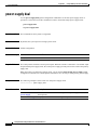
alarm facility power-supply
A-3
alarm facility temperature
alarm profile (interface configuration)
fcs-threshold
show alarm profile
show alarm settings
A-14
A-16
show facility-alarm status
show fcs-threshold
debug autoqos
debug pm
A-19
A-20
B-1
B-2
B-4
debug etherchannel
debug pagp
A-18
A-21
Debug Commands
debug dot1x
A-11
A-12
show facility-alarm relay
B
A-8
A-10
show alarm description port
test relay
A-6
A-9
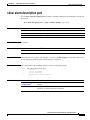
power-supply dual
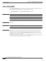
show env
A-1
A-4
alarm profile (global configuration)
APPENDIX
2-357
B-5
B-6
B-7
debug spanning-tree
B-9
debug spanning-tree backbonefast
debug spanning-tree bpdu
B-11
B-12
Catalyst 2950 and Catalyst 2955 Switch Command Reference
78-15304-01
ix
Contents
debug spanning-tree bpdu-opt
debug spanning-tree mstp
debug spanning-tree switch
B-13
B-14
B-16
debug spanning-tree uplinkfast
debug sw-vlan
B-19
debug sw-vlan ifs
B-21
debug sw-vlan notification
debug sw-vlan vtp
debug udld
B-18
B-22
B-23
B-25
INDEX
Catalyst 2950 and Catalyst 2955 Switch Command Reference
x
78-15304-01
Preface
Audience
This guide is for the networking professional using the Cisco IOS command-line interface (CLI) to
manage the Catalyst 2950 and Catalyst 2955 switches, hereafter referred to as the switch. Before using
this guide, you should have experience working with the Cisco IOS and be familiar with the concepts
and terminology of Ethernet and local area networking.
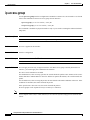
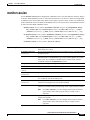
Purpose
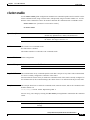
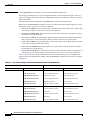
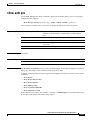
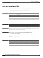
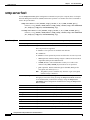
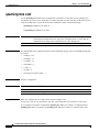
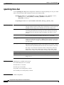
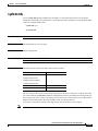
The Catalyst 2950 switch is supported by either the standard software image (SI) or the enhanced
software image (EI). The Catalyst 2955 switch uses only the EI. The enhanced software image provides
a richer set of features, including access control lists (ACLs), enhanced quality of service (QoS) features,
extended-range VLANs, the IEEE 802.1W Rapid Spanning Tree Protocol (RSTP), the IEEE 802.1S Multiple
Spanning Tree Protocol (MSTP), and and Remote Switched Port Analyzer (RSPAN).
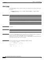
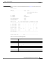
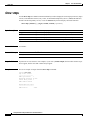
The software supports the switches listed in the release notes and in this table:
Switch
Software
Image
Catalyst 2950-12
SI
Catalyst 2950-24
SI
Catalyst 2950C-24
EI
Catalyst 2950G-12-EI
EI
Catalyst 2950G-24-EI
EI
Catalyst 2950G-24-EI-DC
EI
Catalyst 2950G-48-EI
EI
Catalyst 2950SX-24
SI
Catalyst 2950T-24
EI
Catalyst 2955C-12
EI
Catalyst 2955S-12
EI
Catalyst 2955T-12
EI
Catalyst 2950 and Catalyst 2955 Switch Command Reference
78-15304-01
xi
Preface
Organization
Note
This software release does not support the Catalyst 2950 LRE switches. For information about these
switches, refer to the Catalyst 2950 LRE switch release notes.
This guide provides the information you need about the CLI commands that have been created or
changed for use with the Catalyst 2950 family of switches. For information about the standard IOS
Release 12.1 commands, refer to the IOS documentation set available from the Cisco.com home page by
selecting Service and Support > Technical Documents. On the Cisco Product Documentation home
page, select Release 12.1 from the Cisco IOS Software drop-down list.
This guide does not provide procedures for configuring your switch. For detailed configuration
procedures, refer to the Catalyst 2950 and Catalyst 2955 Switch Software Configuration Guide for this
release.
This guide does not describe system messages you might encounter. For more information, refer to the
Catalyst 2950 and Catalyst 2955 Switch System Message Guide for this release.
Organization
This guide is organized into these chapters:
Chapter 1, “Using the Command-Line Interface,” describes how to access the command modes and use
the switch CLI to configure software features. It also lists the commands that have the same function but
different syntax in software releases earlier than Release 12.1(6)EA2 and in Release 12.1(6)EA2 or later.
Chapter 2, “Cisco IOS Commands,” describes in alphabetical order the IOS commands that you use to
configure and monitor your switch.
Appendix A, “Catalyst 2955-Specific Alarm Commands,” describes the IOS commands that you use to
set alarms related to temperature, power supply conditions, and the status of the Ethernet ports.
Appendix B, “Debug Commands,” describes the debug privileged EXEC commands. Debug commands
are helpful in diagnosing and resolving internetworking problems.
Conventions
This guide uses these conventions to convey instructions and information:
Command descriptions use these conventions:
•
Commands and keywords are in boldface text.
•
Arguments for which you supply values are in italic.
•
Square brackets ([ ]) mean optional elements.
•
Braces ({ }) group required choices, and vertical bars ( | ) separate the alternative elements.
•
Braces and vertical bars within square brackets ([{ | }]) mean a required choice within an optional
element.
Catalyst 2950 and Catalyst 2955 Switch Command Reference
xii
78-15304-01
Preface
Related Publications
Interactive examples use these conventions:
•
Terminal sessions and system displays are in screen font.
•
Information you enter is in boldface
•
Nonprinting characters, such as passwords or tabs, are in angle brackets (< >).
screen
font.
Notes, cautions, and tips use these conventions and symbols:
Note
Caution
Timesaver
Means reader take note. Notes contain helpful suggestions or references to materials not contained in
this manual.
Means reader be careful. In this situation, you might do something that could result in equipment
damage or loss of data.
Means the following will help you solve a problem. The tips information might not be troubleshooting
or even an action, but could be useful information.
Related Publications
These documents provide complete information about the switch and are available from this URL:
http://www.cisco.com/univercd/cc/td/doc/product/lan/cat2950/index.htm
You can order printed copies of documents with a DOC-xxxxxx= number from the Cisco.com sites and
from the telephone numbers listed in the “Obtaining Documentation” section on page xiv.
•
Note
Release Notes for the Catalyst 2955 Switch, (not orderable but is available on Cisco.com)
Switch requirements and procedures for initial configurations and software upgrades tend to change and
therefore appear only in the release notes. Before installing, configuring, or upgrading the switch, refer
to the release notes on Cisco.com for the latest information.
•
Catalyst 2950 and Catalyst 2955 Switch Software Configuration Guide (order number
DOC-7815303=)
•
Catalyst 2950 and Catalyst 2955 Switch Command Reference (order number DOC-7815304=)
•
Catalyst 2955 Desktop Switch System Message Guide (order number DOC-7815306=)
•
Catalyst 2955 Hardware Installation Guide (order number DOC-7814944=)
•
Catalyst GigaStack Gigabit Interface Converter Hardware Installation Guide
(order number DOC-786460=)
•
Cluster Management Suite (CMS) online help (available only from the switch CMS software)
•
CWDM Passive Optical System Installation Note (not orderable but is available on Cisco.com)
•
1000BASE-T Gigabit Interface Converter Installation Notes (not orderable but is available on
Cisco.com)
Catalyst 2950 and Catalyst 2955 Switch Command Reference
78-15304-01
xiii
Preface
Obtaining Documentation
Note
For information about the Catalyst 2950 LRE switches, refer to these documents:
Catalyst 2950 Desktop Switch Software Configuration Guide, Cisco IOS Release 12.1(11)EA1 and
Release 12.1(11)YJ (order number DOC-7814982=)
Catalyst 2950 Desktop Switch Command Reference, Cisco IOS Release 12.1(11)EA1 and
Release 12.1(11)YJ (order number DOC-7814984=)
Catalyst 2950 Desktop Switch System Message Guide, Cisco IOS Release 12.1(11)EA1 and
Release 12.1(11)YJ (order number DOC-7814981=)
Release Notes for the Catalyst 2950 LRE Switch, Cisco IOS Release 12.1(11)YJ (not orderable but is
available on Cisco.com)
Obtaining Documentation
The following sections provide sources for obtaining documentation from Cisco Systems.
World Wide Web
You can access the most current Cisco documentation on the World Wide Web at the following sites:
•
http://www.cisco.com
•
http://www-china.cisco.com
•
http://www-europe.cisco.com
Documentation CD-ROM
Cisco documentation and additional literature are available in a CD-ROM package. The Documentation
CD-ROM is updated monthly and may be more current than printed documentation. The CD-ROM
package is available as a single unit or as an annual subscription.
Ordering Documentation
Cisco documentation is available in the following ways:
•
Registered Cisco Direct Customers can order Cisco Product documentation from the Networking
Products MarketPlace:
http://www.cisco.com/cgi-bin/order/order_root.pl
•
Registered Cisco.com users can order the Documentation CD-ROM through the online Subscription
Store:
http://www.cisco.com/go/subscription
Catalyst 2950 and Catalyst 2955 Switch Command Reference
xiv
78-15304-01
Preface
Obtaining Technical Assistance
•
Nonregistered Cisco.com users can order documentation through a local account representative by
calling Cisco corporate headquarters (California, USA) at 408 526-7208 or, in North America, by
calling 800 553-NETS(6387).
Documentation Feedback
If you are reading Cisco product documentation on the World Wide Web, you can submit technical
comments electronically. Click Feedback in the toolbar and select Documentation. After you complete
the form, click Submit to send it to Cisco.
You can e-mail your comments to [email protected].
To submit your comments by mail, for your convenience many documents contain a response card
behind the front cover. Otherwise, you can mail your comments to the following address:
Cisco Systems, Inc.
Document Resource Connection
170 West Tasman Drive
San Jose, CA 95134-9883
We appreciate your comments.
Obtaining Technical Assistance
Cisco provides Cisco.com as a starting point for all technical assistance. Customers and partners can
obtain documentation, troubleshooting tips, and sample configurations from online tools. For Cisco.com
registered users, additional troubleshooting tools are available from the TAC website.
Cisco.com
Cisco.com is the foundation of a suite of interactive, networked services that provides immediate, open
access to Cisco information and resources at anytime, from anywhere in the world. This highly
integrated Internet application is a powerful, easy-to-use tool for doing business with Cisco.
Cisco.com provides a broad range of features and services to help customers and partners streamline
business processes and improve productivity. Through Cisco.com, you can find information about Cisco
and our networking solutions, services, and programs. In addition, you can resolve technical issues with
online technical support, download and test software packages, and order Cisco learning materials and
merchandise. Valuable online skill assessment, training, and certification programs are also available.
Customers and partners can self-register on Cisco.com to obtain additional personalized information and
services. Registered users can order products, check on the status of an order, access technical support,
and view benefits specific to their relationships with Cisco.
To access Cisco.com, go to the following website:
http://www.cisco.com
Technical Assistance Center
The Cisco TAC website is available to all customers who need technical assistance with a Cisco product
or technology that is under warranty or covered by a maintenance contract.
Catalyst 2950 and Catalyst 2955 Switch Command Reference
78-15304-01
xv
Preface
Obtaining Technical Assistance
Contacting TAC by Using the Cisco TAC Website
If you have a priority level 3 (P3) or priority level 4 (P4) problem, contact TAC by going to the TAC
website:
http://www.cisco.com/tac
P3 and P4 level problems are defined as follows:
•
P3—Your network performance is degraded. Network functionality is noticeably impaired, but most
business operations continue.
•
P4—You need information or assistance on Cisco product capabilities, product installation, or basic
product configuration.
In each of the above cases, use the Cisco TAC website to quickly find answers to your questions.
To register for Cisco.com, go to the following website:
http://www.cisco.com/register/
If you cannot resolve your technical issue by using the TAC online resources, Cisco.com registered users
can open a case online by using the TAC Case Open tool at the following website:
http://www.cisco.com/tac/caseopen
Contacting TAC by Telephone
If you have a priority level 1(P1) or priority level 2 (P2) problem, contact TAC by telephone and
immediately open a case. To obtain a directory of toll-free numbers for your country, go to the following
website:
http://www.cisco.com/warp/public/687/Directory/DirTAC.shtml
P1 and P2 level problems are defined as follows:
•
P1—Your production network is down, causing a critical impact to business operations if service is
not restored quickly. No workaround is available.
•
P2—Your production network is severely degraded, affecting significant aspects of your business
operations. No workaround is available.
Catalyst 2950 and Catalyst 2955 Switch Command Reference
xvi
78-15304-01
C H A P T E R
1
Using the Command-Line Interface
The Catalyst 2950 and Catalyst 2955 switches are supported by Cisco IOS software. This chapter
describes how to use the switch command-line interface (CLI) to configure the software features.
For a complete description of the commands that support these features, see Chapter 2, “Cisco IOS
Commands.” For Catalyst 2955-specific commands for setting alarms, refer to Appendix A, “Catalyst
2955-Specific Alarm Commands.” For more information on Cisco IOS Release 12.1, refer to the Cisco
IOS Release 12.1 Command Summary.
For task-oriented configuration steps, refer to the software configuration guide for this release.
The switches are preconfigured and begin forwarding packets as soon as they are attached to compatible
devices.
By default, all ports belong to virtual LAN (VLAN) 1. Access to the switch itself is also through
VLAN 1, which is the default management VLAN. The management VLAN is configurable. You
manage the switch by using Telnet, Secure Shell (SSH) Protocol, web-based management, and Simple
Network Management Protocol (SNMP) through devices connected to ports assigned to the management
VLAN.
Type of Memory
The switch Flash memory stores the Cisco IOS software image, the startup and private configuration
files, and helper files.
Platforms
This IOS release runs on a variety of switches. For a complete list, refer to the release notes for this
software release.
Note
This software release does not support the Catalyst 2950 LRE switches. For information about these
switches, refer to the Catalyst 2950 LRE switch release notes.
Catalyst 2950 and Catalyst 2955 Switch Command Reference
78-15304-01
1-1
Chapter 1
Using the Command-Line Interface
CLI Command Modes
CLI Command Modes
This section describes the CLI command mode structure. Command modes support specific Cisco IOS
commands. For example, the interface type_number command works only when entered in global
configuration mode. These are the main command modes:
•
User EXEC
•
Privileged EXEC
•
Global configuration
•
Interface configuration
•
Config-vlan
•
VLAN configuration
•
Line configuration
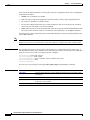
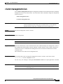
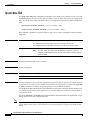
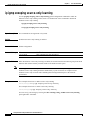
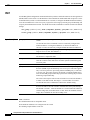
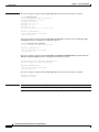
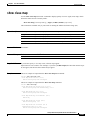
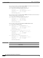
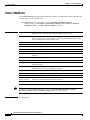
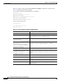
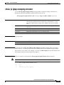
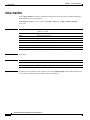
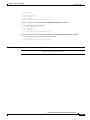
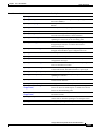
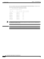
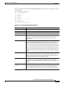
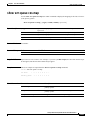
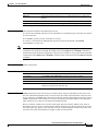
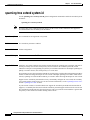
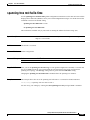
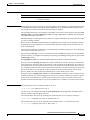
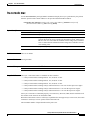
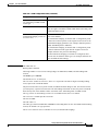
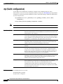
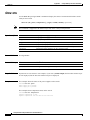
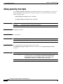
Table 1-1 lists the command modes, how to access each mode, the prompt you see in that mode, and how
to exit that mode. The prompts listed assume the default name Switch.
Table 1-1
Command Modes Summary
Command Mode
Access Method
Prompt
Exit or Access Next Mode
User EXEC
This is the first level of access.
Switch>
Enter the logout command.
(For the switch) Change terminal
settings, perform basic tasks, and
list system information.
Privileged EXEC
From user EXEC mode, enter the
enable command.
To enter privileged EXEC mode, enter
the enable command.
Switch#
To exit to user EXEC mode, enter the
disable command.
To enter global configuration mode,
enter the configure command.
Global
configuration
From privileged EXEC mode,
enter the configure command.
Switch(config)#
To exit to privileged EXEC mode,
enter the exit or end command, or
press Ctrl-Z.
To enter interface configuration mode,
enter the interface command.
Interface
configuration
From global configuration mode,
specify an interface by entering
the interface command.
Switch(config-if)#
To exit to privileged EXEC mode,
enter the end command, or press
Ctrl-Z.
To exit to global configuration mode,
enter the exit command.
To enter subinterface configuration
mode, specify a subinterface with the
interface command.
Config-vlan
In global configuration mode,
enter the vlan vlan-id command.
Switch(config-vlan)#
To exit to global configuration mode,
enter the exit command.
To return to privileged EXEC mode,
enter the end command, or press
Ctrl-Z.
Catalyst 2950 and Catalyst 2955 Switch Command Reference
1-2
78-15304-01
Chapter 1
Using the Command-Line Interface
CLI Command Modes
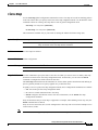
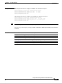
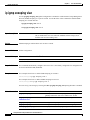
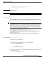
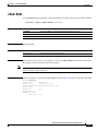
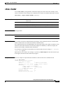
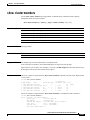
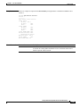
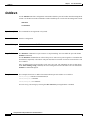
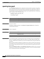
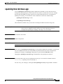
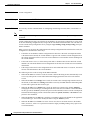
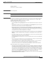
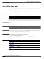
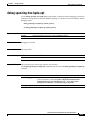
Table 1-1
Command Modes Summary (continued)
Command Mode
Access Method
Prompt
Exit or Access Next Mode
VLAN
configuration
From privileged EXEC mode,
enter the vlan database
command.
Switch(vlan)#
To exit to privileged EXEC mode,
enter the exit command.
Line configuration
From global configuration mode,
specify a line by entering the line
command.
Switch(config-line)#
To exit to global configuration mode,
enter the exit command.
To return to privileged EXEC mode,
enter the end command, or press
Ctrl-Z.
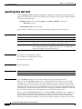
User EXEC Mode
After you access the device, you are automatically in user EXEC command mode. The EXEC commands
available at the user level are a subset of those available at the privileged level. In general, use the user
EXEC commands to change terminal settings temporarily, to perform basic tests, and to list system
information.
The supported commands can vary depending on the version of IOS software in use. To view a
comprehensive list of commands, enter a question mark (?) at the prompt.
Switch> ?
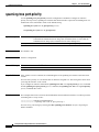
Privileged EXEC Mode
Because many of the privileged commands configure operating parameters, privileged access should be
password-protected to prevent unauthorized use. The privileged command set includes those commands
contained in user EXEC mode, as well as the configure command through which you access the
remaining command modes.
If your system administrator has set a password, you are prompted to enter it before being granted access
to privileged EXEC mode. The password does not appear on the screen and is case sensitive.
The privileged EXEC mode prompt is the device name followed by the pound sign ( #).
Switch#
Enter the enable command to access privileged EXEC mode:
Switch> enable
Switch#
The supported commands can vary depending on the version of IOS software in use. To view a
comprehensive list of commands, enter a question mark (?) at the prompt.
Switch# ?
To return to user EXEC mode, enter the disable command.
Catalyst 2950 and Catalyst 2955 Switch Command Reference
78-15304-01
1-3
Chapter 1
Using the Command-Line Interface
CLI Command Modes
Global Configuration Mode
Global configuration commands apply to features that affect the device as a whole. Use the configure
privileged EXEC command to enter global configuration mode. The default is to enter commands from
the management console.
When you enter the configure command, a message prompts you for the source of the configuration
commands:
Switch# configure
Configuring from terminal, memory, or network [terminal]?
You can specify either the terminal or nonvolatile RAM (NVRAM) as the source of configuration
commands.
This example shows you how to access global configuration mode:
Switch# configure terminal
Enter configuration commands, one per line.
End with CNTL/Z.
The supported commands can vary depending on the version of IOS software in use. To view a
comprehensive list of commands, enter a question mark (?) at the prompt.
Switch(config)# ?
To exit global configuration command mode and to return to privileged EXEC mode, enter the end or
exit command, or press Ctrl-Z.
Interface Configuration Mode
Interface configuration commands modify the operation of the interface. Interface configuration
commands always follow a global configuration command, which defines the interface type.
Use the interface type_number.subif command to access interface configuration mode. The new prompt
shows interface configuration mode.
Switch(config-if)#
The supported commands can vary depending on the version of IOS software in use. To view a
comprehensive list of commands, enter a question mark (?) at the prompt.
Switch(config-if)# ?
To exit interface configuration mode and to return to global configuration mode, enter the exit command.
To exit interface configuration mode and to return to privileged EXEC mode, enter the end command,
or press Ctrl-Z.
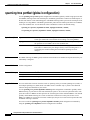
config-vlan Mode
Use this mode to configure normal-range VLANs (VLAN IDs 1 to 1005) or, when VTP mode is
transparent, to configure extended-range VLANs (VLAN IDs 1006 to 4094) when the enhanced software
image is installed. When VTP mode is transparent, the VLAN and VTP configuration is saved in the
running configuration file, and you can save it to the switch startup configuration file by using the copy
running-config startup-config privileged EXEC command. The configurations of VLAN IDs 1 to 1005
are saved in the VLAN database if VTP is in transparent or server mode. The extended-range VLAN
configurations are not saved in the VLAN database.
Catalyst 2950 and Catalyst 2955 Switch Command Reference
1-4
78-15304-01
Chapter 1
Using the Command-Line Interface
CLI Command Modes
Enter the vlan vlan-id global configuration command to access config-vlan mode:
Switch(config)# vlan 2000
Switch(config-vlan)#
The supported keywords can vary but are similar to the commands available in VLAN configuration
mode. To view a comprehensive list of commands, enter a question mark (?) at the prompt.
Switch(config-vlan)# ?
For extended-range VLANs, all characteristics except MTU size must remain at the default setting.
To return to global configuration mode, enter exit; to return to privileged EXEC mode, enter end. All
commands except shutdown take effect when you exit config-vlan mode.
VLAN Configuration Mode
You can use the VLAN configuration commands to create or modify VLAN parameters for VLANs 1 to
1005. Enter the vlan database privileged EXEC command to access VLAN configuration mode:
Switch# vlan database
Switch(vlan)#
The supported commands can vary depending on the version of IOS software in use. To view a
comprehensive list of commands, enter a question mark (?) at the prompt.
Switch(vlan)# ?
To return to privileged EXEC mode, enter the abort command to abandon the proposed database.
Otherwise, enter exit to implement the proposed new VLAN database and to return to privileged EXEC
mode.
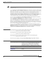
Line Configuration Mode
Line configuration commands modify the operation of a terminal line. Line configuration commands
always follow a line command, which defines a line number. Use these commands to change terminal
parameter settings line-by-line or for a range of lines.
Use the line vty line_number [ending_line_number] command to enter line configuration mode. The
new prompt indicates line configuration mode.
This example shows how to enter line configuration mode for virtual terminal line 7:
Switch(config)# line vty 0 7
The supported commands can vary depending on the version of IOS software in use. To view a
comprehensive list of commands, enter a question mark (?) at the prompt.
Switch(config-line)# ?
To exit line configuration mode and to return to global configuration mode, use the exit command.
To exit line configuration mode and to return to privileged EXEC mode, enter the end command, or press
Ctrl-Z.
Catalyst 2950 and Catalyst 2955 Switch Command Reference
78-15304-01
1-5
Chapter 1
Using the Command-Line Interface
Command Summary
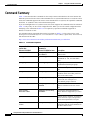
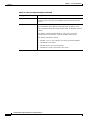
Command Summary
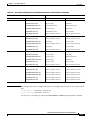
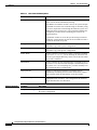
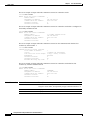
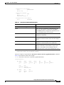
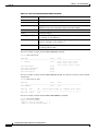
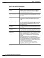
Table 1-2 lists and describes commands for the Catalyst 2950 switch that have the same function but
different syntax in software releases earlier than Release 12.1(6)EA2 and in Release 12.1(6)EA2 or later.
It lists the commands supported in releases earlier than Release 12.1(6)EA2, the equivalent commands
in Release 12.1(6)EA2 or later, and command descriptions.
If you are running Release 12.1(6)EA2 or later, the switch supports the commands in the left column of
Table 1-2 only if they are in a saved configuration file. When you save the switch configuration after
modifying it, the commands in Table 1-2 are replaced by equivalent commands supported in
Release 12.1(6)EA2 or later.
For information about commands listed in the left column of Table 1-2, refer to the Catalyst 2950
Desktop Switch Command Reference, Cisco IOS Release 12.0(5.2)WC(1) (April 2001). You can access
this document at this URL:
http://www.cisco.com/univercd/cc/td/doc/product/lan/cat2950/2950_wc/index.htm.
Table 1-2
Command Comparison
Command in IOS releases
earlier than
Release 12.1(6)EA2
Command in
Release 12.1(6)EA2 or later
Description
mac-address-table secure
switchport port-security
mac-address
Adds secure addresses to the MAC
address table.
no negotiation auto
speed nonegotiate
Disables autonegotiation on
1000BASE-X, -LX, and -ZX GBIC1
ports.
port group
channel-group
Assigns a port to a Fast EtherChannel or
Gigabit EtherChannel port group.
port monitor
monitor session
Enables SPAN2 port monitoring on a
port.
port protected
switchport protected
Isolates Layer 2 unicast, multicast, and
broadcast traffic from other protected
ports on the same switch.
port security
switchport port-security
Enables port security on a port and
restricts the use of the port to a
user-defined group of stations.
port security action
switchport port-security
violation
Specifies the action to take when an
address violation occurs on a secure
port.
port security
max-mac-count
switchport port-security
maximum
Specifies the maximum number of
secure addresses supported by a secure
port.
port storm-control
storm-control
Enables unicast, multicast, or broadcast
storm control on a port, and specifies
storm-control parameters on a port.
show mac-address-table
secure
show port-security
Displays the port security settings for
an interface and the secure addresses in
the MAC address table.
Catalyst 2950 and Catalyst 2955 Switch Command Reference
1-6
78-15304-01
Chapter 1
Using the Command-Line Interface
Command Summary
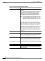
Table 1-2
Command Comparison (continued)
Command in IOS releases
earlier than
Release 12.1(6)EA2
Command in
Release 12.1(6)EA2 or later
show port group
show etherchannel
Displays EtherChannel information for
a channel.
show port monitor
show monitor
Displays SPAN session information.
show port protected
show interfaces switchport
Displays the port protection settings of
a port.
show port security
show port-security
Displays the port security settings
defined for a port.
show port storm-control
show storm-control
Displays the packet-storm control
information.
spanning-tree rootguard
spanning-tree guard
Enables the root guard feature for all
VLANs associated with a port.
switchport priority
mls qos cos
Defines the default CoS3 value of a port.
switchport priority
override
mls qos cos override
Assigns the default CoS value to all
incoming packets on a port.
Description
1. GBIC = Gigabit Interface Converter
2. SPAN = Switched Port Analyzer
3. CoS = class of service
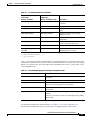
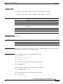
Table 1-3 lists and describes the commands that are not supported in Release 12.1(6)EA2 or later. These
commands are supported only in software releases earlier than Release 12.1(6)EA2. If you are running
Release 12.1(6)EA2 or later, the switch supports the commands listed in Table 1-3 only if they are in a
saved configuration file.
Table 1-3
Commands Not Supported in Release 12.1(6)EA2 or Later
Command
Description
clear ip address
Deletes an IP address for a switch without disabling the IP
processing.
clear mac-address-table static
Deletes static entries from the MAC address table.
management
Shuts down the current management VLAN interface and
enables the new management VLAN interface.
show mac-address-table self
Displays the addresses added by the switch itself to the MAC
address table.
spanning-tree protocol
Specifies the STP 1 to be used for specified spanning-tree
instances.
In Release 12.1(6)EA2 or later, the switch supports only IEEE
Ethernet STP.
1. STP = Spanning Tree Protocol
For detailed command syntax and descriptions, see Chapter 2, “Cisco IOS Commands.” For
task-oriented configuration steps, refer to the software configuration guide for this release.
Catalyst 2950 and Catalyst 2955 Switch Command Reference
78-15304-01
1-7
Chapter 1
Using the Command-Line Interface
Command Summary
Catalyst 2950 and Catalyst 2955 Switch Command Reference
1-8
78-15304-01
C H A P T E R
2
Cisco IOS Commands
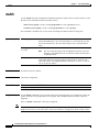
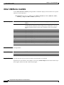
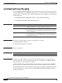
aaa authentication dot1x
Use the aaa authentication dot1x global configuration command to specify one or more authentication,
authorization, and accounting (AAA) methods for use on interfaces running IEEE 802.1X. Use the no
form of this command to disable authentication.
aaa authentication dot1x {default} method1 [method2...]
no aaa authentication dot1x {default} method1 [method2...]
Syntax Description
default
Use the listed authentication methods that follow this argument as the default
list of methods when a user logs in.
method1
[method2...]
At least one of these keywords:
•
enable—Use the enable password for authentication.
•
group radius—Use the list of all Remote Authentication Dial-In User
Service (RADIUS) servers for authentication.
•
line—Use the line password for authentication.
•
local—Use the local username database for authentication.
•
local-case—Use the case-sensitive local username database for
authentication.
•
none—Use no authentication. The client is automatically authenticated by
the switch without using the information supplied by the client.
Defaults
No authentication is performed.
Command Modes
Global configuration
Command History
Release
Modification
12.1(6)EA2
This command was first introduced.
Catalyst 2950 and Catalyst 2955 Switch Command Reference
78-15304-01
2-1
Chapter 2
Cisco IOS Commands
aaa authentication dot1x
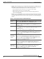
Usage Guidelines
The method argument identifies the list of methods that the authentication algorithm tries in the given
sequence to validate the password provided by the client. The only method that is truly
802.1X-compliant is the group radius method, in which the client data is validated against a RADIUS
authentication server. The remaining methods enable AAA to authenticate the client by using locally
configured data. For example, the local and local-case methods use the username and password that are
saved in the IOS configuration file. The enable and line methods use the enable and line passwords for
authentication.
If you specify group radius, you must configure the RADIUS server by entering the radius-server host
global configuration command.
If you are not using a RADIUS server, you can use the local or local-case methods, which access the
local username database to perform authentication. By specifying the enable or line methods, you can
supply the clients with a password to provide access to the switch.
Use the show running-config privileged EXEC command to display the configured lists of
authentication methods.
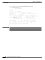
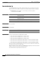
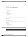
Examples
This example shows how to enable AAA and how to create an authentication list for 802.1X. This
authentication first tries to contact a RADIUS server. If this action returns an error, the user is allowed
access with no authentication.
Switch(config)# aaa new model
Switch(config)# aaa authentication dot1x default group radius none
You can verify your settings by entering the show running-config privileged EXEC command.
Related Commands
Command
Description
aaa new-model
Enables the AAA access control model. For syntax information, refer to
Cisco IOS Security Command Reference for Release 12.1 >
Authentication, Authorization, and Accounting > Authentication
Commands.
show running-config
Displays the configuration information running on the switch. For syntax
information, select Cisco IOS Configuration Fundamentals Command
Reference for Release 12.1 > Cisco IOS File Management Commands >
Configuration File Commands.
Catalyst 2950 and Catalyst 2955 Switch Command Reference
2-2
78-15304-01
Chapter 2
Cisco IOS Commands
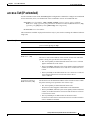
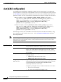
access-list (IP extended)
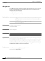
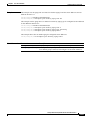
access-list (IP extended)
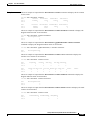
Use the extended version of the access-list global configuration command to configure an extended IP
access control list (ACL). Use the no form of this command to remove an extended IP ACL.
access-list access-list-number {deny | permit | remark} protocol {source source-wildcard |
host source | any} [operator port] {destination destination-wildcard | host destination | any}
[operator port] [dscp dscp-value] [time-range time-range-name]
no access-list access-list-number
This command is available on physical interfaces only if your switch is running the enhanced software
image (EI).
Syntax Description
access-list-number
Number of an ACL, from 100 to 199 or from 2000 to 2699.
protocol
Name of an IP protocol.
protocol can be ip, tcp, or udp.
deny
Deny access if conditions are matched.
permit
Permit access if conditions are matched.
remark
ACL entry comment up to 100 characters.
source source-wildcard |
host source | any
Define a source IP address and wildcard.
destination
destination-wildcard |
host destination | any
The source is the source address of the network or host from which the
packet is being sent, specified in one of these ways:
•
The 32-bit quantity in dotted-decimal format. The source-wildcard
applies wildcard bits to the source.
•
The keyword host, followed by the 32-bit quantity in dotted-decimal
format, as an abbreviation for source and source-wildcard of source
0.0.0.0.
•
The keyword any as an abbreviation for source and source-wildcard
of 0.0.0.0 255.255.255.255. You do not need to enter a
source-wildcard.
Define a destination IP address and wildcard.
The destination is the destination address of the network or host to which
the packet is being sent, specified in one of these ways:
•
The 32-bit quantity in dotted-decimal format. The
destination-wildcard applies wildcard bits to the destination.
•
The keyword host, followed by the 32-bit quantity in dotted-decimal
format, as an abbreviation for destination and destination-wildcard
of destination 0.0.0.0.
•
The keyword any as an abbreviation for destination and
destination-wildcard of 0.0.0.0 255.255.255.255. You do not need to
enter a destination-wildcard.
Catalyst 2950 and Catalyst 2955 Switch Command Reference
78-15304-01
2-3
Chapter 2
Cisco IOS Commands
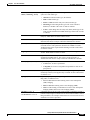
access-list (IP extended)
operator port
(Optional) Define a source or destination port.
The operator can be only eq (equal).
If operator is after the source IP address and wildcard, conditions match
when the source port matches the defined port.
If operator is after the destination IP address and wildcard, conditions
match when the destination port matches the defined port.
The port is a decimal number or name of a Transmission Control Protocol
(TCP) or User Datagram Protocol (UDP) port. The number can be from
0 to 65535.
Use TCP port names only for TCP traffic.
Use UDP port names only for UDP traffic.
dscp dscp-value
(Optional) Define a Differentiated Services Code Point (DSCP) value to
classify traffic.
For the dscp-value, enter any of the 13 supported DSCP values (0, 8, 10,
16, 18, 24, 26, 32, 34, 40, 46, 48, and 56), or use the question mark (?) to
see a list of available values.
time-range
time-range-name
(Optional) For the time-range keyword, enter a meaningful name to
identify the time range. For a more detailed explanation of this keyword,
refer to the software configuration guide.
Defaults
The default extended ACL is always terminated by an implicit deny statement for all packets.
Command Modes
Global configuration
Command History
Release
Modification
12.1(6)EA2
This command was first introduced.
Usage Guidelines
Plan your access conditions carefully. The ACL is always terminated by an implicit deny statement for
all packets.
You can use ACLs to control virtual terminal line access by controlling the transmission of packets on
an interface.
Extended ACLs support only the TCP and UDP protocols.
Use the show ip access-lists command to display the contents of IP ACLs.
Use the show access-lists command to display the contents of all ACLs.
Note
For more information about configuring IP ACLs, refer to the “Configuring Network Security with
ACLs” chapter in the Catalyst 2950 and Catalyst 2955 Switch Software Configuration Guide for this
release.
Catalyst 2950 and Catalyst 2955 Switch Command Reference
2-4
78-15304-01
Chapter 2
Cisco IOS Commands
access-list (IP extended)
Examples
This example shows how to configure an extended IP ACL that allows only TCP traffic to the destination
IP address 128.88.1.2 with a TCP port number of 25 and how to apply it to an interface:
Switch(config)# access-list 102 permit tcp any host 128.88.1.2 eq 25
Switch(config)# interface fastethernet0/8
Switch(config-if)# ip access-group 102 in
This is an example of an extended ACL that allows TCP traffic only from two specified networks. The
wildcard bits apply to the host portions of the network addresses. Any host with a source address that
does not match the ACL statements is denied.
access-list 104 permit tcp 192.5.0.0 0.0.255.255 any
access-list 104 permit tcp 128.88.0.0 0.0.255.255 any
Note
In these examples, all other IP access is implicitly denied.
You can verify your settings by entering the show ip access-lists or show access-lists privileged EXEC
command.
Related Commands
Command
Description
access-list (IP standard)
Configures a standard IP ACL.
ip access-group
Controls access to an interface.
show access-lists
Displays ACLs configured on the switch.
show ip access-lists
Displays IP ACLs configured on the switch.
Catalyst 2950 and Catalyst 2955 Switch Command Reference
78-15304-01
2-5
Chapter 2
Cisco IOS Commands
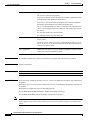
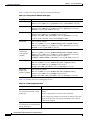
access-list (IP standard)
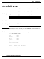
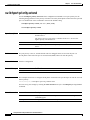
access-list (IP standard)
Use the standard version of the access-list global configuration command to configure a standard IP
access control list (ACL). Use the no form of this command to remove a standard IP ACL.
access-list access-list-number {deny | permit | remark} {source source-wildcard | host source |
any}
no access-list access-list-number
This command is available on physical interfaces only if your switch is running the enhanced software
image (EI).
Syntax Description
access-list-number
Number of an ACL, from 1 to 99 or from 1300 to 1999.
deny
Deny access if conditions are matched.
permit
Permit access if conditions are matched.
remark
ACL entry comment up to 100 characters.
source source-wildcard |
host source | any
Define a source IP address and wildcard.
The source is the source address of the network or host from which the
packet is being sent, specified in one of these ways:
•
The 32-bit quantity in dotted-decimal format. The source-wildcard
applies wildcard bits to the source.
•
The keyword host, followed by the 32-bit quantity in dotted-decimal
format, as an abbreviation for source and source-wildcard of source
0.0.0.0.
•
The keyword any as an abbreviation for source and source-wildcard
of 0.0.0.0 255.255.255.255. You do not need to enter a
source-wildcard.
Defaults
The default standard ACL is always terminated by an implicit deny statement for all packets.
Command Modes
Global configuration
Command History
Release
Modification
12.1(6)EA2
This command was first introduced.
Usage Guidelines
Plan your access conditions carefully. The ACL is always terminated by an implicit deny statement for
all packets.
You can use ACLs to control virtual terminal line access by controlling the transmission of packets on
an interface.
Catalyst 2950 and Catalyst 2955 Switch Command Reference
2-6
78-15304-01
Chapter 2
Cisco IOS Commands
access-list (IP standard)
Use the show ip access-lists command to display the contents of IP ACLs.
Use the show access-lists command to display the contents of all ACLs.
Note
Examples
For more information about configuring IP ACLs, refer to the “Configuring Network Security with
ACLs” chapter in the Catalyst 2950 and Catalyst 2955 Switch Software Configuration Guide for this
release.
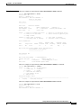
This example shows how to configure a standard IP ACL that allows only traffic from the host network
128.88.1.10 and how to apply it to an interface:
Switch(config)# access-list 12 permit host 128.88.1.10
Switch(config)# interface gigabitethernet0/1
Switch(config-if)# ip access-group 12 in
This is an example of an standard ACL that allows traffic only from three specified networks. The
wildcard bits apply to the host portions of the network addresses. Any host with a source address that
does not match the ACL statements is denied.
access-list 14 permit 192.5.34.0 0.0.0.255
access-list 14 permit 128.88.0.0 0.0.0.255
access-list 14 permit 36.1.1.0 0.0.0.255
Note
In these examples, all other IP access is implicitly denied.
You can verify your settings by entering the show ip access-lists or show access-lists privileged EXEC
command.
Related Commands
Command
Description
access-list (IP extended)
Configures an extended IP ACL.
ip access-group
Controls access to an interface.
show access-lists
Displays ACLs configured on the switch.
show ip access-lists
Displays IP ACLs configured on the switch.
Catalyst 2950 and Catalyst 2955 Switch Command Reference
78-15304-01
2-7
Chapter 2
Cisco IOS Commands
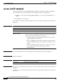
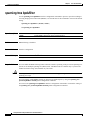
auto qos voip
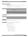
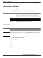
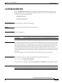
auto qos voip
Use the auto qos voip interface configuration command to configure automatic quality of service
(auto-QoS) for voice over IP (VoIP) within a QoS domain. Use the no form of this command to change
the auto-QoS configuration settings to the standard-QoS defaults.
auto qos voip {cisco-phone | trust}
no auto qos voip
This command is available only if your switch is running the enhanced software image (EI).
Syntax Description
Defaults
cisco-phone
Identify this interface as connected to a Cisco IP phone, and automatically
configure QoS for VoIP. The QoS labels of incoming packets are trusted
only when the phone is detected.
trust
Identify this interface as connected to a trusted switch or router. The QoS
labels of incoming packets are trusted.
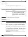
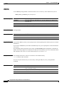
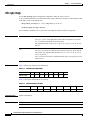
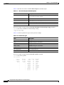
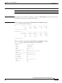
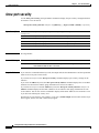
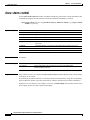
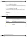
Auto-QoS is disabled on all interfaces.
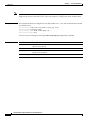
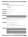
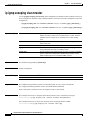
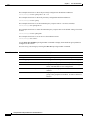
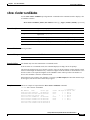
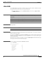
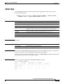
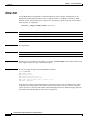
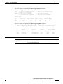
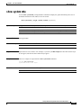
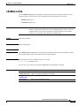
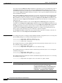
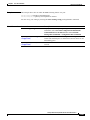
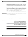
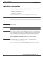
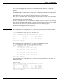
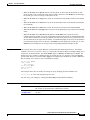
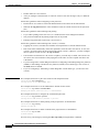
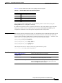
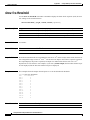
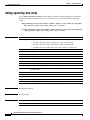
When auto-QoS is enabled, it uses the ingress packet label to categorize traffic and to configure the
egress queues as summarized in Table 2-1.
Table 2-1
Traffic Types, Ingress Packet Labels, Assigned Packet Labels, and Egress Queues
VoIP Data
Traffic Only
From Cisco IP
Phones
VoIP Control
Traffic Only
From Cisco IP
Phones
Routing Protocol STP1 BPDU2
Traffic
Traffic
All Other
Traffic
Ingress DSCP3
46
26
–
–
–
Ingress CoS
5
3
6
7
–
Assigned DSCP
46
26
48
56
0
Assigned CoS
5
3
6
7
0
CoS-to-Queue
Map
5
Egress Queue
Expedite
queue
3, 6, 7
80% WRR4
0, 1, 2, 4
20% WRR
1. STP = Spanning Tree Protocol
2. BPDU = bridge protocol data unit
3. DSCP = Differentiated Services Code Point
4. WRR = weighted round robin
Catalyst 2950 and Catalyst 2955 Switch Command Reference
2-8
78-15304-01
Chapter 2
Cisco IOS Commands
auto qos voip
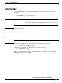
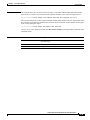
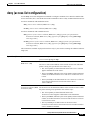
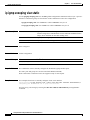
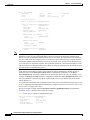
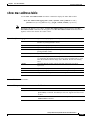
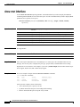
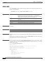
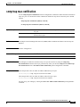
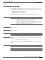
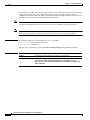
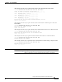
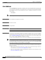
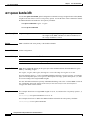
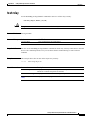
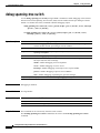
Table 2-2 lists the auto-QoS configuration for the egress queues.
Table 2-2
Auto-QoS Configuration for the Egress Queues
Egress Queue
Queue Number
CoS-to-Queue Map
Queue Weight
Expedite
4
5
–
80% WRR
3
3, 6, 7
80%
20% WRR
1
0, 1, 2, 4
20%
Command Modes
Interface configuration
Command History
Release
Modification
12.1(12c)EA1
This command was first introduced.
Usage Guidelines
Use this command to configure the QoS that is appropriate for VoIP traffic within the QoS domain. The
QoS domain includes the switch, the interior of the network, and the edge devices that can classify
incoming traffic for QoS.
Use the cisco-phone keyword on ports connected to Cisco IP phones at the edge of the network. The
switch detects the phone through the Cisco Discovery Protocol (CDP) and trusts the QoS labels in
packets received from the phone.
Use the trust keyword on ports connected to the interior of the network. Because it is assumed that traffic
has already been classified by other edge devices, the QoS labels in these packets from the interior of
the network are trusted.
When you enable the auto-QoS feature on the first interface, these automatic actions occur:
•
When you enter the auto qos voip cisco-phone interface configuration command, the trusted
boundary feature is enabled. It uses the Cisco Discovery Protocol (CDP) to detect the presence or
absence of a Cisco IP phone. When a Cisco IP phone is detected, the ingress classification on the
interface is set to trust the QoS label received in the packet. When a Cisco IP phone is absent, the
ingress classification is set to not trust the QoS label in the packet. The egress queues on the
interface are also reconfigured (see Table 2-2).
•
When you enter the auto qos voip trust interface configuration command, the ingress classification
on the interface is set to trust the QoS label received in the packet, and the egress queues on the
interface are reconfigured (see Table 2-2).
You can enable auto-QoS on static, dynamic-access, voice VLAN access, and trunk ports.
To display the QoS configuration that is automatically generated when auto-QoS is enabled, enable
debugging before you enable auto-QoS. Use the debug autoqos privileged EXEC command to enable
auto-QoS debugging.
To disable auto-QoS on an interface, use the no auto qos voip interface configuration command. When
you enter this command, the switch changes the auto-QoS settings to the standard-QoS default settings
for that interface.
To disable auto-QoS on the switch, use the no auto qos voip interface configuration command on all
interfaces on which auto-QoS is enabled. When you enter this command on the last interface on which
auto-QoS is enabled, the switch enables pass-through mode.
Catalyst 2950 and Catalyst 2955 Switch Command Reference
78-15304-01
2-9
Chapter 2
Cisco IOS Commands
auto qos voip
Examples
This example shows how to enable auto-QoS and to trust the QoS labels received in incoming packets
when the switch or router connected to Gigabit Ethernet interface 0/1 is a trusted device:
Switch(config)# interface gigabitethernet0/1
Switch(config-if)# auto qos voip trust
This example shows how to enable auto-QoS and to trust the QoS labels received in incoming packets
when the device connected to Fast Ethernet interface 0/1 is detected as a Cisco IP phone:
Switch(config)# interface fastethernet0/1
Switch(config-if)# auto qos voip cisco-phone
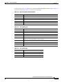
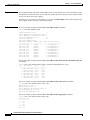
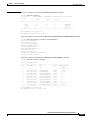
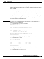
This example shows how to display the QoS configuration that is automatically generated when
auto-QoS is enabled:
Switch# debug autoqos
AutoQoS debugging is on
Switch# configure terminal
Enter configuration commands, one per line. End with CNTL/Z.
Switch(config)# interface fastethernet0/10
Switch(config-if)# auto qos voip cisco-phone
00:02:54:wrr-queue bandwidth 20 1 80 0
00:02:55:no wrr-queue cos-map
00:02:55:wrr-queue cos-map 1 0 1 2 4
00:02:56:wrr-queue cos-map 3 3 6 7
00:02:58:wrr-queue cos-map 4 5
00:02:59:mls qos map cos-dscp 0 8 16 26 32 46 48 56
00:03:00:interface FastEthernet0/10
00:03:00: mls qos trust device cisco-phone
00:03:00: mls qos trust cos
Switch(config-if)# interface fastethernet0/12
Switch(config-if)# auto qos voip trust
00:03:15:interface FastEthernet0/12
00:03:15: mls qos trust cos
Switch(config-if)#
You can verify your settings by entering the show auto qos interface interface-id privileged EXEC
command.
Related Commands
Command
Description
debug autoqos
Enable debugging of the auto-QoS feature.
mls qos map
Defines the CoS-to-DSCP map or the DSCP-to-CoS map.
mls qos trust
Configures the port trust state.
show auto qos
Displays auto-QoS information.
show mls qos maps
Displays QoS mapping information.
show mls qos interface
Displays QoS information at the interface level.
Catalyst 2950 and Catalyst 2955 Switch Command Reference
2-10
78-15304-01
Chapter 2
Cisco IOS Commands
boot private-config-file
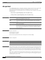
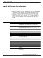
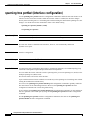
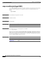
boot private-config-file
Use the boot private-config-file global configuration command to specify the filename that IOS uses to
read and write a nonvolatile copy of the private configuration. Use the no form of this command to return
to the default setting.
boot private-config-file filename
no boot private-config-file
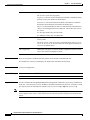
Syntax Description
filename
Defaults
The default configuration file is private-config.text.
Command Modesb
Global configuration
Command History
Release
Modification
12.1(11)EA1
This command was first introduced.
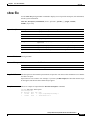
Usage Guidelines
The name of the private configuration file.
Only the IOS software can read and write a copy of the private configuration file. You cannot read, write,
delete, or display a copy of this file.
Filenames are case sensitive.
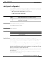
Examples
This example shows how to specify the name of the private configuration file as pconfig:
Switch(config)# boot private-config-file pconfig
Related Commands
Command
Description
show boot
Displays the settings of the boot environment variables.
Catalyst 2950 and Catalyst 2955 Switch Command Reference
78-15304-01
2-11
Chapter 2
Cisco IOS Commands
channel-group
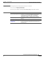
channel-group
Use the channel-group interface configuration command to assign an Ethernet interface to an
EtherChannel group. Use the no form of this command to remove an Ethernet interface from an
EtherChannel group.
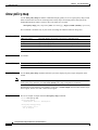
channel-group channel-group-number mode {auto [non-silent] | desirable [non-silent] | on |
active | passive}
no channel-group
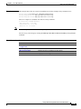
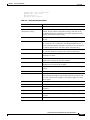
Syntax Description
channel-group-number
Specify the channel group number. The range is 1 to 6.
mode
Specify the EtherChannel Port Aggregation Protocol (PAgP) or Link
Aggregration Control Protocol (LACP). mode of the interface.
active
Unconditionally enable LACP.
Active mode places an interface into a negotiating state in which the
interface initiates negotiations with other interfaces by sending LACP
packets. A channel is formed with another port group in either the active or
passive mode. When active is enabled, silent operation is the default.
auto
Enable PAgP only if a PAgP device is detected.
Auto mode places an interface into a passive negotiating state, in which the
interface responds to PAgP packets it receives but does not initiate PAgP
packet negotiation. A channel is formed only with another port group in
desirable mode. When auto is enabled, silent operation is the default.
desirable
Unconditionally enable PAgP.
Desirable mode places an interface into a negotiating state in which the
interface initiates negotiations with other interfaces by sending PAgP
packets. A channel is formed with another port group in either the desirable
or auto mode. When desirable is enabled, silent operation is the default.
non-silent
(Optional) Used with the auto or desirable keyword when PAgP traffic is
expected from the other device.
on
Force the interface to channel without PAgP or LACP.
With the on mode, a usable EtherChannel exists only when an interface
group in the on mode is connected to another interface group in the on mode.
passive
Enable LACP only if an LACP device is detected.
Passive mode places an interface into a negotiating state in which the
interface responds to LACP packets it receives but does not initiate LACP
packet negotiation. A channel is formed only with another port group in
active mode. When passive is enabled, silent operation is the default.
Catalyst 2950 and Catalyst 2955 Switch Command Reference
2-12
78-15304-01
Chapter 2
Cisco IOS Commands
channel-group
Defaults
No channel groups are assigned.
There is no default mode.
Command Modes
Interface configuration
Command History
Release
Modification
12.1(6)EA2
This command was first introduced. It replaced the port group command.
12.1(12c)EA1
The active and passive keywords were added.
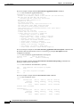
Usage Guidelines
You must specify the mode when entering this command. If the mode is not entered, an Ethernet interface
is not assigned to an EtherChannel group, and an error message appears.
You do not have to create a port-channel interface before assigning a physical interface to a channel
group. A port-channel interface is created automatically when the channel group gets its first physical
interface.
You do not have to disable the IP address that is assigned to a physical interface that is part of a channel
group, but we highly recommend that you do so.
You can create port channels by entering the interface port-channel global configuration command or
when the channel group gets its first physical interface assignment. The port channels are not created at
runtime or dynamically.
Any configuration or attribute changes you make to the port-channel interface are propagated to all
interfaces within the same channel group as the port channel (for example, configuration changes are
also propagated to the physical interfaces that are not part of the port channel, but are part of the channel
group).
With the on mode, a usable PAgP EtherChannel exists only when a port group in on mode is connected
to another port group in on mode.
If you do not specify non-silent with the auto or desirable mode, silent is assumed. The silent mode is
used when the switch is connected to a device that is not PAgP-capable and seldom, if ever, sends
packets. A example of a silent partner is a file server or a packet analyzer that is not generating traffic.
In this case, running PAgP on a physical port prevents that port from ever becoming operational;
however, it allows PAgP to operate, to attach the interface to a channel group, and to use the interface
for transmission. Both ends of the link cannot be set to silent.
Note
Caution
You cannot enable both PAgP and LACP modes on an EtherChannel group.
You should exercise care when setting the mode to on (manual configuration). All ports configured in
the on mode are bundled in the same group and are forced to have similar characteristics. If the group is
misconfigured, packet loss or Spanning Tree Protocol (STP) loops might occur.
Catalyst 2950 and Catalyst 2955 Switch Command Reference
78-15304-01
2-13
Chapter 2
Cisco IOS Commands
channel-group
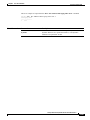
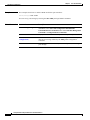
Examples
This example shows how to add an interface to the EtherChannel group specified as channel group 1:
Switch(config)# interface gigabitethernet0/1
Switch(config-if)# channel-group 1 mode on
This example shows how to set an Etherchannel into PAgP mode:
Switch(config-if)# channel-group 1 mode auto
Creating a port-channel interface Port-channel 1
This example shows how to set an Etherchannel into LACP mode:
Switch(config-if)# channel-group 1 mode passive
Creating a port-channel interface Port-channel 1
You can verify your settings by entering the show etherchannel or show running-config privileged
EXEC command.
Related Commands
Command
Description
interface port-channel Accesses or creates the port channel.
port-channel
load-balance
Sets the load distribution method among the ports in the EtherChannel.
show etherchannel
Displays EtherChannel information for a channel.
show running-config
Displays the configuration information running on the switch. For syntax
information, select Cisco IOS Configuration Fundamentals Command
Reference for Release 12.1 > Cisco IOS File Management Commands >
Configuration File Commands.
Catalyst 2950 and Catalyst 2955 Switch Command Reference
2-14
78-15304-01
Chapter 2
Cisco IOS Commands
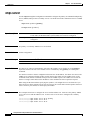
channel-protocol
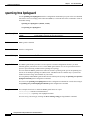
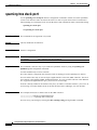
channel-protocol
Use the channel-protocol interface configuration command to configure an EtherChannel for Port
Aggregation Control Protocol (PAgP) or Link Aggregation Control Protocol (LACP). Use the no form
of this command to disable PAgP or LACP on the EtherChannel.
channel-protocol {lacp | pagp}
no channel-protocol
Syntax Description
lacp
Configure an EtherChannel with the LACP protocol.
pagp
Configure an EtherChannel with the PAgP protocol.
Defaults
No protocol is assigned to the EtherChannel.
Command Modes
Interface configuration
Command History
Release
Modification
12.1(12c)EA1
This command was first introduced.
Usage Guidelines
Note
Caution
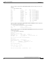
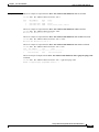
Examples
You cannot enable both PAgP and LACP modes on an EtherChannel group.
Do not enable Layer 3 addresses on the physical EtherChannel interfaces. To prevent loops, do not assign
bridge groups on the physical EtherChannel interfaces.
This example shows how to set an EtherChannel into PAgP mode:
Switch(config-if)# channel-protocol pagp
This example shows how to set an EtherChannel into LACP mode:
Switch(config-if)# channel-protocol lacp
You can verify your settings by entering the show running-config privileged EXEC command.
Catalyst 2950 and Catalyst 2955 Switch Command Reference
78-15304-01
2-15
Chapter 2
Cisco IOS Commands
channel-protocol
Related Commands
Command
Description
show lacp
Display LACP information.
show pagp
Display PAgP information.
show running-config
Displays the current operating configuration. For syntax information,
select Cisco IOS Configuration Fundamentals Command
Reference for Release 12.1 > Cisco IOS File Management
Commands > Configuration File Commands.
Catalyst 2950 and Catalyst 2955 Switch Command Reference
2-16
78-15304-01
Chapter 2
Cisco IOS Commands
class
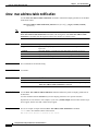
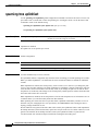
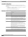
class
Use the class policy-map configuration command to define a traffic classification for the policy to act
on using the class-map name or access group. Use the no form of this command to delete an existing
class map.
class class-map-name [access-group name acl-index-or-name]
no class class-map-name
This command is available only if your switch is running the enhanced software image (EI).
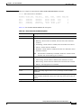
Syntax Description
class-map-name
Name of the class map.
access-group name
acl-index-or-name
(Optional) Number or name of an IP standard or extended access control list
(ACL) or name of an extended MAC ACL. For an IP standard ACL, the index
range is 1 to 99 and 1300 to 1999; for an IP extended ACL, the index range
is 100 to 199 and 2000 to 2699.
Defaults
No policy-map class maps are defined.
Command Modes
Policy-map configuration
Command History
Release
Modification
12.1(6)EA2
This command was first introduced.
Usage Guidelines
Before you use the class command, use the policy-map global configuration command to identify the
policy map and to enter policy-map configuration mode. After you specify a policy map, you can
configure a policy for new classes or modify a policy for any existing classes in that policy map. You
attach the policy map to an interface by using the service-policy interface configuration command;
however, you cannot attach one that uses an ACL classification to the egress direction.
The class name that you specify in the policy map ties the characteristics for that class to the class map
and its match criteria as configured by using the class-map global configuration command.
The class command performs the same function as the class-map global configuration command. Use
the class command when a new classification, which is not shared with any other ports, is needed. Use
the class-map command when the map is shared among many ports.
Note
In a policy map, the class named class-default is not supported. The switch does not filter traffic based
on the policy map defined by the class class-default policy-map configuration command.
Catalyst 2950 and Catalyst 2955 Switch Command Reference
78-15304-01
2-17
Chapter 2
Cisco IOS Commands
class
After entering the class command, you enter policy-map class configuration mode. These configuration
commands are available:
•
default: sets a command to its default.
•
exit: exits policy-map class configuration mode and returns to policy-map configuration mode.
•
no: returns a command to its default setting.
•
set: specifies a Differentiated Services Code Point (DSCP) value to be assigned to the classified
traffic. For more information, see the set command.
•
police: defines a policer for the classified traffic. The policer specifies the bandwidth limitations and
the action to take when the limits are exceeded. For more information, see the police command.
To return to policy-map configuration mode, use the exit command. To return to privileged EXEC mode,
use the end command.
Note
Examples
For more information about configuring ACLs, refer to the “Configuring Network Security with ACLs”
chapter in the Catalyst 2950 and Catalyst 2955 Switch Software Configuration Guide for this release.
This example shows how to create a policy map named policy1. When attached to the ingress port, it
matches all the incoming traffic defined in class1 and polices the traffic at an average rate of 1 Mbps and
bursts at 131072 bytes. Traffic exceeding the profile is dropped.
Switch(config)# policy-map policy1
Switch(config-pmap)# class class1
Switch(config-pmap-c)# police 1000000 131072 exceed-action drop
Switch(config-pmap-c)# exit
Switch(config-pmap)#
You can verify your settings by entering the show policy-map privileged EXEC command.
Related Commands
Command
Description
class-map
Creates a class map to be used for matching packets to the class whose name
you specify.
match
Defines the match criteria to classify traffic.
policy-map
Creates or modifies a policy map that can be attached to multiple interfaces
to specify a service policy.
show policy-map
Displays quality of service (QoS) policy maps.
Catalyst 2950 and Catalyst 2955 Switch Command Reference
2-18
78-15304-01
Chapter 2
Cisco IOS Commands
class-map
class-map
Use the class-map global configuration command to create a class map to be used for matching packets
to the class whose name you specify and to enter class-map configuration mode. Use the no form of this
command to delete an existing class map and to return to global configuration mode.
class-map class-map-name [match-all]
no class-map class-map-name [match-all]
This command is available only if your switch is running the enhanced software image (EI).
Syntax Description
class-map-name
Name of the class map.
match-all
(Optional) Perform a logical-AND of all matching statements under this class
map. All criteria in the class map must be matched.
Defaults
No class maps are defined.
Command Modes
Global configuration
Command History
Release
Modification
12.1(6)EA2
This command was first introduced.
Usage Guidelines
Use this command to specify the name of the class for which you want to create or modify class-map
match criteria and to enter class-map configuration mode. In this mode, you can enter one match
command to configure the match criteria for this class.
The class-map command and its subcommands are used to define packet classification and marking as
part of a globally named service policy applied on a per-interface basis.
In quality of service (QoS) class-map configuration mode, these configuration commands are available:
•
exit: exits from QoS class-map configuration mode.
•
no: removes a match statement from a class map.
•
match: configures classification criteria. For more information, see the match class-map
configuration command.
Only one match criterion per class map is supported. For example, when defining a class map, only one
match command can be entered.
Only one access control list (ACL) can be configured in a class map. The ACL can have multiple access
control entries (ACEs).
Note
The switch does not support any deny conditions in an ACL configured in a class map.
Catalyst 2950 and Catalyst 2955 Switch Command Reference
78-15304-01
2-19
Chapter 2
Cisco IOS Commands
class-map
Note
Examples
For more information about configuring ACLs, refer to the “Configuring Network Security with ACLs”
chapter in the Catalyst 2950 and Catalyst 2955 Switch Software Configuration Guide for this release.
This example shows how to configure the class map named class1. class1 has one match criteria, which
is a numbered ACL.
Switch(config)# access-list 103 permit tcp any any eq 80
Switch(config)# class-map class1
Switch(config-cmap)# match access-group 103
Switch(config-cmap)# exit
You can verify your settings by entering the show class-map privileged EXEC command.
Related Commands
Command
Description
class
Defines a traffic classification for the policy to act on by using the class-map
name or access group.
match
Defines the match criteria to classify traffic.
policy-map
Creates or modifies a policy map that can be attached to multiple interfaces to
specify a service policy.
show class-map
Displays QoS class maps.
Catalyst 2950 and Catalyst 2955 Switch Command Reference
2-20
78-15304-01
Chapter 2
Cisco IOS Commands
clear interface
clear interface
Use the clear interface privileged EXEC command to clear the hardware logic on an interface or a
VLAN.
clear interface {interface-id | vlan vlan-id}
Syntax Description
interface-id
ID of the interface.
vlan-id
VLAN ID. Valid VLAN IDs are from 1 to 4094 when the enhanced software
image (EI) is installed and 1 to 1001 when the standard software image (SI)
is installed. Do not enter leading zeros.
Defaults
No default is defined.
Command Modes
Privileged EXEC
Command History
Release
Modification
12.1(6)EA2
This command was first introduced.
Examples
This example shows how to clear the hardware logic on a Gigabit Ethernet interface:
Switch# clear interface gigabitethernet0/1
This example shows how to clear the hardware logic on a specific VLAN:
Switch# clear interface vlan 5
You can verify that the interface-reset counter for an interface is incremented by entering the show
interfaces privileged EXEC command.
Catalyst 2950 and Catalyst 2955 Switch Command Reference
78-15304-01
2-21
Chapter 2
Cisco IOS Commands
clear lacp
clear lacp
Use the clear lacp privileged EXEC command to clear Link Aggregration Control Protocol (LACP)
channel-group information.
clear lacp {channel-group-number | counters}
Syntax Description
channel-group-number
Channel group number. The range is 1 to 6.
counters
Clear traffic counters.
Defaults
This command has no default setting.
Command Modes
Privileged EXEC
Command History
Release
Modification
12.1(12c)EA1
This command was first introduced.
Examples
This example shows how to clear channel-group information for a specific group:
Switch# clear lacp 4
This example shows how to clear channel-group traffic counters:
Switch# clear lacp counters
You can verify that the information was deleted by entering the show lacp privileged EXEC command.
Related Commands
Command
Description
show lacp
Displays LACP channel-group information.
Catalyst 2950 and Catalyst 2955 Switch Command Reference
2-22
78-15304-01
Chapter 2
Cisco IOS Commands
clear mac address-table
clear mac address-table
Use the clear mac address-table privileged EXEC command to delete from the MAC address table a
specific dynamic address, all dynamic addresses on a particular interface, or all dynamic addresses on a
particular VLAN. This command also clears the MAC address notification global counters.
clear mac address-table {dynamic [address mac-addr | interface interface-id | vlan vlan-id] |
notification}
Note
Syntax Description
Beginning with Release 12.1(11)EA1, the clear mac address-table command replaces the clear
mac-address-table command (with the hyphen). The clear mac-address-table command (with the
hyphen) will become obsolete in a future release.
dynamic
Delete all dynamic MAC addresses.
dynamic address
mac-addr
(Optional) Delete the specified dynamic MAC address.
dynamic interface
interface-id
(Optional) Delete all dynamic MAC addresses on the specified physical port
or port channel.
dynamic vlan vlan-id
(Optional) Delete all dynamic MAC addresses for the specified VLAN. Valid
IDs are from 1 to 4096 when the enhanced software image (EI) is installed
and 1 to 1005 when the standard software image (SI) is installed. Do not
enter leading zeros.
notification
Clear the notifications in the history table and reset the counters.
Defaults
No default is defined.
Command Modes
Privileged EXEC
Command History
Release
Modification
12.1(6)EA2
This command was first introduced.
12.1(9)EA1
The notification keyword was added.
12.1(11)EA1
The clear mac-address-table command was replaced by the clear mac
address-table command.
Examples
This example shows how to remove a specific dynamic address from the MAC address table:
Switch# clear mac address-table dynamic address 0008.0070.0007
You can verify that the information was deleted by entering the show mac address-table privileged
EXEC command.
Catalyst 2950 and Catalyst 2955 Switch Command Reference
78-15304-01
2-23
Chapter 2
Cisco IOS Commands
clear mac address-table
Related Commands
Command
Description
mac address-table notification
Enables the MAC address notification feature.
show mac address-table
Displays the MAC address table static and dynamic entries.
show mac address-table notification
Displays the MAC address notification settings for all
interfaces or the specified interface.
snmp trap mac-notification
Enables the Simple Network Management Protocol
(SNMP) MAC address notification trap on a specific
interface.
Catalyst 2950 and Catalyst 2955 Switch Command Reference
2-24
78-15304-01
Chapter 2
Cisco IOS Commands
clear pagp
clear pagp
Use the clear pagp privileged EXEC command to clear Port Aggregation Protocol (PAgP)
channel-group information.
clear pagp {channel-group-number [counters] | counters}
Syntax Description
channel-group-number
Channel group number. The range is 1 to 6.
counters
Clear traffic counters.
Defaults
This command has no default setting.
Command Modes
Privileged EXEC
Command History
Release
Modification
12.1(6)EA2
This command was first introduced.
Examples
This example shows how to clear channel-group information for a specific group:
Switch# clear pagp 4
This example shows how to clear channel-group traffic counters:
Switch# clear pagp counters
You can verify that the information was deleted by entering the show pagp privileged EXEC command.
Related Commands
Command
Description
show pagp
Displays PAgP channel-group information.
Catalyst 2950 and Catalyst 2955 Switch Command Reference
78-15304-01
2-25
Chapter 2
Cisco IOS Commands
clear port-security dynamic
clear port-security dynamic
Use the clear port-security dynamic privileged EXEC command to delete from the MAC address table
a specific dynamic secure address or all the dynamic secure addresses on an interface.
clear port-security dynamic [address mac-addr | interface interface-id]
Syntax Description
address mac-addr
(Optional) Delete the specified dynamic secure MAC address.
interface interface-id
(Optional) Delete all the dynamic secure MAC addresses on the specified
physical port or port channel.
Defaults
No default is defined.
Command Modes
Privileged EXEC
Command History
Release
Modification
12.1(11)EA1
This command was first introduced.
Examples
This example shows how to remove a specific dynamic secure address from the MAC address table:
Switch# clear port-security dynamic address 0008.0070.0007
This example shows how to remove all the dynamic secure addresses learned on a specific interface:
Switch# clear port-security dynamic interface gigabitethernet0/1
This example shows how to remove all the dynamic secure addresses from the address table:
Switch# clear port-security dynamic
You can verify that the information was deleted by entering the show port-security privileged EXEC
command.
Related Commands
Command
Description
show port-security
Displays the port security settings defined for an interface or for
the switch.
switchport port-security
Enables port security on an interface.
switchport port-security
mac-address mac-address
Configures secure MAC addresses.
switchport port-security maximum Configures a maximum number of secure MAC addresses on a
value
secure interface.
Catalyst 2950 and Catalyst 2955 Switch Command Reference
2-26
78-15304-01
Chapter 2
Cisco IOS Commands
clear port-security sticky
clear port-security sticky
Use the clear port-security sticky privileged EXEC command to delete from the secure MAC address
table a specific sticky secure address, all the sticky secure addresses on an interface, or all the sticky
secure addresses on the switch.
clear port-security sticky [address mac-addr | interface interface-id]
Syntax Description
address mac-addr
(Optional) Delete the specified sticky secure MAC address.
interface interface-id
(Optional) Delete all the sticky secure MAC addresses on the specified
physical port.
Defaults
No default is defined.
Command Modes
Privileged EXEC
Usage Guidelines
If you enter the clear port-security sticky privileged EXEC command without keywords, the switch
removes all sticky secure MAC addresses from the secure MAC address table.
If you enter the clear port-security sticky address mac-addr command, the switch removes the
specified secure MAC address from the secure MAC address table.
If you enter the clear port-security sticky interface interface-id command, the switch removes all
sticky secure MAC addresses on an interface from the secure MAC address table.
Command History
Examples
Release
Modification
12.1(11)EA1a
This command was first introduced.
This example shows how to remove a specific sticky secure address from the secure MAC address table:
Switch# clear port-security sticky address 0008.0070.0007
This example shows how to remove all the sticky secure addresses learned on a specific interface:
Switch# clear port-security sticky interface gigabitethernet0/1
This example shows how to remove all the sticky secure addresses from the secure MAC address table:
Switch# clear port-security sticky
You can verify that the information was deleted by entering the show port-security address privileged
EXEC command.
Catalyst 2950 and Catalyst 2955 Switch Command Reference
78-15304-01
2-27
Chapter 2
Cisco IOS Commands
clear port-security sticky
Related Commands
Command
Description
show port-security address
Displays the port security settings defined for an interface or for
the switch.
switchport port-security
Enables port security on an interface.
switchport port-security
mac-address sticky
Enables the interface for sticky learning.
switchport port-security
mac-address sticky mac-address
Specifies a sticky secure MAC address
switchport port-security maximum Configures a maximum number of secure MAC addresses on a
value
secure interface.
Catalyst 2950 and Catalyst 2955 Switch Command Reference
2-28
78-15304-01
Chapter 2
Cisco IOS Commands
clear spanning-tree detected-protocols
clear spanning-tree detected-protocols
Use the clear spanning-tree detected-protocols privileged EXEC command to restart the protocol
migration process (force the renegotiation with neighboring switches) on all interfaces or on the
specified interface.
clear spanning-tree detected-protocols [interface interface-id]
This command is available only if your switch is running the enhanced software image (EI).
Syntax Description
interface interface-id
Command Modes
Privileged EXEC
Command History
Release
Modification
12.1(9)EA1
This command was first introduced.
Usage Guidelines
(Optional) Restart the protocol migration process on the specified interface.
Valid interfaces include physical ports, VLANs, and port channels. The
valid VLAN range is 1 to 4094; do not enter leading zeros. The valid
port-channel range is 1 to 646.
A switch running both the Multiple Spanning Tree Protocol (MSTP) and the Rapid Spanning Tree
Protocol (RSTP) supports a built-in protocol migration mechanism that enables it to interoperate with
legacy 802.1D switches. If an MSTP and RSTP switch receives a legacy 802.1D configuration bridge
protocol data unit (BPDU) with the protocol version set to 0, it sends only 802.1D BPDUs on that port.
A multiple spanning-tree (MST) switch can also detect that a port is at the boundary of a region when it
receives a legacy BPDU, an MST BPDU (version 3) associated with a different region, or an RST BPDU
(version 2).
However, the switch does not automatically revert to the MSTP mode if it no longer receives 802.1D
BPDUs because it cannot determine whether the legacy switch has been removed from the link unless
the legacy switch is the designated switch. Use the clear spanning-tree detected-protocols command
in this situation.
Examples
This example shows how to restart the protocol migration process on Fast Ethernet interface 0/1:
Switch# clear spanning-tree detected-protocols interface fastethernet0/1
Catalyst 2950 and Catalyst 2955 Switch Command Reference
78-15304-01
2-29
Chapter 2
Cisco IOS Commands
clear vmps statistics
clear vmps statistics
Use the clear vmps statistics privileged EXEC command to clear the statistics maintained by the VLAN
Query Protocol (VQP) client.
clear vmps statistics
Syntax Description
This command has no arguments or keywords.
Defaults
No default is defined.
Command Modes
Privileged EXEC
Command History
Release
Modification
12.1(6)EA2
This command was first introduced.
Examples
This example shows how to clear VLAN Membership Policy Server (VMPS) statistics:
Switch# clear vmps statistics
You can verify that the information was deleted by entering the show vmps statistics privileged EXEC
command.
Related Commands
Command
Description
show vmps statistics
Displays the VQP version, reconfirmation interval, retry count, VMPS IP
addresses, and the current and primary servers.
Catalyst 2950 and Catalyst 2955 Switch Command Reference
2-30
78-15304-01
Chapter 2
Cisco IOS Commands
clear vtp counters
clear vtp counters
Use the clear vtp counters privileged EXEC command to clear the VLAN Trunking Protocol (VTP) and
pruning counters.
clear vtp counters
Syntax Description
This command has no arguments or keywords.
Defaults
No default is defined.
Command Modes
Privileged EXEC
Command History
Release
Modification
12.0(5.2)WC(1)
This command was first introduced.
Examples
This example shows how to clear the VTP counters:
Switch# clear vtp counters
You can verify that the information was deleted by entering the show vtp counters privileged EXEC
command.
Related Commands
Command
Description
show vtp counters
Displays general information about the VTP management domain, status,
and counters.
Catalyst 2950 and Catalyst 2955 Switch Command Reference
78-15304-01
2-31
Chapter 2
Cisco IOS Commands
cluster commander-address
cluster commander-address
You do not need to enter this command. The command switch automatically provides its MAC address
to member switches when these switches join the cluster. The member switch adds this information and
other cluster information to its running configuration file. Enter the no form of this global configuration
command from the member switch console port to remove it from a cluster only during debugging or
recovery procedures.
cluster commander-address mac-address [member number name name]
no cluster commander-address
Syntax Description
mac-address
MAC address of the cluster command switch.
member number
(Optional) Number of a configured member switch. The range is from 0 to 15.
name name
(Optional) Name of the configured cluster up to 31 characters.
Defaults
The switch is not a member of any cluster.
Command Modes
Global configuration
Command History
Release
Modification
12.0(5.2)WC(1)
This command was first introduced.
Usage Guidelines
A cluster member can have only one command switch.
The member switch retains the identity of the command switch during a system reload by using the
mac-address parameter.
You can enter the no form on a member switch to remove it from the cluster during debugging or
recovery procedures. You would normally use this command from the member switch console port only
when the member has lost communication with the command switch. With normal switch configuration,
we recommend that you remove member switches only by entering the no cluster member n global
configuration command on the command switch.
When a standby command-switch becomes active (becomes the command switch), it removes the cluster
commander-address line from its configuration.
Examples
This is an example of text from the running configuration of a cluster member:
Switch(config)# show running-config
<output truncated>
cluster commander-address 00e0.9bc0.a500 member 4 name my_cluster
<output truncated>
Catalyst 2950 and Catalyst 2955 Switch Command Reference
2-32
78-15304-01
Chapter 2
Cisco IOS Commands
cluster commander-address
This example shows how to remove a member from the cluster by using the cluster member console:
Switch# configure terminal
Enter configuration commands, one per line. End with CNTL/Z.
Switch(config)# no cluster commander-address
You can verify your settings by entering the show cluster privileged EXEC command.
Related Commands
Command
Description
show cluster
Displays the cluster status and a summary of the cluster to which the switch
belongs.
show running-config
Displays the configuration information running on the switch. For syntax
information, select Cisco IOS Configuration Fundamentals Command
Reference for Release 12.1 > Cisco IOS File Management Commands >
Configuration File Commands.
Catalyst 2950 and Catalyst 2955 Switch Command Reference
78-15304-01
2-33
Chapter 2
Cisco IOS Commands
cluster discovery hop-count
cluster discovery hop-count
Use the cluster discovery hop-count global configuration command on the command switch to set the
hop-count limit for extended discovery of candidate switches. Use the no form of this command to set
the hop count to the default value.
cluster discovery hop-count number
no cluster discovery hop-count
Syntax Description
number
Defaults
The hop count is set to 3.
Command Modes
Global configuration
Command History
Release
Modification
12.0(5.2)WC(1)
This command was first introduced.
Usage Guidelines
Number of hops from the cluster edge that the command switch limits the
discovery of candidates. The range is from 1 to 7.
Enter this command only on the command switch. This command does not operate on member switches.
If the hop count is set to 1, it disables extended discovery. The command switch discovers only
candidates that are one hop from the edge of the cluster. The edge of the cluster is the point between the
last discovered member switch and the first discovered candidate switch.
Examples
This example shows how to set the hop count limit to 4. This command is entered on the command
switch.
Switch(config)# cluster discovery hop-count 4
You can verify your settings by entering the show cluster privileged EXEC command on the command
switch.
Related Commands
Command
Description
show cluster
Displays the cluster status and a summary of the cluster to which the
switch belongs.
show cluster candidates
Displays a list of candidate switches.
Catalyst 2950 and Catalyst 2955 Switch Command Reference
2-34
78-15304-01
Chapter 2
Cisco IOS Commands
cluster enable
cluster enable
Use the cluster enable global configuration command on a command-capable switch to enable it as the
cluster command switch, assign a cluster name, and optionally assign a member number to it. Use the
no form of this command to remove all members and make the command switch a candidate switch.
cluster enable name [command-switch-member-number]
no cluster enable
Syntax Description
Defaults
name
Name of the cluster up to 31 characters. Valid characters
include only alphanumerics, dashes, and underscores.
command-switch-member-number
(Optional) Assign a member number to the command switch of
the cluster. The range is from 0 to 15.
The switch is not a command switch.
No cluster name is defined.
The member number is 0 when this is the command switch.
Command Modes
Global configuration
Command History
Release
Modification
12.0(5.2)WC(1)
This command was first introduced.
Usage Guidelines
This command runs on any command-capable switch that is not part of any cluster. This command fails
if a device is already configured as a member of the cluster.
You must name the cluster when you enable the command switch. If the switch is already configured as
the command switch, this command changes the cluster name if it is different from the previous name.
Examples
This example shows how to enable the command switch, name the cluster, and set the command switch
member number to 4:
Switch(config)# cluster enable Engineering-IDF4 4
You can verify your settings by entering the show cluster privileged EXEC command on the command
switch.
Related Commands
Command
Description
show cluster
Displays the cluster status and a summary of the cluster to which the switch
belongs.
Catalyst 2950 and Catalyst 2955 Switch Command Reference
78-15304-01
2-35
Chapter 2
Cisco IOS Commands
cluster holdtime
cluster holdtime
Use the cluster holdtime global configuration command on the command switch to set the duration in
seconds before a switch (either the command or member switch) declares the other switch down after
not receiving heartbeat messages. Use the no form of this command to set the duration to the default
value.
cluster holdtime holdtime-in-secs
no cluster holdtime
Syntax Description
holdtime-in-secs
Defaults
The holdtime is 80 seconds.
Command Modes
Global configuration
Command History
Release
Modification
12.0(5.2)WC(1)
This command was first introduced.
Usage Guidelines
Duration in seconds before a switch (either a command or member switch)
declares the other switch down. The range is from 1 to 300 seconds.
Use this command with the cluster timer global configuration command only on the command switch.
The command switch propagates the values to all its cluster members so that the setting is consistent
among all switches in the cluster.
The holdtime is typically set as a multiple of the interval timer (cluster timer). For example, it takes
(holdtime-in-secs divided by interval-in-secs) number of heartbeat messages to be missed in a row to
declare a switch down.
Examples
This example shows how to change the interval timer and the duration on the command switch:
Switch(config)# cluster timer 3
Switch(config)# cluster holdtime 30
You can verify your settings by entering the show cluster privileged EXEC command.
Related Commands
Command
Description
show cluster
Displays the cluster status and a summary of the cluster to which the switch
belongs.
Catalyst 2950 and Catalyst 2955 Switch Command Reference
2-36
78-15304-01
Chapter 2
Cisco IOS Commands
cluster management-vlan
cluster management-vlan
Use the cluster management-vlan global configuration command on the command switch to change the
management VLAN for the entire cluster. Use the no form of this command to change the management
VLAN to VLAN 1.
cluster management-vlan n
no cluster management-vlan
Syntax Description
n
Defaults
The default management VLAN is VLAN 1.
Command Modes
Global configuration
Command History
Release
Modification
12.0(5.2)WC(1)
This command was first introduced.
Usage Guidelines
VLAN ID of the new management VLAN. Valid VLAN IDs are from 1 to 4094
when the enhanced software image (EI) is installed and 1 to 1001 when the
standard software image (SI) is installed. Do not enter leading zeros.
Enter this command only on the command switch. This command changes the management VLAN of
the command switch and member switches. Member switches must have either a trunk connection or
connection to the new command-switch management VLAN to maintain communication with the
command switch.
This command is not written to the configuration file.
Examples
This example shows how to change the management VLAN to VLAN 5 on the entire cluster:
Switch(config)# cluster management-vlan 5
You can verify your settings by entering the show interfaces vlan vlan-id privileged EXEC command.
Related Commands
Command
Description
show interfaces
Displays the administrative and operational status of a switching
(nonrouting) port.
Catalyst 2950 and Catalyst 2955 Switch Command Reference
78-15304-01
2-37
Chapter 2
Cisco IOS Commands
cluster member
cluster member
Use the cluster member global configuration command on the command switch to add members to a
cluster. Use the no form of this command to remove members from the cluster.
cluster member [n] mac-address H.H.H [password enable-password] [vlan vlan-id]
no cluster member n
Syntax Description
n
(Optional) The number that identifies a cluster member. The range
is from 0 to 15.
mac-address H.H.H
MAC address of the member switch in hexadecimal format.
password enable-password
(Optional) Enable password of the candidate switch. The password
is not required if there is no password on the candidate switch.
vlan vlan-id
(Optional) VLAN ID through which the candidate is added to the
cluster by the command switch. The range is 1 to 4094 when the
enhanced software image (EI) is installed and 1 to 1001 when the
standard software image (SI) is installed. Do not enter leading
zeros.
Defaults
A newly enabled command switch has no associated cluster members.
Command Modes
Global configuration
Command History
Release
Modification
12.0(5.2)WC(1)
This command was first introduced.
Usage Guidelines
Enter this command only on the command switch to add a member to or remove a member from the
cluster. If you enter this command on a switch other than the command switch, the switch rejects the
command and displays an error message.
You must enter a member number to remove a switch from the cluster. However, you do not need to enter
a member number to add a switch to the cluster. The command switch selects the next available member
number and assigns it to the switch that is joining the cluster.
You must enter the enable password of the candidate switch for authentication when it joins the cluster.
The password is not saved in the running or startup configuration. After a candidate switch becomes a
member of the cluster, its password becomes the same as the command-switch password.
If a switch does not have a configured host name, the command switch appends a member number to the
command-switch host name and assigns it to the member switch.
If you do not specify a VLAN ID, the command switch automatically chooses a VLAN and adds the
candidate to the cluster.
Catalyst 2950 and Catalyst 2955 Switch Command Reference
2-38
78-15304-01
Chapter 2
Cisco IOS Commands
cluster member
Examples
This example shows how to add a switch as member 2 with MAC address 00E0.1E00.2222 and the
password key to a cluster. The command switch adds the candidate to the cluster through VLAN 3.
Switch(config)# cluster member 2 mac-address 00E0.1E00.2222 password key vlan 3
This example shows how to add a switch with MAC address 00E0.1E00.3333 to the cluster. This switch
does not have a password. The command switch selects the next available member number and assigns it
to the switch joining the cluster:
Switch(config)# cluster member mac-address 00E0.1E00.3333
You can verify your settings by entering the show cluster members privileged EXEC command on the
command switch.
Related Commands
Command
Description
show cluster
Displays the cluster status and a summary of the cluster to which the
switch belongs.
show cluster candidates
Displays a list of candidate switches.
show cluster members
Displays information about the cluster members.
Catalyst 2950 and Catalyst 2955 Switch Command Reference
78-15304-01
2-39
Chapter 2
Cisco IOS Commands
cluster run
cluster run
Use the cluster run global configuration command to enable clustering on a switch. Use the no form of
this command to disable clustering on a switch.
cluster run
no cluster run
Defaults
Clustering is enabled on all switches.
Command Modes
Global configuration
Command History
Release
Modification
12.0(5.2)WC(1)
This command was first introduced.
Usage Guidelines
When you enter the no cluster run command on a command switch, the command switch is disabled.
Clustering is disabled, and the switch cannot become a candidate switch.
When you enter the no cluster run command on a member switch, it is removed from the cluster.
Clustering is disabled, and the switch cannot become a candidate switch.
When you enter the no cluster run command on a switch that is not part of a cluster, clustering is
disabled on this switch. This switch cannot then become a candidate switch.
Examples
This example shows how to disable clustering on the command switch:
Switch(config)# no cluster run
You can verify that clustering is disabled by entering the show cluster privileged EXEC command.
Related Commands
Command
Description
show cluster
Displays the cluster status and a summary of the cluster to which the switch
belongs.
Catalyst 2950 and Catalyst 2955 Switch Command Reference
2-40
78-15304-01
Chapter 2
Cisco IOS Commands
cluster standby-group
cluster standby-group
Use the cluster standby-group global configuration command to enable command switch redundancy
by binding the Hot Standby Router Protocol (HSRP) standby group to the cluster. Use the no form of
this command to unbind the cluster from the HSRP standby group.
cluster standby-group HSRP-group-name
no cluster standby-group
Syntax Description
HSRP-group-name
Defaults
The cluster is not bound to any HSRP group.
Command Modes
Global configuration
Command History
Release
Modification
12.0(5.2)WC(1)
This command was first introduced.
Usage Guidelines
Name of the HSRP group that is bound to the cluster. The group name is
limited to 32 characters.
You must enter this command only on the command switch. If you enter it on a member switch, an error
message appears.
The command switch propagates the cluster-HSRP binding information to all members. Each member
switch stores the binding information in its nonvolatile RAM (NVRAM).
The HSRP group name must be a valid standby group; otherwise, the command entry produces an error.
Use the same group name on all members of the HSRP standby group that is to be bound to the cluster.
Use the same HSRP group name on all cluster-HSRP capable members for the HSRP group that is to be
bound. (When not binding a cluster to an HSRP group, you can use different names on the cluster
command and the member switches.)
Examples
This example shows how to bind the HSRP group named my_hsrp to the cluster. This command is
entered on the command switch.
Switch(config)# cluster standby-group my_hsrp
This example shows the error message when this command is entered on a command switch and the
specified HSRP standby group does not exist:
Switch(config)# cluster standby-group my_hsrp
%ERROR:Standby (my_hsrp) group does not exist
Catalyst 2950 and Catalyst 2955 Switch Command Reference
78-15304-01
2-41
Chapter 2
Cisco IOS Commands
cluster standby-group
This example shows the error message when this command is entered on a member switch:
Switch(config)# cluster standby-group my_hsrp
%ERROR:This command runs on a cluster command switch
You can verify your settings by entering the show cluster privileged EXEC command.
Related Commands
Command
Description
show cluster
Displays the cluster status and a summary of the cluster to which the switch
belongs.
show standby
Displays standby group information.
standby ip
Enables HSRP on the interface.
Catalyst 2950 and Catalyst 2955 Switch Command Reference
2-42
78-15304-01
Chapter 2
Cisco IOS Commands
cluster timer
cluster timer
Use the cluster timer global configuration command on the command switch to set the interval in
seconds between heartbeat messages. Use the no form of this command to set the interval to the default
value.
cluster timer interval-in-secs
no cluster timer
Syntax Description
interval-in-secs
Defaults
The interval is 8 seconds.
Command Modes
Global configuration
Command History
Release
Modification
12.0(5.2)WC(1)
This command was first introduced.
Usage Guidelines
Interval in seconds between heartbeat messages. The range is from
1 to 300 seconds.
Use this command with the cluster holdtime global configuration command only on the command
switch. The command switch propagates the values to all its cluster members so that the setting is
consistent among all switches in the cluster.
The holdtime is typically set as a multiple of the heartbeat interval timer (cluster timer). For example,
it takes (holdtime-in-secs divided by the interval-in-secs) number of heartbeat messages to be missed in
a row to declare a switch down.
Examples
This example shows how to change the heartbeat interval timer and the duration on the command switch.
Switch(config)# cluster timer 3
Switch(config)# cluster holdtime 30
You can verify your settings by entering the show cluster privileged EXEC command.
Related Commands
Command
Description
show cluster
Displays the cluster status and a summary of the cluster to which the switch
belongs.
Catalyst 2950 and Catalyst 2955 Switch Command Reference
78-15304-01
2-43
Chapter 2
Cisco IOS Commands
define interface-range
define interface-range
Use the define interface-range global configuration command to create an interface-range macro. Use
the no form of this command to delete the defined macro.
define interface-range macro-name interface-range
no define interface-range macro-name interface-range
Syntax Description
macro-name
Name of the interface-range macro; up to 32 characters.
interface-range
Interface range; for valid values for interface ranges, see “Usage Guidelines.”
Defaults
This command has no default setting.
Command Modes
Global configuration
Command History
Release
Modification
12.1(6)EA2
This command was first introduced.
Usage Guidelines
The macro name is a 32-character maximum character string.
A macro can contain up to five ranges.
All interfaces in a range must be the same type; that is, all Fast Ethernet ports, all Gigabit Ethernet ports,
all EtherChannel ports, or all VLANs, but you can combine multiple interface types in a macro.
When entering the interface-range, use this format:
•
type {first-interface} - {last-interface}
•
You must add a space between the first interface number and the hyphen when entering an
interface-range. For example, gigabitethernet 0/1 -2 is a valid range; gigabitethernet 0/1-2 is not
a valid range.
Valid values for type and interface:
•
vlan vlan-id, where vlan-id is from 1 to 4094 when the enhanced software image (EI) is installed
and 1 to 1001 when the standard software image (SI) is installed.
•
port-channel port-channel-number, where port-channel-number is from 1 to 6
•
fastethernet interface-id
•
gigabitethernet interface-id
VLAN interfaces must have been configured with the interface vlan command (the show
running-config privileged EXEC command displays the configured VLAN interfaces). VLAN
interfaces not displayed by the show running-config command cannot be used in interface-ranges.
Catalyst 2950 and Catalyst 2955 Switch Command Reference
2-44
78-15304-01
Chapter 2
Cisco IOS Commands
define interface-range
For physical interfaces, the interface-id is defined as a slot/number (where slot is always 0 for the
switch), and the range can be entered as type 0/number - number (for example, gigabitethernet0/1 - 2).
You can also enter multiple ranges.
When you define a range, you must enter a space before and after the hyphen (-):
interface range gigabitethernet0/1 - 2
When you define multiple ranges, you must enter a space before and after the comma (,):
interface range fastethernet0/3 - 7 , gigabitethernet0/1 - 2
Examples
This example shows how to create a multiple-interface macro:
Switch(config)# define interface-range macro1 fastethernet 0/3 -7 , gigabitethernet 0/2
Related Commands
Command
Description
interface range
Executes a command on multiple ports at the same time.
show running-config
Displays the current operating configuration, including defined macros.
For syntax information, select Cisco IOS Configuration Fundamentals
Command Reference for Release 12.1 > Cisco IOS File Management
Commands > Configuration File Commands.
Catalyst 2950 and Catalyst 2955 Switch Command Reference
78-15304-01
2-45
Chapter 2
Cisco IOS Commands
delete
delete
Use the delete privileged EXEC command to delete a file or directory on the Flash memory device.
delete [/force] [/recursive] filesystem:/file-url
Syntax Description
/force
(Optional) Suppress the prompt that confirms the deletion.
/recursive
(Optional) Delete the named directory and all subdirectories and the files
contained in it.
filesystem:
Alias for a Flash file system. Use flash: for the system board Flash device.
/file-url
The path (directory) and filename to delete.
Command Modes
Privileged EXEC
Command History
Release
Modification
12.0(5.2)WC(1)
This command was first introduced.
12.1(6)EA2
The /force and /recursive keywords were added.
Usage Guidelines
If you use the /force keyword, you are prompted once at the beginning of the deletion process to confirm
the deletion.
If you use the /recursive keyword without the /force keyword, you are prompted to confirm the deletion
of every file.
The prompting behavior depends on the setting of the file prompt global configuration command. By
default, the switch prompts for confirmation on destructive file operations. For more information about
this command, refer to the Cisco IOS Command Reference for Release 12.1.
Examples
This example shows how to delete a file from the switch Flash memory:
Switch# delete flash:filename
You can verify that the directory was removed by entering the dir filesystem: privileged EXEC
command.
Related Commands
Command
Description
copy
Downloads a file from a source, such as a TFTP server, to a destination,
such as the Flash memory.
dir filesystem:
Displays a list of files on a file system.
rename
Renames a file.
Catalyst 2950 and Catalyst 2955 Switch Command Reference
2-46
78-15304-01
Chapter 2
Cisco IOS Commands
deny (access-list configuration)
deny (access-list configuration)
Use the deny access-list configuration command to configure conditions for a named or numbered IP
access control list (ACL). Use the no form of this command to remove a deny condition from the IP ACL.
Use these commands with standard IP ACLs:
deny {source source-wildcard | host source | any}
no deny {source source-wildcard | host source | any}
Use these commands with extended IP ACLs:
deny protocol {source source-wildcard | host source | any} [operator port] {destination
destination-wildcard | host source | any} [operator port] [dscp dscp-value] [time-range
time-range-name]
no deny protocol {source source-wildcard | host source | any} [operator port] {destination
destination-wildcard | host source | any} [operator port] [dscp dscp-value] [time-range
time-range-name]
This command is available on physical interfaces only if your switch is running the enhanced software
image (EI).
Syntax Description
protocol
Name of an IP protocol.
protocol can be ip, tcp, or udp.
source source-wildcard |
host source | any
Define a source IP address and wildcard.
The source is the source address of the network or host from which the
packet is being sent, specified in one of these ways:
•
The 32-bit quantity in dotted-decimal format. The source-wildcard
applies wildcard bits to the source.
•
The keyword host, followed by the 32-bit quantity in dotted-decimal
format, as an abbreviation for source and source-wildcard of source
0.0.0.0.
•
The keyword any as an abbreviation for source and source-wildcard
of 0.0.0.0 255.255.255.255. You do not need to enter a
source-wildcard.
destination
Define a destination IP address and wildcard.
destination-wildcard | host The destination is the destination address of the network or host to which
destination | any
the packet is being sent, specified in one of these ways:
•
The 32-bit quantity in dotted-decimal format. The
destination-wildcard applies wildcard bits to the destination.
•
The keyword host, followed by the 32-bit quantity in dotted-decimal
format, as an abbreviation for destination and destination-wildcard
of destination 0.0.0.0.
•
The keyword any as an abbreviation for destination and
destination-wildcard of 0.0.0.0 255.255.255.255. You do not need to
enter a destination-wildcard.
Catalyst 2950 and Catalyst 2955 Switch Command Reference
78-15304-01
2-47
Chapter 2
Cisco IOS Commands
deny (access-list configuration)
operator port
(Optional) Define a source or destination port.
The operator can be only eq (equal).
If operator is after the source IP address and wildcard, conditions match
when the source port matches the defined port.
If operator is after the destination IP address and wildcard, conditions
match when the destination port matches the defined port.
The port is a decimal number or name of a Transmission Control Protocol
(TCP) or User Datagram Protocol (UDP) port. The number can be from
0 to 65535.
Use TCP port names only for TCP traffic.
Use UDP port names only for UDP traffic.
dscp dscp-value
(Optional) Define a Differentiated Services Code Point (DSCP) value to
classify traffic.
For the dscp-value, enter any of the 13 supported DSCP values (0, 8, 10,
16, 18, 24, 26, 32, 34, 40, 46, 48, and 56), or use the question mark (?) to
see a list of available values.
time-range
time-range-name
Defaults
(Optional) For the time-range keyword, enter a meaningful name to
identify the time range. For a more detailed explanation of this keyword,
refer to the software configuration guide.
There are no specific conditions that deny packets in the named or numbered IP ACL.
The default ACL is always terminated by an implicit deny statement for all packets.
Command Modes
Access-list configuration
Command History
Release
Modification
12.1(6)EA2
This command was first introduced.
Usage Guidelines
Note
Use this command after the ip access-list global configuration command to specify deny conditions for
an IP ACL. You can specify a source IP address, destination IP address, IP protocol, TCP port, or UDP
port. Specify the TCP and UDP port numbers only if protocol is tcp or udp and operator is eq.
For more information about configuring IP ACLs, refer to the “Configuring Network Security with
ACLs” chapter in the Catalyst 2950 and Catalyst 2955 Switch Software Configuration Guide for this
release.
Catalyst 2950 and Catalyst 2955 Switch Command Reference
2-48
78-15304-01
Chapter 2
Cisco IOS Commands
deny (access-list configuration)
Examples
This example shows how to create an extended IP ACL and to configure deny conditions for it:
Switch(config)# ip access-list extended Internetfilter
Switch(config-ext-nacl)# deny tcp host 190.5.88.10 any
Switch(config-ext-nacl)# deny tcp host 192.1.10.10 any
This is an example of a standard ACL that sets a deny condition:
ip access-list standard Acclist1
deny 192.5.34.0 0.0.0.255
deny 128.88.10.0 0.0.0.255
deny 36.1.1.0 0.0.0.255
Note
In these examples, all other IP access is implicitly denied.
You can verify your settings by entering the show ip access-lists or show access-lists privileged EXEC
command.
Related Commands
Command
Description
ip access-list
Defines an IP ACL.
permit (access-list
configuration)
Sets conditions for an IP ACL.
ip access-group
Controls access to an interface.
show ip access-lists
Displays IP ACLs configured on the switch.
show access-lists
Displays ACLs configured on a switch.
Catalyst 2950 and Catalyst 2955 Switch Command Reference
78-15304-01
2-49
Chapter 2
Cisco IOS Commands
deny (MAC access-list configuration)
deny (MAC access-list configuration)
Use the deny MAC access-list configuration command to prevent Layer 2 traffic from being forwarded
if the conditions are matched. Use the no form of this command to remove a deny condition from the
MAC named access control list (ACL).
{permit | deny} {any | host src-MAC-addr} {any | host dst-MAC-addr} [aarp | amber | appletalk
| dec-spanning | decnet-iv | diagnostic | dsm | etype-6000 | etype-8042 | lat | lavc-sca |
mop-console | mop-dump | msdos | mumps | netbios | vines-echo |vines-ip | xns-idp]
no {permit | deny} {any | host src-MAC-addr} {any | host dst-MAC-addr} [aarp | amber |
appletalk | dec-spanning | decnet-iv | diagnostic | dsm | etype-6000 | etype-8042 | lat |
lavc-sca | mop-console | mop-dump | msdos | mumps | netbios | vines-echo |vines-ip |
xns-idp]
This command is available only if your switch is running the enhanced software image (EI).
Syntax Description
any
Keyword to deny any source or destination MAC address.
host src-MAC-addr
Define a host MAC address. If the source address for a packet matches
the defined address, traffic from that address is denied. MAC
address-based subnets are not allowed.
host dst-MAC-addr
Define a destination MAC address. If the destination address for a packet
matches the defined address, traffic to that address is denied. MAC
address-based subnets are not allowed.
aarp
Select Ethertype AppleTalk Address Resolution Protocol that maps a
data-link address to a network address.
amber
Select EtherType DEC-Amber.
appletalk
Select EtherType AppleTalk/EtherTalk.
dec-spanning
Select EtherType Digital Equipment Corporation (DEC) spanning tree.
decnet-iv
Select EtherType DECnet Phase IV protocol.
diagnostic
Select EtherType DEC-Diagnostic.
dsm
Select EtherType DEC-DSM.
etype-6000
Select EtherType 0x6000.
etype-8042
Select EtherType 0x8042.
lat
Select EtherType DEC-LAT.
lavc-sca
Select EtherType DEC-LAVC-SCA.
mop-console
Select EtherType DEC-MOP Remote Console.
mop-dump
Select EtherType DEC-MOP Dump.
msdos
Select EtherType DEC-MSDOS.
mumps
Select EtherType DEC-MUMPS.
Catalyst 2950 and Catalyst 2955 Switch Command Reference
2-50
78-15304-01
Chapter 2
Cisco IOS Commands
deny (MAC access-list configuration)
netbios
Select EtherType DEC-Network Basic Input/Output System (NETBIOS).
vines-echo
Select EtherType Virtual Integrated Network Service (VINES) Echo from
Banyan Systems.
vines-ip
Select EtherType VINES IP.
xns-idp
Select EtherType Xerox Network Systems (XNS) protocol suite (from 0
to 65535), an arbitrary Ethertype in decimal, hexadecimal, or octal.
Defaults
This command has no defaults. However, the default action for a MAC named ACL is to deny.
Command Modes
MAC access-list configuration
Command History
Release
Modification
12.1(6)EA2
This command was first introduced.
Usage Guidelines
When an access control entry (ACE) is added to an ACL, an implied deny-any-any condition exists at
the end of the list. That is, if there are no matches, the packets are denied. However, before the first ACE
is added, the list permits all packets.
These options are not allowed:
Note
Examples
•
Class of service (CoS)
•
Ethertype number of a packet with Ethernet II or Subnetwork Access Protocol (SNAP)
encapsulation
•
Link Service Access Point (LSAP) number of a packet with 802.2 encapsulation
For more information about configuring MAC extended ACLs, refer to the “Configuring Network
Security with ACLs” chapter in the Catalyst 2950 and Catalyst 2955 Switch Software Configuration
Guide for this release.
This example shows how to define the MAC named extended ACL to deny NETBIOS traffic from any
source to MAC address 00c0.00a0.03fa. Traffic matching this list is denied.
Switch(config-ext-macl)# deny any host 00c0.00a0.03fa netbios
This example shows how to remove the deny condition from the named MAC extended ACL:
Switch(config-ext-macl)# no deny any host 00c0.00a0.03fa netbios
You can verify your settings by entering the show access-lists privileged EXEC command.
Catalyst 2950 and Catalyst 2955 Switch Command Reference
78-15304-01
2-51
Chapter 2
Cisco IOS Commands
deny (MAC access-list configuration)
Related Commands
Command
Description
mac access-list extended
Creates an ACL based on MAC addresses for non-IP traffic.
permit (MAC access-list
configuration)
Permits Layer 2 traffic to be forwarded if conditions are matched.
show access-lists
Displays ACLs configured on a switch.
Catalyst 2950 and Catalyst 2955 Switch Command Reference
2-52
78-15304-01
Chapter 2
Cisco IOS Commands
dot1x default
dot1x default
Use the dot1x default global configuration command to reset the global 802.1X parameters to their
default values.
dot1x default
Syntax Description
This command has no arguments or keywords.
Defaults
This command has no default setting.
Command Modes
Global configuration
Command History
Release
Modification
12.1(6)EA2
This command was first introduced.
Examples
This example shows how to reset the global 802.1X parameters:
Switch(config)# dot1x default
You can verify your settings by entering the show dot1x privileged EXEC command.
Related Commands
Command
Description
dot1x max-req
Sets the maximum number of times that the switch sends an Extensible
Authentication Protocol (EAP)-request/identity frame before restarting the
authentication process.
dot1x
re-authentication
Enables periodic re-authentication of the client.
dot1x timeout
quiet-period
Sets the number of seconds that the switch remains in the quiet state
following a failed authentication exchange.
dot1x timeout
re-authperiod
Sets the number of seconds between re-authentication attempts.
dot1x timeout
tx-period
Sets the number of seconds that the switch waits for a response to an
EAP-request/identity frame from the client before retransmitting the request.
show dot1x
Displays the 802.1X statistics, administrative status, and operational status
for the switch or for the specified interface.
Catalyst 2950 and Catalyst 2955 Switch Command Reference
78-15304-01
2-53
Chapter 2
Cisco IOS Commands
dot1x max-req
dot1x max-req
Use the dot1x max-req global configuration command to set the maximum number of times that the
switch sends an Extensible Authentication Protocol (EAP)-request/identity frame (assuming that no
response is received) before restarting the authentication process. Use the no form of this command to
return to the default setting.
dot1x max-req count
no dot1x max-req
Syntax Description
count
Defaults
The default is 2 times.
Command Modes
Global configuration
Command History
Release
Modification
12.1(6)EA2
This command was first introduced.
Number of times that the switch sends an EAP-request/identify frame before
restarting the authentication process. The range is 1 to 10.
Usage Guidelines
You should change the default value of this command only to adjust for unusual circumstances such as
unreliable links or specific behavioral problems with certain clients and authentication servers.
Examples
This example shows how to set the number of times that the switch sends an EAP-request/identity frame
to 5 before restarting the authentication process:
Switch(config)# dot1x max-req 5
You can verify your settings by entering the show dot1x privileged EXEC command.
Related Commands
Command
Description
dot1x timeout
tx-period
Sets the number of seconds that the switch waits for a response to an
EAP-request/identity frame from the client before retransmitting the request.
show dot1x
Displays the 802.1X statistics, administrative status, and operational status
for the switch or for the specified interface.
Catalyst 2950 and Catalyst 2955 Switch Command Reference
2-54
78-15304-01
Chapter 2
Cisco IOS Commands
dot1x multiple-hosts
dot1x multiple-hosts
Use the dot1x multiple-hosts interface configuration command to allow multiple hosts (clients) on an
802.1X-authorized port that has the dot1x port-control interface configuration command set to auto.
Use the no form of this command to return to the default setting.
dot1x multiple-hosts
no dot1x multiple-hosts
Syntax Description
This command has no arguments or keywords.
Defaults
Multiple hosts are disabled.
Command Modes
Interface configuration
Command History
Release
Modification
12.1(6)EA2
This command was first introduced.
Usage Guidelines
This command enables you to attach multiple clients to a single 802.1X-enabled port. In this mode, only one
of the attached hosts must be successfully authorized for all hosts to be granted network access. If the port
becomes unauthorized (re-authentication fails, or an Extensible Authentication Protocol over LAN
[EAPOL]-logoff message is received), all attached clients are denied access to the network.
Examples
This example shows how to enable 802.1X on Fast Ethernet interface 0/1 and to allow multiple hosts:
Switch(config)# interface fastethernet0/1
Switch(config-if)# dot1x port-control auto
Switch(config-if)# dot1x multiple-hosts
You can verify your settings by entering the show dot1x [interface interface-id] privileged EXEC
command.
Related Commands
Command
Description
dot1x port-control
Enables manual control of the authorization state of the port.
show dot1x
Displays 802.1X statistics, administrative status, and operational status for
the switch or for the specified interface.
Catalyst 2950 and Catalyst 2955 Switch Command Reference
78-15304-01
2-55
Chapter 2
Cisco IOS Commands
dot1x port-control
dot1x port-control
Use the dot1x port-control interface configuration command to enable manual control of the
authorization state of the port. Use the no form of this command to return to the default setting.
dot1x port-control {auto | force-authorized | force-unauthorized}
no dot1x port-control
Syntax Description
auto
Enable 802.1X authentication on the interface and cause the port to transition
to the authorized or unauthorized state based on the 802.1X authentication
exchange between the switch and the client.
force-authorized
Disable 802.1X authentication on the interface and cause the port to transition
to the authorized state without any authentication exchange required. The port
transmits and receives normal traffic without 802.1X-based authentication of
the client.
force-unauthorized
Deny all access through this interface by forcing the port to transition to the
unauthorized state, ignoring all attempts by the client to authenticate. The
switch cannot provide authentication services to the client through the interface.
Defaults
The authorization state is force-authorized.
Command Modes
Interface configuration
Command History
Release
Modification
12.1(6)EA2
This command was first introduced.
Usage Guidelines
The 802.1X protocol is supported on Layer 2 static-access ports.
You can use the auto keyword only if the port is not configured as one of these:
•
Trunk port—If you try to enable 802.1X on a trunk port, an error message appears, and 802.1X is
not enabled. If you try to change the mode of an 802.1X-enabled port to trunk, the port mode is not
changed.
•
Dynamic port—A port in dynamic mode can negotiate with its neighbor to become a trunk port. If
you try to enable 802.1X on a dynamic port, an error appears, and 802.1X is not enabled. If you try
to change the mode of an 802.1X-enabled port to dynamic, the port mode is not changed.
•
Dynamic-access port—If you try to enable 802.1X on a dynamic-access (VLAN Query Protocol
[VQP]) port, an error appears, and 802.1X is not enabled. If you try to change an 802.1X-enabled
port to dynamic VLAN assignment, an error appears, and the VLAN configuration is not changed.
•
EtherChannel port—Before enabling 802.1X on the port, you must first remove it from the
EtherChannel. If you try to enable 802.1X on an EtherChannel or on an active port in an
EtherChannel, an error appears, and 802.1X is not enabled. If you enable 802.1X on a not-yet active
port of an EtherChannel, the port does not join the EtherChannel.
Catalyst 2950 and Catalyst 2955 Switch Command Reference
2-56
78-15304-01
Chapter 2
Cisco IOS Commands
dot1x port-control
•
Secure port—For switches running the EI, if you try to enable 802.1X on a secure port without
enabling the multiple-hosts mode, the switch returns an error message, and 802.1X is not enabled.
If you try to change an 802.1X-enabled port to a secure port without enabling the multiple-hosts
mode, the switch returns an error message, and the security settings are not changed.
•
Switched Port Analyzer (SPAN) destination port—You can enable 802.1X on a port that is a SPAN
destination port; however, 802.1X is disabled until the port is removed as a SPAN destination. You
can enable 802.1X on a SPAN source port.
To globally disable 802.1X on the switch, you must disable it on each port. There is no global
configuration command for this task.
Examples
This example shows how to enable 802.1X on Fast Ethernet interface 0/1:
Switch(config)# interface fastethernet0/1
Switch(config-if)# dot1x port-control auto
You can verify your settings by entering the show dot1x privileged EXEC command and checking the
Status column in the 802.1X Port Summary section of the output. An enabled status means the
port-control value is set either to auto or to force-unauthorized.
Related Commands
Command
Description
show dot1x
Displays 802.1X statistics, administrative status, and operational status for
the switch or for the specified interface.
Catalyst 2950 and Catalyst 2955 Switch Command Reference
78-15304-01
2-57
Chapter 2
Cisco IOS Commands
dot1x re-authenticate
dot1x re-authenticate
Use the dot1x re-authenticate privileged EXEC command to manually initiate a re-authentication of all
802.1X-enabled ports or the specified 802.1X-enabled port.
dot1x re-authenticate [interface interface-id]
Syntax Description
interface interface-id
Defaults
There is no default setting.
Command Modes
Privileged EXEC
Command History
Release
Modification
12.1(6)EA2
This command was first introduced.
(Optional) Slot and port number of the interface to re-authenticate.
Usage Guidelines
You can use this command to re-authenticate a client without waiting for the configured number of
seconds between re-authentication attempts (re-authperiod) and automatic re-authentication.
Examples
This example shows how to manually re-authenticate the device connected to Fast Ethernet interface 0/1:
Switch# dot1x re-authenticate interface fastethernet0/1
Starting reauthentication on FastEthernet0/1.
You can verify your settings by entering the show dot1x privileged EXEC command.
Related Commands
Command
Description
show dot1x
Displays 802.1X statistics, administrative status, and operational status for
the switch or for the specified interface.
Catalyst 2950 and Catalyst 2955 Switch Command Reference
2-58
78-15304-01
Chapter 2
Cisco IOS Commands
dot1x re-authentication
dot1x re-authentication
Use the dot1x re-authentication global configuration command to enable periodic re-authentication of
the client. Use the no form of this command to return to the default setting.
dot1x re-authentication
no dot1x re-authentication
Syntax Description
This command has no arguments or keywords.
Defaults
Periodic re-authentication is disabled.
Command Modes
Global configuration
Command History
Release
Modification
12.1(6)EA2
This command was first introduced.
Usage Guidelines
You configure the amount of time between periodic re-authentication attempts by using the dot1x
timeout re-authperiod global configuration command.
Examples
This example shows how to disable periodic re-authentication of the client:
Switch(config)# no dot1x re-authentication
This example shows how to enable periodic re-authentication and set the number of seconds between
re-authentication attempts to 4000 seconds:
Switch(config)# dot1x re-authentication
Switch(config)# dot1x timeout re-authperiod 4000
You can verify your settings by entering the show dot1x privileged EXEC command.
Related Commands
Command
Description
dot1x timeout re-authperiod
Sets the number of seconds between re-authentication attempts.
show dot1x
Displays 802.1X statistics, administrative status, and operational
status for the switch or for the specified interface.
Catalyst 2950 and Catalyst 2955 Switch Command Reference
78-15304-01
2-59
Chapter 2
Cisco IOS Commands
dot1x timeout quiet-period
dot1x timeout quiet-period
Use the dot1x timeout quiet-period global configuration command to set the number of seconds that
the switch remains in the quiet state following a failed authentication exchange (for example, the client
provided an invalid password). Use the no form of this command to return to the default setting.
dot1x timeout quiet-period seconds
no dot1x timeout quiet-period
Syntax Description
seconds
Defaults
The default time is 60 seconds.
Command Modes
Global configuration
Command History
Release
Modification
12.1(6)EA2
This command was first introduced.
Usage Guidelines
Time in seconds that the switch remains in the quiet state following a failed
authentication exchange with the client. The range is 0 to 65535 seconds.
During the quiet period, the switch does not accept or initiate any authentication requests.
You should change the default value of this command only to adjust for unusual circumstances such as
unreliable links or specific behavioral problems with certain clients and authentication servers.
If you want to provide a faster response time to the user, enter a smaller number than the default.
Examples
This example shows how to set the quiet time on the switch to 30 seconds:
Switch(config)# dot1x timeout quiet-period 30
You can verify your settings by entering the show dot1x privileged EXEC command.
Related Commands
Command
Description
show dot1x
Displays 802.1X statistics, administrative status, and operational status for
the switch or for the specified interface.
Catalyst 2950 and Catalyst 2955 Switch Command Reference
2-60
78-15304-01
Chapter 2
Cisco IOS Commands
dot1x timeout re-authperiod
dot1x timeout re-authperiod
Use the dot1x timeout re-authperiod global configuration command to set the number of seconds
between re-authentication attempts. Use the no form of this command to return to the default setting.
dot1x timeout re-authperiod seconds
no dot1x timeout re-authperiod
Syntax Description
seconds
Defaults
The default is 3600 seconds.
Command Modes
Global configuration
Command History
Release
Modification
12.1(6)EA2
This command was first introduced.
Usage Guidelines
Number of seconds between re-authentication attempts. The range is 1 to
4294967295.
The dot1x timeout re-authperiod global configuration command affects the behavior of the switch only
if you have enabled periodic re-authentication by using the dot1x re-authentication global
configuration command.
You should change the default value of this command only to adjust for unusual circumstances such as
unreliable links or specific behavioral problems with certain clients or authentication servers.
Examples
This example shows how to enable periodic re-authentication and set the number of seconds between
re-authentication attempts to 4000 seconds:
Switch(config)# dot1x re-authentication
Switch(config)# dot1x timeout re-authperiod 4000
You can verify your settings by entering the show dot1x privileged EXEC command.
Related Commands
Command
Description
dot1x re-authentication
Enables periodic re-authentication of the client.
show dot1x
Displays 802.1X statistics, administrative status, and operational status
for the switch or for the specified interface.
Catalyst 2950 and Catalyst 2955 Switch Command Reference
78-15304-01
2-61
Chapter 2
Cisco IOS Commands
dot1x timeout tx-period
dot1x timeout tx-period
Use the dot1x timeout tx-period global configuration command to set the number of seconds that the
switch waits for a response to an Extensible Authentication Protocol (EAP)-request /identity frame from
the client before retransmitting the request. Use the no form of this command to return to the default
setting.
dot1x timeout tx-period seconds
no dot1x timeout tx-period
Syntax Description
seconds
Defaults
The default is 30 seconds.
Command Modes
Global configuration
Command History
Release
Modification
12.1(6)EA2
This command was first introduced.
Time in seconds that the switch should wait for a response to an
EAP-request/identity frame from the client before retransmitting the request.
The range is 1 to 65535 seconds.
Usage Guidelines
You should change the default value of this command only to adjust for unusual circumstances such as
unreliable links or specific behavioral problems with certain clients or authentication servers.
Examples
This example shows how to set 60 as the number of seconds that the switch waits for a response to an
EAP-request/identity frame from the client before retransmitting the request:
Switch(config)# dot1x timeout tx-period 60
You can verify your settings by entering the show dot1x privileged EXEC command.
Related Commands
Command
Description
dot1x max-req
Sets the maximum number of times that the switch sends an
EAP-request/identity frame before restarting the authentication process.
show dot1x
Displays 802.1X statistics, administrative status, and operational status for
the switch or for the specified interface.
Catalyst 2950 and Catalyst 2955 Switch Command Reference
2-62
78-15304-01
Chapter 2
Cisco IOS Commands
duplex
duplex
Use the duplex interface configuration command to specify the duplex mode of operation for switch
ports. Use the no form of this command to return the port to its default value.
duplex {auto | full | half}
no duplex
Syntax Description
Defaults
auto
Port automatically detects whether it should run in full- or half-duplex mode.
full
Port is in full-duplex mode.
half
Port is in half-duplex mode.
For Fast Ethernet and 10/100/1000 ports, the default is auto.
For 100BASE-FX ports, the default is full.
For the default duplex mode of the Gigabit Interface Converter (GBIC)-module ports, refer to the
documentation that came with your GBIC module.
Command Modes
Interface configuration
Command History
Release
Modification
12.0(5.2)WC(1)
This command was first introduced.
Usage Guidelines
Certain ports, such as GBIC module ports, can be configured to be either full duplex or half duplex. The
applicability of this command depends on the device to which the switch is attached.
The 100BASE-FX ports on Catalyst 2950C-24 switches do not support the duplex command. These
ports only operate in full-duplex and 100-Mbps mode.
For Fast Ethernet ports, setting the port to auto has the same effect as specifying half if the attached
device does not autonegotiate the duplex parameter.
If the speed is set to auto, the switch negotiates with the device at the other end of the link for the speed
setting and then forces the speed setting to the negotiated value. The duplex setting remains as
configured on each end of the link, which could result in a duplex setting mismatch.
Note
The 10/100/1000 ports can operate only in the full-duplex mode.
If both the speed and duplex are set to specific values, autonegotiation is disabled.
Note
For guidelines on setting the switch speed and duplex parameters, refer to the Catalyst 2955 Hardware
Installation Guide.
Catalyst 2950 and Catalyst 2955 Switch Command Reference
78-15304-01
2-63
Chapter 2
Cisco IOS Commands
duplex
Examples
This example shows how to set a Fast Ethernet port to half duplex:
Switch(config)# interface fastethernet0/11
Switch(config-if)# duplex half
This example shows how to set a Gigabit Ethernet port to full duplex:
Switch(config)# interface gigabitethernet0/1
Switch(config-if)# duplex full
You can verify your settings by entering the show running-config privileged EXEC command.
Related Commands
Command
Description
show running-config
Displays the configuration information running on the switch. For syntax
information, select Cisco IOS Configuration Fundamentals Command
Reference for Release 12.1 > Cisco IOS File Management Commands >
Configuration File Commands.
speed
Specifies the port speed.
Catalyst 2950 and Catalyst 2955 Switch Command Reference
2-64
78-15304-01
Chapter 2
Cisco IOS Commands
errdisable detect
errdisable detect
Use the errdisable detect global configuration command to enable error disable detection. Use the no
form of this command to disable this feature.
errdisable detect cause {all | dtp-flap | gbic-invalid | link-flap | pagp-flap}
no errdisable detect cause {all | dtp-flap | gbic-invalid | link-flap | pagp-flap}
Syntax Description
all
Enable detection for all error disable causes.
dtp-flap
Enable detection for the Dynamic Trunking Protocol (DTP)-flap cause.
gbic-invalid
Enable error detection for an invalid GBIC error-disable cause.
link-flap
Enable detection for the link flap cause.
pagp-flap
Enable detection for the Port Aggregation Protocol (PAgP)-flap cause.
Defaults
The default is all, enabled for all causes.
Command Modes
Global configuration
Command History
Release
Modification
12.1(6)EA2
This command was first introduced.
12.1(9)EA1
The bpduguard, rootguard, and udld keywords were removed. The
gbic-invalid keyword was added.
Usage Guidelines
A cause (dtp-flap, gbic-invalid, link-flap, and pagp-flap) is the reason why the error-disabled state
occurred. When a cause is detected on an interface, the interface is placed in error-disabled state, an
operational state similar to link-down state. If you do not enable errdisable recovery for the cause, the
interface stays in the error-disabled state until you enter the shutdown and no shutdown interface
configuration commands. If you enable the recovery for a cause, the interface is brought out of the
error-disabled state and allowed to retry the operation again when all the causes have timed out.
You must enter the shutdown and then the no shutdown commands to manually recover an interface
from the error-disabled state.
Examples
This example shows how to enable error disable detection for the link-flap error-disable cause:
Switch(config)# errdisable detect cause link-flap
You can verify your settings by entering the show errdisable detect privileged EXEC command.
Catalyst 2950 and Catalyst 2955 Switch Command Reference
78-15304-01
2-65
Chapter 2
Cisco IOS Commands
errdisable detect
Related Commands
Command
Description
errdisable recovery
Configures the recovery mechanism variables.
show errdisable detect
Displays errdisable detection status.
show interfaces trunk
Displays interface status or a list of interfaces in error-disabled
state.
Catalyst 2950 and Catalyst 2955 Switch Command Reference
2-66
78-15304-01
Chapter 2
Cisco IOS Commands
errdisable recovery
errdisable recovery
Use the errdisable recovery global configuration command to configure the recover mechanism
variables. Use the no form of this command to return to the default setting.
errdisable recovery {cause {all | bpduguard | dtp-flap | gbic-invalid | l2ptguard | link-flap |
pagp-flap | psecure-violation | udld} | {interval interval}
no errdisable recovery {cause {all | bpduguard | dtp-flap | gbic-invalid | l2ptguard | link-flap |
pagp-flap | psecure-violation | udld} | {interval interval}
Syntax Description
cause
Enable error disable to recover from a specific cause.
all
Enable the timer to recover from all error-disable causes.
bpduguard
Enable the timer to recover from the bridge protocol data unit
(BPDU)-guard error-disable state.
dtp-flap
Enable the timer to recover from the Dynamic Trunking Protocol (DTP)-flap
error-disable state.
gbic-invalid
Enable the timer to recover from an invalid GBIC error disable state.
l2ptguard
Enable the timer to recover from a Layer 2 protocol-tunnel error disable
state.
link-flap
Enable the timer to recover from the link-flap error-disable state.
pagp-flap
Enable the timer to recover from the Port Aggregation Protocol (PAgP)-flap
error-disable state.
psecure-violation
Enable the timer to recover from a port security violation disable state.
udld
Enable the timer to recover from the UniDirectional Link Detection
(UDLD) error-disable state.
interval interval
Specify the time to recover from specified error-disable state. The range is
30 to 86400 seconds. The same interval is applied to all causes. The default
interval is 300 seconds.
Note
Note
Defaults
The errdisable recovery timer initializes at a random differential
from the configured interval value. The difference between the
actual timeout value and the configured value can be up to
15 percent of the configured interval.
Though visible in the command-line help string, the channel-misconfig keyword is not supported.
Recovery is disabled for all causes.
The default interval is 300 seconds.
Command Modes
Global configuration
Catalyst 2950 and Catalyst 2955 Switch Command Reference
78-15304-01
2-67
Chapter 2
Cisco IOS Commands
errdisable recovery
Command History
Usage Guidelines
Release
Modification
12.1(4)EA1
This command was first introduced.
12.1(8)EA1
The channel-misconfig keyword was added. The rootguard keyword was
removed.
12.1(9)EA1
The gbic-invalid, l2ptguard, and psecure-violation keywords were added.
12.1(6)EA2
This command was first introduced.
12.1(9)EA1
The gbic-invalid and psecure-violation keywords were added. The
rootguard keyword was removed.
A cause (bpduguard, dtp-flap, gbic-invalid, l2ptguard, link-flap, pagp-flap, psecure-violation, and
udld) is defined as the reason why the error-disabled state occurred. When a cause is detected on an
interface, the interface is placed in error-disabled state, an operational state similar to link-down state.
If you do not enable errdisable recovery for the cause, the interface stays in error-disabled state until you
enter a shutdown and no shutdown interface configuration command. If you enable the recovery for a
cause, the interface is brought out of the error-disabled state and allowed to retry the operation again
when all the causes have timed out.
Otherwise, you must enter the shutdown then no shutdown commands to manually recover an interface
from the error-disabled state.
Examples
This example shows how to enable the recovery timer for the BPDU guard error-disable cause:
Switch(config)# errdisable recovery cause bpduguard
This example shows how to set the timer to 500 seconds:
Switch(config)# errdisable recovery interval 500
You can verify your settings by entering the show errdisable recovery privileged EXEC command.
Related Commands
Command
Description
show errdisable recovery
Displays errdisable recovery timer information.
show interfaces status
Displays interface status.
Catalyst 2950 and Catalyst 2955 Switch Command Reference
2-68
78-15304-01
Chapter 2
Cisco IOS Commands
flowcontrol
flowcontrol
Use the flowcontrol interface configuration command to set the receive or send flow-control value for
an interface. When flow control send is on for a device and it detects any congestion at its end, it notifies
the link partner or the remote device of the congestion by sending a pause frame. When flow control
receive is on for the remote device and it receives a pause frame, it stops sending any data packets. This
prevents any loss of data packets during the congestion period.
Use the receive off and send off keywords to disable flow control.
flowcontrol {receive | send} {desired | off | on}
Note
Syntax Description
This flowcontrol command applies only to switch and module ports operating at 1000 Mbps.
receive
Sets whether the interface can receive flow-control packets from a remote device.
send
Sets whether the interface can send flow-control packets to a remote device.
desired
When used with receive, allows an interface to operate with an attached device
that is required to send flow-control packets or with an attached device that is not
required to but can send flow-control packets.
When used with send, the interface sends flow-control packets to a remote device
if the remote device supports it.
off
When used with receive, turns off an attached device’s ability to send
flow-control packets to an interface. When used with send, turns off the local
port’s ability to send flow-control packets to a remote device.
on
When used with receive, allows an interface to operate with an attached device
that is required to send flow-control packets or with an attached device that is not
required to but can send flow-control packets.
When used with send, the interface sends flow-control packets to a remote device
if the remote device supports it.
Defaults
The defaults for 10/100/1000 and GBIC-module ports are flowcontrol receive off and flowcontrol send
desired.
Command Modes
Interface configuration
Command History
Release
Modification
12.0(5.2)WC(1)
This command was first introduced.
12.1(6)EA2
The asymmetric and symmetric keywords were replaced with the receive,
send, off, on, and desired keywords.
Catalyst 2950 and Catalyst 2955 Switch Command Reference
78-15304-01
2-69
Chapter 2
Cisco IOS Commands
flowcontrol
Usage Guidelines
Use the flowcontrol command only on 10/100/1000 and GBIC-module ports.
We strongly recommend that you do not configure IEEE 802.3X flowcontrol when quality of service
(QoS) is configured on the switch. Before configuring flowcontrol on an interface, make sure to disable
QoS on the switch.
Note that when used with receive, the on and desired keywords have the same result.
When you use the flowcontrol command to set a port to control traffic rates during congestion, you are
setting flow control on a port to one of these conditions:
•
receive on and send on: Flow control operates in both directions; pause frames can be sent by both
the local device and the remote device to show link congestion.
•
receive on and send desired: The port can receive pause frames and is able to send pause frames if
the attached device supports them.
•
receive on and send off: The port cannot send pause frames, but can operate with an attached device
that is required to or is able to send pause frames; the port is able to receive pause frames.
•
receive off and send on: The port sends pause frames if the remote device supports them, but cannot
receive pause frames from the remote device.
•
receive off and send desired: The port cannot receive pause frames, but can send pause frames if
the attached device supports them.
•
receive off and send off: Flow control does not operate in either direction. In case of congestion, no
indication is given to the link partner, and no pause frames are sent or received by either device.
Table 2-3 shows the flow control resolution achieved on local and remote ports by a combination of
settings. The table assumes that for receive, using the desired keyword has the same results as using the
on keyword.
Table 2-3
Flow Control Settings and Local and Remote Port Flow Control Resolution
Flow Control Settings
Flow Control Resolution
Local Device
Remote Device
Local Device
Remote Device
send on/receive on
send on/receive on
Sends and receives
Sends and receives
send on/receive off
Does not send or receive
Does not send or receive
send desired/receive on
Sends and receives
Sends and receives
send desired/receive off
Does not send or receive
Does not send or receive
send off/receive on
Sends and receives
Receives only
send off/receive off
Does not send or receive
Does not send or receive
send on/receive on
Does not send or receive
Does not send or receive
send on/receive off
Does not send or receive
Does not send or receive
send desired/receive on
Sends only
Receives only
send desired/receive off
Does not send or receive
Does not send or receive
send off/receive on
Sends only
Receives only
send off/receive off
Does not send or receive
Does not send or receive
send on/receive off
Catalyst 2950 and Catalyst 2955 Switch Command Reference
2-70
78-15304-01
Chapter 2
Cisco IOS Commands
flowcontrol
Table 2-3
Flow Control Settings and Local and Remote Port Flow Control Resolution (continued)
Flow Control Settings
Flow Control Resolution
Local Device
Remote Device
Local Device
Remote Device
send desired/receive on
send on/receive on
Sends and receives
Sends and receives
send on/receive off
Receives only
Sends only
send desired/receive on
Sends and receives
Sends and receives
send desired/receive off
Receives only
Sends only
send off/receive on
Sends and receives
Receives only
send off/receive off
Does not send or receive
Does not send or receive
send on/receive on
Does not send or receive
Does not send or receive
send on/receive off
Does not send or receive
Does not send or receive
send desired/receive on
Sends only
Receives only
send desired/receive off
Does not send or receive
Does not send or receive
send off/receive on
Sends only
Receives only
send off/receive off
Does not send or receive
Does not send or receive
send on/receive on
Receives only
Sends and receives
send on/receive off
Receives only
Sends only
send desired/receive on
Receives only
Sends and receives
send desired/receive off
Receives only
Sends only
send off/receive on
Receives only
Receives only
send off/receive off
Does not send or receive
Does not send or receive
send on/receive on
Does not send or receive
Does not send or receive
send on/receive off
Does not send or receive
Does not send or receive
send desired/receive on
Does not send or receive
Does not send or receive
send desired/receive off
Does not send or receive
Does not send or receive
send off/receive on
Does not send or receive
Does not send or receive
send off/receive off
Does not send or receive
Does not send or receive
send desired/receive off
send off/receive on
send off/receive off
Examples
This example shows how to configure the local port to not support any level of flow control by the remote
port:
Switch(config-if)# flowcontrol receive off
Switch(config-if)# flowcontrol send off
You can verify your settings by entering the show interfaces counters privileged EXEC command.
Catalyst 2950 and Catalyst 2955 Switch Command Reference
78-15304-01
2-71
Chapter 2
Cisco IOS Commands
flowcontrol
Related Commands
Command
Description
show interfaces counters
Displays the interface settings on a switch, including input and
output flow control.
Catalyst 2950 and Catalyst 2955 Switch Command Reference
2-72
78-15304-01
Chapter 2
Cisco IOS Commands
interface
interface
Use the interface global configuration command to configure an interface type, create a switch virtual
interface to be used as the management VLAN interface, and to enter interface configuration mode.
interface {interface-id | vlan number}
no interface {interface-id | vlan number}
Syntax Description
interface-id
Specify the interface type (Fast Ethernet or Gigabit Ethernet) and number.
vlan number
VLAN number from 1 to 4094 when the enhanced software image (EI) is
installed and 1 to 1001 when the standard software image (SI) is installed
to be used as the management VLAN. Do not enter leading zeroes.
Defaults
The default management VLAN interface is VLAN 1.
Command Modes
Global configuration
Command History
Release
Modification
12.0(5.2)WC(1)
This command was first introduced.
Usage Guidelines
When creating a management VLAN interface, a space between vlan and number is accepted.
Only one management VLAN interface can be active.
You cannot delete the management VLAN 1 interface.
You can use the no shutdown interface configuration command to shut down the active management
VLAN interface and to enable a new one.
You can configure the management VLAN interface on static-access and trunk ports.
Examples
This example shows how to enable the switch to configure interface 2:
Switch(config)# interface fastethernet0/2
Switch(config-if)#
This example shows how to change the management VLAN from the default management VLAN to
VLAN 3. This series of commands should only be entered from the console. If these commands are
entered through a Telnet session, the shutdown command disconnects the session, and there is no way
to use IP to access the system.
Switch# configure terminal
Switch(config)# interface vlan 3
Switch(config-if)# ip address 172.20.128.176 255.255.255.0
Switch(config-if)# no shutdown
Switch(config-if)# exit
Catalyst 2950 and Catalyst 2955 Switch Command Reference
78-15304-01
2-73
Chapter 2
Cisco IOS Commands
interface
You can verify your settings by entering the show interfaces and show interfaces vlan vlan-id
privileged EXEC commands.
Related Commands
Command
Description
show interfaces
Displays the administrative and operational status of a switching
(nonrouting) port.
shutdown
Disables a port and shuts down the management VLAN.
Catalyst 2950 and Catalyst 2955 Switch Command Reference
2-74
78-15304-01
Chapter 2
Cisco IOS Commands
interface port-channel
interface port-channel
Use the interface port-channel global configuration command to access or create the port-channel
logical interface for Layer 2 interfaces. Use the no form of this command to remove the port channel.
interface port-channel port-channel-number
no interface port-channel port-channel-number
Syntax Description
port-channel-number
Defaults
No port-channel logical interfaces are defined.
Command Modes
Global configuration
Command History
Release
Modification
12.1(6)EA2
This command was first introduced.
Usage Guidelines
Port-channel number. The range is 1 to 6.
Only one port channel in a channel group is allowed.
Follow these guidelines when you use the interface port-channel command:
Examples
•
If you want to use the Cisco Discovery Protocol (CDP), you must configure it only on the physical
interface and not on the port-channel interface.
•
On the port-channel interface, if you do not assign a static MAC address or if you assign a static
MAC address and then later remove it, the switch automatically assigns a MAC address to the
interface.
This example shows how to create a port-channel interface with a port-channel number of 5:
Switch(config)# interface port-channel 5
You can verify your settings by entering the show running-config or show etherchannel
channel-group-number detail privileged EXEC command.
Related Commands
Command
Description
channel-group
Assigns an Ethernet interface to an EtherChannel group.
show etherchannel
Displays EtherChannel information for a channel.
show running-config
Displays the configuration information running on the switch. For syntax
information, select Cisco IOS Configuration Fundamentals Command
Reference for Release 12.1 > Cisco IOS File Management Commands >
Configuration File Commands.
Catalyst 2950 and Catalyst 2955 Switch Command Reference
78-15304-01
2-75
Chapter 2
Cisco IOS Commands
interface range
interface range
Use the interface range global configuration command to enter interface range configuration mode and
to execute a command on multiple ports at the same time. Use the no form of this command to remove
an interface range.
interface range {port-range | macro name}
no interface range {port-range | macro name}
Syntax Description
port-range
Port range. For a list of valid values for port-range, see the “Usage Guidelines”
section.
macro name
Specify the name of a macro.
Defaults
This command has no default setting.
Command Modes
Global configuration
Command History
Release
Modification
12.1(6)EA2
This command was first introduced.
Usage Guidelines
From the interface range configuration mode, all interface parameters that you enter are applied to all
interfaces within the range.
For VLANs, you can use the interface range command only on existing VLAN interfaces. To display
VLAN interfaces, enter the show running-config privileged EXEC command. VLANs not displayed
cannot be used in the interface range command. The commands that you enter under the interface
range command are applied to all existing VLAN interfaces in the range.
All configuration changes made to an interface range are saved to nonvolatile RAM (NVRAM), but the
interface range itself is not saved to NVRAM.
You can enter the interface range in two ways:
•
Specifying up to five interface ranges
•
Specifying a previously defined interface-range macro
You can define up to five interface ranges with a single command, with each range separated by a
comma (,).
All interfaces in a range must be the same type; that is, all Fast Ethernet ports, all Gigabit Ethernet ports,
all EtherChannel ports, or all VLANs.
Catalyst 2950 and Catalyst 2955 Switch Command Reference
2-76
78-15304-01
Chapter 2
Cisco IOS Commands
interface range
These are the valid values for port-range type and interface:
•
vlan vlan-id, where vlan-id is from 1 to 4094 when the enhanced software image (EI) is installed
and 1 to 1001 when the standard software image (SI) is installed.
•
port-channel port-channel-number, where port-channel-number is from 1 to 6
•
fastethernet interface-id
•
gigabitethernet interface-id
For physical interfaces, the interface-id is defined as a slot/number (where slot is always 0 for the
switch), and the range is entered as type 0/number - number (for example, gigabitethernet0/1 - 2). You
can also enter multiple ranges.
When you define a range, you must enter a space before and after the hyphen (-):
interface range gigabitethernet0/1 - 2
When you define multiple ranges, you must enter a space before and after the comma (,):
interface range fastethernet0/3 - 7 , gigabitethernet0/1 - 2
You cannot specify both a macro and an interface range in the same command.
A single interface can also be specified in port-range. (The command is then similar to the interface
interface-id global configuration command.)
Note
Examples
For more information about configuring interface ranges, refer to the Catalyst 2950 and Catalyst 2955
Switch Software Configuration Guide for this release.
This example shows how to use the interface range command to enter interface range configuration
mode and to enter commands for two ports:
Switch(config)# interface range gigabitethernet0/1 - 2
Switch(config-if-range)#
This example shows how to use a port-range macro macro1 for the same function. The advantage is that
you can reuse the macro1 until you delete it.
Switch(config)# define interface-range macro gigabitethernet0/1 - 2
Switch(config)# interface range macro macro1
Switch(config-if-range)#
Related Commands
Command
Description
show running-config
Displays the configuration information running on the switch. For syntax
information, select Cisco IOS Configuration Fundamentals Command
Reference for Release 12.1 > Cisco IOS File Management Commands >
Configuration File Commands.
Catalyst 2950 and Catalyst 2955 Switch Command Reference
78-15304-01
2-77
Chapter 2
Cisco IOS Commands
ip access-group
ip access-group
Use the ip access-group interface configuration command to control access to an interface. Use the no
form of this command to remove an access group from an interface.
ip access-group {access-list-number | name} in
no ip access-group {access-list-number | name} in
This command is available on physical interfaces only if your switch is running the enhanced software
image (EI).
Syntax Description
access-list-number
Number of the IP access control list (ACL), from 1 to 199 or from 1300 to 2699.
name
Name of an IP ACL, specified in the ip access-list command.
Defaults
No ACL is applied to the interface.
Command Modes
Interface configuration
Command History
Release
Modification
12.1(6)EA2
This command was first introduced.
Usage Guidelines
You can apply IP ACLs only to ingress interfaces. If a MAC access group is already defined for an
interface, you cannot apply this command to the interface.
The ACLs can be standard or extended.
For standard ACLs, after receiving a packet, the switch checks the packet source address. If the source
address matches a defined address in the ACL and the list permits the address, the switch forwards the
packet.
For extended ACLs, after receiving the packet, the switch checks the match conditions in the ACL. If the
conditions are matched, the switch forwards the packet.
If the specified ACL does not exist, the switch forwards all packets.
IP access groups can be separated on Layer 2 and Layer 3 interfaces.
Note
For more information about configuring IP ACLs, refer to the “Configuring Network Security with
ACLs” chapter in the Catalyst 2950 and Catalyst 2955 Switch Software Configuration Guide for this
release.
Catalyst 2950 and Catalyst 2955 Switch Command Reference
2-78
78-15304-01
Chapter 2
Cisco IOS Commands
ip access-group
Examples
This example shows how to apply a numbered ACL to an interface:
Switch(config)# interface fastethernet0/1
Switch(config-if)# ip access-group 101 in
You can verify your settings by entering the show access-lists or show ip access-lists privileged EXEC
command.
Related Commands
Command
Description
access-list (IP extended)
Defines an extended IP ACL.
access-list (IP standard)
Defines a standard IP ACL.
deny (access-list configuration)
Configures conditions for an IP ACL.
ip access-list
Defines an IP ACL.
permit (access-list configuration)
Configures conditions for an IP ACL.
show access-lists
Displays ACLs configured on the switch.
show ip access-lists
Displays IP ACLs configured on the switch.
Catalyst 2950 and Catalyst 2955 Switch Command Reference
78-15304-01
2-79
Chapter 2
Cisco IOS Commands
ip access-list
ip access-list
Use the ip access-list global configuration command to create an IP access control list (ACL) to be used
for matching packets to an ACL whose name or number you specify and to enter access-list configuration
mode. Use the no form of this command to delete an existing IP ACL and return to global configuration
mode.
ip access-list {extended | standard} {access-list-number | name}
no ip access-list {extended | standard} {access-list-number | name}
This command is available on physical interfaces only if your switch is running the enhanced software
image (EI).
Syntax Description
access-list-number
Number of an ACL.
For standard IP ACLs, the range is from 1 to 99 and 1300 to 1999.
For extended IP ACLs, the range from 100 to 199 and from 2000 to 2699.
name
Name of an ACL.
Note
The ACL name must begin with an alphabetic character to prevent
ambiguity with numbered ACLs. A name also cannot contain a space or
quotation mark.
Defaults
No named or numbered IP ACLs are defined.
Command Modes
Global configuration
Command History
Release
Modification
12.1(6)EA2
This command was first introduced.
Usage Guidelines
Use this command to enter access-list configuration mode and to specify the name or number of the IP
ACL for which you want to create or modify ACL match criteria. In this mode, you must enter the permit
and deny commands to configure the permit and deny access conditions for this list.
Use the ip access-list command and its subcommands to define packet classification and marking as part
of a globally-named service policy applied on a per-interface basis or as an IP access group applied on
a per-interface basis.
Specifying standard or extended with the ip access-list command determines the prompt that you get
when you enter access-list configuration mode.
Note
For more information about configuring IP ACLs, refer to the “Configuring Network Security with
ACLs” chapter in the Catalyst 2950 and Catalyst 2955 Switch Software Configuration Guide for this
release.
Catalyst 2950 and Catalyst 2955 Switch Command Reference
2-80
78-15304-01
Chapter 2
Cisco IOS Commands
ip access-list
Examples
This example shows how to configure a standard ACL named Internetfilter1:
Switch(config)# ip access-list standard Internetfilter1
Switch(config-std-nacl)# permit 192.5.34.0 0.0.0.255
Switch(config-std-nacl)# permit 192.5.32.0 0.0.0.255
Switch(config-std-nacl)# exit
This example shows how to configure an extended ACL named Internetfilter2:
Switch(config)# ip access-list extended Internetfilter2
Switch(config-ext-nacl)# permit any 128.8.10.0 0.0.0.255 eq 80
Switch(config-ext-nacl)# permit any 128.5.8.0 0.0.0.255 eq 80
Switch(config-ext-nacl)# exit
Note
In these examples, all other IP access is implicitly denied.
You can verify your settings by entering the show access-lists or show ip access-lists privileged EXEC
command.
Related Commands
Command
Description
deny (access-list configuration)
Configures conditions for an IP ACL.
ip access-group
Controls access to an interface.
permit (access-list configuration)
Configures conditions for an IP ACL.
service-policy
Applies a policy map to the input of an interface.
show access-lists
Displays ACLs configured on the switch.
show ip access-lists
Displays IP ACLs configured on the switch.
Catalyst 2950 and Catalyst 2955 Switch Command Reference
78-15304-01
2-81
Chapter 2
Cisco IOS Commands
ip address
ip address
Use the ip address interface configuration command to set an IP address for a switch. Use the no form
of this command to remove an IP address or to disable IP processing.
ip address ip-address subnet-mask
no ip address ip-address subnet-mask
Syntax Description
ip-address
IP address.
subnet-mask
Mask for the associated IP subnet.
Defaults
No IP address is defined for the switch.
Command Modes
Interface configuration
Command History
Release
Modification
12.0(5.2)WC(1)
This command was first introduced.
Usage Guidelines
A switch can have one IP address.
The IP address of the switch can be accessed only by nodes connected to ports that belong to the
management VLAN. The default for the management VLAN is VLAN 1, but you can configure a
different VLAN as the management VLAN.
If you remove the IP address through a Telnet or Secure Shell (SSH) session, your connection to the
switch is lost.
If your switch receives its IP address from a Bootstrap Protocol (BOOTP) or a Dynamic Host Configured
Protocol (DHCP) server and you remove the switch IP address by using the no ip address command, IP
processing is disabled, and the BOOTP or DHCP server cannot reassign the address.
Examples
This example shows how to configure the IP address for the switch on a subnetted network:
Switch(config)# interface vlan 1
Switch(config-if)# ip address 172.20.128.2 255.255.255.0
You can verify your settings by entering the show running-config privileged EXEC command.
Related Commands
Command
Description
show running-config
Displays the configuration information running on the switch. For syntax
information, select Cisco IOS Configuration Fundamentals Command
Reference for Release 12.1 > Cisco IOS File Management Commands >
Configuration File Commands.
Catalyst 2950 and Catalyst 2955 Switch Command Reference
2-82
78-15304-01
Chapter 2
Cisco IOS Commands
ip igmp snooping
ip igmp snooping
Use the ip igmp snooping global configuration command to globally enable Internet Group
Management Protocol (IGMP) snooping. Use the no form of this command to disable IGMP snooping.
ip igmp snooping
no ip igmp snooping
Syntax Description
This command has no arguments or keywords.
Defaults
IGMP snooping is globally enabled.
Command Modes
Global configuration
Command History
Release
Modification
12.0(5.2)WC(1)
This command was first introduced.
Usage Guidelines
When IGMP snooping is globally enabled, it enables IGMP snooping on all the existing VLAN
interfaces. When IGMP snooping is globally disabled, it disables IGMP snooping on all the existing
VLAN interfaces.
The configuration is saved in nonvolatile RAM (NVRAM).
Examples
This example shows how to globally enable IGMP snooping:
Switch(config)# ip igmp snooping
This example shows how to globally disable IGMP snooping:
Switch(config)# no ip igmp snooping
You can verify your settings commands by entering the show ip igmp snooping privileged EXEC
command.
Related Commands
Command
Description
ip igmp snooping vlan
Enables IGMP snooping on a VLAN interface.
ip igmp snooping vlan
immediate-leave
Enables IGMP Immediate-Leave processing.
ip igmp snooping vlan mrouter
Configures a Layer 2 port as a multicast router port.
ip igmp snooping vlan static
Configures a Layer 2 port as a member of a group.
show ip igmp snooping
Displays the IGMP snooping configuration.
Catalyst 2950 and Catalyst 2955 Switch Command Reference
78-15304-01
2-83
Chapter 2
Cisco IOS Commands
ip igmp snooping source-only-learning
ip igmp snooping source-only-learning
Use the ip igmp snooping source-only-learning global configuration command to enable IP
multicast-source-only learning on the switch. Use the no form of this command to disable IP
multicast-source-only learning.
ip igmp snooping source-only-learning
no ip igmp snooping source-only-learning
Syntax Description
This command has no arguments or keywords.
Defaults
IP multicast-source-only learning is enabled.
Command Modes
Global configuration
Command History
Release
Modification
12.1(11)EA1
This command was first introduced.
Usage Guidelines
Note
Examples
When IP multicast-source-only learning is enabled, the switch learns the IP multicast group from the IP
multicast data stream and only forwards traffic to the multicast router ports.
We strongly recommend that you do not disable IP multicast-source-only learning. IP
multicast-source-only learning should be disabled only if your network is not composed of IP
multicast-source-only networks and if disabling this learning method improves the network
performance.
This example shows how to disable source-only learning:
Switch(config)# no ip igmp snooping source-only-learning
This example shows how to enable source-only learning:
Switch(config)# ip igmp snooping source-only-learning
You can verify your settings by entering the show running-config | include source-only-learning
privileged EXEC command.
Catalyst 2950 and Catalyst 2955 Switch Command Reference
2-84
78-15304-01
Chapter 2
Cisco IOS Commands
ip igmp snooping source-only-learning
Related Commands
Command
Description
ip igmp snooping
Globally enables IGMP snooping. IGMP snooping must be globally
enabled in order to be enabled on a VLAN.
show running-config | include Displays the configuration information running on the switch. For
source-only-learning
syntax information, select Cisco IOS Configuration
Fundamentals Command Reference for Release 12.1 > Cisco
IOS File Management Commands > Configuration File
Commands.
Catalyst 2950 and Catalyst 2955 Switch Command Reference
78-15304-01
2-85
Chapter 2
Cisco IOS Commands
ip igmp snooping vlan
ip igmp snooping vlan
Use the ip igmp snooping vlan global configuration command to enable Internet Group Management
Protocol (IGMP) snooping on a specific VLAN. Use the no form of this command to disable IGMP
snooping on a VLAN interface.
ip igmp snooping vlan vlan-id
no ip igmp snooping vlan vlan-id
Syntax Description
vlan-id
Defaults
IGMP snooping is enabled when each VLAN is created.
Command Modes
Global configuration
Command History
Release
Modification
12.0(5.2)WC(1)
This command was first introduced.
VLAN ID. The range is from 1 to 4094 when the enhanced software image
(EI) is installed and 1 to 1001 when the standard software image (SI) is
installed. Do not enter leading zeros.
Usage Guidelines
This command automatically configures the VLAN if it is not already configured. The configuration is
saved in nonvolatile RAM (NVRAM).
Examples
This example shows how to enable IGMP snooping on VLAN 2:
Switch(config)# ip igmp snooping vlan 2
This example shows how to disable IGMP snooping on VLAN 2:
Switch(config)# no ip igmp snooping vlan 2
You can verify your settings by entering the show ip igmp snooping vlan privileged EXEC command.
Related Commands
Command
Description
ip igmp snooping
Globally enables IGMP snooping. IGMP snooping must be
globally enabled in order to be enabled on a VLAN.
ip igmp snooping vlan
immediate-leave
Enables IGMP Immediate-Leave processing.
ip igmp snooping vlan mrouter
Configures a Layer 2 port as a multicast router port.
ip igmp snooping vlan static
Configures a Layer 2 port as a member of a group.
show ip igmp snooping
Displays the IGMP snooping configuration.
Catalyst 2950 and Catalyst 2955 Switch Command Reference
2-86
78-15304-01
Chapter 2
Cisco IOS Commands
ip igmp snooping vlan immediate-leave
ip igmp snooping vlan immediate-leave
Use the ip igmp snooping vlan immediate-leave global configuration command to enable Internet
Group Management Protocol (IGMP) Immediate-Leave processing on a VLAN interface. Use the no
form of this command to disable Immediate-Leave processing on the VLAN interface.
ip igmp snooping vlan vlan-id immediate-leave
no ip igmp snooping vlan vlan-id immediate-leave
Syntax Description
vlan-id
Defaults
IGMP Immediate-Leave processing is disabled.
Command Modes
Global configuration
Command History
Release
Modification
12.0(5.2)WC(1)
This command was first introduced.
Usage Guidelines
VLAN ID value. The range is between 1 to 4094 when the enhanced
software image (EI) is installed and 1 to 1001 when the standard software
image (SI) is installed. Do not enter leading zeros.
Use the Immediate-Leave feature only when there is only one IP multicast receiver present on every port
in the VLAN. The Immediate-Leave configuration is saved in nonvolatile RAM (NVRAM).
The Immediate-Leave feature is supported only with IGMP version 2 hosts.
Examples
This example shows how to enable IGMP Immediate-Leave processing on VLAN 1:
Switch(config)# ip igmp snooping vlan 1 immediate-leave
This example shows how to disable IGMP Immediate-Leave processing on VLAN 1:
Switch(config)# no ip igmp snooping vlan 1 immediate-leave
You can verify your settings by entering the show ip igmp snooping vlan privileged EXEC command.
Related Commands
Command
Description
ip igmp snooping
Enables IGMP snooping.
ip igmp snooping vlan mrouter
Configures a Layer 2 port as a multicast router port.
show ip igmp snooping
Displays the IGMP snooping configuration.
ip igmp snooping vlan static
Configures a Layer 2 port as a member of a group.
show mac address-table multicast Displays the Layer 2 multicast entries for a VLAN.
Catalyst 2950 and Catalyst 2955 Switch Command Reference
78-15304-01
2-87
Chapter 2
Cisco IOS Commands
ip igmp snooping vlan mrouter
ip igmp snooping vlan mrouter
Use the ip igmp snooping vlan mrouter global configuration command to add a multicast router port
and to configure the multicast router learning method. Use the no form of this command to remove the
configuration.
ip igmp snooping vlan vlan-id mrouter {interface interface-id | learn {cgmp | pim-dvmrp}}
no ip igmp snooping vlan vlan-id mrouter {interface interface-id | learn {cgmp | pim-dvmrp}}
Syntax Description
vlan vlan-id
Specify the VLAN ID. The range is from 1 to 4094 when the
enhanced software image (EI) is installed and 1 to 1001 when the
standard software image (SI) is installed. Do not enter leading
zeros.
interface interface-id
Specify the interface of the member port that is configured to a
static router port.
learn
Specify the multicast router learning method.
cgmp
Set the switch to learn multicast router ports by snooping on Cisco
Group Management Protocol (CGMP) packets.
pim-dvmrp
Set the switch to learn multicast router ports by snooping on IGMP
queries and Protocol-Independent Multicasting-Distance Vector
Multicast Routing Protocol (PIM-DVMRP) packets.
Defaults
The default learning method is pim-dvmrp.
Command Modes
Global configuration
Command History
Release
Modification
12.0(5.2)WC(1)
This command was first introduced.
Usage Guidelines
The CGMP learning method is useful for controlling traffic in Cisco router environments.
The configured learning method is saved in nonvolatile RAM (NVRAM).
Static connections to multicast routers are supported only on switch ports.
Examples
This example shows how to configure Fast Ethernet interface 0/6 as a multicast router port:
Switch(config)# ip igmp snooping vlan 1 mrouter interface fastethernet0/6
This example shows how to specify the multicast router learning method as CGMP:
Switch(config)# no ip igmp snooping vlan 1 mrouter learn cgmp
Catalyst 2950 and Catalyst 2955 Switch Command Reference
2-88
78-15304-01
Chapter 2
Cisco IOS Commands
ip igmp snooping vlan mrouter
You can verify your settings by entering the show ip igmp snooping mrouter privileged EXEC
command.
Related Commands
Command
Description
ip igmp snooping
Globally enables Internet Group Management Protocol (IGMP)
snooping.
ip igmp snooping vlan
Enables IGMP snooping on the VLAN interface.
ip igmp snooping vlan
immediate-leave
Configures IGMP Immediate-Leave processing.
ip igmp snooping vlan static
Configures a Layer 2 port as a member of a group.
show ip igmp snooping mrouter
Displays the statically and dynamically learned multicast router
ports.
Catalyst 2950 and Catalyst 2955 Switch Command Reference
78-15304-01
2-89
Chapter 2
Cisco IOS Commands
ip igmp snooping vlan static
ip igmp snooping vlan static
Use the ip igmp snooping vlan vlan-id static global configuration command to add a Layer 2 port as a
member of a multicast group. Use the no form of this command to remove the configuration.
ip igmp snooping vlan vlan-id static mac-address interface interface-id
no ip igmp snooping vlan vlan-id static mac-address interface interface-id
Syntax Description
vlan vlan-id
Specify the VLAN ID. The range is 1 to 4094 when the enhanced
software image (EI) is installed and 1 to 1001 when the standard software
image (SI) is installed. Do not enter leading zeros.
static mac-address
Specify the static group MAC address.
interface interface-id
Specify the interface configured to a static router port.
Defaults
None configured.
Command Modes
Global configuration
Command History
Release
Modification
12.0(5.2)WC(1)
This command was first introduced.
Usage Guidelines
The command is used to statically configure the IP multicast group member ports.
The static ports and groups are saved in nonvolatile RAM (NVRAM).
Static connections to multicast routers are supported only on switch ports.
Examples
This example shows how to statically configure a host on an interface:
Switch(config)# ip igmp snooping vlan 1 static 0100.5e02.0203 interface fastethernet0/6
Configuring port FastEthernet 0/6 on group 0100.5e02.0203
You can verify your settings by entering the show mac address-table multicast privileged EXEC
command.
Catalyst 2950 and Catalyst 2955 Switch Command Reference
2-90
78-15304-01
Chapter 2
Cisco IOS Commands
ip igmp snooping vlan static
Related Commands
Command
Description
ip igmp snooping
Enables Internet Group Management Protocol (IGMP)
snooping.
ip igmp snooping vlan
Enables IGMP snooping on the VLAN interface.
ip igmp snooping vlan
immediate-leave
Configures IGMP Immediate-Leave processing.
ip igmp snooping vlan mrouter
Configures a Layer 2 port as a multicast router port.
show mac address-table multicast Displays the Layer 2 multicast entries for a VLAN.
Catalyst 2950 and Catalyst 2955 Switch Command Reference
78-15304-01
2-91
Chapter 2
Cisco IOS Commands
lacp port-priority
lacp port-priority
Use the lacp port-priority interface configuration command to set the port priority for Link
Aggregration Control Procol (LACP). Use the no form of this command to reset the LACP port priority.
lacp port-priority priority-value
no lacp port-priority
Syntax Description
priority-value
Defaults
The default priority value is 32768.
Command Modes
Interface configuration
Command History
Release
Modification
12.1(12c)EA1
This command was first introduced.
Usage Guidelines
Note
Examples
Port priority for LACP. The range is from 1 to 65535.
This command only takes effect on EtherChannel interfaces that are already configured for LACP.
For more information about configuring LACP on physical interfaces, refer to the “Configuring
EtherChannels” chapter in the software configuration guide for this release.
This example shows set the port priority for LACP:
Switch(config)# lacp port-priority 32764
You can verify your settings by entering the show etherchannel privileged EXEC command.
Related Commands
Command
Description
lacp system-priority
Globally sets the LACP priority.
Catalyst 2950 and Catalyst 2955 Switch Command Reference
2-92
78-15304-01
Chapter 2
Cisco IOS Commands
lacp system-priority
lacp system-priority
Use the lacp system-priority global configuration command to set the system priority for Link
Aggregration Control Procol (LACP). Use the no form of this command to reset the LACP system
priority.
lacp system-priority priority-value
no lacp system-priority
Syntax Description
priority-value
Defaults
The default priority value is 32768.
Command Modes
Global configuration
Command History
Release
Modification
12.1(12c)EA1
This command was first introduced.
Usage Guidelines
Note
Examples
System priority for LACP. The range is from 1 to 65535.
Although this is a global configuration command, the priority only takes effect on EtherChannels that
have physical interfaces with LACP enabled.
For more information about configuring LACP on physical interfaces, refer to the “Configuring
Etherchannels” chapter in the software configuration guide for this release.
This example shows set the system priority for LACP:
Switch(config)# lacp system-priority 32764
You can verify your settings by entering the show lacp sys-id global configuration command.
Related Commands
Command
Description
lacp port-priority
Sets the LACP priority for a specific port.
Catalyst 2950 and Catalyst 2955 Switch Command Reference
78-15304-01
2-93
Chapter 2
Cisco IOS Commands
mac access-group
mac access-group
Use the mac access-group interface configuration command to apply a named extended MAC access
control list (ACL) to an interface. Use the no form of this command to remove a MAC ACL from an
interface.
mac access-group name in
no mac access-group name in
This command is available only if your switch is running the enhanced software image (EI).
Syntax Description
name
Defaults
No MAC ACL is applied to the interface.
Command Modes
Interface configuration
Command History
Release
Modification
12.1(6)EA2
This command was first introduced.
Usage Guidelines
Name of the MAC extended ACL.
You can apply MAC ACLs only to ingress interfaces. If an IP access group is already defined for an
interface, you cannot apply this command to the interface.
After receiving the packet, the switch checks the match conditions in the ACL. If the conditions are
matched, the switch forwards the packet.
If the specified ACL does not exist, the switch forwards all packets.
Note
Examples
For more information about configuring MAC extended ACLs, refer to the “Configuring Network
Security with ACLs” chapter in the Catalyst 2950 and Catalyst 2955 Switch Software Configuration
Guide for this release.
This example shows how to apply a MAC extended ACL named macacl2 to an interface:
Switch(config)# interface fastethernet0/1
Switch(config-if)# mac access-group macacl2 in
You can verify your settings by entering the show mac access-group privileged EXEC command.
Catalyst 2950 and Catalyst 2955 Switch Command Reference
2-94
78-15304-01
Chapter 2
Cisco IOS Commands
mac access-group
Related Commands
Command
Description
{deny (MAC access-list configuration) |
permit (MAC access-list configuration)}
Configures a MAC ACL.
show access-lists
Displays the ACLs configured on the switch.
show mac access-group
Displays the MAC ACLs configured on the switch.
Catalyst 2950 and Catalyst 2955 Switch Command Reference
78-15304-01
2-95
Chapter 2
Cisco IOS Commands
mac access-list extended
mac access-list extended
Use the mac access-list extended global configuration command to create an access control list (ACL)
based on MAC addresses. Using this command changes the mode to extended MAC access-list
configuration mode. Use the no form of this command to return to the default setting.
mac access-list extended name
no mac access-list extended name
This command is available only if your switch is running the enhanced software image (EI).
Syntax Description
name
Defaults
No MAC ACLs are created.
Command Modes
Global configuration
Command History
Release
Modification
12.1(6)EA2
This command was first introduced.
Usage Guidelines
Note
Examples
Assign a name to the MAC extended ACL.
MAC-named extended ACLs are used with the mac access-group interface configuration command and
class maps.
For more information about configuring MAC extended ACLs, refer to the “Configuring Network
Security with ACLs” chapter in the Catalyst 2950 and Catalyst 2955 Switch Software Configuration
Guide for this release.
This example shows how to enter extended MAC access-list configuration mode and to create a MAC
extended ACL named mac1:
Switch(config)# mac access-list extended mac1
Switch(config-ext-macl)#
This example shows how to delete the MAC extended ACL named mac1:
Switch(config)# no mac access-list extended mac1
You can verify your settings by entering the show access-lists privileged EXEC command.
Catalyst 2950 and Catalyst 2955 Switch Command Reference
2-96
78-15304-01
Chapter 2
Cisco IOS Commands
mac access-list extended
Related Commands
Command
Description
class-map
Creates a class map to be used for matching packets
to the class whose name you specify and to enter
class-map configuration mode.
{deny (MAC access-list configuration) |
permit (MAC access-list configuration)}
Configures a MAC ACL.
mac access-group
Applies a MAC ACL to an interface.
show access-lists
Displays the ACLs configured on the switch.
Catalyst 2950 and Catalyst 2955 Switch Command Reference
78-15304-01
2-97
Chapter 2
Cisco IOS Commands
mac address-table aging-time
mac address-table aging-time
Use the mac address-table aging-time global configuration command to set the length of time that a
dynamic entry remains in the MAC address table after the entry is used or updated. Use the no form of
this command to return to the default setting. The aging time applies to all VLANs.
mac address-table aging-time [0 | 10–1000000]
no mac address-table aging-time [0 | 10–1000000]
Note
Syntax Description
Beginning with Release 12.1(11)EA1, the mac address-table aging-time command replaces the
mac-address-table aging-time command (with the hyphen). The mac-address-table aging-time
command (with the hyphen) will become obsolete in a future release.
0
This value disables aging. Static address entries are never aged or removed
from the table.
10–100000
Aging time in seconds. The range is 10 to 1000000 seconds.
Defaults
The default is 300 seconds.
Command Modes
Global configuration
Command History
Release
Modification
12.0(5.2)WC(1)
This command was first introduced.
12.1(6)EA2
The aging-time values were modified.
12.1(11)EA1
The mac-address-table aging-time command was replaced by the mac
address-table aging-time command.
Usage Guidelines
If hosts do not send continuously, increase the aging time to record the dynamic entries for a longer time.
This reduces the possibility of flooding when the hosts send again.
Examples
This example shows how to set the aging time to 200 seconds:
Switch(config)# mac address-table aging-time 200
This example shows how to disable aging in VLAN 1.
Switch(config)# mac address-table aging-time 0
Catalyst 2950 and Catalyst 2955 Switch Command Reference
2-98
78-15304-01
Chapter 2
Cisco IOS Commands
mac address-table aging-time
This example shows how to set aging time to 450 seconds for all VLANs for which the user did not
specify aging time.
Switch(config)# mac address-table aging-time 450
You can verify your settings by entering the show mac address-table privileged EXEC command.
Related Commands
Command
Description
clear mac address-table
Deletes dynamic entries from the MAC address table.
show mac address-table
Displays the MAC address table.
show mac address-table
aging-time
Displays the MAC address table aging time for all VLANs or the
specified VLAN.
Catalyst 2950 and Catalyst 2955 Switch Command Reference
78-15304-01
2-99
Chapter 2
Cisco IOS Commands
mac address-table notification
mac address-table notification
Use the mac address-table notification global configuration command to enable the MAC notification
feature and configure the notification-trap interval or history table. Use the no form of this command to
disable this feature.
mac address-table notification [history-size size | interval interval]
no mac address-table notification [history-size size | interval interval]
Note
Syntax Description
Defaults
Beginning with Release 12.1(11)EA1, the mac address-table notification command replaces the
mac-address-table notification command (with the hyphen). The mac-address-table notification
command (with the hyphen) will become obsolete in a future release.
history-size size
(Optional) Configures the maximum number of entries in the MAC
notification history table; valid values are 0 to 500.
interval interval
(Optional) Configures the notification-trap interval in seconds; valid values
are from 0 to 2147483647. The switch sends the notification traps when this
amount of time has elapsed.
The MAC notification feature is disabled.
The default trap-interval value is 1 second.
The default number of entries in the history table is 1.
Command Modes
Global configuration
Command History
Release
Modification
12.1(6)EA2
This command was first introduced.
12.1(11)EA1
The mac-address-table notification command was replaced by the mac
address-table notification command.
Usage Guidelines
The MAC address notification feature sends Simple Network Management Protocol (SNMP) traps to the
network management system (NMS) whenever a MAC address is added or deleted from the forwarding
tables. MAC notifications are generated only for dynamic and secure MAC addresses. Events are not
generated for self addresses, multicast addresses, or other static addresses.
When you configure the history-size option, the existing MAC address history table is deleted, and a
new table is created.
You enable the MAC address notification feature by using the mac address-table notification
command. You must also enable MAC address notification traps on an interface by using the snmp trap
mac-notification interface configuration command, and configure the switch to send MAC address traps
to the NMS by using the snmp-server enable traps mac-notification global configuration command.
Catalyst 2950 and Catalyst 2955 Switch Command Reference
2-100
78-15304-01
Chapter 2
Cisco IOS Commands
mac address-table notification
Examples
This example shows how to enable the MAC notification feature:
Switch(config)# mac address-table notification
This example shows how to set the notification-trap interval to 60 seconds:
Switch(config)# mac address-table notification interval 60
This example shows how to set the number of entries in the history table to 32:
Switch(config)# mac address-table notification history-size 32
You can verify your settings by entering the show mac address-table notification privileged EXEC
command.
Related Commands
Command
Description
clear mac address-table notification
Clears the MAC address notification global counters.
show mac address-table notification
Displays the MAC address notification settings for all
interfaces or the specified interface.
snmp-server enable traps
Sends the SNMP MAC notification traps when the
mac-notification keyword is appended.
snmp trap mac-notification
Enables the SNMP MAC notification trap on a specific
interface.
Catalyst 2950 and Catalyst 2955 Switch Command Reference
78-15304-01
2-101
Chapter 2
Cisco IOS Commands
mac address-table static
mac address-table static
Use the mac address-table static global configuration command to add static addresses to the MAC
address table. Use the no form of this command to remove static entries from the MAC address table.
mac address-table static mac-addr vlan vlan-id interface interface-id
no mac address-table static mac-addr vlan vlan-id interface interface-id
Note
Syntax Description
Beginning with Release 12.1(11)EA1, the mac address-table static command replaces the
mac-address-table static command (with the hyphen). The mac-address-table static command (with
the hyphen) will become obsolete in a future release.
mac-addr
Destination MAC address (unicast or multicast) to add to the address table.
Packets with this destination address received in the specified VLAN are
forwarded to the specified interface.
vlan vlan-id
Specify the VLAN for which the packet with the specified MAC address is
received. Valid VLAN IDs are 1 to 4094 when the enhanced software image
(EI) is installed and 1 to 1005 when the standard software image (SI) is
installed. Do not enter leading zeros.
interface interface-id
Interface to which the received packet is forwarded. Valid interfaces include
physical ports and port channels.
Defaults
None configured.
Command Modes
Global configuration
Command History
Release
Modification
12.0(5.2)WC(1)
This command was first introduced.
12.1(6)EA2
The interface keyword and parameters were changed.
12.1(11)EA1
The mac-address-table static command was replaced by the mac
address-table static command.
Catalyst 2950 and Catalyst 2955 Switch Command Reference
2-102
78-15304-01
Chapter 2
Cisco IOS Commands
mac address-table static
Examples
This example shows how to add the static address 0004.5600.67ab to the MAC address table:
Switch(config)# mac address-table static 0004.5600.67ab vlan 1 interface fastethernet0/2
This example shows how to add the static address c2f3.220a.12f4 to the MAC address table. When a
packet is received in VLAN 4 with this MAC address as its destination, the packet is forwarded to the
specified interface:
Switch(config)# mac address-table static c2f3.220a.12f4 vlan 4 interface
gigabitethernet0/1
You can verify your settings by entering the show mac address-table privileged EXEC command.
Related Commands
Command
Description
clear mac address-table
Deletes entries from the MAC address table.
mac address-table aging-time
Sets the length of time that a dynamic entry remains in the MAC
address table after the entry is used or updated.
show mac address-table
Displays the MAC address table.
show mac address-table static
Displays static MAC address table entries only.
Catalyst 2950 and Catalyst 2955 Switch Command Reference
78-15304-01
2-103
Chapter 2
Cisco IOS Commands
match
match
Use the match class-map configuration command to define the match criteria to classify traffic. Use the
no form of this command to remove the match criteria.
match {access-group acl-index | access-group name acl-name | ip dscp dscp-list}
no match {access-group acl-index | access-group name acl-name | ip dscp}
This command is available only if your switch is running the enhanced software image (EI).
Syntax Description
access-group acl-index Number of an IP standard or extended access control list (ACL).
For an IP standard ACL, the ACL index range is 1 to 99 and 1300 to 1999.
For an IP extended ACL, the ACL index range is 100 to 199 and 2000 to
2699.
access-group name
acl-name
Name of an IP standard or extended ACL or name of an extended MAC ACL.
ip dscp dscp-list
List of up to eight IP Differentiated Services Code Point (DSCP) values for
each match statement to match against incoming packets. Separate each
value with a space. The supported DSCP values are 0, 8, 10, 16, 18, 24, 26,
32, 34, 40, 46, 48, and 56.
Note
The ACL name must begin with an alphabetic character to prevent
ambiguity with numbered ACLs. A name also cannot contain a space
or quotation mark.
Defaults
No match criteria are defined.
Command Modes
Class-map configuration
Command History
Release
Modification
12.1(6)EA2
This command was first introduced.
Usage Guidelines
Use the match command to specify which fields in the incoming packets are examined to classify the
packets. Only IP access groups, MAC access groups, and classification based on DSCP values are
supported.
Only one match command per class map is supported.
Note
For more information about configuring ACLs, refer to the “Configuring Network Security with ACLs”
chapter in the Catalyst 2950 and Catalyst 2955 Switch Software Configuration Guide for this release.
Catalyst 2950 and Catalyst 2955 Switch Command Reference
2-104
78-15304-01
Chapter 2
Cisco IOS Commands
match
Examples
This example shows how to classify traffic on an interface by using the access group named acl2:
Switch(config)# class-map class2
Switch(config-cmap)# match access-group name acl2
Switch(config-cmap)# exit
You can verify your settings by entering the show class-map privileged EXEC command.
Related Commands
Command
Description
class
Defines a traffic classification for a policy to act on using the
class-map name or access group.
class-map
Creates a class map to be used for matching packets to the class
whose name you specify.
ip access-group
Controls access to an interface.
mac access-group
Applies a named extended MAC ACL to an interface.
show class-map
Displays quality of service (QoS) class maps.
show policy-map
Displays QoS policy maps.
Catalyst 2950 and Catalyst 2955 Switch Command Reference
78-15304-01
2-105
Chapter 2
Cisco IOS Commands
mls qos cos
mls qos cos
Use the mls qos cos interface configuration command to define the default class of service (CoS) value
of a port or to assign the default CoS to all incoming packets on the port. Use the no form of this
command to return to the default setting.
mls qos cos {default-cos | override}
no mls qos cos {default-cos | override}
Syntax Description
Defaults
default-cos
Assign a default CoS value to a port. If the port is CoS trusted and packets are
untagged, the default CoS value becomes a CoS value used to select one output
queue to index into the CoS-to-Differentiated Services Code Point (DSCP) map. The
CoS range is 0 to 7.
override
Override the CoS of the incoming packets, and apply the default CoS value on the
port to all incoming packets.
The default CoS value for a port is 0.
CoS override is disabled.
Command Modes
Interface configuration
Command History
Release
Modification
12.1(6)EA2
This command was first introduced.
Usage Guidelines
You can use the default value to assign CoS and DSCP values to all packets entering a port if the port
has been configured by using the override keyword.
Use the override keyword when all incoming packets on certain ports deserve higher or lower priority
than packets entering from other ports. Even if a port was previously set to trust DSCP or CoS, this
command overrides that trust state, and all the incoming CoS values are assigned the default CoS value
configured with the mls qos cos command. If an incoming packet is tagged, the CoS value of the packet
is modified with the default CoS of the port at the ingress port.
Examples
This example shows how to configure the default port CoS to 4:
Switch(config)# interface gigabitethernet0/1
Switch(config-if)# mls qos trust cos
Switch(config-if)# mls qos cos 4
Catalyst 2950 and Catalyst 2955 Switch Command Reference
2-106
78-15304-01
Chapter 2
Cisco IOS Commands
mls qos cos
This example shows how to assign all the packets entering a port to the default port CoS value of 4:
Switch(config)# interface gigabitethernet0/1
Switch(config-if)# mls qos cos 4
Switch(config-if)# mls qos cos override
You can verify your settings by entering the show mls qos interface privileged EXEC command.
Related Commands
Command
Description
mls qos map
Defines the CoS-to-DSCP map or the DSCP-to-CoS map.
mls qos trust
Configures the port trust state.
show mls qos interface
Displays quality of service (QoS) information.
Catalyst 2950 and Catalyst 2955 Switch Command Reference
78-15304-01
2-107
Chapter 2
Cisco IOS Commands
mls qos map
mls qos map
Use the mls qos map global configuration command to define the class of service
(CoS)-to-Differentiated Services Code Point (DSCP) map or DSCP-to-CoS map. Use the no form of this
command to return to the default map.
mls qos map {cos-dscp dscp1...dscp8 | dscp-cos dscp-list to cos}
no mls qos map {cos-dscp | dscp-cos}
This command is available only if your switch is running the enhanced software image (EI).
Syntax Description
cos-dscp dscp1...dscp8
Define the CoS-to-DSCP map.
For dscp1...dscp8, enter eight DSCP values that correspond to CoS values
0 to 7. Separate each DSCP value with a space.
The supported DSCP values are 0, 8, 10, 16, 18, 24, 26, 32, 34, 40, 46, 48,
and 56.
dscp-cos dscp-list to
cos
Define the DSCP-to-CoS map.
For dscp-list, enter up to 13 DSCP values separated by spaces. Then enter the
to keyword. The supported DSCP values are 0, 8, 10, 16, 18, 24, 26, 32, 34,
40, 46, 48, and 56.
For cos, enter the CoS value to which the DSCP values correspond. The CoS
range is 0 to 7.
Defaults
Table 2-4 shows the default CoS-to-DSCP map:
Table 2-4
Default CoS-to-DSCP Map
CoS Value
0
1
2
3
4
5
6
7
DSCP Value
0
8
16
24
32
40
48
56
Table 2-5 shows the default DSCP-to-CoS map:
Table 2-5
Default DSCP-to-CoS Map
DSCP Values
0
8, 10
16, 18
24, 26
32, 34
40, 46
48
56
CoS Value
0
1
2
3
4
5
6
7
Command Modes
Global configuration
Command History
Release
Modification
12.1(6)EA2
This command was first introduced.
Catalyst 2950 and Catalyst 2955 Switch Command Reference
2-108
78-15304-01
Chapter 2
Cisco IOS Commands
mls qos map
Usage Guidelines
All the maps are globally defined. You apply all maps to all ports.
If you enter the mls qos trust cos command, the default CoS-to-DSCP map is applied.
If you enter the mls qos trust dscp command, the default DSCP-to-CoS map is applied.
After a default map is applied, you can define the CoS-to-DSCP or DSCP-to-CoS map by entering
consecutive mls qos map commands.
The supported DSCP values are 0, 8, 10, 16, 18, 24, 26, 32, 34, 40, 46, 48, and 56. If the mls qos trust
dscp command is entered and a packet with an untrusted DSCP value is at an ingress port, the packet
CoS value is set to 0.
Note
Examples
The switches do not support the dscp-mutation, dscp-switch-priority, ip-prec-dscp, and policed-dscp
options.
This example shows how to define the DSCP-to-CoS map. DSCP values 16, 18, 24, and 26 are mapped
to CoS 1. DSCP values 0, 8, and 10 are mapped to CoS 0.
Switch# configure terminal
Switch(config)# mls qos map dscp-cos 16 18 24 26 to 1
Switch(config)# mls qos map dscp-cos 0 8 10 to 0
This example shows how to define the CoS-to-DSCP map. CoS values 0 to 7 are mapped to DSCP values
8, 8, 8, 8, 24, 32, 56, and 56.
Switch# configure terminal
Switch(config)# mls qos map cos-dscp 8 8 8 8 24 32 56 56
You can verify your settings by entering the show mls qos maps privileged EXEC command.
Related Commands
Command
Description
mls qos cos
Defines the default CoS value of a port or assigns the default CoS to
all incoming packets on the port.
mls qos trust
Configures the port trust state.
show mls qos maps
Displays quality of service (QoS) mapping information.
Catalyst 2950 and Catalyst 2955 Switch Command Reference
78-15304-01
2-109
Chapter 2
Cisco IOS Commands
mls qos trust
mls qos trust
Use the mls qos trust interface configuration command to configure the port trust state. Ingress traffic
can be trusted, and classification is performed by examining the class of service (CoS) or the
Differentiated Services Code Point (DSCP) value. Use the no form of this command to return a port to
its untrusted state.
mls qos trust [cos [pass-through dscp] | device cisco-phone | dscp]
no mls qos trust [cos [pass-through dscp] | device cisco-phone | dscp]
Syntax Description
cos
(Optional) Classify ingress packets with packet CoS values. For untagged
packets, the port default CoS value is used.
cos pass-through
dscp
(Optional) Configure the interface to classify ingress packets by trusting the CoS
value and to send packets without modifying the DSCP value (pass-through
mode).
device cisco-phone (Optional) Classify ingress packets by trusting the value sent from the Cisco IP
phone (trusted boundary).
dscp
Defaults
(Optional) Classify ingress packets with packet DSCP values (most significant 6
bits of the 8-bit service-type field). For non-IP packets, the packet CoS value is
set to 0. This keyword is available only if your switch is running the enhanced
software image (EI).
The port is not trusted.
Pass-through mode is disabled.
Trusted boundary is disabled.
If no keyword is specified and the switch is running the EI, the default is dscp.
Command Modes
Interface configuration
Command History
Release
Modification
12.1(6)EA2
This command was first introduced.
12.1(11)EA1
The device cisco-phone and pass-through dscp keywords were added.
Usage Guidelines
Packets entering a quality of service (QoS) domain are classified at the edge of the QoS domain. When
the packets are classified at the edge, the switch port within the QoS domain can be configured to one
of the trusted states because there is no need to classify the packets at every switch within the domain.
Use this command to specify whether the port is trusted and which fields of the packet to use to classify
traffic.
When a port is configured with trust DSCP and the incoming packet is a tagged non-IP packet, the CoS
value for the packet is set to 0, and the DSCP-to-CoS map is not applied. For an untagged non-IP packet,
the default port CoS value is used.
Catalyst 2950 and Catalyst 2955 Switch Command Reference
2-110
78-15304-01
Chapter 2
Cisco IOS Commands
mls qos trust
If DSCP is trusted, the DSCP field of the IP packet is not modified. However, it is still possible that the
CoS value of the packet is modified (according to the DSCP-to-CoS map).
If CoS is trusted, the CoS of the packet is not modified, but DSCP can be modified (according to the
CoS-to-DSCP map) if it is an IP packet.
To return a port to the untrusted state, use the no mls qos trust interface configuration command.
The trusted boundary feature prevents security problems if users disconnect their PCs from networked
Cisco IP phones and connect them into the switch port to take advantage of trusted CoS settings. You
must globally enable the Cisco Discovery Protocol (CDP) on both the switch and on the interface
connected to the IP phone. If the phone is not detected, trusted boundary disables the trust setting on the
switch port and prevents misuse of a high-priority queue.
If trusted boundary is enabled and the no mls qos trust command is entered, the port returns to the
untrusted state and cannot be configured to trust if it is connected to a Cisco IP phone.
To disable trusted boundary, use the no mls qos trust device interface configuration command.
In software releases earlier than Release 12.1(11)EA1, the switch is in pass-through mode. It uses the
CoS value of incoming packets without modifying the DSCP value and sends the packets from one of
the four egress queues. You cannot enable or disable pass-through mode if your switch is running a
software release earlier than Release 12.1(11)EA1.
In Release 12.1(11)EA1 or later, pass-through mode is disabled by default. The switch assigns a CoS
value of 0 to all incoming packets without modifying the packets. It offers best-effort service to each
packet regardless of the packet contents or size and sends it from a single egress queue.
You can enable pass-through mode on a switch running Release 12.1(11)EA1 or later by using the mls
qos trust cos pass-through dscp interface configuration command. To disable pass-through mode, use
the no mls qos trust cos pass-through interface configuration command.
Note
Examples
In software releases earlier than Release 12.1(11)EA1, the mls qos trust command is available only
when the switch is running the EI.
This example shows how to configure a port to be a DSCP-trusted port:
Switch(config)# interface gigabitethernet0/1
Switch(config-if)# mls qos trust dscp
Note
The mls qos trust dscp command is available only when the switch is running the EI.
This example shows how to specify that the Cisco IP phone is a trusted device:
Switch(config)# interface fastethernet0/1
Switch(config-if)# mls qos trust device cisco-phone
This example shows how to configure the interface to trust the CoS of incoming packets and to send them
without modifying the DSCP field:
Switch(config)# interface fastethernet0/1
Switch(config-if)# mls qos trust cos pass-through dscp
You can verify your settings by entering the show mls qos interface privileged EXEC command.
Catalyst 2950 and Catalyst 2955 Switch Command Reference
78-15304-01
2-111
Chapter 2
Cisco IOS Commands
mls qos trust
Related Commands
Command
Description
mls qos cos
Defines the default CoS value of a port or assigns the default CoS to all
incoming packets on the port.
mls qos map
Defines the CoS-to-DSCP map or the DSCP-to-CoS map.
show mls qos interface
Displays QoS information.
Catalyst 2950 and Catalyst 2955 Switch Command Reference
2-112
78-15304-01
Chapter 2
Cisco IOS Commands
monitor session
monitor session
Use the monitor session global configuration command to start a new Switched Port Analyzer (SPAN)
or Remote SPAN (RSPAN) session, to add or delete interfaces or VLANs to or from an existing SPAN
or RSPAN session, and to limit (filter) SPAN source traffic to specific source VLANs. Use the no form
of this command to remove the SPAN or the RSPAN session or to remove source or destination interfaces
or filters from the SPAN or RSPAN session.
monitor session session_number {destination {interface interface-id [encapsulation {dot1q |
isl}] | remote vlan vlan-id reflector-port interface-id} | filter vlan vlan-id [, | -] | source
{interface interface-id [, | -] [both | rx | tx ] | remote vlan vlan-id | vlan vlan-id [, | -] rx}}
no monitor session session_number {destination {interface interface-id [encapsulation {dot1q |
isl}] | remote vlan vlan-id reflector-port interface-id} | filter vlan vlan-id [, | -] | source
{interface interface-id [, | -] [both | rx | tx ] | remote vlan vlan-id | vlan vlan-id [, | -] rx}}
no monitor session {session_number | all | local | remote}
Syntax Description
session_number
Specify the session number identified with the SPAN or RSPAN session.
Valid values are 1 and 2.
destination interface
interface-id
Specify the destination interface for a local SPAN session. Valid interfaces
are physical ports.
encapsulation
(Optional) Specify the encapsulation header for outgoing packets through a
destination port. If encapsulation type is not specified, packets are sent in
native form. To reconfigure a destination port in native form, enter the
command without the encapsulation keyword.
dot1q
Specify the encapsulation type as 802.1Q.
isl
(Optional) Specify the encapsulation type as ISL.
destination remote vlan Specify the destination remote VLAN for an RSPAN source session.
vlan-id
reflector-port
interface-id
Specify the reflector port used for a source RSPAN session.
filter vlan vlan-id
Specify a list of VLANs as filters on trunk source ports. The vlan-id range
is 1 to 4094; do not enter leading zeros.
source interface
interface-id
Specify the SPAN source interface type, slot, and port number. Valid
interfaces include physical ports and port channels.
,
(Optional) Specify a series of interfaces or VLANs, or separate a range of
interfaces or VLANs from a previous range. Enter a space after the comma.
Note
-
For source interface, you can configure the first port to monitor
egress traffic; others will be ingress only if a range or list is
specified.
(Optional) Specify a range of interfaces or VLANs. Enter a space before
and after the hyphen.
Note
For source interface, you can configure the first port to monitor
egress traffic; others will be ingress only if a range or list is
specified.
Catalyst 2950 and Catalyst 2955 Switch Command Reference
78-15304-01
2-113
Chapter 2
Cisco IOS Commands
monitor session
both, rx, tx
(Optional) Specify the traffic direction to monitor. If you do not specify a
traffic direction, the source interface sends both transmitted and received
traffic. Transmitted (tx) traffic can be monitored on only one source port.
source remote vlan
vlan-id
Specify the source RSPAN VLAN for an RSPAN destination session.
source vlan vlan-id rx
Specify the SPAN or RSPAN source interface as a VLAN ID. The vlan-id
range is 1 to 4094; do not enter leading zeros.
VLANs cannot be egress monitored. Direction (rx) must be specified.
all, local, remote
Defaults
Specify all, local, or remote to clear a SPAN or RSPAN session.
On a source interface, the default is to monitor both received and transmitted traffic. On source VLANs,
you can monitor only received traffic.
All VLANs are monitored on a trunk interface used as a source port.
If encapsulation type is not specified on a destination port, packets are sent in native form with no
encapsulation.
Command Modes
Global configuration
Command History
Release
Modification
12.1(6)EA1
This command was first introduced.
12.1(11)EA1
These RSPAN keywords were added: destination remote vlan
reflector-port, source remote vlan, all, local, remote.
Usage Guidelines
Traffic that enters or leaves source ports or enters source VLANs can be monitored by using SPAN or
RSPAN. Traffic routed to source ports or source VLANs cannot be monitored.
You can set a maximum of two SPAN or RSPAN sessions. You can divide the two sessions between
SPAN, RSPAN source, and RSPAN destination sessions. Each session can have only one destination port
and only one transmitting source port. You can, however, have multiple receiving source ports and
VLANs.
You can monitor only received traffic on a VLAN; you cannot monitor transmitted traffic.
You can monitor traffic on a single port or VLAN or on a series or range of ports (ingress traffic only)
or VLANs. You select a series or range of interfaces or VLANs by using the [, | -] options.
If you specify a series of VLANs or interfaces, you must enter a space after the comma. If you specify
a range of VLANs or interfaces, you must enter a space before and after the hyphen (-).
EtherChannel ports cannot be configured as SPAN or RSPAN destination or reflector ports. A physical
port that is a member of an EtherChannel group can be used as a source or destination port. It cannot
participate in the EtherChannel group while it is configured for SPAN or RSPAN.
A port used as a reflector port cannot be a SPAN or RSPAN source or destination port, nor can a port be
a reflector port for more than one session at a time.
A port used as a destination port cannot be a SPAN or RSPAN source or reflector port, nor can a port be
a destination port for more than one session at a time.
Catalyst 2950 and Catalyst 2955 Switch Command Reference
2-114
78-15304-01
Chapter 2
Cisco IOS Commands
monitor session
You can enable 802.1X on a port that is a SPAN or RSPAN destination port; however, 802.1X is disabled
until the port is removed as a SPAN destination. (If 802.1X is not available on the port, the switch will
return an error message.) You can enable 802.1X on a SPAN or RSPAN source port.
VLAN monitoring and VLAN filtering are mutually exclusive. If a VLAN is a source, VLAN filtering
cannot be enabled. If VLAN filtering is configured, a VLAN cannot become a source.
VLAN-based SPAN (VSPAN) refers to analyzing network traffic in a set of VLANs. All active ports in
the source VLANs become source ports for the SPAN or RSPAN session. Trunk ports are included as
source ports for VSPAN, and only packets with the monitored VLAN ID are sent to the destination port.
Trunk VLAN filter refers to analyzing network traffic on a selected set of VLANs on trunk source ports.
By default, all VLANs are monitored on trunk source ports. You can use the monitor session
session_number filter vlan vlan-id command to limit SPAN traffic on the trunk source port only to the
specified VLANs.
Examples
This example shows how to create SPAN session 1 to monitor both sent and received traffic on source
interface 0/1 on destination interface 0/8:
Switch(config)# monitor session 1 source interface fastEthernet0/1 both
Switch(config)# monitor session 1 destination interface fastEthernet0/8
This example shows how to delete a destination port from an existing SPAN session:
Switch(config)# no monitor session 2 destination fastEthernet0/4
This example shows how to limit SPAN traffic only to specific VLANs:
Switch(config)# monitor session 1 filter vlan 100 - 304
This example shows how to configure RSPAN session 1 to monitor multiple source interfaces and a
VLAN and to configure the destination RSPAN VLAN and the reflector-port.
Switch(config)# monitor
Switch(config)# monitor
Switch(config)# monitor
Switch(config)# monitor
Switch(config)# monitor
fastEthernet 0/1
Switch(config)# end
session
session
session
session
session
1
1
1
1
1
source interface fastEthernet0/10 tx
source interface fastEthernet0/2 rx
source interface port-channel 102 rx
source vlan 5 rx
destination remote vlan 901 reflector-port
You can verify your settings by entering the show monitor privileged EXEC command.
Related Commands
Command
Description
remote-span
Configures an RSPAN VLAN in vlan configuration mode.
show monitor
Displays SPAN and RSPAN session information.
Catalyst 2950 and Catalyst 2955 Switch Command Reference
78-15304-01
2-115
Chapter 2
Cisco IOS Commands
mvr
mvr
Use the mvr global configuration command without keywords to enable the multicast VLAN registration
(MVR) feature on the switch. Use the no form of this command to disable MVR and its options. Use the
command with keywords to set the MVR mode for a switch, to configure the MVR IP multicast address,
to set the maximum time to wait for a query reply before removing a port from group membership, and
to specify the MVR multicast VLAN. Use the no form of this command to return the switch to the default
settings.
mvr [group ip-address [count] | mode {compatible | dynamic} | querytime value | vlan vlan-id]
no mvr [group ip-address | mode {compatible | dynamic} | querytime value | vlan vlan-id]
Syntax Description
group ip-address
(Optional) Statically configure an MVR group IP multicast address on the
switch.
Use the no form of this command to remove a statically configured IP
multicast address or contiguous addresses or, when no IP address is
entered, to remove all statically configured MVR IP multicast addresses.
count
(Optional) Configure multiple contiguous MVR group addresses. The
range is from 1 to 256. The default is 1.
mode
(Optional) Specify the MVR mode of operation.
The default is compatible mode.
compatible
Set MVR mode to provide compatibility with Catalyst 2900 XL and
3500 XL switches. This mode does not allow dynamic membership joins
on source ports.
dynamic
Set MVR mode to allow dynamic MVR membership on source ports.
querytime value
(Optional) Set the maximum time to wait for Internet Group Management
Protocol (IGMP) report memberships on a receiver port. This time applies
only to receiver-port leave processing. When an IGMP query is sent from
a receiver port, the switch waits for the default or configured MVR query
time for an IGMP group membership report before removing the port from
multicast group membership.
The value is the response time in units of tenths of a second. The default is
5 tenths or one-half second. The range is 1 to 100 tenths of a second.
Use the no form of the command to return to the default setting.
vlan vlan-id
Defaults
(Optional) Specify the VLAN on which MVR multicast data is expected to
be received. This is also the VLAN to which all the source ports belong.
The default is VLAN 1. Valid VLAN IDs are 1 to 4094 when the enhanced
software image (EI) is installed and 1 to 1001 when the standard software
image (SI) is installed. Do not enter leading zeros.
MVR is disabled.
The default MVR mode is compatible mode.
No IP multicast addresses are configured on the switch.
The default group IP address count is 0.
Catalyst 2950 and Catalyst 2955 Switch Command Reference
2-116
78-15304-01
Chapter 2
Cisco IOS Commands
mvr
The default query response time is 5 tenths of or one-half second.
The default multicast VLAN for MVR is VLAN 1.
Command Modes
Global configuration
Command History
Release
Modification
12.1(6)EA2
This command was first introduced.
Usage Guidelines
A maximum of 256 MVR multicast groups can be configured on a switch.
Use the mvr group command to statically configure all the IP multicast addresses that will take part in
MVR. Any multicast data sent to a configured multicast address is sent to all the source ports on the
switch and to all receiver ports registered to receive data on that IP multicast address.
Note
The mvr group command prevents adding IP multicast addresses that cause address aliasing between
MVR multicast groups or with the reserved IP multicast addresses (in the range 224.0.0.xx). Each IP
multicast address translates to a multicast 48-bit MAC address. If the IP address being configured
translates (aliases) to the same 48-bit MAC address as a previously configured IP multicast address or
the reserved MAC multicast addresses, the command fails.
The mvr querytime parameter applies only to receiver ports.
The mvr group and mvr vlan commands only apply to ports configured as receiver ports.
If the switch MVR is interoperating with Catalyst 2900 XL or Catalyst 3500 XL switches, set the
multicast mode to compatible.
When in compatible mode, MVR does not support IGMP dynamic joins on MVR source ports.
Examples
This example shows how to enable MVR:
Switch(config)# mvr
This example shows how to disable MVR:
Switch(config)# no mvr
This example shows how to configure 228.1.23.4 as an IP multicast address:
Switch(config)# mvr group 228.1.23.4
This command fails because of address aliasing:
Switch(config)# mvr group 230.1.23.4
Cannot add this IP address - aliases with previously configured IP address 228.1.23.4.
This example shows how to configure ten contiguous IP multicast groups with multicast addresses from
228.1.23.1 to 228.1.23.10:
Switch(config)# mvr group 228.1.23.1 10
Catalyst 2950 and Catalyst 2955 Switch Command Reference
78-15304-01
2-117
Chapter 2
Cisco IOS Commands
mvr
This example shows how to delete the previously configured ten IP multicast addresses:
Switch(config)# no mvr group 228.1.23.1 10
This example shows how to delete all previously configured IP multicast addresses:
Switch(config)# no mvr group
This example shows how to set the maximum query response time as 1 second (10 tenths):
Switch(config)# mvr querytime 10
This example shows how to return the maximum query response time to the default setting of one-half
second:
Switch(config)# no mvr querytime
This example shows how to set VLAN 2 as the multicast VLAN:
Switch(config)# mvr vlan 2
Use the show mvr members privileged EXEC command to display the IP multicast group addresses
configured on the switch.
You can verify your settings by entering the show mvr privileged EXEC command.
Related Commands
Command
Description
mvr immediate
Enables the Immediate-Leave feature on an interface.
mvr type
Configures a port as a receiver or source port.
mvr vlan group
Configures a receiver port as a member of an MVR group.
show mvr
Displays MVR global parameters or port parameters.
show mvr interface
Displays the configured MVR interfaces with their type,
status, and Immediate-Leave configuration.
show mvr interface interface-id member Displays all MVR groups of which the interface is a
member.
show mvr members
Displays all ports that are members of an MVR multicast
group; if the group has no members, its status is shown as
Inactive.
Catalyst 2950 and Catalyst 2955 Switch Command Reference
2-118
78-15304-01
Chapter 2
Cisco IOS Commands
mvr immediate
mvr immediate
Use the mvr immediate interface configuration command to enable the Immediate-Leave feature on an
interface. Use the no form of this command to disable the feature on the interface.
mvr immediate
no mvr immediate
Syntax Description
This command has no keywords or arguments.
Defaults
The Immediate-Leave feature is disabled.
Command Modes
Interface configuration
Command History
Release
Modification
12.1(6)EA2
This command was first introduced.
Usage Guidelines
The Immediate-Leave feature applies only to receiver ports. When the Immediate-Leave feature is
enabled, a receiver port leaves a multicast group more quickly. When the switch receives an Internet
Group Management Protocol (IGMP) leave message from a group on a receiver port, it sends an IGMP
query on that port and waits for IGMP group membership reports. If no reports are received in a
configured time period, the receiver port is removed from multicast group membership. With the
Immediate-Leave feature, an IGMP query is not sent from the receiver port on which the IGMP leave
was received. As soon as the leave message is received, the receiver port is removed from multicast group
membership, thus speeding up leave latency.
The Immediate-Leave feature should only be enabled on receiver ports to which a single receiver device
is connected.
Examples
This example shows how to enable the Immediate-Leave feature on a port:
Switch(config-if)# mvr immediate
This example shows how to disable the Immediate-Leave feature on a port:
Switch(config-if)# no mvr immediate
You can verify your settings by entering the show mvr privileged EXEC command.
Catalyst 2950 and Catalyst 2955 Switch Command Reference
78-15304-01
2-119
Chapter 2
Cisco IOS Commands
mvr immediate
Related Commands
Command
Description
mvr
Enables multicast VLAN registration (MVR).
mvr type
Configures a port as a receiver or source port.
mvr vlan group
Configures a receiver port as a member of an MVR group.
show mvr
Displays MVR global parameters or port parameters.
Catalyst 2950 and Catalyst 2955 Switch Command Reference
2-120
78-15304-01
Chapter 2
Cisco IOS Commands
mvr type
mvr type
Use the mvr type interface configuration command to configure a port as a multicast VLAN registration
(MVR) receiver or source port. Use the no form of this command to return the port to the default settings.
mvr type {receiver | source}
no mvr type {receiver | source}
Syntax Description
receiver
Port that receives multicast data and cannot send multicast data to multicast
groups.
source
Port that can send and receive multicast data to multicast groups.
Defaults
A port is configured as neither receiver nor source.
Command Modes
Interface configuration
Command History
Release
Modification
12.1(6)EA2
This command was first introduced.
Usage Guidelines
Configure a port as a source port if that port should be able to both send and receive multicast data bound
for the configured multicast groups. Multicast data is received on all ports configured as source ports.
Configure a port as a receiver port if that port should only be able to receive multicast data and should
not be able to send multicast data to the configured multicast groups. None of the receiver ports receives
multicast data unless it sends an Internet Group Management Protocol (IGMP) group join message for
a multicast group.
A receiver port configured as a static member of a multicast group remains a member until statically
removed from membership.
Note
All receiver ports must not be trunk ports and must not belong to the MVR source VLAN.
A port that is not taking part in MVR should not be configured as an MVR receiver port or source port.
This port is a normal switch port and is able to send and receive multicast data with normal switch
behavior.
Catalyst 2950 and Catalyst 2955 Switch Command Reference
78-15304-01
2-121
Chapter 2
Cisco IOS Commands
mvr type
Examples
This example shows how to configure a port as an MVR receiver port:
Switch(config)# interface fastethernet0/1
Switch(config-if)# mvr type receiver
This example shows how to configure a port as an MVR source port:
Switch(config)# interface fastethernet0/3
Switch(config-if)# mvr type source
This example shows how to return a port to the default setting:
Switch(config)# interface fastethernet0/5
Switch(config-if)# no mvr type receiver
You can verify your settings by entering the show mvr privileged EXEC command.
Related Commands
Command
Description
mvr
Enables MVR.
mvr immediate
Enables the Immediate-Leave feature on an interface.
mvr vlan group
Configures a receiver port as a member of an MVR group.
show mvr
Displays MVR global parameters or port parameters.
Catalyst 2950 and Catalyst 2955 Switch Command Reference
2-122
78-15304-01
Chapter 2
Cisco IOS Commands
mvr vlan group
mvr vlan group
Use the mvr vlan group interface configuration command to statically configure a receiver port as a
member of a multicast VLAN registration (MVR) group in a particular VLAN. Use the no form of this
command to remove the port from the MVR group.
mvr vlan vlan-id group ip-address
no mvr vlan vlan-id group ip-address
Syntax Description
vlan vlan-id
Specify the VLAN ID to which the receiver port belongs. Valid IDs are from
1 to 4094 when the enhanced software image (EI) is installed and 1 to 1005
when the standard software image (SI ) is installed. Do not enter leading
zeros.
group ip-address
Specify the MVR group address for which the interface is statically
configured to be a member.
Defaults
A port is configured as neither receiver nor source.
Command Modes
Interface configuration
Command History
Release
Modification
12.1(6)EA2
This command was first introduced.
Usage Guidelines
The receiver port belongs to a multicast VLAN.
The group address is configured as a MVR group address.
Examples
This example shows how to configure a static MVR group entry on port 0/1 in VLAN 10:
Switch(config)# interface fastethernet0/1
Switch(config-if)# mvr vlan 10 group 225.1.1.1
This example shows how to remove an entry on port 0/3 in VLAN 10:
Switch(config)# interface fastethernet0/3
Switch(config-if)# no mvr 10 group 255.1.1.2
You can verify your settings by entering the show mvr privileged EXEC command.
Catalyst 2950 and Catalyst 2955 Switch Command Reference
78-15304-01
2-123
Chapter 2
Cisco IOS Commands
mvr vlan group
Related Commands
Command
Description
mvr
Enables MVR.
mvr immediate
Enables the Immediate-Leave feature on an interface.
mvr type
Configures a port as a receiver or source port.
show mvr
Displays MVR global parameters or port parameters.
Catalyst 2950 and Catalyst 2955 Switch Command Reference
2-124
78-15304-01
Chapter 2
Cisco IOS Commands
pagp learn-method
pagp learn-method
Use the pagp learn-method interface configuration command to set the source-address learning method
of incoming packets received from an EtherChannel port. Use the no form of this command to return to
the default setting.
pagp learn-method aggregation-port
no pagp learn-method
Syntax Description
Note
aggregation-port
Specify address learning on the logical port-channel. The switch transmits
packets to the source by using any of the interfaces in the EtherChannel. This
setting is the default. With aggregate-port learning, it is not important on
which physical port the packet arrives.
Though visible in the command-line help strings, the physical-port keyword is not supported.
Defaults
The default is aggregation-port (logical port channel).
Command Modes
Interface configuration
Command History
Release
Modification
12.1(6)EA2
This command was first introduced.
Usage Guidelines
Note
The switch supports address learning only on aggregate ports even though the physical-port keyword is
provided in the command-line interface (CLI). The pagp learn-method and the pagp port-priority
interface configuration commands have no affect on the switch hardware.
You should not set the learn method to physical-port because the switch is an aggregate-learning device.
If the link partner to the switch is a physical learner that has the channel-group interface configuration
command set to auto or desirable, the switch automatically uses the load-distribution method based on
the source MAC address, regardless of the configured load-distribution method.
If the link partner to the switch is a physical learner that has the channel-group interface configuration
command set to on, set the load-distribution method based on the source MAC address by using the
port-channel load-balance src-mac global configuration command.
Catalyst 2950 and Catalyst 2955 Switch Command Reference
78-15304-01
2-125
Chapter 2
Cisco IOS Commands
pagp learn-method
Examples
This example shows how to set the learning method to aggregation-port (the default):
Switch(config-if)# pagp learn-method aggregation-port
You can verify your settings by entering the show running-config or show pagp channel-group-number
internal privileged EXEC command.
Related Commands
Command
Description
channel-group
Assigns an Ethernet interface to an EtherChannel group.
pagp port-priority
Selects an interface through which all Port Aggregation Protocol (PAgP)
traffic through the EtherChannel is sent.
show pagp
Displays PAgP channel-group information.
show running-config
Displays the configuration information running on the switch. For syntax
information, select Cisco IOS Configuration Fundamentals Command
Reference for Release 12.1 > Cisco IOS File Management Commands >
Configuration File Commands.
Catalyst 2950 and Catalyst 2955 Switch Command Reference
2-126
78-15304-01
Chapter 2
Cisco IOS Commands
pagp port-priority
pagp port-priority
You do not need to enter this command. It is documented for informational purposes only. Though
visible in the command-line help strings, the switch does not support the pagp port-priority command.
Use the pagp port-priority interface configuration command to select an interface through which all
Port Aggregation Protocol (PAgP) traffic through the EtherChannel is sent. Use the no form of this
command to return to the default value.
pagp port-priority priority
no pagp port-priority
Syntax Description
priority
Defaults
The default value is 128.
Command Modes
Interface configuration
Command History
Release
Modification
12.1(6)EA2
This command was first introduced.
Usage Guidelines
Note
Related Commands
A priority number ranging from 0 to 255.
The pagp learn-method and the pagp port-priority interface configuration commands have no affect
on the switch hardware.
You should not change the port priority because the switch does not support this command.
Command
Description
pagp learn-method
Sets the source-address learning method of incoming packets received from
an EtherChannel port.
show pagp
Displays PAgP channel-group information.
show running-config
Displays the configuration information running on the switch. For syntax
information, select Cisco IOS Configuration Fundamentals Command
Reference for Release 12.1 > Cisco IOS File Management Commands >
Configuration File Commands.
Catalyst 2950 and Catalyst 2955 Switch Command Reference
78-15304-01
2-127
Chapter 2
Cisco IOS Commands
permit (access-list configuration)
permit (access-list configuration)
Use the permit access-list configuration command to configure conditions for a named or numbered IP
access control list (ACL). Use the no form of this command to remove a permit condition from the IP
ACL.
Use these commands with standard IP ACLs:
permit {source source-wildcard | host source | any}
no permit {source source-wildcard | host source | any}
Use these commands with extended IP ACLs:
permit protocol {source source-wildcard | host source | any} [operator port] {destination
destination-wildcard | host source | any} [operator port] [dscp dscp-value] [time-range
time-range-name]
no permit protocol {source source-wildcard | host source | any} [operator port] {destination
destination-wildcard | host source | any} [operator port] [dscp dscp-value] [time-range
time-range-name]
This command is available on physical interfaces only if your switch is running the enhanced software
image (EI).
Syntax Description
protocol
Name of an IP protocol.
protocol can be ip, tcp, or udp.
source source-wildcard |
host source | any
Define a source IP address and wildcard.
The source is the source address of the network or host from which the
packet is being sent, specified in one of these ways:
•
The 32-bit quantity in dotted-decimal format. The source-wildcard
applies wildcard bits to the source.
•
The keyword host, followed by the 32-bit quantity in dotted-decimal
format, as an abbreviation for source and source-wildcard of source
0.0.0.0.
•
The keyword any as an abbreviation for source and source-wildcard
of 0.0.0.0 255.255.255.255. You do not need to enter a
source-wildcard.
Catalyst 2950 and Catalyst 2955 Switch Command Reference
2-128
78-15304-01
Chapter 2
Cisco IOS Commands
permit (access-list configuration)
destination
Define a destination IP address and wildcard.
destination-wildcard | host
The destination is the destination address of the network or host to which
destination | any
the packet is being sent, specified in one of these ways:
operator port
•
The 32-bit quantity in dotted-decimal format. The
destination-wildcard applies wildcard bits to the destination.
•
The keyword host, followed by the 32-bit quantity in dotted-decimal
format, as an abbreviation for destination and destination-wildcard
of destination 0.0.0.0.
•
The keyword any as an abbreviation for destination and
destination-wildcard of 0.0.0.0 255.255.255.255. You do not need to
enter a destination-wildcard.
(Optional) Define a source or destination port.
The operator can be only eq (equal).
If operator is after the source IP address and wildcard, conditions match
when the source port matches the defined port.
If operator is after the destination IP address and wildcard, conditions
match when the destination port matches the defined port.
The port is a decimal number or name of a Transmission Control Protocol
(TCP) or User Datagram Protocol (UDP) port. The number can be from
0 to 65535.
Use TCP port names only for TCP traffic.
Use UDP port names only for UDP traffic.
dscp dscp-value
(Optional) Define a Differentiated Services Code Point (DSCP) value to
classify traffic.
For the dscp-value, enter any of the 13 supported DSCP values (0, 8, 10,
16, 18, 24, 26, 32, 34, 40, 46, 48, and 56), or use the question mark (?) to
see a list of available values.
time-range
time-range-name
Defaults
(Optional) For the time-range keyword, enter a meaningful name to
identify the time range. For a more detailed explanation of this keyword,
refer to the software configuration guide.
There are no specific conditions that permit packets in a named or numbered IP ACL.
The default ACL is always terminated by an implicit deny statement for all packets.
Command Modes
Access-list configuration
Command History
Release
Modification
12.1(6)EA2
This command was first introduced.
Catalyst 2950 and Catalyst 2955 Switch Command Reference
78-15304-01
2-129
Chapter 2
Cisco IOS Commands
permit (access-list configuration)
Usage Guidelines
Note
Examples
Use this command after the ip access-list global configuration command to specify permit conditions
for a named or numbered IP ACL. You can specify a source IP address, destination IP address, IP
protocol, TCP port, or UDP port. Specify the TCP and UDP port numbers only if protocol is tcp or udp
and operator is eq.
For more information about configuring IP ACLs, refer to the “Configuring Network Security with
ACLs” chapter in the Catalyst 2950 and Catalyst 2955 Switch Software Configuration Guide for this
release.
This example shows how to create an extended IP ACL and configure permit conditions for it:
Switch(config)# ip access-list extended Internetfilter2
Switch(config-ext-nacl)# permit host 36.10.10.5 any
Switch(config-ext-nacl)# permit host 192.1.10.8 any
This is an example of a standard ACL that sets permit conditions:
ip access-list standard Acclist1
permit 192.5.34.0 0.0.0.255
permit 128.88.10.0 0.0.0.255
permit 36.1.1.0 0.0.0.255
Note
In these examples, all other IP access is implicitly denied.
You can verify your settings by entering the show ip access-lists or show access-lists privileged EXEC
command.
Related Commands
Command
Description
deny (access-list configuration)
Sets deny conditions for an IP ACL.
ip access-group
Controls access to an interface.
ip access-list
Defines an IP ACL.
show access-lists
Displays ACLs configured on a switch.
show ip access-lists
Displays IP ACLs configured on the switch.
Catalyst 2950 and Catalyst 2955 Switch Command Reference
2-130
78-15304-01
Chapter 2
Cisco IOS Commands
permit (MAC access-list configuration)
permit (MAC access-list configuration)
Use the permit MAC access-list configuration command to allow Layer 2 traffic to be forwarded if the
conditions are matched. Use the no form of this command to remove a permit condition from the named
MAC access control list (ACL).
{permit | deny} {any | host src-MAC-addr} {any | host dst-MAC-addr} [aarp | amber | appletalk
| dec-spanning | decnet-iv | diagnostic | dsm | etype-6000 | etype-8042 | lat | lavc-sca |
mop-console | mop-dump | msdos | mumps | netbios | vines-echo |vines-ip | xns-idp]
no {permit | deny} {any | host src-MAC-addr} {any | host dst-MAC-addr} [aarp | amber |
appletalk | dec-spanning | decnet-iv | diagnostic | dsm | etype-6000 | etype-8042 | lat |
lavc-sca | mop-console | mop-dump | msdos | mumps | netbios | vines-echo |vines-ip |
xns-idp]
This command is available only if your switch is running the enhanced software image (EI).
Syntax Description
any
Keyword to specify to permit any source or destination MAC address.
host src-MAC-addr
Define a host MAC address. If the source address for a packet matches
the defined address, traffic from that address is permitted. MAC
address-based subnets are not allowed.
host dst-MAC-addr
Define a destination MAC address. If the destination address for a packet
matches the defined address, traffic to that address is permitted. MAC
address-based subnets are not allowed.
aarp
Select Ethertype AppleTalk Address Resolution Protocol that maps a
data-link address to a network address.
amber
Select EtherType DEC-Amber.
appletalk
Select EtherType AppleTalk/EtherTalk.
dec-spanning
Select EtherType Digital Equipment Corporation (DEC) spanning tree.
decnet-iv
Select EtherType DECnet Phase IV protocol.
diagnostic
Select EtherType DEC-Diagnostic.
dsm
Select EtherType DEC-DSM.
etype-6000
Select EtherType 0x6000.
etype-8042
Select EtherType 0x8042.
lat
Select EtherType DEC-LAT.
lavc-sca
Select EtherType DEC-LAVC-SCA.
mop-console
Select EtherType DEC-MOP Remote Console.
mop-dump
Select EtherType DEC-MOP Dump.
msdos
Select EtherType DEC-MSDOS.
mumps
Select EtherType DEC-MUMPS.
netbios
Select EtherType DEC- Network Basic Input/Output System
(NETBIOS).
vines-echo
Select EtherType Virtual Integrated Network Service (VINES) Echo from
Banyan Systems.
Catalyst 2950 and Catalyst 2955 Switch Command Reference
78-15304-01
2-131
Chapter 2
Cisco IOS Commands
permit (MAC access-list configuration)
vines-ip
Select EtherType VINES IP.
xns-idp
Select EtherType Xerox Network Systems (XNS) protocol suite (from 0
to 65535), an arbitrary Ethertype in decimal, hexadecimal, or octal.
Defaults
This command has no defaults. However, the default action for a MAC-named ACL is to deny.
Command Modes
MAC access-list configuration
Command History
Release
Modification
12.1(6)EA2
This command was first introduced.
Usage Guidelines
When an access control entry (ACE) is added to an ACL, an implied deny-any-any condition exists at
the end of the list. That is, if there are no matches, the packets are denied. However, before the first ACE
is added, the list permits all packets.
These options are not allowed:
Note
Examples
•
Class of service (CoS)
•
Ethertype number of a packet with Ethernet II or Subnetwork Access Protocol (SNAP)
encapsulation
•
Link Service Access Point (LSAP) number of a packet with 802.2 encapsulation
For more information about configuring MAC extended ACLs, refer to the “Configuring Network
Security with ACLs” chapter in the Catalyst 2950 and Catalyst 2955 Switch Software Configuration
Guide for this release.
This example shows how to define the named MAC extended ACL to deny NETBIOS traffic from any
source to MAC address 00c0.00a0.03fa. Traffic matching this list is allowed.
Switch(config-ext-macl)# permit any host 00c0.00a0.03fa netbios
This example shows how to remove the permit condition from the named MAC extended ACL:
Switch(config-ext-macl)# no permit any host 00c0.00a0.03fa netbios
You can verify your settings by entering the show access-lists privileged EXEC command.
Related Commands
Command
Description
deny (MAC access-list
configuration)
Prevents Layer 2 traffic from being forwarded if conditions are
matched.
mac access-list extended
Creates an ACL based on MAC addresses.
show access-lists
Displays ACLs configured on a switch.
Catalyst 2950 and Catalyst 2955 Switch Command Reference
2-132
78-15304-01
Chapter 2
Cisco IOS Commands
police
police
Use the police policy-map class configuration command to define a policer for classified traffic. Use the
no form of this command to remove an existing policer.
police rate-bps burst-byte [exceed-action {drop | dscp dscp-value}]
no police rate-bps burst-byte [exceed-action {drop | dscp dscp-value}]
This command is available only if your switch is running the enhanced software image (EI).
Syntax Description
rate-bps
Specify average traffic rate in bits per second (bps).
For 10/100 ports, the range is 1000000 to 100000000, and the granularity is
1 Mbps.
For Gigabit-capable Ethernet ports, the range is 8000000 to 1016000000, and
the granularity is 8 Mbps.
burst-byte
Specify the normal burst size in bytes.
For 10/100 ports, the burst size values are 4096, 8192, 16384, 32768, and
65536.
For Gigabit-capable Ethernet ports, the burst size values are 4096, 8192,
16384, 32768, 65536, 131072, 262144, and 524288.
exceed-action drop
(Optional) When the specified rate is exceeded, specify that the switch drops
the packet.
exceed-action dscp
dscp-value
(Optional) When the specified rate is exceeded, specify that the switch
changes the Differentiated Services Code Point (DSCP) of the packet to the
specified dscp-value and then sends the packet.
Defaults
No policers are defined.
Command Modes
Policy-map class configuration
Command History
Release
Modification
12.1(6)EA2
This command was first introduced.
Usage Guidelines
You can configure up to six policers on ingress Fast Ethernet ports.
You can configure up to 60 policers on ingress Gigabit-capable Ethernet ports.
Policers cannot be configured on egress Fast Ethernet and Gigabit-capable Ethernet ports.
To return to policy-map configuration mode, use the exit command. To return to privileged EXEC mode,
use the end command.
Catalyst 2950 and Catalyst 2955 Switch Command Reference
78-15304-01
2-133
Chapter 2
Cisco IOS Commands
police
Note
Examples
For more information about configuring access control lists (ACLs), refer to the “Configuring Network
Security with ACLs” chapter in the Catalyst 2950 and Catalyst 2955 Switch Software Configuration
Guide for this release.
This example shows how to configure a policer that sets the DSCP value to 46 if traffic does not exceed
a 1-Mbps average rate with a burst size of 65536 bytes and drops packets if traffic exceeds these
conditions:
Switch(config)# policy-map policy1
Switch(config-pmap)# class class1
Switch(config-pmap-c)# set ip dscp 46
Switch(config-pmap-c)# police 1000000 65536 exceed-action drop
Switch(config-pmap-c)# exit
You can verify your settings by entering the show policy-map privileged EXEC command.
Related Commands
Command
Description
policy-map
Creates or modifies a policy map that can be attached to multiple
interfaces, and enters policy-map configuration mode.
show policy-map
Displays quality of service (QoS) policy maps.
Catalyst 2950 and Catalyst 2955 Switch Command Reference
2-134
78-15304-01
Chapter 2
Cisco IOS Commands
policy-map
policy-map
Use the policy-map global configuration command to create or modify a policy map that can be attached
to multiple interfaces and to enter policy-map configuration mode. Use the no form of this command to
delete an existing policy map and return to global configuration mode.
policy-map policy-map-name
no policy-map policy-map-name
This command is available only if your switch is running the enhanced software image (EI).
Syntax Description
policy-map-name
Defaults
No policy maps are defined.
Command Modes
Global configuration
Command History
Release
Modification
12.1(6)EA2
This command was first introduced.
Usage Guidelines
Note
Name of the policy map.
Entering the policy-map command enables the policy-map configuration mode. These configuration
commands are available:
•
class: defines the classification match criteria for the specified class map. For more information, see
the class command.
•
description: describes the policy map (up to 200 characters).
•
exit: exits policy-map configuration mode and returns to global configuration mode.
•
no: removes a previously defined policy map.
•
rename: renames the policy map.
In a policy map, the class named class-default is not supported. The switch does not filter traffic based
on the policy map defined by the class class-default policy-map configuration command.
To return to global configuration mode, use the exit command. To return to privileged EXEC mode, use
the end command.
Before you can configure policies for classes whose match criteria are defined in a class map, use the
policy-map command to specify the name of the policy map to be created or modified. Entering this
command also enables the policy-map configuration mode in which you can configure or modify the
class policies for that policy map.
Catalyst 2950 and Catalyst 2955 Switch Command Reference
78-15304-01
2-135
Chapter 2
Cisco IOS Commands
policy-map
You can configure class policies in a policy map only if the classes have match criteria defined for them.
Use the class-map and match commands to configure the match criteria for a class. Only one match
command per class map is supported.
Only one policy map per interface per direction is supported. You can apply the same policy map to
multiple interfaces but only in the ingress direction.
Note
Examples
For more information about configuring access control lists (ACLs), refer to the “Configuring Network
Security with ACLs” chapter in the Catalyst 2950 and Catalyst 2955 Switch Software Configuration
Guide for this release.
This example shows how to create a policy map called policy1. When attached to the ingress direction,
it matches all the incoming traffic defined in class1 and polices the traffic at an average rate of 1 Mbps
and bursts at 65536 bytes. Traffic exceeding the profile is dropped.
Switch(config)# policy-map policy1
Switch(config-pmap)# class class1
Switch(config-pmap-c)# police 1000000 65536 exceed-action drop
Switch(config-pmap-c)# exit
Switch(config-pmap)#
This example shows how to delete policymap2:
Switch(config)# no policy-map policymap2
You can verify your settings by entering the show policy-map privileged EXEC command.
Related Commands
Command
Description
class
Defines the default CoS value of a port or assigns the default CoS to all
incoming packets on the port.
class-map
Creates a class map to be used for matching packets to the class whose name
you specify.
police
Defines a policer for classified traffic.
set
Classifies IP traffic by setting a DSCP value in the packet.
show policy-map
Displays quality of service (QoS) policy maps.
Catalyst 2950 and Catalyst 2955 Switch Command Reference
2-136
78-15304-01
Chapter 2
Cisco IOS Commands
port-channel load-balance
port-channel load-balance
Use the port-channel load-balance global configuration command to set the load distribution method
among the ports in the EtherChannel. Use the no form of this command to reset the load distribution to
the default.
port-channel load-balance method
no port-channel load-balance
Syntax Description
method
Load distribution method.
These are the method values:
•
dst-mac—Load distribution using the destination MAC address
•
src-mac—Load distribution using the source MAC address
Defaults
The default method is src-mac.
Command Modes
Global configuration
Command History
Release
Modification
12.1(6)EA2
This command was first introduced.
Usage Guidelines
If the link partner to the switch is a physical learner that has the channel-group interface configuration
command set to auto or desirable, the switch automatically uses the load-distribution method based on
the source MAC address regardless of the configured load-distribution method.
If the link partner to the switch is a physical learner that has the channel-group interface configuration
command set to on, set the load-distribution method based on the source MAC address by using the
port-channel load-balance src-mac global configuration command.
Examples
This example shows how to set the load-distribution method to dst-mac:
Switch(config)# port-channel load-balance dst-mac
You can verify your settings by entering the show etherchannel privileged EXEC command.
Catalyst 2950 and Catalyst 2955 Switch Command Reference
78-15304-01
2-137
Chapter 2
Cisco IOS Commands
port-channel load-balance
Related Commands
Command
Description
channel-group
Assigns an Ethernet interface to an EtherChannel group.
show etherchannel
Displays EtherChannel information for a channel.
show running-config
Displays the configuration information running on the switch. For syntax
information, select Cisco IOS Configuration Fundamentals Command
Reference for Release 12.1 > Cisco IOS File Management Commands >
Configuration File Commands.
Catalyst 2950 and Catalyst 2955 Switch Command Reference
2-138
78-15304-01
Chapter 2
Cisco IOS Commands
rcommand
rcommand
Use the rcommand user EXEC command to start a Telnet session and to enter commands from the
command switch for a member switch. To end the session, enter the exit command.
rcommand {n | commander | mac-address hw-addr}
Syntax Description
n
Provide the number that identifies a cluster member. The range is from
0 to 15.
commander
Provide access to the command switch from a member switch.
mac-address hw-addr
MAC address of the member switch.
Command Modes
User EXEC
Command History
Release
Modification
12.0(5.2)WC(1)
This command was first introduced.
Usage Guidelines
If the switch is the command switch but the member switch n does not exist, an error message appears.
To obtain the switch number, enter the show cluster members privileged EXEC command on the
command switch.
You can use this command to access a member switch from the command-switch prompt or to access a
command switch from the member-switch prompt.
For Catalyst 2900 XL, 2950, 3500 XL, and 3550 switches, the Telnet session accesses the
member-switch command-line interface (CLI) at the same privilege level as on the command switch. For
example, if you enter this command at user level on the cluster command switch, the member switch is
accessed at user level. If you use this command on the command switch at privileged level, the command
accesses the remote device at privileged level. If you use an intermediate enable-level lower than
privileged, access to the member switch is at user level.
For Catalyst 1900 and 2820 switches running standard edition software, the Telnet session accesses the
menu console (the menu-driven interface) if the command switch is at privilege level 15. If the command
switch is at privilege level 1, you are prompted for the password before being able to access the menu
console. Command switch privilege levels map to the member switches running standard edition
software as follows:
•
If the command switch privilege level is from 1 to 14, the member switch is accessed at privilege
level 1.
•
If the command switch privilege level is 15, the member switch is accessed at privilege level 15.
The Catalyst 1900 and 2820 CLI is available only on switches running Enterprise Edition Software.
This command does not work if the vty lines of the command switch have access-class configurations.
You are not prompted for a password because the member switches inherited the password of the
command switch when they joined the cluster.
Catalyst 2950 and Catalyst 2955 Switch Command Reference
78-15304-01
2-139
Chapter 2
Cisco IOS Commands
rcommand
Examples
This example shows how to start a session with member 3. All subsequent commands are directed to
member 3 until you enter the exit command or close the session.
Switch# rcommand 3
Switch-3# show version
Cisco Internet Operating System Software ...
...
Switch-3# exit
Switch#
Related Commands
Command
Description
show cluster members
Displays information about the cluster members.
Catalyst 2950 and Catalyst 2955 Switch Command Reference
2-140
78-15304-01
Chapter 2
Cisco IOS Commands
remote-span
remote-span
Use the remote-span VLAN configuration command to add the Remote Switched Port Analyzer
(RSPAN) feature to a VLAN. Use the no form of this command to remove the RSPAN feature from the
VLAN.
remote-span
no remote-span
This command is available only if your switch is running the enhanced software image (EI).
Syntax Description
This command has no arguments or keywords.
Defaults
No RSPAN VLANs are defined.
Command Modes
VLAN configuration
Command History
Release
Modification
12.1(11)EA1
This command was first introduced.
Usage Guidelines
When a VLAN is converted from a normal VLAN to an RSPAN VLAN (or the reverse), the VLAN is
first deleted and is then recreated with the new configuration. The RSPAN feature is propagated by
VLAN Trunking Protocol (VTP) for VLAN-IDs that are lower than 1005.
Before you configure the RSPAN remote-span feature, use the vlan (global configuration) command to
create the VLAN.
Examples
This example shows how to configure an RSPAN VLAN.
Switch(config)# vlan 901
Switch(config-vlan)# remote-span
This example shows how to remove the RSPAN feature from a VLAN.
Switch(config)# vlan 901
Switch(config-vlan)# no remote-span
You can verify your settings by entering the show vlan user EXEC command.
Catalyst 2950 and Catalyst 2955 Switch Command Reference
78-15304-01
2-141
Chapter 2
Cisco IOS Commands
remote-span
Related Commands
Command
Description
monitor session
Enables SPAN and RSPAN monitoring on a port and configures a port as a
source or destination port.
vlan (global
configuration)
Changes to config-vlan mode where you can configure VLANs 1 to 1005. Do
not enter leading zeros.
Catalyst 2950 and Catalyst 2955 Switch Command Reference
2-142
78-15304-01
Chapter 2
Cisco IOS Commands
rmon collection stats
rmon collection stats
Use the rmon collection stats interface configuration command to collect Ethernet group statistics. The
Ethernet group statistics include utilization statistics about broadcast and multicast packets and error
statistics about Cyclic Redundancy Check (CRC) alignment errors and collisions. Use the no form of
this command to return to the default setting.
rmon collection stats index [owner name]
no rmon collection stats index [owner name]
Syntax Description
index
Remote Network Monitoring (RMON) collection control index. The range is
1 to 65535.
owner name
(Optional) Owner of the RMON collection.
Defaults
The RMON statistics collection is disabled.
Command Modes
Interface configuration
Command History
Release
Modification
12.0(5.2)WC(1)
This command was first introduced.
Usage Guidelines
The RMON statistics collection command is based on hardware counters.
Examples
This example shows how to collect RMON statistics for the owner root on an interface:
Switch(config)# interface fastethernet0/1
Switch(config-if)# rmon collection stats 2 owner root
You can verify your settings by entering the show rmon statistics privileged EXEC command.
Catalyst 2950 and Catalyst 2955 Switch Command Reference
78-15304-01
2-143
Chapter 2
Cisco IOS Commands
rmon collection stats
Related Commands
Command
Description
show rmon statistics
Displays RMON statistics.
For more information on this command, select Cisco IOS
Configuration Fundamentals Command Reference for
Release 12.1 > Cisco IOS System Management Commands >
RMON Commands.
Catalyst 2950 and Catalyst 2955 Switch Command Reference
2-144
78-15304-01
2
Chapter 2 Cisco IOS Commands
service-policy
service-policy
Use the service-policy interface configuration command to apply a policy map defined by the
policy-map command to the input of a particular interface. Use the no form of this command to remove
the policy map and interface association.
service-policy input policy-map-name
no service-policy input policy-map-name
This command is available only if your switch is running the enhanced software image (EI).
Syntax Description
policy-map-name
Apply the specified policy map to the input of an interface.
Defaults
No policy maps are attached to the interface.
Command Modes
Interface configuration
Command History
Release
Modification
12.1(6)EA2
This command was first introduced.
Usage Guidelines
Only one policy map per ingress interface is supported.
Service policy maps cannot be defined on egress interfaces.
Note
Examples
For more information about configuring access control lists (ACLs), refer to the “Configuring Network
Security with ACLs” chapter in the software configuration guide for this release.
This example shows how to apply plcmap1 to an ingress interface:
Switch(config)# interface gigabitethernet0/1
Switch(config-if)# service-policy input plcmap1
You can verify your settings by entering the show policy-map privileged EXEC command.
Catalyst 2950 and Catalyst 2955 Switch Command Reference
78-15304-01
2-145
Chapter 2 Cisco IOS Commands
service-policy
Related Commands
Command
Description
policy-map
Creates or modifies a policy map that can be attached to multiple
interfaces to specify a service policy.
show policy-map
Displays quality of service (QoS) policy maps.
Catalyst 2950 and Catalyst 2955 Switch Command Reference
2-146
78-15304-01
Chapter 2 Cisco IOS Commands
set
set
Use the set policy-map class configuration command to classify IP traffic by setting a Differentiated
Services Code Point (DSCP) value. Use the no form of this command to remove traffic classification.
set ip dscp new-dscp
no set ip dscp new-dscp
This command is available only if your switch is running the enhanced software image (EI).
Syntax Description
new-dscp
New DSCP value assigned to the classified traffic.
The supported DSCP values are 0, 8, 10, 16, 18, 24, 26, 32, 34, 40,
46, 48, and 56.
Defaults
No traffic classification is defined.
Command Modes
Policy-map class configuration
Command History
Release
Modification
12.1(6)EA2
This command was first introduced.
Usage Guidelines
The set command can be used in a policy with a match command.
The set command sets the DSCP value for in-profile packets.
Note
This command does not support IP precedence.
To return to policy-map configuration mode, use the exit command. To return to privileged EXEC mode,
use the end command.
Note
For more information about configuring access control lists (ACLs), refer to the “Configuring Network
Security with ACLs” chapter in the software configuration guide for this release.
Catalyst 2950 and Catalyst 2955 Switch Command Reference
78-15304-01
2-147
Chapter 2 Cisco IOS Commands
set
Examples
This example shows how to assign a DSCP value of 10 to all FTP traffic without any policers:
Switch(config)# policy-map policy_ftp
Switch(config-pmap)# class ftp_class
Switch(config-pmap-c)# set ip dscp 10
Switch(config-pmap)# exit
You can verify your settings by entering the show policy-map privileged EXEC command.
Related Commands
Command
Description
police
Defines a policer for classified traffic.
policy-map
Creates or modifies a policy map that can be attached to multiple interfaces to
specify a service policy.
show policy-map
Displays quality of service (QoS) policy maps.
Catalyst 2950 and Catalyst 2955 Switch Command Reference
2-148
78-15304-01
Chapter 2 Cisco IOS Commands
show access-lists
show access-lists
Use the show access-lists privileged EXEC command to display access control lists (ACLs) configured
on the switch.
show access-lists [name | number] [ | {begin | exclude | include} expression]
Syntax Description
name
(Optional) Name of the ACL.
number
(Optional) ACL number. The range is from 1 to 2699.
| begin
(Optional) Display begins with the line that matches the expression.
| exclude
(Optional) Display excludes lines that match the expression.
| include
(Optional) Display includes lines that match the specified expression.
expression
Expression in the output to use as a reference point.
Command Modes
Privileged EXEC
Command History
Release
Modification
12.1(6)EA2
This command was first introduced.
Usage Guidelines
Expressions are case sensitive. For example, if you enter | exclude output, the lines that contain output
do not appear, but the lines that contain Output appear.
Examples
This is an example of output from the show access-lists command:
Switch# show access-lists
Standard IP access list testingacl
permit 10.10.10.2
Standard IP access list wizard_1-1-1-2
permit 1.1.1.2
Extended IP access list 103
permit tcp any any eq www
Extended IP access list CMP-NAT-ACL
Dynamic Cluster-HSRP deny
ip any any
Dynamic Cluster-NAT permit ip any any
permit ip host 10.123.222.192 any
permit ip host 10.228.215.0 any
permit ip host 10.245.137.0 any
permit ip host 10.245.155.128 any
permit ip host 10.221.111.64 any
permit ip host 10.216.25.128 any
permit ip host 10.186.122.64 any
permit ip host 10.169.110.128 any
permit ip host 10.146.106.192 any
Catalyst 2950 and Catalyst 2955 Switch Command Reference
78-15304-01
2-149
Chapter 2 Cisco IOS Commands
show access-lists
Related Commands
Command
Description
access-list (IP extended)
Configures an extended IP ACL on the switch.
access-list (IP standard)
Configures a standard IP ACL on the switch.
ip access-list
Configures an IP ACL on the switch.
mac access-list extended
Creates an ACL based on MAC addresses.
show ip access-lists
Displays the IP ACLs configured on a switch.
Catalyst 2950 and Catalyst 2955 Switch Command Reference
2-150
78-15304-01
Chapter 2 Cisco IOS Commands
show auto qos
show auto qos
Use the show auto qos user EXEC command to display the automatic quality of service (auto-QoS)
configuration that is applied.
show auto qos [interface [interface-id]] [ | {begin | exclude | include} expression]
This command is available only if your switch is running the enhanced software image (EI).
Syntax Description
interface [interface-id]
(Optional) Display auto-QoS information for the specified
interface or for all interfaces. Valid interfaces include physical
ports.
| begin
(Optional) Display begins with the line that matches the expression.
| exclude
(Optional) Display excludes lines that match the expression.
| include
(Optional) Display includes lines that match the specified
expression.
expression
Expression in the output to use as a reference point.
Command Modes
User EXEC
Command History
Release
Modification
12.1(12c)EA1
This command was first introduced.
Usage Guidelines
The show auto qos [interface [interface-id]] command displays the auto-QoS configuration; it does not
display any user changes to the configuration that might be in effect.
To display information about the QoS configuration that might be affected by auto-QoS, use one of these
commands:
•
show mls qos
•
show mls qos map cos-dscp
•
show mls qos interface
•
show running-config
•
show wrr-queue bandwidth
•
show wrr-queue cos-map
Expressions are case sensitive. For example, if you enter | exclude output, the lines that contain output
do not appear, but the lines that contain Output appear.
Catalyst 2950 and Catalyst 2955 Switch Command Reference
78-15304-01
2-151
Chapter 2 Cisco IOS Commands
show auto qos
Examples
This is an example of output from the show auto qos command when auto-QoS is enabled:
Switch# show auto qos
Initial configuration applied by AutoQoS:
wrr-queue bandwidth 20 1 80 0
no wrr-queue cos-map
wrr-queue cos 1 0 1 2 4
wrr-queue cos 3 3 6 7
wrr-queue cos 4 5
mls qos map cos-dscp 0 8 16 26 32 46 48 56
!
interface FastEthernet0/3
mls qos trust device cisco-phone
mls qos trust cos
This is an example of output from the show auto qos interface command when the auto qos voip
cisco-phone interface configuration command is entered:
Switch# show auto qos interface
Initial configuration applied by AutoQoS:
!
interface FastEthernet0/3
mls qos trust device cisco-phone
mls qos trust cos
This is an example of output from the show auto qos interface fastethernet0/3 command when the
auto qos voip cisco-phone interface configuration command is entered:
Switch# show auto qos interface fastethernet0/3
Initial configuration applied by AutoQoS:
!
interface FastEthernet0/3
mls qos trust device cisco-phone
mls qos trust cos
This is an example of output from the show auto qos command when auto-QoS is disabled:
Switch# show auto qos
AutoQoS is disabled
Related Commands
Command
Description
auto qos voip
Automatically configures QoS for VoIP within a QoS domain.
Catalyst 2950 and Catalyst 2955 Switch Command Reference
2-152
78-15304-01
Chapter 2 Cisco IOS Commands
show boot
show boot
Use the show boot privileged EXEC command to display the settings of the boot environment variables.
show boot [ | {begin | exclude | include} expression]
Syntax Description
| begin
(Optional) Display begins with the line that matches the expression.
| exclude
(Optional) Display excludes lines that match the expression.
| include
(Optional) Display includes lines that match the specified expression.
expression
Expression in the output to use as a reference point.
Command Modes
Privileged EXEC
Command History
Release
Modification
12.1(11)EA1
This command was first introduced.
Usage Guidelines
Note
Examples
Expressions are case sensitive. For example, if you enter | exclude output, the lines that contain output
do not appear, but the lines that contain Output appear.
Only the IOS software can read and write a copy of the private configuration file. You cannot read, write,
delete, or display a copy of this file.
This is an example of output from the show boot command. Table 2-6 describes each field in the output.
Switch# show boot
BOOT path-list:
Config file:
Private Config file:
Enable Break:
Manual Boot:
HELPER path-list:
NVRAM/Config file
buffer size:
flash:boot
flash:config.text
flash:private-config.text
no
yes
32768
Catalyst 2950 and Catalyst 2955 Switch Command Reference
78-15304-01
2-153
Chapter 2 Cisco IOS Commands
show boot
Table 2-6
show boot Field Descriptions
Field
Description
BOOT path-list
Displays a semicolon-separated list of executable files to load
and to execute when automatically booting.
If the BOOT environment variable is not set, the system attempts
to load and execute the first executable image it can find by using
a recursive, depth-first search through the Flash file system. In a
depth-first search of a directory, each encountered subdirectory
is completely searched before continuing the search in the
original directory.
If the BOOT variable is set but the specified images cannot be
loaded, the system attempts to boot the first bootable file that it
can find in the Flash file system.
Related Commands
Config file
Displays the filename that IOS uses to read and write a
nonvolatile copy of the system configuration.
Private Config file
Displays the filename that IOS uses to read and write a
nonvolatile copy of the private configuration.
Enable Break
Displays whether a break during booting is enabled or disabled.
If it is set to yes, on, or 1, you can interrupt the automatic boot
process by pressing the Break key on the console after the Flash
file system is initialized.
Manual Boot
Displays whether the switch automatically or manually boots. If
it is set to no or 0, the boot loader attempts to automatically boot
the system. If it is set to anything else, you must manually boot
the switch from the boot loader mode.
Helper path-list
Displays a semicolon-separated list of loadable files to
dynamically load during the boot loader initialization. Helper
files extend or patch the functionality of the boot loader.
NVRAM/Config file buffer size
Displays the buffer size that IOS uses to hold a copy of the
configuration file in memory. The configuration file cannot be
larger than the buffer size allocation.
Command
Description
boot private-config-file
Specifies the filename that IOS uses to read and write a nonvolatile copy of
the private configuration.
Catalyst 2950 and Catalyst 2955 Switch Command Reference
2-154
78-15304-01
Chapter 2 Cisco IOS Commands
show class-map
show class-map
Use the show class-map user EXEC command to display quality of service (QoS) class maps, which
define the match criteria to classify traffic.
show class-map [class-map-name] [ | {begin | exclude | include} expression]
This command is available only if your switch is running the enhanced software image (EI).
Syntax Description
class-map-name
(Optional) Display the contents of the specified class map.
| begin
(Optional) Display begins with the line that matches the expression.
| exclude
(Optional) Display excludes lines that match the expression.
| include
(Optional) Display includes lines that match the specified expression.
expression
Expression in the output to use as a reference point.
Command Modes
User EXEC
Command History
Release
Modification
12.1(6)EA2
This command was first introduced.
Usage Guidelines
If you do not specify a class-map-name, all class maps appear.
Expressions are case sensitive. For example, if you enter | exclude output, the lines that contain output
do not appear, but the lines that contain Output appear.
Examples
This is an example of output from the show class-map test command:
Switch> show class-map test
Class Map match-all test (id 2)
Match access-group name testingacl
This is an example of output from the show class-map command:
Switch> show class-map
Class Map match-all wizard_1-1-1-2 (id 3)
Match access-group name videowizard_1-1-1-2
Class Map match-all test (id 2)
Match access-group name testingacl
Class Map match-any class-default (id 0)
Match any
Class Map match-all class1 (id 5)
Match access-group 103
Class Map match-all classtest (id 4)
Description: This is a test.
Match access-group name testingacl
Catalyst 2950 and Catalyst 2955 Switch Command Reference
78-15304-01
2-155
Chapter 2 Cisco IOS Commands
show class-map
Related Commands
Command
Description
class-map
Creates a class map to be used for matching packets to the class whose name
you specify.
match
Defines the match criteria to classify traffic.
Catalyst 2950 and Catalyst 2955 Switch Command Reference
2-156
78-15304-01
Chapter 2 Cisco IOS Commands
show cluster
show cluster
Use the show cluster privileged EXEC command to display the cluster status and a summary of the
cluster to which the switch belongs. This command can be entered on command and member switches.
show cluster [ | {begin | exclude | include} expression]
Syntax Description
| begin
(Optional) Display begins with the line that matches the specified
expression.
| exclude
(Optional) Display excludes lines that match the specified expression.
| include
(Optional) Display includes lines that match the specified expression.
expression
Expression in the output to use as a reference point.
Command Modes
Privileged EXEC
Command History
Release
Modification
12.0(5.2)WC(1)
This command was first introduced.
Usage Guidelines
On a member switch, this command displays the identity of the command switch, the switch member
number, and the state of its connectivity with the command switch.
On a command switch, this command displays the cluster name and the total number of members. It also
shows the cluster status and time since the status changed. If redundancy is enabled, it displays the
primary and secondary command-switch information.
If you enter this command on a switch that is not a cluster member, the error message Not
cluster member appears.
a management
Expressions are case sensitive. For example, if you enter | exclude output, the lines that contain output
do not appear, but the lines that contain Output appear.
Examples
This is an example of output when this command is entered on the active command switch:
Switch# show cluster
Command switch for cluster "Switch1"
Total number of members:
Status:
Time since last status change:
Redundancy:
Standby command switch:
Standby Group:
Standby Group Number:
Heartbeat interval:
Heartbeat hold-time:
Extended discovery hop count:
7
1 members are unreachable
0 days, 0 hours, 2 minutes
Enabled
Member 1
Switch1_standby
110
8
80
3
Catalyst 2950 and Catalyst 2955 Switch Command Reference
78-15304-01
2-157
Chapter 2 Cisco IOS Commands
show cluster
This is an example of output when this command is entered on a member switch:
Switch# show cluster
Member switch for cluster "commander"
Member number:
Management IP address:
Command switch mac address:
Heartbeat interval:
Heartbeat hold-time:
3
192.192.192.192
0000.0c07.ac14
8
80
This is an example of output when this command is entered on a member switch that is configured as
the standby command switch:
Switch# show cluster
Member switch for cluster "commander"
Member number:
Management IP address:
Command switch mac address:
Heartbeat interval:
Heartbeat hold-time:
3 (Standby command switch)
192.192.192.192
0000.0c07.ac14
8
80
This is an example of output when this command is entered on the command switch that has lost
connectivity from member 1:
Switch# show cluster
Command switch for cluster "Switch1"
Total number of members:
Status:
Time since last status change:
Redundancy:
Heartbeat interval:
Heartbeat hold-time:
Extended discovery hop count:
7
1 members are unreachable
0 days, 0 hours, 5 minutes
Disabled
8
80
3
This is an example of output when this command is entered on a member switch that has lost
connectivity with the command switch:
Switch# show cluster
Member switch for cluster "commander"
Member number:
Management IP address:
Command switch mac address:
Heartbeat interval:
Heartbeat hold-time:
Related Commands
<UNKNOWN>
192.192.192.192
0000.0c07.ac14
8
80
Command
Description
cluster enable
Enables a command-capable switch as the cluster command switch,
assigns a cluster name, and optionally assigns a member number to it.
show cluster candidates
Displays a list of candidate switches.
show cluster members
Displays information about the cluster members.
Catalyst 2950 and Catalyst 2955 Switch Command Reference
2-158
78-15304-01
Chapter 2 Cisco IOS Commands
show cluster candidates
show cluster candidates
Use the show cluster candidates privileged EXEC command on the command switch to display a list
of candidate switches.
show cluster candidates [detail | mac-address H.H.H.] [ | {begin | exclude | include} expression]
Syntax Description
detail
(Optional) Display detailed information for all candidates.
mac-address H.H.H.
(Optional) Hexadecimal MAC address of the cluster candidate.
| begin
(Optional) Display begins with the line that matches the specified
expression.
| exclude
(Optional) Display excludes lines that match the specified expression.
| include
(Optional) Display includes lines that match the specified expression.
expression
Expression in the output to use as a reference point.
Command Modes
Privileged EXEC
Command History
Release
Modification
12.0(5.2)WC(1)
This command was first introduced.
Usage Guidelines
You should only enter this command on a command switch.
If the switch is not a command switch, the command displays an empty line at the prompt.
The SN in the output means switch member number. If E is in the SN column, it means that the switch
is discovered through extended discovery. If E does not appear in the SN column, it means that the switch
member number is the upstream neighbor of the candidate switch. The hop count is the number of
devices the candidate is from the command switch.
Expressions are case sensitive. For example, if you enter | exclude output, the lines that contain output
do not appear, but the lines that contain Output appear.
Examples
This is an example of output from the show cluster candidates command:
Switch# show cluster candidates
MAC Address
00d0.7961.c4c0
00d0.bbf5.e900
00e0.1e7e.be80
00e0.1e9f.7a00
00e0.1e9f.8c00
00e0.1e9f.8c40
0050.2e4a.9fb0
0050.354e.7cd0
Name
c2950-012
ldf-dist-128
1900_Switch
c2924XL-24
c2912XL-12-2
c2912XL-12-1
C3508XL-0032
C2924XL-0034
Device Type
WS-C2950-12
WS-C3524-XL
1900
WS-C2924-XL
WS-C2912-XL
WS-C2912-XL
WS-C3508-XL E
WS-C2924-XL E
PortIf
Fa0/5
Fa0/7
3
Fa0/5
Fa0/4
Fa0/1
FEC Hops
1
1
0
1
1
1
1
|---Upstream---|
SN PortIf FEC
0 Fa0/3
0 Fa0/24
0 Fa0/11
0 Fa0/3
0 Fa0/7
0 Fa0/9
Catalyst 2950 and Catalyst 2955 Switch Command Reference
78-15304-01
2-159
Chapter 2 Cisco IOS Commands
show cluster candidates
This is an example of output from the show cluster candidates command that uses the MAC address of
a member switch directly connected to the command switch:
Switch# show cluster candidates mac-address 00d0.7961.c4c0
Device 'c2950-12' with mac address number 00d0.7961.c4c0
Device type:
cisco WS-C2950-12
Upstream MAC address:
00d0.796d.2f00 (Cluster Member 0)
Local port:
Fa0/3
FEC number:
Upstream port:
Fa0/13 FEC Number:
Hops from cluster edge: 1
Hops from command device: 1
This is an example of output from the show cluster candidates command that uses the MAC address of
a member switch three hops from the cluster edge:
Switch# show cluster candidates mac-address 0010.7bb6.1cc0
Device 'c2950-24' with mac address number 0010.7bb6.1cc0
Device type:
cisco WS-C2950-24
Upstream MAC address:
0010.7bb6.1cd4
Local port:
Fa2/1
FEC number:
Upstream port:
Fa0/24 FEC Number:
Hops from cluster edge: 3
Hops from command device: -
This is an example of output from the show cluster candidates detail command:
Switch# show cluster candidates detail
Device 'c2950-12' with mac address number 00d0.7961.c4c0
Device type:
cisco WS-C2950-12
Upstream MAC address:
00d0.796d.2f00 (Cluster Member 1)
Local port:
Fa0/3
FEC number:
Upstream port:
Fa0/13 FEC Number:
Hops from cluster edge: 1
Hops from command device: 2
Device '1900_Switch' with mac address number 00e0.1e7e.be80
Device type:
cisco 1900
Upstream MAC address:
00d0.796d.2f00 (Cluster Member 2)
Local port:
3
FEC number: 0
Upstream port:
Fa0/11 FEC Number:
Hops from cluster edge: 1
Hops from command device: 2
Device 'c2924-XL' with mac address number 00e0.1e9f.7a00
Device type:
cisco WS-C2924-XL
Upstream MAC address:
00d0.796d.2f00 (Cluster Member 3)
Local port:
Fa0/5
FEC number:
Upstream port:
Fa0/3
FEC Number:
Hops from cluster edge: 1
Hops from command device: 2
Related Commands
Command
Description
show cluster
Displays the cluster status and a summary of the cluster to which the
switch belongs.
show cluster members
Displays information about the cluster members.
Catalyst 2950 and Catalyst 2955 Switch Command Reference
2-160
78-15304-01
Chapter 2 Cisco IOS Commands
show cluster members
show cluster members
Use the show cluster members privileged EXEC command on the command switch to display
information about the cluster members.
show cluster members [n | detail] [ | {begin | exclude | include} expression]
Syntax Description
n
(Optional) Number that identifies a cluster member. The range is from 0 to 15.
detail
(Optional) Display detailed information for all cluster members.
| begin
(Optional) Display begins with the line that matches the specified expression.
| exclude
(Optional) Display excludes lines that match the specified expression.
| include
(Optional) Display includes lines that match the specified expression.
expression
Expression in the output to use as a reference point.
Command Modes
Privileged EXEC
Command History
Release
Modification
12.0(5.2)WC(1)
This command was first introduced.
Usage Guidelines
You should only enter this command on a command switch.
If the cluster has no members, this command displays an empty line at the prompt.
Expressions are case sensitive. For example, if you enter | exclude output, the lines that contain output
do not appear, but the lines that contain Output appear.
Examples
This is an example of output from the show cluster members command. The SN in the display means
switch number.
Switch# show cluster members
SN
0
1
2
3
4
MAC Address
0002.4b29.2e00
0030.946c.d740
0002.b922.7180
0002.4b29.4400
0002.4b28.c480
Name
StLouis1
tal-switch-1
nms-2820
SanJuan2
GenieTest
PortIf FEC Hops
0
Fa0/13
1
10
0
2
Gi0/1
2
Gi0/2
2
|---Upstream---|
SN PortIf FEC State
Up
(Cmdr)
0 Gi0/1
Up
1 Fa0/18
Up
1 Fa0/11
Up
1 Fa0/9
Up
This is an example of output from the show cluster members 3 command for cluster member 3:
Switch# show cluster members 3
Device 'SanJuan2' with member number 3
Device type:
cisco WS-C3550-12T
MAC address:
0002.4b29.4400
Upstream MAC address:
0030.946c.d740 (Cluster member 1)
Local port:
Gi0/1
FEC number:
Upstream port:
Fa0/11 FEC Number:
Hops from command device: 2
Catalyst 2950 and Catalyst 2955 Switch Command Reference
78-15304-01
2-161
Chapter 2 Cisco IOS Commands
show cluster members
This is an example of output from the show cluster members detail command:
Switch# show cluster members detail
Device 'StLouis1' with member number 0 (Command Switch)
Device type:
cisco WS-C3550-12T
MAC address:
0002.4b29.2e00
Upstream MAC address:
Local port:
FEC number:
Upstream port:
FEC Number:
Hops from command device: 0
Device 'tal-switch-14' with member number 1
Device type:
cisco WS-C3548-XL
MAC address:
0030.946c.d740
Upstream MAC address:
0002.4b29.2e00 (Cluster
Local port:
Fa0/13 FEC number:
Upstream port:
Gi0/1
FEC Number:
Hops from command device: 1
Device 'nms-2820' with member number 2
Device type:
cisco 2820
MAC address:
0002.b922.7180
Upstream MAC address:
0030.946c.d740 (Cluster
Local port:
10
FEC number: 0
Upstream port:
Fa0/18 FEC Number:
Hops from command device: 2
Device 'SanJuan2' with member number 3
Device type:
cisco WS-C3550-12T
MAC address:
0002.4b29.4400
Upstream MAC address:
0030.946c.d740 (Cluster
Local port:
Gi0/1
FEC number:
Upstream port:
Fa0/11 FEC Number:
Hops from command device: 2
Device 'Test' with member number 4
Device type:
cisco SeaHorse
MAC address:
0002.4b28.c480
Upstream MAC address:
0030.946c.d740 (Cluster
Local port:
Gi0/2
FEC number:
Upstream port:
Fa0/9
FEC Number:
Hops from command device: 2
Device 'Palpatine' with member number 5
Device type:
cisco WS-C2924M-XL
MAC address:
00b0.6404.f8c0
Upstream MAC address:
0002.4b29.2e00 (Cluster
Local port:
Gi2/1
FEC number:
Upstream port:
Gi0/7
FEC Number:
Hops from command device: 1
Related Commands
member 0)
member 1)
member 1)
member 1)
member 0)
Command
Description
show cluster
Displays the cluster status and a summary of the cluster to which the
switch belongs.
show cluster candidates
Displays a list of candidate switches.
Catalyst 2950 and Catalyst 2955 Switch Command Reference
2-162
78-15304-01
Chapter 2 Cisco IOS Commands
show dot1x
show dot1x
Use the show dot1x privileged EXEC command to display the 802.1X statistics, administrative status,
and operational status for the switch or for the specified interface.
show dot1x [interface interface-id] | [statistics [interface interface-id]] [ | {begin | exclude |
include} expression]
Syntax Description
interface interface-id
(Optional) Display the 802.1X status for the specified port.
statistics [interface
interface-id]
(Optional) Display 802.1X statistics for the switch or the specified interface.
| begin
(Optional) Display begins with the line that matches the expression.
| exclude
(Optional) Display excludes lines that match the expression.
| include
(Optional) Display includes lines that match the specified expression.
expression
Expression in the output to use as a reference point.
Command Modes
Privileged EXEC
Command History
Release
Modification
12.1(6)EA2
This command was first introduced.
Usage Guidelines
If you do not specify an interface, global parameters and a summary appear. If you specify an interface,
details for that interface appear.
If you specify the statistics keyword without the interface interface-id option, statistics appear for all
interfaces. If you specify the statistics keyword with the interface interface-id option, statistics appear
for the specified interface.
Expressions are case sensitive. For example, if you enter | exclude output, the lines that contain output
do not appear, but the lines that contain Output appear.
Examples
This is an example of output from the show dot1x command:
Switch# show dot1x
Global 802.1X Parameters
reauth-enabled
reauth-period
quiet-period
tx-period
supp-timeout
server-timeout
reauth-max
max-req
no
3600
60
30
30
30
2
2
Catalyst 2950 and Catalyst 2955 Switch Command Reference
78-15304-01
2-163
Chapter 2 Cisco IOS Commands
show dot1x
802.1X Port Summary
Port Name
Gi0/1
Gi0/2
Status
disabled
enabled
Mode
n/a
Auto (negotiate)
Authorized
n/a
no
802.1X Port Details
802.1X is disabled on GigabitEthernet0/1
802.1X is enabled on GigabitEthernet0/2
Status
Unauthorized
Port-control
Auto
Supplicant
0060.b0f8.fbfb
Multiple Hosts
Disallowed
Current Identifier
2
Authenticator State Machine
State
AUTHENTICATING
Reauth Count
1
Backend State Machine
State
RESPONSE
Request Count
0
Identifier (Server) 2
Reauthentication State Machine
State
INITIALIZE
Note
In the previous example, the supp-timeout, server-timeout, and reauth-max values in the Global 802.1X
Parameters section are not configurable.When relaying a request from the Remote Authentication
Dial-In User Service (RADIUS) authentication server to the client, the supp-timeout is the amount of
time the switch waits for a response before it resends the request. When relaying a response from the
client to the RADIUS authentication server, the server-timeout is the amount of time the switch waits
for a reply before it resends the response. The reauth-max parameter is the maximum number of times
that the switch tries to authenticate the client without receiving any response before the switch resets the
port and restarts the authentication process.
In the 802.1X Port Summary section of the example, the Status column shows whether the port is
enabled for 802.1X (the dot1x port-control interface configuration command is set to auto or
force-unauthorized). The Mode column shows the operational status of the port; for example, if you
configure the dot1x port-control interface configuration command to force-unauthorized, but the port
has not transitioned to that state, the Mode column displays auto. If you disable 802.1X, the Mode
column displays n/a.
The Authorized column shows the authorization state of the port. For information about port states, refer
to the “Configuring 802.1X Port-Based Authentication” chapter in the Catalyst 2950 and Catalyst 2955
Switch Software Configuration Guide.
This is an example of output from the show dot1x interface gigabitethernet0/2 privileged EXEC
command. Table 2-7 describes the fields in the example.
Switch# show dot1x interface gigabitethernet0/2
802.1X is enabled on GigabitEthernet0/2
Status
Authorized
Port-control
Auto
Supplicant
0060.b0f8.fbfb
Multiple Hosts
Disallowed
Current Identifier
3
Catalyst 2950 and Catalyst 2955 Switch Command Reference
2-164
78-15304-01
Chapter 2 Cisco IOS Commands
show dot1x
Authenticator State Machine
State
AUTHENTICATED
Reauth Count
0
Backend State Machine
State
IDLE
Request Count
0
Identifier (Server) 2
Reauthentication State Machine
State
INITIALIZE
Table 2-7
show dot1x interface Field Description
Field
Description
802.1X is enabled on GigabitEthernet0/2
Status
Status of the port (authorized or unauthorized). The
status of a port appears as authorized if the dot1x
port-control interface configuration command is set to
auto, and authentication was successful.
Port-control
Setting of the dot1x port-control interface
configuration command.
Supplicant
Ethernet MAC address of the client, if one exists. If the
switch has not discovered the client, this field displays
Not set.
Multiple Hosts
Setting of the dot1x multiple-hosts interface
configuration command (allowed or disallowed).
Current Identifier1
Each exchange between the switch and the client
includes an identifier, which matches requests with
responses. This number is incremented with each
exchange and can be reset by the authentication server.
1. This field and the remaining fields in the example show internal state information. For a detailed description of these state
machines and their settings, refer to the IEEE 802.1X standard.
This is an example of output from the show dot1x statistics interface gigiabitethernet0/1 command.
Table 2-8 describes the fields in the example.
Switch# show dot1x statistics interface gigabitethernet0/1
GigabitEthernet0/1
Rx: EAPOL
Start
0
Last
EAPOLVer
1
Tx: EAPOL
Total
622
EAPOL
Logoff
0
EAPOL
Invalid
0
EAPOL
Total
21
EAP
Resp/Id
0
EAP
Resp/Oth
0
EAP
LenError
0
Last
EAPOLSrc
0002.4b29.2a03
EAP
Req/Id
445
EAP
Req/Oth
0
Catalyst 2950 and Catalyst 2955 Switch Command Reference
78-15304-01
2-165
Chapter 2 Cisco IOS Commands
show dot1x
Table 2-8
show dot1x statistics Field Descriptions
Field
Description
1
RX EAPOL Start
Number of valid EAPOL-start frames that have been received
RX EAPOL Logoff
Number of EAPOL-logoff frames that have been received
RX EAPOL Invalid
Number of EAPOL frames that have been received and have an
unrecognized frame type
RX EAPOL Total
Number of valid EAPOL frames of any type that have been received
RX EAP2 Resp/ID
Number of EAP-response/identity frames that have been received
RX EAP Resp/Oth
Number of valid EAP-response frames (other than response/identity
frames) that have been received
RX EAP LenError
Number of EAPOL frames that have been received in which the packet
body length field is invalid
Last EAPOLVer
Protocol version number carried in the most recently received EAPOL
frame
LAST EAPOLSrc
Source MAC address carried in the most recently received EAPOL frame
TX EAPOL Total
Number of EAPOL frames of any type that have been sent
TX EAP Req/Id
Number of EAP-request/identity frames that have been sent
TX EAP Req/Oth
Number of EAP-request frames (other than request/identity frames) that
have been sent
1. EAPOL = Extensible Authentication Protocol over LAN
2. EAP = Extensible Authentication Protocol
Related Commands
Command
Description
dot1x default
Resets the global 802.1X parameters to their default values.
Catalyst 2950 and Catalyst 2955 Switch Command Reference
2-166
78-15304-01
Chapter 2 Cisco IOS Commands
show env
show env
Use the show env user EXEC command to display fan information for the switch.
show env {all | fan | power | rps} [ | {begin | exclude | include} expression]
Syntax Description
all
Display both fan and temperature environmental status.
fan
Display the switch fan status (only available in privileged EXEC mode).
power
Display the internal power supply status.
rps
Display the Redundant Power System (RPS) status.
| begin
(Optional) Display begins with the line that matches the specified
expression.
| exclude
(Optional) Display excludes lines that match the specified expression.
| include
(Optional) Display includes lines that match the specified expression.
expression
Expression in the output to use as a reference point.
Command Modes
User EXEC
Command History
Release
Modification
12.0(5.2)WC(1)
This command was first introduced.
12.1(12c)EA1
The fan and power keywords were added.
Usage Guidelines
Expressions are case sensitive. For example, if you enter | exclude output, the lines that contain output
do not appear, but the lines that contain Output appear.
Examples
This is an example of output from the show env all command:
Switch> show env all
FAN is OK
Internal POWER supply is FAULTY
RPS is present
RPS is supplying power
This is an example of output from the show env fan command:
Switch# show env fan
FAN 1 is FAULTY
This is an example of output from the show env power command:
Switch> show env power
Internal POWER supply is FAULTY
This is an example of output from the show env rps command:
Switch> sho env rps
RPS is supplying power
Catalyst 2950 and Catalyst 2955 Switch Command Reference
78-15304-01
2-167
Chapter 2 Cisco IOS Commands
show errdisable recovery
show errdisable recovery
Use the show errdisable recovery user EXEC command to display the error-disable recovery timer
information.
show errdisable recovery [ | {begin | exclude | include} expression]
Syntax Description
| begin
(Optional) Display begins with the line that matches the expression.
| exclude
(Optional) Display excludes lines that match the expression.
| include
(Optional) Display includes lines that match the specified expression.
expression
Expression in the output to use as a reference point.
Command Modes
User EXEC
Command History
Release
Modification
12.1(6)EA2
This command was first introduced.
Usage Guidelines
Expressions are case sensitive. For example, if you enter | exclude output, the lines that contain output
do not appear, but the lines that contain Output appear.
Examples
This is an example of output from the show errdisable recovery command:
Switch> show errdisable recovery
ErrDisable Reason
Timer Status
-----------------------------udld
Enabled
bpduguard
Enabled
channel-misconfig
Enabled
pagp-flap
Enabled
dtp-flap
Enabled
link-flap
Enabled
psecure-violation
Enabled
gbic-invalid
Enabled
Timer interval:300 seconds
Interfaces that will be enabled at the next timeout:
Interface
--------Gi0/4
Errdisable reason
----------------link-flap
Time left(sec)
-------------279
Catalyst 2950 and Catalyst 2955 Switch Command Reference
2-168
78-15304-01
Chapter 2 Cisco IOS Commands
show errdisable recovery
Related Commands
Command
Description
errdisable recovery
Configures the recover mechanism variables.
show interfaces trunk
Displays interface status or a list of interfaces in error-disabled state.
Catalyst 2950 and Catalyst 2955 Switch Command Reference
78-15304-01
2-169
Chapter 2 Cisco IOS Commands
show etherchannel
show etherchannel
Use the show etherchannel user EXEC command to display EtherChannel information for a channel.
show etherchannel [channel-group-number] {brief | detail | load-balance | port | port-channel |
summary} [ | {begin | exclude | include} expression]
Syntax Description
channel-group-number
(Optional) Number of the channel group. Valid numbers range from 1 to 6.
brief
Display a summary of EtherChannel information.
detail
Display detailed EtherChannel information.
load-balance
Display the load-balance or frame-distribution scheme among ports in the
port channel.
port
Display EtherChannel port information.
port-channel
Display port-channel information.
summary
Display a one-line summary per channel-group.
| begin
(Optional) Display begins with the line that matches the expression.
| exclude
(Optional) Display excludes lines that match the expression.
| include
(Optional) Display includes lines that match the specified expression.
expression
Expression in the output to use as a reference point.
Command Modes
User EXEC
Command History
Release
Modification
12.1(6)EA2
This command was first introduced. It replaced the show port group
command.
Usage Guidelines
If you do not specify a channel-group, all channel groups appear.
Expressions are case sensitive. For example, if you enter | exclude output, the lines that contain output
do not appear, but the lines that contain Output appear.
Catalyst 2950 and Catalyst 2955 Switch Command Reference
2-170
78-15304-01
Chapter 2 Cisco IOS Commands
show etherchannel
Examples
This is an example of output from the show etherchannel 1 detail command:
Switch> show etherchannel 1 detail
Group state = L2
Ports: 1
Maxports = 8
Port-channels: 1 Max Port-channels = 1
Ports in the group:
------------------Port: Fa0/3
-----------Port state
Channel group
Port-channel
Port index
Flags:
S
A
d
Timers: H
S
-
=
=
=
=
Down Not-in-Bndl
1
Mode = Automatic-Sl
null
GC
= 0x00000000
0
Load = 0x00
Device is sending Slow hello.
Device is in Auto mode.
PAgP is down.
Hello timer is running.
Switching timer is running.
Gcchange = 0
Pseudo port-channel = Po1
C - Device is in Consistent state.
P - Device learns on physical port.
Q - Quit timer is running.
I - Interface timer is running.
Local information:
Port
Fa0/3
Flags State
dA
U1/S1
Timers
Hello
Partner PAgP
Interval Count
Priority
1s
0
200
Learning Group
Method Ifindex
Any
0
Age of the port in the current state: 10d:23h:07m:37s
Port-channels in the group:
---------------------Port-channel: Po1
-----------Age of the Port-channel
= 03d:02h:22m:43s
Logical slot/port
= 1/0
Number of ports = 0
GC
= 0x00000000
HotStandBy port = null
Port state
= Port-channel Ag-Not-Inuse
This is an example of output from the show etherchannel 1 summary command:
Switch> show etherchannel 1 summary
Flags: D - down
P - in port-channel
I - stand-alone s - suspended
R - Layer3
S - Layer2
u - unsuitable for bundling
U - port-channel in use
d - default port
Group Port-channel Ports
-----+------------+----------------------------------------------------------1
Po1(SU)
Fa0/6(Pd) Fa0/15(P)
This is an example of output from the show etherchannel 1 brief command:
Switch> show etherchannel 1 brief
Group state = L2
Ports: 1
Maxports = 8
Port-channels: 1 Max Port-channels = 1
Catalyst 2950 and Catalyst 2955 Switch Command Reference
78-15304-01
2-171
Chapter 2 Cisco IOS Commands
show etherchannel
This is an example of output from the show etherchannel 1 port command:
Switch> show etherchannel 1 port
Ports in the group:
------------------Port: Fa0/3
-----------Port state
Channel group
Port-channel
Port index
Flags:
S
A
d
Timers: H
S
-
=
=
=
=
Down Not-in-Bndl
1
Mode = Automatic-Sl
null
GC
= 0x00000000
0
Load = 0x00
Device is sending Slow hello.
Device is in Auto mode.
PAgP is down.
Hello timer is running.
Switching timer is running.
Gcchange = 0
Pseudo port-channel = Po1
C - Device is in Consistent state.
P - Device learns on physical port.
Q - Quit timer is running.
I - Interface timer is running.
Local information:
Port
Fa0/3
Flags State
dA
U1/S1
Timers
Hello
Partner PAgP
Interval Count
Priority
1s
0
200
Learning Group
Method Ifindex
Any
0
Age of the port in the current state: 10d:23h:13m:21s
Related Commands
Command
Description
channel-group
Assigns an Ethernet interface to an EtherChannel group.
interface port-channel
Accesses or creates the port channel.
Catalyst 2950 and Catalyst 2955 Switch Command Reference
2-172
78-15304-01
Chapter 2 Cisco IOS Commands
show file
show file
Use the show file privileged EXEC command to display a list of open file descriptors, file information,
and file system information.
show file {descriptors | information {device:}filename | systems} [ | {begin | exclude |
include} expression]
Syntax Description
descriptors
Display a list of open file descriptors.
information
Display file information.
device:
Device containing the file. Valid devices include the switch Flash memory.
filename
Name of file.
systems
Display file system information.
| begin
(Optional) Display begins with the line that matches the specified
expression.
| exclude
(Optional) Display excludes lines that match the specified expression.
| include
(Optional) Display includes lines that match the specified expression.
expression
Expression in the output to use as a reference point.
Command Modes
Privileged EXEC
Command History
Release
Modification
12.0(5.2)WC(1)
This command was first introduced.
12.1(6)EA2
The descriptors and information keywords were added.
Usage Guidelines
File descriptors are the internal representations of open files. You can use this command to see if another
user has a file open.
Expressions are case sensitive. For example, if you enter | exclude output, the lines that contain output
do not appear, but the lines that contain Output appear.
Examples
This is an example of output from the show file descriptors command:
Switch# show file descriptors
File Descriptors:
FD Position Open PID Path
0
187392
0001
2 tftp://temp/hampton/c2950g.a
1
184320
030A
2 flash:c2950-i-m.a
Catalyst 2950 and Catalyst 2955 Switch Command Reference
78-15304-01
2-173
Chapter 2 Cisco IOS Commands
show file
Table 2-9 describes the fields in the show file descriptors command output.
Table 2-9
show file descriptors Field Descriptions
Field
Description
FD
File descriptor. The file descriptor is a small integer used to specify
the file once it has been opened.
Position
Byte offset from the start of the file.
Open
Flags supplied when opening the file.
PID
Process ID of the process that opened the file.
Path
Location of the file.
This is an example of output from the show file information nvram:startup-config command:
Switch# show file information nvram:startup-config
nvram:startup-config:
type is ascii text
Table 2-10 lists the possible file types for the previous example.
Table 2-10 Possible File Types
Field
Description
ascii text
Configuration file or other text file.
coff
Runnable image in coff format.
ebcdic
Text generated on an IBM mainframe.
image (a.out)
Runnable image in a.out format.
image (elf)
Runnable image in elf format.
lzw compression
Lzw compressed file.
tar
Text archive file used by the CIP.
This is an example of output from the show file systems command:
Switch# show file systems
File Systems:
*
Size(b)
7741440
7741440
32768
-
Free(b)
433152
433152
25316
-
Type
flash
unknown
nvram
network
opaque
opaque
opaque
opaque
network
network
Flags
rw
rw
rw
rw
rw
rw
ro
ro
rw
rw
Prefixes
flash:
zflash:
nvram:
tftp:
null:
system:
xmodem:
ymodem:
rcp:
ftp:
Catalyst 2950 and Catalyst 2955 Switch Command Reference
2-174
78-15304-01
Chapter 2 Cisco IOS Commands
show file
For this example, Table 2-11 describes the fields in the show file systems command output. Table 2-12
lists the file system types. Table 2-13 lists the file system flags.
Table 2-11 show file systems Field Descriptions
Field
Description
Size(b)
Amount of memory in the file system, in bytes.
Free(b)
Amount of free memory in the file system, in bytes.
Type
Type of file system.
Flags
Permissions for file system.
Prefixes
Alias for file system.
Table 2-12
File System Types
Field
Description
disk
The file system is for a rotating medium.
flash
The file system is for a Flash memory device.
network
The file system is a network file system, such as TFTP, rcp, or FTP.
nvram
The file system is for an NVRAM device.
opaque
The file system is a locally generated pseudo file system (for example, the
system) or a download interface, such as brimux.
rom
The file system is for a ROM or EPROM device.
tty
The file system is for a collection of terminal devices.
unknown
The file system is of unknown type.
Table 2-13
File System Flags
Field
Description
ro
The file system is Read Only.
wo
The file system is Write Only
rw
The file system is Read/Write.
Catalyst 2950 and Catalyst 2955 Switch Command Reference
78-15304-01
2-175
Chapter 2 Cisco IOS Commands
show interfaces
show interfaces
Use the show interfaces privileged EXEC command to display the administrative and operational status
of all interfaces or a specified interface.
show interfaces [interface-id | vlan vlan-id] [accounting | capabilities [module
{module-number]} | description | etherchannel | pruning | stats | status [err-disabled] |
switchport | trunk] [ | {begin | exclude | include} expression]
Syntax Description
Note
Command Modes
interface-id
(Optional) Valid interfaces include physical ports (including type, slot, and port
number) and port channels. The valid port-channel range is 1 to 6.
vlan vlan-id
(Optional) VLAN ID. The valid VLAN range is 1 to 4094 when the enhanced
software image (EI) is installed and 1 to 1005 when the standard software image
(SI) is installed. Do not enter leading zeros.
accounting
(Optional) Display interface accounting information.
capabilities
(Optional) Display the capabilities of the ports.
description
(Optional) Display the administrative status and description set for an interface.
etherchannel
(Optional) Display interface EtherChannel information.
pruning
(Optional) Display interface trunk VTP pruning information.
stats
(Optional) Display the input and output packets by switching path for the
interface.
status
(Optional) Display the status of the interface.
err-disabled
(Optional) Display interfaces in error-disabled state.
switchport
(Optional) Display the administrative and operational status of a switching
(nonrouting) port.
trunk
Display interface trunk information. If you do not specify an interface,
information for only active trunking ports appears.
| begin
(Optional) Display begins with the line that matches the expression.
| exclude
(Optional) Display excludes lines that match the expression.
| include
(Optional) Display includes lines that match the specified expression.
| module
module-number
(Optional) The module or interface number. If you do not specify a module
number, the information is displayed for all ports.
expression
Expression in the output to use as a reference point.
Though visible in the command-line help strings, the crb, fair-queue, irb, mac-accounting,
precedence, random-detect, rate-limit, and shape options are not supported.
Privileged EXEC
Catalyst 2950 and Catalyst 2955 Switch Command Reference
2-176
78-15304-01
Chapter 2 Cisco IOS Commands
show interfaces
Command History
Release
Modification
12.0(5.2)WC(1)
This command was first introduced.
12.1(12c)EA1
The capabilities keyword was added.
Usage Guidelines
Expressions are case sensitive. For example, if you enter | exclude output, the lines that contain output
do not appear, but the lines that contain Output appear.
Examples
This is an example of output from the show interfaces accounting command:
Switch# show interfaces accounting
Vlan1
Protocol
Pkts In
IP
17950
ARP
8626
Interface Vlan5 is disabled
Chars In
2351279
552064
Pkts Out
3205
62
Chars Out
411175
3720
Chars In
179218508
5777240
0
1572560
Pkts Out
34383
14307
1408
0
Chars Out
2131700
5722418
145908
0
FastEthernet0/1
Protocol
Spanning Tree
CDP
VTP
DTP
Pkts In
2956958
14301
0
28592
<output truncated>
This is an example of output from the show interfaces capabilities command:
2950-48-132# show interfaces fastethernet0/1 capabilities
FastEthernet0/1
Model:
WS-C2950G-48-EI
Type:
10/100BaseTX
Speed:
10,100,auto
Duplex:
half,full,auto
UDLD:
yes
Trunk encap. type:
802.1Q
Trunk mode:
on,off,desirable,nonegotiate
Channel:
yes
Broadcast suppression: percentage(0-100)
Flowcontrol:
rx-(none),tx-(none)
Fast Start:
yes
CoS rewrite:
yes
ToS rewrite:
yes
Inline power:
no
SPAN:
source/destination
PortSecure:
Yes
Dot1x:
Yes
Catalyst 2950 and Catalyst 2955 Switch Command Reference
78-15304-01
2-177
Chapter 2 Cisco IOS Commands
show interfaces
This is an example of output from the show interfaces gigabitethernet0/1 command:
Switch# show interfaces gigabitethernet0/1
FastEthernet0/1 is up, line protocol is down
Hardware is Fast Ethernet, address is 0005.7428.09c1 (bia 0005.7428.09c1)
MTU 1500 bytes, BW 10000 Kbit, DLY 1000 usec,
reliability 255/255, txload 1/255, rxload 1/255
Encapsulation ARPA, loopback not set
Keepalive set (10 sec)
Auto-duplex, Auto-speed
input flow-control is off, output flow-control is off
Last input never, output 4d21h, output hang never
Last clearing of "show interface" counters never
Input queue:0/75/0/0 (size/max/drops/flushes); Total output drops:0
Queueing strategy:fifo
Output queue :0/40 (size/max)
5 minute input rate 0 bits/sec, 0 packets/sec
5 minute output rate 0 bits/sec, 0 packets/sec
1 packets input, 64 bytes, 0 no buffer
Received 0 broadcasts, 0 runts, 0 giants, 0 throttles
0 input errors, 0 CRC, 0 frame, 0 overrun, 0 ignored
0 watchdog, 0 multicast, 0 pause input
0 input packets with dribble condition detected
1 packets output, 64 bytes, 0 underruns
0 output errors, 0 collisions, 2 interface resets
0 babbles, 0 late collision, 0 deferred
0 lost carrier, 0 no carrier, 0 PAUSE output
0 output buffer failures, 0 output buffers swapped out
This is an example of output from the show interfaces gigabitethernet0/2 description command when
the interface has been described as Connects to Marketing by using the description interface
configuration command.
Switch# show interfaces gigabitethernet0/2 description
Interface Status
Protocol Description
G10/2 up
down
Connects to Marketing
This is an example of output from the show interfaces fastethernet0/1 pruning command when
pruning is enabled in the VTP domain:
Switch# show interfaces fastethernet0/1 pruning
Port
Fa0/1
Vlans pruned for lack of request by neighbor
4,196
Port
Fa0/1
Vlan traffic requested of neighbor
1,4
This is an example of output from the show interfaces stats command:
Switch# show interfaces stats
Vlan1
Switching path
Pkts In
Processor
3224706
Route cache
0
Total
3224706
Interface Vlan5 is disabled
FastEthernet0/1
Switching path
Processor
Route cache
Total
Pkts In
3286423
0
3286423
Chars In
223689126
0
223689126
Pkts Out
3277307
0
3277307
Chars Out
280637322
0
280637322
Chars In
231672787
0
231672787
Pkts Out
179501
0
179501
Chars Out
17431060
0
17431060
Catalyst 2950 and Catalyst 2955 Switch Command Reference
2-178
78-15304-01
Chapter 2 Cisco IOS Commands
show interfaces
This is an example of output from the show interfaces status command. It displays the status of all
interfaces.
Switch# show interfaces status
Port
Fa0/1
Fa0/2
Fa0/3
Fa0/4
Fa0/5
Fa0/6
Fa0/7
Fa0/8
Fa0/9
Fa0/10
Fa0/11
Fa0/12
Gi0/1
Gi0/2
Po1
Name
Status
notconnect
notconnect
disabled
connected
notconnect
connected
notconnect
connected
disabled
notconnect
disabled
disabled
disabled
notconnect
notconnect
Vlan
1
1
100
trunk
1
trunk
1
1
1
5
1
1
1
1
1
Duplex
auto
auto
auto
a-full
auto
a-full
auto
a-full
auto
auto
auto
auto
auto
auto
auto
Speed
auto
auto
auto
a-100
auto
a-100
auto
a-100
auto
100
auto
auto
auto
auto
auto
Type
10/100BaseTX
10/100BaseTX
10/100BaseTX
10/100BaseTX
10/100BaseTX
10/100BaseTX
10/100BaseTX
10/100BaseTX
10/100BaseTX
10/100BaseTX
10/100BaseTX
10/100BaseTX
unknown
unknown
This is an example of output from the show interfaces status err-disabled command. It displays the
status of interfaces in error-disabled state.
switch#show interfaces fastethernet0/15 status err-disabled
Port
Fa0/15
Name
Status
Reason
err-disabled psecure-violation
This is an example of output from the show interfaces etherchannel command when port channels are
configured on the switch:
Switch# show interfaces etherchannel
---FastEthernet0/1:
Port state
= Up Mstr In-Bndl
Channel group = 1
Mode = On/FEC
Gcchange = 0
Port-channel = Po1
GC
= 0x00010001
Pseudo port-channel = Po1
Port index
= 0
Load = 0x00
Age of the port in the current state:00d:00h:06m:54s
---Port-channel1:
Age of the Port-channel
= 09d:22h:45m:14s
Logical slot/port
= 1/0
Number of ports = 1
GC
= 0x00010001
HotStandBy port = null
Port state
= Port-channel Ag-Inuse
Ports in the Port-channel:
Index
Load
Port
EC state
------+------+------+-----------0
00
Fa0/1
on
Time since last port bundled:
00d:00h:06m:54s
Fa0/1
Catalyst 2950 and Catalyst 2955 Switch Command Reference
78-15304-01
2-179
Chapter 2 Cisco IOS Commands
show interfaces
This is an example of output from the show interfaces switchport command for a single interface.
Table 2-14 describes the fields in the output.
Switch# show interfaces gigabitethernet0/1 switchport
Name:Fa0/1
Switchport:Enabled
Administrative Mode:static access
Operational Mode:down
Administrative Trunking Encapsulation:dot1q
Negotiation of Trunking:Off
Access Mode VLAN:1 (default)
Trunking Native Mode VLAN:1 (default)
Trunking VLANs Enabled:ALL
Pruning VLANs Enabled:2-1001
Protected:false
Voice VLAN:dot1p (Inactive)
Appliance trust:5
Table 2-14 show interfaces switchport Field Descriptions
Field
Description
Name
Displays the port name.
Switchport
Displays the administrative and operational status of the port.
In this output, the port is in switchport mode.
Administrative Mode
Displays the administrative and operational mode.
Operational Mode
Administrative Trunking
Encapsulation
Displays the administrative and operational encapsulation
method, and whether trunking negotiation is enabled.
Operation Trunking Encapsulation
Negotiation of Trunking
Access Mode VLAN
Displays the VLAN ID to which the port is configured.
Trunking Native Mode VLAN
Lists the VLAN ID of the trunk that is in native mode. Lists the
allowed VLANs on the trunk. Lists the active VLANs on the
trunk.
Trunking VLANs Enabled
Trunking VLANs Active
Pruning VLANs Enabled
Lists the VLANs that are pruning-eligible.
Protected
Displays whether or not protected port is enabled (True) or
disabled (False) on the interface.
Voice VLAN
Displays the VLAN ID on which voice VLAN is enabled.
Appliance trust
Displays the class of service (CoS) setting of the data packets
of the IP phone.
Catalyst 2950 and Catalyst 2955 Switch Command Reference
2-180
78-15304-01
Chapter 2 Cisco IOS Commands
show interfaces
This is an example of output from the show interfaces trunk command:
Switch# show interfaces trunk
Port
Fa0/4
Fa0/6
Mode
on
on
Encapsulation
802.1q
802.1q
Status
trunking
trunking
Native vlan
1
1
Port
Fa0/4
Fa0/6
Vlans allowed on trunk
1-4094
1-4094
Port
Fa0/4
Fa0/6
Vlans allowed and active in management domain
1-2,51-52
1-2,51-52
Port
Fa0/4
Fa0/6
Vlans in spanning tree forwarding state and not pruned
1
1-2,51-52
This is an example of output from the show interfaces fastethernet0/1 trunk command. It displays
trunking information for the interface.
Switch# show interfaces fastethernet0/1 trunk
Related Commands
Port
Fa0/1
Mode
desirable
Encapsulation
802.1q
Status
trunking
Native vlan
1
Port
Fa0/1
Vlans allowed on trunk
1-4094
Port
Fa0/1
Vlans allowed and active in management domain
1,4,196,306
Port
Fa0/1
Vlans in spanning tree forwarding state and not pruned
1,306
Command
Description
switchport access
Configures a port as a static-access or dynamic-access port.
switchport protected
Isolates Layer 2 unicast, multicast, and broadcast traffic from
other protected ports on the same switch.
switchport trunk pruning
Configures the VLAN pruning-eligible list for ports in trunking
mode.
Catalyst 2950 and Catalyst 2955 Switch Command Reference
78-15304-01
2-181
Chapter 2 Cisco IOS Commands
show interfaces counters
show interfaces counters
Use the show interfaces counters privileged EXEC command to display various counters for a specific
interface or for all interfaces.
show interfaces [interface-id | vlan vlan-id] counters [broadcast | errors | multicast | trunk |
unicast] [ | {begin | exclude | include} expression]
Syntax Description
interface-id
(Optional) ID of the physical interface, including type and slot and port
number.
vlan vlan-id
(Optional) VLAN number of the management VLAN. Valid IDs are from 1
to 4094 when the enhanced software image (EI) is installed and 1 to 1001
when the standard software image (SI) is installed. Do not enter leading
zeros.
broadcast
(Optional) Display discarded broadcast traffic.
errors
(Optional) Display error counters.
multicast
(Optional) Display discarded multicast traffic.
trunk
(Optional) Display trunk counters.
unicast
(Optional) Display discarded unicast traffic.
| begin
(Optional) Display begins with the line that matches the expression.
| exclude
(Optional) Display excludes lines that match the expression.
| include
(Optional) Display includes lines that match the specified expression.
expression
Expression in the output to use as a reference point.
Command Modes
Privileged EXEC
Command History
Release
Modification
12.1(6)EA2
This command was first introduced.
Usage Guidelines
If you do not enter any keywords, all counters for all interfaces are included.
Expressions are case sensitive. For example, if you enter | exclude output, the lines that contain output
do not appear, but the lines that contain Output appear.
Catalyst 2950 and Catalyst 2955 Switch Command Reference
2-182
78-15304-01
Chapter 2 Cisco IOS Commands
show interfaces counters
Examples
This is an example of output from the show interfaces counters command. It displays all the counters
for the switch.
Switch# show interfaces counters
Port
InOctets
InUcastPkts
Gi0/1
23324617
10376
Gi0/2
0
0
Port
Gi0/1
Gi0/2
OutOctets
4990607
1621568
OutUcastPkts
28079
25337
InMcastPkts
185709
0
InBcastPkts
126020
0
OutMcastPkts
21122
0
OutBcastPkts
10
0
This is an example of output from the show interfaces counters broadcast command. It displays the
dropped broadcast traffic for all interfaces.
Switch# show interfaces counters broadcast
Port
BcastSuppDiscards
Gi0/1
1
Gi0/2
0
This is an example of output from the show interfaces gigabitethernet0/1 counters broadcast
command. It displays the dropped broadcast traffic for an interface.
Switch# show interfaces gigabitethernet0/1 counters broadcast
Port
Gi0/1
BcastSuppDiscards
0
This is an example of output from the show interfaces counters errors command. It displays the
interface error counters for all interfaces.
Switch# show interfaces counters errors
Port
Gi0/1
Gi0/2
Port
Gi0/1
Gi0/2
Align-Err
0
0
FCS-Err
0
0
Xmit-Err
0
0
Rcv-Err UnderSize
0
0
0
0
Single-Col Multi-Col Late-Col Excess-Col Carri-Sen
0
0
0
0
0
0
0
0
0
0
0
0
Runts
Giants
0
0
This is an example of output from the show interfaces counters multicast command. It displays the
dropped multicast traffic for all interfaces.
Switch# show interfaces counters multicast
Port
Gi0/1
Gi0/2
McastSuppDiscards
0
0
This is an example of output from the show interfaces counters trunk command. It displays the trunk
counters for all interfaces.
Switch# show interfaces counters trunk
Port
Gi0/1
Gi0/2
TrunkFramesTx
0
0
TrunkFramesRx
0
0
WrongEncap
0
0
Catalyst 2950 and Catalyst 2955 Switch Command Reference
78-15304-01
2-183
Chapter 2 Cisco IOS Commands
show interfaces counters
This is an example of output from the show interfaces counters unicast command. It displays the
dropped unicast traffic for all interfaces.
Switch# show interfaces counters unicast
Port
Gi0/1
Gi0/2
Related Commands
UcastSuppDiscards
6872
0
Command
Description
show interfaces
Displays interface characteristics.
storm-control
Configures broadcast, multicast, and unicast storm control for an
interface.
Catalyst 2950 and Catalyst 2955 Switch Command Reference
2-184
78-15304-01
Chapter 2 Cisco IOS Commands
show ip access-lists
show ip access-lists
Use the show ip access-lists privileged EXEC command to display IP access control lists (ACLs)
configured on the switch.
show ip access-lists [name | number] [ | {begin | exclude | include} expression]
Syntax Description
name
(Optional) ACL name.
number
(Optional) ACL number. The range is from 1 to 199 and from
1300 to 2699.
| begin
(Optional) Display begins with the line that matches the expression.
| exclude
(Optional) Display excludes lines that match the expression.
| include
(Optional) Display includes lines that match the specified expression.
expression
Expression in the output to use as a reference point.
Command Modes
Privileged EXEC
Command History
Release
Modification
12.1(6)EA2
This command was first introduced.
Usage Guidelines
Expressions are case sensitive. For example, if you enter | exclude output, the lines that contain output
do not appear, but the lines that contain Output appear.
Examples
This is an example of output from the show ip access-lists command:
Switch# show ip access-lists
Standard IP access list testingacl
permit 10.10.10.2
Standard IP access list wizard_1-1-1-2
permit 1.1.1.2
Extended IP access list 103
permit tcp any any eq www
Extended IP access list CMP-NAT-ACL
Dynamic Cluster-HSRP deny
ip any any
Dynamic Cluster-NAT permit ip any any
permit ip host 10.245.155.128 any
permit ip host 10.245.137.0 any
permit ip host 10.146.106.192 any
permit ip host 10.216.25.128 any
permit ip host 10.228.215.0 any
permit ip host 10.221.111.64 any
permit ip host 10.123.222.192 any
permit ip host 10.169.110.128 any
permit ip host 10.186.122.64 any
Catalyst 2950 and Catalyst 2955 Switch Command Reference
78-15304-01
2-185
Chapter 2 Cisco IOS Commands
show ip access-lists
This is an example of output from the show ip access-lists 103 command:
Switch# show ip access-lists 103
Extended IP access list 103
permit tcp any any eq www
Related Commands
Command
Description
access-list (IP extended)
Configures an extended IP ACL on the switch.
access-list (IP standard)
Configures a standard IP ACL on the switch.
ip access-list
Configures an IP ACL on the switch.
show access-lists
Displays ACLs configured on a switch.
Catalyst 2950 and Catalyst 2955 Switch Command Reference
2-186
78-15304-01
Chapter 2 Cisco IOS Commands
show ip igmp snooping
show ip igmp snooping
Use the show ip igmp snooping privileged EXEC command to display the Internet Group Management
Protocol (IGMP) snooping configuration of the switch or the VLAN.
show ip igmp snooping [vlan vlan-id] [ | {begin | exclude | include} expression]
show ip igmp snooping [vlan vlan-id] [ | {begin | exclude | include} expression]
Syntax Description
vlan vlan-id
(Optional) Keyword and variable to specify a VLAN; valid values are 1 to
4094 when the enhanced software image (EI) is installed and 1 to 1001
when the standard software image (SI) is installed. Do not enter leading
zeros.
| begin
(Optional) Display begins with the line that matches the specified
expression.
| exclude
(Optional) Display excludes lines that match the specified expression.
| include
(Optional) Display includes lines that match the specified expression.
expression
Expression in the output to use as a reference point.
Command Modes
Privileged EXEC
Command History
Release
Modification
12.0(5.2)WC(1)
This command was first introduced.
Usage Guidelines
Use this command to display snooping characteristics for the switch or for a specific VLAN.
Expressions are case sensitive. For example, if you enter | exclude output, the lines that contain output
do not appear, but the lines that contain Output appear.
Examples
This is an example of output from the show ip igmp snooping command:
Switch# show ip igmp snooping
vlan 1
---------IGMP snooping
IGMP snooping
IGMP snooping
IGMP snooping
vlan 2
---------IGMP snooping
IGMP snooping
IGMP snooping
IGMP snooping
is globally enabled
is enabled on this Vlan
immediate-leave is enabled on this Vlan
mrouter learn mode is pim-dvmrp on this Vlan
is globally enabled
is enabled on this Vlan
immediate-leave is enabled on this Vlan
mrouter learn mode is cgmp on this Vlan
Catalyst 2950 and Catalyst 2955 Switch Command Reference
78-15304-01
2-187
Chapter 2 Cisco IOS Commands
show ip igmp snooping
vlan 3
---------IGMP snooping
IGMP snooping
IGMP snooping
IGMP snooping
vlan 4
---------IGMP snooping
IGMP snooping
IGMP snooping
IGMP snooping
vlan 5
---------IGMP snooping
IGMP snooping
IGMP snooping
IGMP snooping
vlan 33
---------IGMP snooping
IGMP snooping
IGMP snooping
IGMP snooping
is globally enabled
is enabled on this Vlan
immediate-leave is disabled on this Vlan
mrouter learn mode is cgmp on this Vlan
is globally enabled
is enabled on this Vlan
immediate-leave is disabled on this Vlan
mrouter learn mode is cgmp on this Vlan
is globally enabled
is enabled on this Vlan
immediate-leave is disabled on this Vlan
mrouter learn mode is pim-dvmrp on this Vlan
is globally enabled
is enabled on this Vlan
immediate-leave is disabled on this Vlan
mrouter learn mode is pim-dvmrp on this Vlan
This is an example of output from the show ip igmp snooping vlan 1 command:
Switch# show ip igmp snooping vlan 1
vlan 1
---------IGMP snooping
IGMP snooping
IGMP snooping
IGMP snooping
Related Commands
is globally enabled
is enabled on this Vlan
immediate-leave is enabled on this Vlan
mrouter learn mode is pim-dvmrp on this Vlan
Command
Description
ip igmp snooping
Enables IGMP snooping.
ip igmp snooping vlan vlan-id
Enables IGMP snooping on the VLAN interface.
ip igmp snooping vlan
immediate-leave
Configures IGMP Immediate-Leave processing.
ip igmp snooping vlan mrouter
Configures a Layer 2 port as a multicast router port.
show mac address-table multicast Displays the Layer 2 multicast entries for a VLAN.
Catalyst 2950 and Catalyst 2955 Switch Command Reference
2-188
78-15304-01
Chapter 2 Cisco IOS Commands
show ip igmp snooping mrouter
show ip igmp snooping mrouter
Use the show ip igmp snooping mrouter privileged EXEC command to display information on
dynamically learned and manually configured multicast router ports.
show ip igmp snooping mrouter [vlan vlan-id] [ | {begin | exclude | include} expression]
Syntax Description
vlan vlan-id
(Optional) Keyword and variable to specify a VLAN; valid values are 1 to
4094 when the enhanced software image (EI) is installed and 1 to 1001
when the standard software image (SI) is installed. Do not enter leading
zeros.
| begin
(Optional) Display begins with the line that matches the specified
expression.
| exclude
(Optional) Display excludes lines that match the specified expression.
| include
(Optional) Display includes lines that match the specified expression.
expression
Expression in the output to use as a reference point.
Command Modes
Privileged EXEC
Command History
Release
Modification
12.0(5.2)WC(1)
This command was first introduced.
Usage Guidelines
You can also use the show mac address-table multicast command to display entries in the MAC
address table for a VLAN that has Internet Group Management Protocol (IGMP) snooping enabled.
Expressions are case sensitive. For example, if you enter | exclude output, the lines that contain output
do not appear, but the lines that contain Output appear.
Examples
This is an example of output from the show ip igmp snooping mrouter vlan 1 command:
Note
In this example, Fa0/3 is a dynamically learned router port, and Fa0/2 is a configured static router port.
Switch# show ip igmp snooping mrouter vlan 1
Vlan
---1
ports
----Fa0/2(static), Fa0/3(dynamic)
Catalyst 2950 and Catalyst 2955 Switch Command Reference
78-15304-01
2-189
Chapter 2 Cisco IOS Commands
show ip igmp snooping mrouter
Related Commands
Command
Description
ip igmp snooping
Enables IGMP snooping.
ip igmp snooping vlan
Enables IGMP snooping on the VLAN interface.
ip igmp snooping vlan
immediate-leave
Configures IGMP Immediate-Leave processing.
ip igmp snooping vlan mrouter
Configures a Layer 2 port as a multicast router port.
show mac address-table multicast Displays the Layer 2 multicast entries for a VLAN.
Catalyst 2950 and Catalyst 2955 Switch Command Reference
2-190
78-15304-01
Chapter 2 Cisco IOS Commands
show lacp
show lacp
Use the show lacp user EXEC command to display Link Aggregation Control Protocol (LACP)
channel-group information.
show lacp {channel-group-number {counters | internal | neighbor} | {counters | internal |
neighbor | sys-id }} [ | {begin | exclude | include} expression]
Syntax Description
channel-group-number
(Optional) Number of the channel group. Valid numbers range from 1 to 6.
counters
Display traffic information.
internal
Display internal information.
neighbor
Display neighbor information.
sys-id
Display the system identifier that is being used by LACP. The system
identifier is made up of the LACP system priority and a MAC address.
| begin
(Optional) Display begins with the line that matches the expression.
| exclude
(Optional) Display excludes lines that match the expression.
| include
(Optional) Display includes lines that match the specified expression.
expression
Expression in the output to use as a reference point.
Command Modes
User EXEC
Command History
Release
Modification
12.1(12c)EA1
This command was first introduced.
Usage Guidelines
You can enter any show lacp command to display the active port-channel information. To display the
nonactive information, enter the show lacp command with a group number.
Expressions are case sensitive. For example, if you enter | exclude output, the lines that contain output
do not appear, but the lines that contain Output appear.
Examples
This is an example of output from the show lacp counters command:
Switch> show lacp counters
LACPDUs
Marker
Marker Response
LACPDUs
Port
Sent
Recv
Sent
Recv
Sent
Recv
Pkts Err
--------------------------------------------------------------------Channel group:1
Fa0/5
19
10
0
0
0
0
0
Fa0/6
14
6
0
0
0
0
0
Fa0/7
8
7
0
0
0
0
0
Catalyst 2950 and Catalyst 2955 Switch Command Reference
78-15304-01
2-191
Chapter 2 Cisco IOS Commands
show lacp
This is an example of output from the show lacp 1 internal command:
Switch> show lacp internal
Flags: S - Device is sending Slow LACPDUs F - Device is sending Fast LACPDUs
A - Device is in Active mode
P - Device is in Passive mode
Channel group 1
Port
Fa0/5
Fa0/6
Fa0/7
Flags
SP
SP
SP
LACP port
Priority
32768
32768
32768
State
indep
indep
down
Admin
Key
0x1
0x1
0x1
Oper
Key
0x1
0x1
0x1
Port
Number
0x4
0x5
0x6
Port
State
0x7C
0x7C
0xC
This is an example of output from the show lacp neighbor command:
Switch> show lacp neighbor
Flags: S - Device is sending Slow LACPDUs F - Device is sending Fast LACPDUs
A - Device is in Active mode
P - Device is in Passive mode
Channel group 1 neighbors
Partner's information:
Port
Fa0/5
Partner
System ID
00000,0000.0000.0000
LACP Partner
Port Priority
0
Partner
Port Number
0x0
Partner
Oper Key
0x0
Age
85947s
Partner
Flags
SP
Partner
Port State
0x0
Partner's information:
Port
Fa0/6
Partner
System ID
00000,0000.0000.0000
LACP Partner
Port Priority
0
Partner
Port Number
0x0
Partner
Oper Key
0x0
Age
86056s
Partner
Flags
SP
Partner
Port State
0x0
Partner's information:
Port
Fa0/7
Partner
System ID
00010,0008.a343.b580
LACP Partner
Port Priority
32768
Partner
Port Number
0x6
Partner
Oper Key
0x1
Age
86032s
Partner
Flags
SA
Partner
Port State
0x35
This is an example of output from the show lacp sys-id command:
Switch> show lacp sys-id
32765,0002.4b29.3a00
Related Commands
Command
Description
clear lacp
Clears LACP channel-group information.
Catalyst 2950 and Catalyst 2955 Switch Command Reference
2-192
78-15304-01
Chapter 2 Cisco IOS Commands
show mac access-group
show mac access-group
Use the show mac access-group user EXEC command to display the MAC access control lists (ACLs)
configured for an interface or a switch.
show mac access-group [interface interface-id] [ | {begin | exclude | include} expression]
This command is available only if your switch is running the enhanced software image (EI).
Syntax Description
interface interface-id
(Optional) Display the ACLs configured on a specific interface (only
available in privileged EXEC mode).
| begin
(Optional) Display begins with the line that matches the specified
expression.
| exclude
(Optional) Display excludes lines that match the specified expression.
| include
(Optional) Display includes lines that match the specified expression.
expression
Expression in the output to use as a reference point.
Command Modes
User EXEC
Command History
Release
Modification
12.1(6)EA2
This command was first introduced.
Usage Guidelines
Use the show mac access-group command without keywords to display MAC ACLs for all interfaces.
Use this command with the interface keyword to display ACLs for a specific interface.
Expressions are case sensitive. For example, if you enter | exclude output, the lines that contain output
do not appear, but the lines that contain Output appear.
Examples
This is an example of output from the show mac access-group command:
Switch> show mac access-group
Interface FastEthernet0/1:
Inbound access-list is not
Interface FastEthernet0/2:
Inbound access-list is not
Interface FastEthernet0/3:
Inbound access-list is not
Interface FastEthernet0/4:
Inbound access-list is not
...
Interface FastEthernet0/47:
Inbound access-list is not
Interface FastEthernet0/48:
Inbound access-list is not
Interface GigabitEthernet0/1:
Inbound access-list is not
set
set
set
set
set
set
set
Catalyst 2950 and Catalyst 2955 Switch Command Reference
78-15304-01
2-193
Chapter 2 Cisco IOS Commands
show mac access-group
Interface GigabitEthernet0/2:
Inbound access-list is 101
This is an example of output from the show mac access-group interface gigabitethernet 0/2 command:
Switch# show mac access-group interface gigabitethernet 0/2
Interface GigabitEthernet0/2:
Inbound access-list is 101
Related Commands
Command
Description
mac access-group
Applies a MAC ACL to an interface.
Catalyst 2950 and Catalyst 2955 Switch Command Reference
2-194
78-15304-01
Chapter 2 Cisco IOS Commands
show mac address-table
show mac address-table
Use the show mac address-table user EXEC command to display the MAC address table.
show mac address-table [aging-time | count | dynamic | static] [address hw-addr]
[interface interface-id] [vlan vlan-id] [ | {begin | exclude | include} expression]
Note
Syntax Description
Beginning with Release 12.1(11)EA1, the show mac address-table command replaces the show
mac-address-table command (with the hyphen). The show mac-address-table command (with the
hyphen) will become obsolete in a future release.
aging-time
(Optional) Display aging time for dynamic addresses for all VLANs.
count
(Optional) Display the count for different kinds of MAC addresses (only
available in privileged EXEC mode).
dynamic
(Optional) Display only the dynamic addresses.
static
(Optional) Display only the static addresses.
address hw-addr
(Optional) Display information for a specific address (only available in
privileged EXEC mode).
interface interface-id
(Optional) Display addresses for a specific interface.
vlan vlan-id
(Optional) Display addresses for a specific VLAN. Valid IDs are from
1 to 4094 when the enhanced software image (EI) is installed and 1 to 1001
when the standard software image (SI) is installed. Do not enter leading
zeros.
| begin
(Optional) Display begins with the line that matches the specified
expression.
| exclude
(Optional) Display excludes lines that match the specified expression.
| include
(Optional) Display includes lines that match the specified expression.
expression
Expression in the output to use as a reference point.
Command Modes
User EXEC
Command History
Release
Modification
12.0(5.2)WC(1)
This command was first introduced.
12.1(6)EA2
The show mac-address table secure command was replaced by the show
port-security command. The self keyword is not supported in this release
or later.
12.1(11)EA1
The show mac-address-table command was replaced by the show mac
address-table command.
Catalyst 2950 and Catalyst 2955 Switch Command Reference
78-15304-01
2-195
Chapter 2 Cisco IOS Commands
show mac address-table
Usage Guidelines
This command displays the MAC address table for the switch. Specific views can be defined by using
the optional keywords and values. If more than one optional keyword is used, all of the conditions must
be true in order for that entry to appear.
Expressions are case sensitive. For example, if you enter | exclude output, the lines that contain output
do not appear, but the lines that contain Output appear.
Examples
This is an example of output from the show mac address-table command:
Switch> show mac-address-table
Dynamic Addresses Count:
9
Secure Addresses (User-defined) Count: 0
Static Addresses (User-defined) Count: 0
System Self Addresses Count:
41
Total MAC addresses:
50
Non-static Address Table:
Destination Address Address Type VLAN Destination Port
------------------- ------------ ---- -------------------0010.0de0.e289
Dynamic
1 FastEthernet0/1
0010.7b00.1540
Dynamic
2 FastEthernet0/5
0010.7b00.1545
Dynamic
2 FastEthernet0/5
0060.5cf4.0076
Dynamic
1 FastEthernet0/1
0060.5cf4.0077
Dynamic
1 FastEthernet0/1
0060.5cf4.1315
Dynamic
1 FastEthernet0/1
0060.70cb.f301
Dynamic
1 FastEthernet0/1
00e0.1e42.9978
Dynamic
1 FastEthernet0/1
00e0.1e9f.3900
Dynamic
1 FastEthernet0/1
This is an example of output from the show mac address-table static interface fastethernet0/2 vlan
1 command:
Switch> show mac address-table static interface fastethernet0/2 vlan 1
vlan
mac address
type
ports
-----+---------------+--------+--------1 abcd.2345.0099 static
Fa0/2
1 abcd.0070.0070 static
Fa0/2
1 abcd.2345.0099 static
Fa0/2
1 abcd.2345.0099 static
Fa0/2
1 00d0.d333.7f34 static
Fa0/2
1 abcd.2345.0099 static
Fa0/2
1 0005.6667.0007 static
Fa0/2
This is an example of output from the show mac address-table count vlan 1 command:
Switch# show mac address-table count vlan 1
MAC Entries for Vlan 1 :
Dynamic Address Count: 1
Static Address (User-defined) Count: 41
Total MAC Addresses In Use:42
Remaining MAC addresses: 8150
This is an example of output from the show mac address-table aging-time command:
Switch> show mac address-table aging-time
Vlan Aging Time
---- ---------1
450
2
300
3
600
300 450
301 450
Catalyst 2950 and Catalyst 2955 Switch Command Reference
2-196
78-15304-01
Chapter 2 Cisco IOS Commands
show mac address-table
This is an example of output from the show mac address-table aging-time vlan 1 command:
Switch> show mac address-table aging-time vlan 1
Vlan Aging Time
---- ---------1
450
Related Commands
Command
Description
clear mac address-table
dynamic
Deletes from the MAC address table a specific dynamic address, all
dynamic addresses on a particular interface, or all dynamic
addresses on a particular VLAN.
Catalyst 2950 and Catalyst 2955 Switch Command Reference
78-15304-01
2-197
Chapter 2 Cisco IOS Commands
show mac address-table multicast
show mac address-table multicast
Use the show mac address-table multicast user EXEC command to display the Layer 2 multicast
entries for the switch or for the VLAN.
show mac address-table multicast [vlan vlan-id] [count] [igmp-snooping | user] [ | {begin |
exclude | include} expression]
Note
Syntax Description
Beginning with Release 12.1(11)EA1, the show mac address-table multicast command replaces the
show mac-address-table multicast command (with the hyphen). The show mac-address-table
multicast command (with the hyphen) will become obsolete in a future release.
vlan vlan-id
(Optional) Specify a VLAN; valid values are 1 to 4094 when the enhanced
software image (EI) is installed and 1 to 1005 when the standard software
image (SI) is installed. Do not enter leading zeros. (This keyword is only
available in privileged EXEC mode.)
count
(Optional) Display total number of entries for the specified criteria instead
of the actual entries (only available in privileged EXEC mode).
igmp-snooping
(Optional) Display only entries learned through Internet Group
Management Protocol (IGMP) snooping (only available in privileged
EXEC mode).
user
(Optional) Display only the user-configured multicast entries (only
available in privileged EXEC mode).
| begin
(Optional) Display begins with the line that matches the specified
expression.
| exclude
(Optional) Display excludes lines that match the specified expression.
| include
(Optional) Display includes lines that match the specified expression.
expression
Expression in the output to use as a reference point.
Defaults
This command has no default setting.
Command Modes
User EXEC
Command History
Release
Modification
12.0(5.2)WC(1)
This command was first introduced.
12.1(11)EA1
The show mac-address-table multicast command was replaced by the
show mac address-table multicast command.
Usage Guidelines
Expressions are case sensitive. For example, if you enter | exclude output, the lines that contain output
do not appear, but the lines that contain Output appear.
Catalyst 2950 and Catalyst 2955 Switch Command Reference
2-198
78-15304-01
Chapter 2 Cisco IOS Commands
show mac address-table multicast
Examples
This is an example of output from the show mac address-table multicast vlan 1 command:
Switch# show
Vlan
---1
1
mac address-table multicast vlan 1
Mac Address
----------0100.5e00.0128
0100.5e01.1111
Type
---IGMP
USER
Ports
----Fa0/11
Fa0/5, Fa0/6, Fa0/7, Fa0/11
This is an example of output from the show mac address-table multicast count command:
Switch# show mac address-table multicast count
Multicast Mac Entries for all vlans: 10
This is an example of output from the show mac address-table multicast vlan 1 count command:
Switch# show mac address-table multicast vlan 1 count
Multicast Mac Entries for vlan 1: 2
This is an example of output from the show mac address-table multicast vlan 1 user command:
Switch# show mac address-table multicast vlan 1 user
vlan
mac address
type
ports
-----+----------------+-------+--------------------1
0100.5e02.0203
user
Fa0/1,Fa0/2,Fa0/4
This is an example of output from the show mac address-table multicast vlan 1 igmp-snooping count
command:
Switch# show mac address-table multicast vlan 1 igmp-snooping count
Number of igmp-snooping programmed entries : 1
Catalyst 2950 and Catalyst 2955 Switch Command Reference
78-15304-01
2-199
Chapter 2 Cisco IOS Commands
show mac address-table notification
show mac address-table notification
Use the show mac address-table notification user EXEC command to display parameters for the MAC
notification feature.
show mac address-table notification [interface interface-id] [ | {begin | exclude | include}
expression]
Note
Syntax Description
Beginning with Release 12.1(11)EA1, the show mac address-table notification command replaces the
show mac-address-table notification command (with the hyphen). The show mac-address-table
notification command (with the hyphen) will become obsolete in a future release.
interface interface-id
(Optional) Specify an interface.
| begin
(Optional) Display begins with the line that matches the specified
expression.
| exclude
(Optional) Display excludes lines that match the specified expression.
| include
(Optional) Display includes lines that match the specified expression.
expression
Expression in the output to use as a reference point.
Defaults
This command has no default setting.
Command Modes
User EXEC
Command History
Release
Modification
12.1(6)EA2
This command was first introduced.
12.1(11)EA1
The show mac-address-table notification command was replaced by the
show mac address-table notification command.
Usage Guidelines
Use the show mac address-table notification command without keywords to display parameters for
all interfaces.
Use this command with the interface keyword to display parameters for a specific interface.
Expressions are case sensitive. For example, if you enter | exclude output, the lines that contain output
do not appear, but the lines that contain Output appear.
Examples
This is an example of output from the show mac address-table notification command:
Switch> show mac address-table notification
MAC Notification Feature is Disabled on the switch
Catalyst 2950 and Catalyst 2955 Switch Command Reference
2-200
78-15304-01
Chapter 2 Cisco IOS Commands
show mac address-table notification
Related Commands
Command
Description
clear mac address-table notification
Clears the MAC address notification global counters.
mac address-table notification
Enables the MAC notification feature.
snmp trap mac-notification
Enables MAC-notification traps on a port.
Catalyst 2950 and Catalyst 2955 Switch Command Reference
78-15304-01
2-201
Chapter 2 Cisco IOS Commands
show mls masks
show mls masks
Use the show mls masks user EXEC command to display the details of the Access Control Parameters
(ACPs) used for quality of service (QoS) and security access control lists (ACLs).
show mls masks [qos | security] [ | {begin | exclude | include} expression]
This command is available only if your switch is running the enhanced software image (EI).
Syntax Description
Note
qos
(Optional) Display ACPs used for QoS ACLs.
security
(Optional) Display ACPs used for security ACLs.
| begin
(Optional) Display begins with the line that matches the expression.
| exclude
(Optional) Display excludes lines that match the expression.
| include
(Optional) Display includes lines that match the specified expression.
expression
Expression in the output to use as a reference point.
ACPs are called masks in the command-line interface (CLI) commands and output.
Command Modes
User EXEC
Command History
Release
Modification
12.1(6)EA2
This command was first introduced.
Usage Guidelines
Use the show mls mask command without keywords to display all ACPs configured on the switch.
Use this command with the qos keyword to display the ACPs used for QoS ACLs.
Use this command with the security keyword to display the ACPs used for security ACLs.
Note
You can configure up to four ACPs (QoS and security) on a switch.
Expressions are case sensitive. For example, if you enter | exclude output, the lines that contain output
do not appear, but the lines that contain Output appear.
Catalyst 2950 and Catalyst 2955 Switch Command Reference
2-202
78-15304-01
Chapter 2 Cisco IOS Commands
show mls masks
Examples
This is an example of output from the show mls masks command:
Switch> show mls masks
Mask1
Type : qos
Fields : ip-sa(0.0.0.255), ip-da(host), dest-port, ip-dscp
Policymap: pmap1
Interfaces: Fa0/9, Gi0/1
Policymap: pmap2
Interfaces: Fa0/1, Fa0/5, Fa0/13
Mask2
Type : security
Fields : mac-sa (host), ethertype, ip-dscp
Access-group: 3
Interfaces: Fa0/2, Fa0/6
Access-group: macag1
Interfaces: Fa0/16
In this example, Mask 1 is a QoS ACP consisting an IP source address (with wildcard bits 0.0.0.255), an
IP destination address, and Layer 4 destination port fields. This ACP is used by the QoS policy maps
pmap1 and pmap2.
Mask 2 is a security ACP consisting of a MAC source address and ethertype fields. This ACP is used by
the MAC security access groups 3 and macag1.
Related Commands
Command
Description
ip access-group
Applies an IP ACL to an interface.
mac access-group
Applies a named extended MAC ACL to an interface.
policy-map
Creates or modifies a policy map that can be attached to multiple interfaces,
and enters policy-map configuration mode.
Catalyst 2950 and Catalyst 2955 Switch Command Reference
78-15304-01
2-203
Chapter 2 Cisco IOS Commands
show mls qos interface
show mls qos interface
Use the show mls qos interface user EXEC command to display quality of service (QoS) information
at the interface level.
show mls qos interface [interface-id] [policers] [ | {begin | exclude | include} expression]
Syntax Description
Note
interface-id
(Optional) Display QoS information for the specified interface.
policers
(Optional) Display all the policers configured on the interface, their
settings, and the number of policers unassigned (available only when the
switch is running the enhanced software image (EI) ).
| begin
(Optional) Display begins with the line that matches the expression.
| exclude
(Optional) Display excludes lines that match the expression.
| include
(Optional) Display includes lines that match the specified expression.
expression
Expression in the output to use as a reference point.
Though visible in the command-line help strings, the vlan vlan-id option is not supported.
Command Modes
User EXEC
Command History
Release
Modification
12.1(6)EA2
This command was first introduced.
Usage Guidelines
Though visible in the command-line help string, the policers keyword is available only when your
switch is running the EI.
Use the show mls qos interface command without keywords to display parameters for all interfaces.
Use the show mls qos interface interface-id command to display the parameters for a specific interface.
Expressions are case sensitive. For example, if you enter | exclude output, the lines that contain output
do not appear, but the lines that contain Output appear.
Examples
This is an example of output from the show mls qos interface command when the Cisco IP phone is a
trusted device:
Switch> show mls qos interface fastethernet0/1
FastEthernet0/1
trust state:trust cos
trust mode:trust cos
COS override:dis
default COS:0
pass-through:none
trust device:cisco-phone
Catalyst 2950 and Catalyst 2955 Switch Command Reference
2-204
78-15304-01
Chapter 2 Cisco IOS Commands
show mls qos interface
This is an example of output from the show mls qos interface command when pass-through mode is
configured on an interface:
Switch> show mls qos interface fastethernet0/2
FastEthernet0/2
trust state:not trusted
trust mode:not trusted
COS override:dis
default COS:0
pass-through:dscp
Related Commands
Command
Description
mls qos cos
Defines the default class of service (CoS) value of a port or assigns the default
CoS to all incoming packets on the port.
mls qos map
Defines the class of service (CoS)-to-Differentiated Services Code Point
(DSCP) map and DSCP-to-CoS map.
mls qos trust
Configures the port trust state. Ingress traffic can be trusted and classification
is performed by examining the CoS or DSCP value.
Catalyst 2950 and Catalyst 2955 Switch Command Reference
78-15304-01
2-205
Chapter 2 Cisco IOS Commands
show mls qos maps
show mls qos maps
Use the show mls qos maps user EXEC command to display quality of service (QoS) mapping
information. Maps are used to generate an internal Differentiated Services Code Point (DSCP) value,
which represents the priority of the traffic.
show mls qos maps [cos-dscp | dscp-cos] [ | {begin | exclude | include} expression]
This command is available only if your switch is running the enhanced software image (EI).
Syntax Description
cos-dscp
(Optional) Display class of service (CoS)-to-DSCP map.
dscp-cos
(Optional) Display DSCP-to-CoS map.
| begin
(Optional) Display begins with the line that matches the expression.
| exclude
(Optional) Display excludes lines that match the expression.
| include
(Optional) Display includes lines that match the specified expression.
expression
Expression in the output to use as a reference point.
Command Modes
User EXEC
Command History
Release
Modification
12.1(6)EA2
This command was first introduced.
Usage Guidelines
Use the show mls qos maps command without keywords to display all maps.
Use this command with the cos-dscp keyword to display the CoS-to-DSCP map.
Use this command with the dscp-cos keyword to display the DSCP-to-CoS map.
Expressions are case sensitive. For example, if you enter | exclude output, the lines that contain output
do not appear, but the lines that contain Output appear.
Examples
This is an example of output from the show mls qos maps cos-dscp command:
Switch> show mls qos maps cos-dscp
Cos-dscp map:
cos: 0 1 2 3 4 5 6 7
-------------------------------dscp: 8 8 8 8 24 32 56 56
Catalyst 2950 and Catalyst 2955 Switch Command Reference
2-206
78-15304-01
Chapter 2 Cisco IOS Commands
show mls qos maps
This is an example of output from the show mls qos maps dscp-cos command:
Switch> show mls qos maps dscp-cos
Dscp-cos map:
dscp: 0 8 10 16 18 24 26 32 34 40 46 48 56
----------------------------------------------cos: 0 1 1 1 2 2 3 3 4 4 5 6 7
This is an example of output from the show mls qos maps command:
Switch> show mls qos maps
Dscp-cos map:
dscp: 0 8 10 16 18 24 26 32 34 40 46 48 56
----------------------------------------------cos: 0 1 1 2 2 3 7 4 4 5 5 7 7
Cos-dscp map:
cos: 0 1 2 3 4 5 6 7
-------------------------------dscp: 0 8 16 24 32 40 48 56
Related Commands
Command
Description
mls qos map
Defines the CoS-to-DSCP map and DSCP-to-CoS map.
Catalyst 2950 and Catalyst 2955 Switch Command Reference
78-15304-01
2-207
Chapter 2 Cisco IOS Commands
show monitor
show monitor
Use the show monitor user EXEC command to display Switched Port Analyzer (SPAN) and Remote
SPAN (RSPAN) session information.3
show monitor [session {session_number | all | local | remote}] [ | {begin | exclude | include}
expression]
Syntax Description
session session_number
(Optional) Specify the number of the SPAN or RSPAN session. Valid
values are 1 and 2.
all
Specify all sessions.
local
Specify local sessions.
remote
Specify remote sessions.
| begin
(Optional) Display begins with the line that matches the expression.
| exclude
(Optional) Display excludes lines that match the expression.
| include
(Optional) Display includes lines that match the specified expression.
expression
Expression in the output to use as a reference point.
Command Modes
User EXEC
Command History
Release
Modification
12.1(6)EA1
This command was first introduced.
12.1(11)EA1
The all, local, and remote keywords were added.
Usage Guidelines
Expressions are case sensitive. For example, if you enter | exclude output, the lines that contain output
are not displayed, but the lines that contain Output are displayed.
Catalyst 2950 and Catalyst 2955 Switch Command Reference
2-208
78-15304-01
Chapter 2 Cisco IOS Commands
show monitor
Examples
This is an example of output for the show monitor privileged EXEC command for RSPAN source
session 1:
Switch# show monitor session 1
Session 1
--------Type: Remote Source Session
Source Ports:
RX Only: Fa0/3
TX Only:
None
Both:
None
Source VLANs:
RX Only:
None
TX Only:
None
Both:
None
Source RSPAN VLAN: None
Destination Ports: None
Encapsulation: Native
Reflector Port: Fa0/4
Filter VLANs:
None
Dest RSPAN VLAN: 901
Related Commands
Command
Description
monitor session
Starts a new SPAN or RSPAN session, adds or deletes interfaces or VLANs
to or from an existing SPAN or RSPAN session, and filters SPAN source
traffic to specific source VLANs.
Catalyst 2950 and Catalyst 2955 Switch Command Reference
78-15304-01
2-209
Chapter 2 Cisco IOS Commands
show mvr
show mvr
Use the show mvr privileged EXEC command without keywords to display the Multicast VLAN
Registration (MVR) global parameter values, including whether or not MVR is enabled, the MVR
multicast VLAN, the maximum query response time, the number of multicast groups, and the MVR
mode (dynamic or compatible).
show mvr [ | {begin | exclude | include} expression]
Syntax Description
| begin
(Optional) Display begins with the line that matches the expression.
| exclude
(Optional) Display excludes lines that match the expression.
| include
(Optional) Display includes lines that match the specified expression.
expression
Expression in the output to use as a reference point.
Command Modes
Privileged EXEC
Command History
Release
Modification
12.1(6)EA2
This command was first introduced.
Usage Guidelines
Expressions are case sensitive. For example, if you enter | exclude output, the lines that contain output
do not appear, but the lines that contain Output appear.
Examples
This is an example of output from the show mvr command:
Switch# show mvr
MVR Running: TRUE
MVR multicast vlan: 1
MVR Max Multicast Groups: 256
MVR Current multicast groups: 256
MVR Global query response time: 5 (tenths of sec)
MVR Mode: compatible
In the previous example, the maximum number of multicast groups is 256. The MVR mode is either
compatible (for interoperability with Catalyst 2900 XL and Catalyst 3500 XL switches) or dynamic
(where operation is consistent with Internet Group Management Protocol [IGMP] snooping operation,
and dynamic MVR membership on source ports is supported).
Catalyst 2950 and Catalyst 2955 Switch Command Reference
2-210
78-15304-01
Chapter 2 Cisco IOS Commands
show mvr
Related Commands
Command
Description
mvr
Enables and configures multicast VLAN registration on the
switch.
mvr type
Configures an MVR port as a receiver or a source port.
show mvr interface
Displays the configured MVR interfaces, status of the specified
interface, or all multicast groups to which the interface belongs.
show mvr members
Displays all ports that are members of an MVR multicast group.
Catalyst 2950 and Catalyst 2955 Switch Command Reference
78-15304-01
2-211
Chapter 2 Cisco IOS Commands
show mvr interface
show mvr interface
Use the show mvr interface privileged EXEC command without keywords to display the Multicast
VLAN Registration (MVR) receiver and source ports. Use the command with keywords to display MVR
parameters for a specific receiver port.
show mvr interface [interface-id [members [vlan vlan-id]] [ | {begin | exclude | include}
expression]
Syntax Description
interface-id
(Optional) Display MVR type, status, and Immediate-Leave setting for the
interface.
members
(Optional) Display all MVR groups to which the specified interface belongs.
vlan vlan-id
(Optional) Display the VLAN to which the receiver port belongs.
| begin
(Optional) Display begins with the line that matches the expression.
| exclude
(Optional) Display excludes lines that match the expression.
| include
(Optional) Display includes lines that match the specified expression.
expression
Expression in the output to use as a reference point.
Command Modes
Privileged EXEC
Command History
Release
Modification
12.1(6)EA2
This command was first introduced.
Usage Guidelines
If the entered port identification is a non-MVR port or a source port, the command returns an error
message. For receiver ports, it displays the port type, per port status, and Immediate-Leave setting.
Expressions are case sensitive. For example, if you enter | exclude output, the lines that contain output
do not appear, but the lines that contain Output appear.
Examples
This is an example of output from the show mvr interface command:
Switch#
Port
---Gi0/1
Gi0/2
show mvr interface
Type
Status
---------SOURCE
ACTIVE/UP
RECEIVER
ACTIVE/DOWN
Immediate Leave
--------------DISABLED
DISABLED
In the previous example, Status is defined as:
•
Active means the port is part of a VLAN.
•
Up/Down means that the port is forwarding/nonforwarding.
•
Inactive means that the port is not part of any VLAN.
Catalyst 2950 and Catalyst 2955 Switch Command Reference
2-212
78-15304-01
Chapter 2 Cisco IOS Commands
show mvr interface
This is an example of output from the show mvr interface gigabitethernet0/2 command:
Switch# show mvr interface gigabitethernet0/2
Type: RECEIVER Status: ACTIVE Immediate Leave: DISABLED
This is an example of output from the show mvr interface fastethernet0/6 member command:
Switch# show mvr interface fastethernet0/6 member
239.255.0.0
DYNAMIC ACTIVE
239.255.0.1
DYNAMIC ACTIVE
239.255.0.2
DYNAMIC ACTIVE
239.255.0.3
DYNAMIC ACTIVE
239.255.0.4
DYNAMIC ACTIVE
239.255.0.5
DYNAMIC ACTIVE
239.255.0.6
DYNAMIC ACTIVE
239.255.0.7
DYNAMIC ACTIVE
239.255.0.8
DYNAMIC ACTIVE
239.255.0.9
DYNAMIC ACTIVE
Related Commands
Command
Description
mvr
Enables and configures multicast VLAN registration on the
switch.
mvr type
Configures an MVR port as a receiver or a source port.
show mvr
Displays the global MVR configuration on the switch.
show mvr members
Displays all receiver ports that are members of an MVR
multicast group.
Catalyst 2950 and Catalyst 2955 Switch Command Reference
78-15304-01
2-213
Chapter 2 Cisco IOS Commands
show mvr members
show mvr members
Use the show mvr members privileged EXEC command to display all receiver ports that are members
of an IP multicast group.
show mvr members [ip-address] [ | {begin | exclude | include} expression]
Syntax Description
ip-address
(Optional) The IP multicast address. If the address is entered, all receiver
ports that are members of the multicast group appear. If no address is entered,
all members of all Multicast VLAN Registration (MVR) groups are listed. If
a group has no members, the group is listed as Inactive.
| begin
(Optional) Display begins with the line that matches the expression.
| exclude
(Optional) Display excludes lines that match the expression.
| include
(Optional) Display includes lines that match the specified expression.
expression
Expression in the output to use as a reference point.
Command Modes
Privileged EXEC
Command History
Release
Modification
12.1(6)EA2
This command was first introduced.
Usage Guidelines
The show mvr members command only applies to receiver ports. All source ports are members of all
multicast groups.
Expressions are case sensitive. For example, if you enter | exclude output, the lines that contain output
do not appear, but the lines that contain Output appear.
Examples
This is an example of output from the show mvr members command:
Switch# show mvr members
MVR Group IP
Status
----------------239.255.0.1
ACTIVE
239.255.0.2
INACTIVE
239.255.0.3
INACTIVE
239.255.0.4
INACTIVE
239.255.0.5
INACTIVE
239.255.0.6
INACTIVE
239.255.0.7
INACTIVE
239.255.0.8
INACTIVE
239.255.0.9
INACTIVE
239.255.0.10
INACTIVE
Members
------Gi0/1(d), Gi0/2(s)
None
None
None
None
None
None
None
None
None
<output truncated>
239.255.0.255
239.255.1.0
INACTIVE
INACTIVE
None
None
Catalyst 2950 and Catalyst 2955 Switch Command Reference
2-214
78-15304-01
Chapter 2 Cisco IOS Commands
show mvr members
This is an example of output from the show mvr members 239.255.0.2 command. It shows how to view
the members of the IP multicast group 239.255.0.2.
Switch# show mvr member 239.255.0.2
239.255.0.2
ACTIVE
Gi0/1(d), Gi0/2(d)
Related Commands
Command
Description
mvr
Enables and configures multicast VLAN registration on the
switch.
mvr type
Configures an MVR port as a receiver or a source port.
show mvr
Displays the global MVR configuration on the switch.
show mvr interface
Displays the configured MVR interfaces, status of the specified
interface, or all multicast groups to which the interface belongs.
Catalyst 2950 and Catalyst 2955 Switch Command Reference
78-15304-01
2-215
Chapter 2 Cisco IOS Commands
show pagp
show pagp
Use the show pagp user EXEC command to display Port Aggregation Protocol (PAgP) channel-group
information.
show pagp [channel-group-number] {counters | internal | neighbor} [ | {begin | exclude |
include} expression]
Syntax Description
channel-group-number
(Optional) Number of the channel group. Valid numbers range from 1 to 6.
counters
Display traffic information.
internal
Display internal information.
neighbor
Display neighbor information.
| begin
(Optional) Display begins with the line that matches the expression.
| exclude
(Optional) Display excludes lines that match the expression.
| include
(Optional) Display includes lines that match the specified expression.
expression
Expression in the output to use as a reference point.
Command Modes
User EXEC
Command History
Release
Modification
12.1(6)EA2
This command was first introduced.
Usage Guidelines
You can enter any show pagp command to display the active port channel information. To display the
nonactive information, enter the show pagp command with a group number.
Expressions are case sensitive. For example, if you enter | exclude output, the lines that contain output
do not appear, but the lines that contain Output appear.
Examples
This is an example of output from the show pagp 1 counters command:
Switch> show pagp 1 counters
Information
Flush
Port
Sent
Recv
Sent
Recv
-------------------------------------Channel group: 1
Gi0/1
45
42
0
0
Gi0/2
45
41
0
0
Catalyst 2950 and Catalyst 2955 Switch Command Reference
2-216
78-15304-01
Chapter 2 Cisco IOS Commands
show pagp
This is an example of output from the show pagp 1 internal command:
Switch> show pagp 1 internal
Flags: S - Device is sending Slow hello.
A - Device is in Auto mode.
Timers: H - Hello timer is running.
S - Switching timer is running.
C - Device is in Consistent state.
Q - Quit timer is running.
I - Interface timer is running.
Channel group 1
Port
Gi0/1
Gi0/2
Flags State
SC
U6/S7
SC
U6/S7
Timers
H
H
Hello
Interval
30s
30s
Partner PAgP
Count
Priority
1
128
1
128
Learning Group
Method Ifindex
Any
16
Any
16
This is an example of output from the show pagp 1 neighbor command:
Switch> show pagp 1 neighbor
Flags: S - Device is sending Slow hello.
A - Device is in Auto mode.
Channel group 1 neighbors
Partner
Port
Name
Gi0/1
device-p2
Gi0/2
device-p2
Related Commands
C - Device is in Consistent state.
P - Device learns on physical port.
Partner
Device ID
0002.4b29.4600
0002.4b29.4600
Partner
Port
Gi0/1
Gi0/2
Partner
Age Flags
9s SC
24s SC
Group
Cap.
10001
10001
Command
Description
clear pagp
Clears PAgP channel-group information.
pagp learn-method
Sets the source-address learning method of incoming packets received
from an EtherChannel port.
Catalyst 2950 and Catalyst 2955 Switch Command Reference
78-15304-01
2-217
Chapter 2 Cisco IOS Commands
show policy-map
show policy-map
Use the show policy-map user EXEC command to display quality of service (QoS) policy maps, which
define classification criteria for incoming traffic. Policy maps can include policers that specify the
bandwidth limitations and the action to take if the limits are exceeded.
show policy-map [policy-map-name [class class-name]] [ | {begin | exclude | include} expression]
This command is available only if your switch is running the enhanced software image (EI).
Syntax Description
policy-map-name
(Optional) Display the specified policy-map name.
class class-name
(Optional) Display QoS policy actions for a individual class.
| begin
(Optional) Display begins with the line that matches the expression.
| exclude
(Optional) Display excludes lines that match the expression.
| include
(Optional) Display includes lines that match the specified expression.
expression
Expression in the output to use as a reference point.
Command Modes
User EXEC
Command History
Release
Modification
12.1(6)EA2
This command was first introduced.
Usage Guidelines
Note
Use the show policy-map command without keywords to display all policy maps configured on the
switch.
In a policy map, the class named class-default is not supported. The switch does not filter traffic based
on the policy map defined by the class class-default policy-map configuration command.
Expressions are case sensitive. For example, if you enter | exclude output, the lines that contain output
do not appear, but the lines that contain Output appear.
Examples
This is an example of output from the show policy-map command:
Switch> show policy-map
Policy Map bumbum
Description: this is a description.
Policy Map wizard_policy3
class wizard_1-1-1-2
set ip dscp 34
Catalyst 2950 and Catalyst 2955 Switch Command Reference
2-218
78-15304-01
Chapter 2 Cisco IOS Commands
show policy-map
Policy Map test
Policy Map policytest
class classtest
set ip dscp 20
police 10000000 8192 exceed-action drop
This is an example of output from the show policy-map policytest command:
Switch> show policy-map policytest
Policy Map policytest
class classtest
set ip dscp 20
police 10000000 8192 exceed-action drop
This is an example of output from the show policy-map policytest class classtest command:
Switch> show policy-map policytest class classtest
set ip dscp 20
police 10000000 8192 exceed-action drop
Related Commands
Command
Description
policy-map
Creates or modifies a policy map that can be attached to multiple
interfaces to specify a service policy.
Catalyst 2950 and Catalyst 2955 Switch Command Reference
78-15304-01
2-219
Chapter 2 Cisco IOS Commands
show port-security
show port-security
Use the show port-security privileged EXEC command to display the port security settings defined for
an interface or for the switch.
show port-security [interface interface-id] [address] [ | {begin | exclude | include} expression]
Syntax Description
interface
interface-id
(Optional) Display the port security settings for the specified interface.
address
(Optional) Display all the secure addresses on all ports.
| begin
(Optional) Display begins with the line that matches the specified expression.
| exclude
(Optional) Display excludes lines that match the specified expression.
| include
(Optional) Display includes lines that match the specified expression.
expression
Expression in the output to use as a reference point.
Command Modes
Privileged EXEC
Command History
Release
Modification
12.1(6)EA2
This command was first introduced. It replaced the show port security and show
mac-address-table secure commands.
Usage Guidelines
If you enter this command without keywords, the output includes the administrative and the operational
status of all secure ports on the switch.
If you enter an interface-id, the show port-security command displays port security settings for the
interface.
If you enter the address keyword, the show port-security address command displays the secure MAC
addresses for all interfaces and the aging information for each secure address.
If you enter an interface-id and the address keyword, the show port-security interface interface-id
address command displays all the MAC addresses for the interface with aging information for each
secure address. You can also use this command to display all the MAC addresses for an interface even
if you have not enabled port security on it.
Expressions are case sensitive. For example, if you enter | exclude output, the lines that contain output
do not appear, but the lines that contain Output appear.
Catalyst 2950 and Catalyst 2955 Switch Command Reference
2-220
78-15304-01
Chapter 2 Cisco IOS Commands
show port-security
Examples
This is an example of output from the show port-security command:
Switch# show port-security
Secure Port
MaxSecureAddr CurrentAddr SecurityViolation Security
Action
(Count)
(Count)
(Count)
-----------------------------------------------------------------------------Fa0/1
11
11
0
Shutdown
Fa0/5
15
5
0
Restrict
Fa0/11
5
4
0
Protect
-----------------------------------------------------------------------------Total Addresses in System :21
Max Addresses limit in System :1024
This is an example of output from the show port-security interface fastethernet0/2 command:
Switch# show port-security interface fastethernet0/2
Port Security :Enabled
Port status :SecureUp
Violation mode :Shutdown
Maximum MAC Addresses :11
Total MAC Addresses :11
Configured MAC Addresses :3
Aging time :20 mins
Aging type :Inactivity
SecureStatic address aging :Enabled
Security Violation count :0
This is an example of output from the show port-security address command:
Switch# show port-security address
Secure Mac Address Table
------------------------------------------------------------------Vlan
Mac Address
Type
Ports
Remaining Age
(mins)
--------------------------------1
0001.0001.0001
SecureDynamic
Fa0/1
15 (I)
1
0001.0001.0002
SecureDynamic
Fa0/1
15 (I)
1
0001.0001.1111
SecureConfigured
Fa0/1
16 (I)
1
0001.0001.1112
SecureConfigured
Fa0/1
1
0001.0001.1113
SecureConfigured
Fa0/1
1
0005.0005.0001
SecureConfigured
Fa0/5
23
1
0005.0005.0002
SecureConfigured
Fa0/5
23
1
0005.0005.0003
SecureConfigured
Fa0/5
23
1
0011.0011.0001
SecureConfigured
Fa0/11
25 (I)
1
0011.0011.0002
SecureConfigured
Fa0/11
25 (I)
------------------------------------------------------------------Total Addresses in System :10
Max Addresses limit in System :1024
Catalyst 2950 and Catalyst 2955 Switch Command Reference
78-15304-01
2-221
Chapter 2 Cisco IOS Commands
show port-security
This is an example of output from the show port-security interface fastethernet0/5 address command:
Switch# show port-security interface fastethernet0/5 address
Secure Mac Address Table
------------------------------------------------------------------Vlan
Mac Address
Type
Ports
Remaining Age
(mins)
--------------------------------1
0005.0005.0001
SecureConfigured
Fa0/5
19 (I)
1
0005.0005.0002
SecureConfigured
Fa0/5
19 (I)
1
0005.0005.0003
SecureConfigured
Fa0/5
19 (I)
------------------------------------------------------------------Total Addresses:3
Related Commands
Command
Description
switchport port-security
Enables port security on a port, restricts the use of the port to a user-defined
group of stations, and configures secure MAC addresses.
Catalyst 2950 and Catalyst 2955 Switch Command Reference
2-222
78-15304-01
Chapter 2 Cisco IOS Commands
show rps
show rps
Use the show rps privileged EXEC command to display the status of the Cisco Redundant Power System
(RPS). The show rps command does not apply to the Catalyst 2955.
show rps [ | {begin | exclude | include} expression]
Syntax Description
| begin
(Optional) Display begins with the line that matches the specified
expression.
| exclude
(Optional) Display excludes lines that match the specified expression.
| include
(Optional) Display includes lines that match the specified expression.
expression
Expression in the output to use as a reference point.
Command Modes
Privileged EXEC
Command History
Release
Modification
12.0(5.2)WC(1)
This command was first introduced.
Usage Guidelines
Examples
Expressions are case sensitive. For example, if you enter | exclude output, the lines that contain output
do not appear, but the lines that contain Output appear.
This is an example of output from the show rps command. Table 2-15 describes the possible output.
Switch# show rps
GREEN
Table 2-15 show rps Output Description
Display
Description
BLACK
The RPS is off or not properly connected.
GREEN
The RPS is connected and ready to provide back-up power, if required.
ALT_GREEN_BLACK
The RPS is connected but is unavailable because it is providing power to
another device (redundancy has been allocated to a neighboring device).
Catalyst 2950 and Catalyst 2955 Switch Command Reference
78-15304-01
2-223
Chapter 2 Cisco IOS Commands
show rps
Table 2-15 show rps Output Description (continued)
Display
Description
ALT_AMBER_BLACK
The internal power supply in the switch has failed, and the RPS is
providing power to the switch (redundancy has been allocated to this
device).
AMBER
The RPS is in standby mode, or the RPS has detected a failure.
Press the Standby/Active button on the RPS to put the RPS in active
mode. If the RPS LED on the switch remains amber, the RPS has detected
a failure.
If the failure is minor, the RPS might be in any of the previously
described modes. If the failure is critical, the RPS will be down.
RPS failures include these modes:
•
The RPS +12V or -48V voltages exceed the specified thresholds.
•
The RPS has a fan failure.
•
The RPS detects excessive temperature.
•
The RPS has a faulty connection to the switch.
Catalyst 2950 and Catalyst 2955 Switch Command Reference
2-224
78-15304-01
Chapter 2 Cisco IOS Commands
show running-config vlan
show running-config vlan
Use the show running-config vlan privileged EXEC command to display all or a range of
VLAN-related configurations on the switch.
show running-config vlan [vlan-ids] [ | {begin | exclude | include} expression]
Syntax Description
vlan-ids
(Optional) Display configuration information for a single VLAN identified by
VLAN ID number or a range of VLANs separated by a hyphen. For vlan-id, the
range is 1 to 4094 when the enhanced software image (EI) is installed and 1
to 1005 when the standard software image (SI) is installed. Do not enter leading
zeros.
| begin
(Optional) Display begins with the line that matches the expression.
| exclude
(Optional) Display excludes lines that match the expression.
| include
(Optional) Display includes lines that match the specified expression.
expression
Expression in the output to use as a reference point.
Command Modes
Privileged EXEC
Command History
Release
Modification
12.1(9)EA1
This command was first introduced.
Usage Guidelines
Expressions are case sensitive. For example, if you enter | exclude output, the lines that contain output
are not displayed, but the lines that contain Output are displayed.
Examples
This is an example of output from the show running-config vlan command:
Switch# show running-config vlan 900-2005
Building configuration...
Current configuration:
!
vlan 907
!
vlan 920
!
vlan 1025
!
vlan 2000
!
vlan 2001
end
Catalyst 2950 and Catalyst 2955 Switch Command Reference
78-15304-01
2-225
Chapter 2 Cisco IOS Commands
show running-config vlan
Related Commands
Command
Description
show running-config
Displays the running configuration on the switch. For syntax information,
select Cisco IOS Configuration Fundamentals Command Reference for
Release 12.1 > Cisco IOS File Management Commands > Configuration File
Commands.
vlan (global
configuration)
Enters config-vlan mode for creating and editing VLANs. When VLAN
Trunking Protocol (VTP) mode is transparent, you can use this mode to
create extended-range VLANs (VLAN IDs greater than 1005).
vlan database
Enters VLAN configuration mode for creating and editing normal-range
VLANs.
Catalyst 2950 and Catalyst 2955 Switch Command Reference
2-226
78-15304-01
Chapter 2 Cisco IOS Commands
show spanning-tree
show spanning-tree
Use the show spanning-tree user EXEC command to display spanning-tree state information.
show spanning-tree [active [detail] | backbonefast | blockedports | bridge | detail [active] |
inconsistentports | interface interface-id | mst | pathcost method | root | summary [totals] |
uplinkfast | vlan vlan-id] [ | {begin | exclude | include} expression]
show spanning-tree vlan vlan-id [active [detail] | blockedports | bridge | detail [active] |
inconsistentports | interface interface-id | root | summary] [ | {begin | exclude | include}
expression
show spanning-tree {vlan vlan-id} bridge [address | detail | forward-time | hello-time | id |
max-age | priority [system-id] | protocol] [ | {begin | exclude | include} expression]
show spanning-tree {vlan vlan-id} root [address | cost | detail | forward-time | hello-time | id |
max-age | port | priority [system-id] [ | {begin | exclude | include} expression]
show spanning-tree interface interface-id [active [detail] | cost | detail [active] | inconsistency |
portfast | priority | rootcost | state] [ | {begin | exclude | include} expression]
show spanning-tree mst [configuration | instance-id] [detail | interface interface-id [detail]]
[ | {begin | exclude | include} expression]
Syntax Description
active [detail]
(Optional) Display spanning-tree information only on active interfaces
(only available in privileged EXEC mode).
backbonefast
(Optional) Display spanning-tree BackboneFast status (only available in
privileged EXEC mode).
blockedports
(Optional) Display blocked port information (only available in privileged
EXEC mode).
(Optional) Display status and configuration of this switch (only available
bridge [address | detail |
forward-time | hello-time | in privileged EXEC mode).
id | max-age | priority
[system-id] | protocol]
detail [active]
(Optional) Display a detailed summary of interface information (only
available in privileged EXEC mode).
inconsistentports
(Optional) Display inconsistent port information (only available in
privileged EXEC mode).
interface interface-id
[active [detail] | cost |
detail [active] |
inconsistency | portfast |
priority | rootcost | state]
(Optional) Display spanning-tree information for the specified interface
(all options only available in privileged EXEC mode). Enter each
interface separated by a space. Ranges are not supported. Valid interfaces
include physical ports, VLANs, and port channels. The valid VLAN
range is 1 to 4094 when the enhanced software image (EI) is installed
and 1 to 1005 when the standard software image (SI) is installed. Do not
enter leading zeros. The valid port-channel range is 1 to 6.
Catalyst 2950 and Catalyst 2955 Switch Command Reference
78-15304-01
2-227
Chapter 2 Cisco IOS Commands
show spanning-tree
These keywords and options are available only if your switch is running
the EI.
mst [configuration |
instance-id] [detail |
interface interface-id
[detail]]
(Optional) Display the multiple spanning-tree (MST) region
configuration and status (all options only available in privileged EXEC
mode).
Valid interfaces include physical ports, VLANs, and port channels. The
valid VLAN range is 1 to 4094; do not enter leading zeros. The valid
port-channel range is 1 to 6.
pathcost method
(Optional) Display the default path cost method (only available in
privileged EXEC mode).
root [address | cost | detail (Optional) Display root switch status and configuration (all options only
| forward-time | hello-time available in privileged EXEC mode).
| id | max-age | port |
priority [system-id]]
summary [totals]
(Optional) Display a summary of port states or the total lines of the
spanning-tree state section (only available in privileged EXEC mode).
uplinkfast
(Optional) Display spanning-tree UplinkFast status (only available in
privileged EXEC mode).
vlan vlan-id [active
[detail] | backbonefast |
blockedports | bridge
[address | detail |
forward-time | hello-time |
id | max-age | priority
[system-id] | protocol]
(Optional) Display spanning-tree information for the specified VLAN
(only available in privileged EXEC mode). The range is 1 to 4094 when
the enhanced software image (EI) is installed and 1 to 1005 when the
standard software image (SI) is installed. Do not enter leading zeros.
| begin
(Optional) Display begins with the line that matches the expression.
| exclude
(Optional) Display excludes lines that match the expression.
| include
(Optional) Display includes lines that match the specified expression.
expression
Expression in the output to use as a reference point.
Command Modes
User EXEC; indicated keywords available only in privileged EXEC mode
Command History
Release
Modification
12.1(9)EA1
The mst keyword and options were added. The brief keyword was removed,
and the detail keyword was added.
Usage Guidelines
If the vlan-id variable is omitted, the command applies to the spanning-tree instance for all VLANs.
Expressions are case sensitive. For example, if you enter | exclude output, the lines that contain output
are not displayed, but the lines that contain Output are displayed.
Examples
This is an example of output from the show spanning-tree active command:
Switch# show spanning-tree active
Catalyst 2950 and Catalyst 2955 Switch Command Reference
2-228
78-15304-01
Chapter 2 Cisco IOS Commands
show spanning-tree
VLAN0001
Spanning tree enabled protocol ieee
Root ID
Priority
32768
Address
0001.4297.e000
Cost
57
Port
1 (GigabitEthernet0/1)
Hello Time
2 sec Max Age 20 sec
Bridge ID
Forward Delay 15 sec
Priority
32769 (priority 32768 sys-id-ext 1)
Address
0002.4b29.7a00
Hello Time
2 sec Max Age 20 sec Forward Delay 15 sec
Aging Time 300
Interface
Name
---------------Gi0/1
Gi0/2
Po1
Port ID
Designated
Port ID
Prio.Nbr
Cost Sts
Cost Bridge ID
Prio.Nbr
-------- --------- --- --------- -------------------- -------128.1
19 FWD
38 32768 0030.9441.62c1 128.25
128.2
19 FWD
57 32769 0002.4b29.7a00 128.2
128.65
19 FWD
57 32769 0002.4b29.7a00 128.65
This is an example of output from the show spanning-tree detail command:
Switch> show spanning-tree detail
VLAN0001 is executing the ieee compatible Spanning Tree protocol
Bridge Identifier has priority 32768, sysid 1, address 0002.4b29.7a00
Configured hello time 2, max age 20, forward delay 15
Current root has priority 32768, address 0001.4297.e000
Root port is 1 (GigabitEthernet0/1), cost of root path is 57
Topology change flag not set, detected flag not set
Number of topology changes 2 last change occurred 2d18h ago
from Port-channel1
Times: hold 1, topology change 35, notification 2
hello 2, max age 20, forward delay 15
Timers: hello 0, topology change 0, notification 0, aging 300
Port 1 (GigabitEthernet0/1) of VLAN0001 is forwarding
Port path cost 19, Port priority 128, Port Identifier 128.1.
Designated root has priority 32768, address 0001.4297.e000
Designated bridge has priority 32768, address 0030.9441.62c1
Designated port id is 128.25, designated path cost 38
Timers: message age 4, forward delay 0, hold 0
Number of transitions to forwarding state: 1
BPDU: sent 2, received 120638
<output truncated>
This is an example of output from the show spanning-tree interface fastethernet 0/1 command:
Switch> show spanning-tree interface fastethernet0/1
Vlan
Name
---------------VLAN0001
Port ID
Designated
Prio.Nbr
Cost Sts
Cost Bridge ID
-------- --------- --- --------- -------------------128.1
19 FWD
38 32768 0030.9441.62c1
Port ID
Prio.Nbr
-------128.25
Catalyst 2950 and Catalyst 2955 Switch Command Reference
78-15304-01
2-229
Chapter 2 Cisco IOS Commands
show spanning-tree
This is an example of output from the show spanning-tree summary command:
Switch> show spanning-tree summary
Root bridge for: none.
Extended system ID is enabled
PortFast BPDU Guard is disabled
EtherChannel misconfiguration guard is enabled
UplinkFast is disabled
BackboneFast is disabled
Default pathcost method used is short
Name
-------------------VLAN1
VLAN2
VLAN3
Blocking
-------13
1
1
Listening
--------0
0
0
Learning
-------0
0
0
Forwarding
---------1
1
1
STP Active
---------14
2
2
<output truncated>
This is an example of output from the show spanning-tree mst configuration command:
Switch# show spanning-tree mst configuration
Name
[region1]
Revision 1
Instance Vlans Mapped
-------- -----------------0
1-9,21-4094
1
10-20
----------------------------
This is an example of output from the show spanning-tree mst interface fastethernet0/1 command:
Switch# show spanning-tree mst interface fastethernet0/1
FastEthernet0/1 of MST00 is root forwarding
Edge port: no
(default)
port guard : none
Link type: point-to-point (auto)
bpdu filter: disable
Boundary : boundary
(STP)
bpdu guard : disable
Bpdus sent 5, received 74
(default)
(default)
(default)
Instance role state cost
prio vlans mapped
-------- ---- ----- --------- ---- -------------------------------------------0
root FWD
200000
128 1,12,14-4094
This is an example of output from the show spanning-tree mst 0 command:
Switch# show spanning-tree mst 0
###### MST00
vlans mapped: 1-9,21-4094
Bridge
address 0002.4b29.7a00 priority 32768 (32768 sysid
Root
address 0001.4297.e000 priority 32768 (32768 sysid
port
Gi0/1
path cost 200038
IST master *this switch
Operational hello time 2, forward delay 15, max age 20, max hops
Configured hello time 2, forward delay 15, max age 20, max hops
Interface
-------------------GigabitEthernet0/1
GigabitEthernet0/2
Port-channel1
role
---root
desg
desg
state
----FWD
FWD
FWD
cost
--------200000
200000
200000
prio
---128
128
128
0)
0)
20
20
type
-------------------------------P2P bound(STP)
P2P bound(STP)
P2P bound(STP)
Catalyst 2950 and Catalyst 2955 Switch Command Reference
2-230
78-15304-01
Chapter 2 Cisco IOS Commands
show spanning-tree
Related Commands
Command
Description
spanning-tree backbonefast
Enables the BackboneFast feature.
spanning-tree bpdufilter
Prevents a port from sending or receiving bridge protocol
data units (BPDUs).
spanning-tree bpduguard
Puts a port in the error-disabled state when it receives a
BPDU.
spanning-tree cost
Sets the path cost for spanning-tree calculations.
spanning-tree extend system-id
Enables the extended system ID feature.
spanning-tree guard
Enables the root guard or the loop guard feature for all the
VLANs associated with the selected interface.
spanning-tree link-type
Overrides the default link-type setting for rapid
spanning-tree transitions to the forwarding state.
spanning-tree loopguard default
Prevents alternate or root ports from becoming the
designated port because of a failure that leads to a
unidirectional link.
spanning-tree mst configuration
Enters multiple spanning-tree (MST) configuration mode
through which the MST region configuration occurs.
spanning-tree mst cost
Sets the path cost for MST calculations.
spanning-tree mst forward-time
Sets the forward-delay time for all MST instances.
spanning-tree mst hello-time
Sets the interval between hello BPDUs sent by root switch
configuration messages.
spanning-tree mst max-age
Sets the interval between messages that the spanning tree
receives from the root switch.
spanning-tree mst max-hops
Sets the number of hops in an MST region before the BPDU
is discarded and the information held for a port is aged.
spanning-tree mst port-priority
Configures an interface priority.
spanning-tree mst priority
Configures the switch priority for the specified
spanning-tree instance.
spanning-tree mst root
Configures the MST root switch priority and timers based
on the network diameter.
spanning-tree port-priority
Configures an interface priority.
spanning-tree portfast (global
configuration)
Globally enables the BPDU filtering or the BPDU guard
feature on Port Fast-enabled ports or enables the Port Fast
feature on all nontrunking ports.
spanning-tree portfast (interface
configuration)
Enables the Port Fast feature on an interface and all its
associated VLANs.
spanning-tree uplinkfast
Accelerates the choice of a new root port when a link or
switch fails or when the spanning tree reconfigures itself.
spanning-tree vlan
Configures spanning tree on a per-VLAN basis.
Catalyst 2950 and Catalyst 2955 Switch Command Reference
78-15304-01
2-231
Chapter 2 Cisco IOS Commands
show storm-control
show storm-control
Use the show storm-control user EXEC command to display the packet-storm control information. This
command also displays the action that the switch takes when the thresholds are reached.
show storm-control [interface-id] [{broadcast | history | multicast | unicast }] [ | {begin | exclude
| include} expression]
Syntax Description
interface-id
(Optional) Port for which information is to be displayed.
broadcast
(Optional) Display broadcast storm information.
history
(Optional) Display storm history on a per-port basis.
multicast
(Optional) Display multicast storm information.
unicast
(Optional) Display unicast storm information.
| begin
(Optional) Display begins with the line that matches the specified
expression.
| exclude
(Optional) Display excludes lines that match the specified expression.
| include
(Optional) Display includes lines that match the specified expression.
expression
Expression in the output to use as a reference point.
Command Modes
User EXEC
Command History
Release
Modification
12.1(6)EA2
This command was first introduced. It replaced the show port
storm-control command.
Usage Guidelines
If the variable interface-id is omitted, the show storm-control command displays storm-control settings
for all ports on the switch.
You can display broadcast, multicast, or unicast packet-storm information by using the corresponding
keyword. When no option is specified, the default is to display broadcast storm-control information.
Expressions are case sensitive. For example, if you enter | exclude output, the lines that contain output
do not appear, but the lines that contain Output appear.
Catalyst 2950 and Catalyst 2955 Switch Command Reference
2-232
78-15304-01
Chapter 2 Cisco IOS Commands
show storm-control
Examples
This is an example of output from the show storm-control broadcast command:
Switch> show storm-control broadcast
Interface
--------Fa0/1
Fa0/2
Fa0/3
Fa0/4
. . . .
Filter State
------------<inactive>
<inactive>
<inactive>
Forwarding
Trap State
------------<inactive>
<inactive>
<inactive>
Below rising
Upper
------100.00%
100.00%
100.00%
30.00%
Lower
Current
------- ------100.00%
0.00%
100.00%
0.00%
100.00%
0.00%
20.00% 20.32%
Traps Sent
---------0
0
0
17
Table 2-16 lists the show storm-control field descriptions.
Table 2-16 show storm-control Field Descriptions
Field
Description
Interface
Displays the ID of the interface.
Filter State
Displays the status of the filter:
•
Blocking—Storm control is enabled, action is filter, and a storm has
occurred.
•
Forwarding—Storm control is enabled, and a storm has not occurred.
•
Inactive—Storm control is disabled.
•
Shutdown—Storm control is enabled, the action is to shut down, and a
storm has occurred.
Note
Trap State
If an interface is disabled by a broadcast, multicast, or unicast storm,
the filter state for all traffic types is shutdown.
Displays the status of the SNMP trap:
•
Above rising—Storm control is enabled, and a storm has occurred.
•
Below rising—Storm control is enabled, and a storm has not occurred.
•
Inactive—The trap option is not enabled.
Upper
Displays the rising suppression level as a percentage of total available
bandwidth.
Lower
Displays the falling suppression level as a percentage of total available
bandwidth.
Current
Displays the bandwidth utilization of a specific traffic type as a percentage
of total available bandwidth. This field is valid only when storm control is
enabled.
Traps Sent
Displays the number traps sent on an interface for a specific traffic type.
Catalyst 2950 and Catalyst 2955 Switch Command Reference
78-15304-01
2-233
Chapter 2 Cisco IOS Commands
show storm-control
This is an example of output from the show storm-control fastethernet0/4 history command, which
displays the ten most recent storm events for an interface.
Switch> show storm-control fastethernet0/4 history
Interface Fa0/4 Storm Event History
Event Type
-----------------Unicast
Broadcast
Multicast
Unicast
Broadcast
Multicast
Unicast
Broadcast
Multicast
Broadcast
Note
Related Commands
Event Start Time
---------------04:58:18
05:01:54
05:01:54
05:01:54
05:05:00
05:05:00
05:06:00
05:09:39
05:09:39
05:11:32
Duration (seconds)
-----------------206
n/a
n/a
108
n/a
n/a
n/a
n/a
n/a
172
The duration field could be n/a when a storm is still present or when a new storm of a different type
occurs before the current storm ends.
Command
Description
storm-control
Enables broadcast, multicast, or unicast storm control on a port.
Catalyst 2950 and Catalyst 2955 Switch Command Reference
2-234
78-15304-01
Chapter 2 Cisco IOS Commands
show system mtu
show system mtu
Use the show system mtu privileged EXEC command to display the global maximum packet size or
maximum transmission unit (MTU) set for the switch.
show system mtu [ | {begin | exclude | include} expression]
Syntax Description
| begin
(Optional) Display begins with the line that matches the expression.
| exclude
(Optional) Display excludes lines that match the expression.
| include
(Optional) Display includes lines that match the specified expression.
expression
Expression in the output to use as a reference point.
Command Modes
Privileged EXEC
Command History
Release
Modification
12.1(6)EA2
This command was first introduced.
Usage Guidelines
Expressions are case sensitive. For example, if you enter | exclude output, the lines that contain output
do not appear, but the lines that contain Output appear.
Examples
This is an example of output from the show system mtu command:
Switch# show system mtu
System MTU size is 1500 bytes
Related Commands
Command
Description
system mtu
Sets the MTU size for the switch.
Catalyst 2950 and Catalyst 2955 Switch Command Reference
78-15304-01
2-235
Chapter 2 Cisco IOS Commands
show udld
show udld
Use the show udld user EXEC command to display UniDirectional Link Detection (UDLD) status for
all ports or the specified port.
show udld [interface-id] [ | {begin | exclude | include} expression]
Syntax Description
interface-id
(Optional) ID of the interface and port number. Valid interfaces include
physical ports and VLANs. The VLAN range is 1 to 4094 when the
enhanced software image (EI) is installed and 1 to 1001 when the standard
software image (SI) is installed. Do not enter leading zeros.
| begin
(Optional) Display begins with the line that matches the specified
expression.
| exclude
(Optional) Display excludes lines that match the specified expression.
| include
(Optional) Display includes lines that match the specified expression.
expression
Expression in the output to use as a reference point.
Command Modes
User EXEC
Command History
Release
Modification
12.0(5.2)WC(1)
This command was first introduced.
Usage Guidelines
If you do not enter an interface-id, the administrative and the operational UDLD status for all interfaces
appear.
Expressions are case sensitive. For example, if you enter | exclude output, the lines that contain output
do not appear, but the lines that contain Output appear.
Examples
This is an example of output from the show udld gigabitethernet0/1 command. In this example, UDLD
is enabled on both ends of the link, and UDLD detects that the link is bidirectional. Table 2-17 describes
the fields in this example.
Switch> show udld gigabitethernet0/1
Interface gi0/1
--Port enable administrative configuration setting: Follows device default
Port enable operational state: Enabled
Current bidirectional state: Bidirectional
Current operational state: Advertisement - Single Neighbor detected
Message interval: 60
Time out interval: 5
Entry 1
Expiration time: 146
Device ID: 1
Current neighbor state: Bidirectional
Device name: 0050e2826000
Port ID: Gi0/2
Catalyst 2950 and Catalyst 2955 Switch Command Reference
2-236
78-15304-01
Chapter 2 Cisco IOS Commands
show udld
Neighbor echo 1 device: SAD03160954
Neighbor echo 1 port: Gi0/1
Message interval: 5
CDP Device name: 066527791
Table 2-17 show udld Field Descriptions
Field
Description
Interface
The interface on the local device configured for UDLD.
Port enable administrative
configuration setting
How UDLD is configured on the port. If UDLD is enabled or
disabled, the port enable configuration setting is the same as the
operational enable state. Otherwise, the enable operational setting
depends on the global enable setting.
Port enable operational state
Operational state that shows whether UDLD is actually running on
this port.
Current bidirectional state
The bidirectional state of the link. An unknown state appears if the
link is down or if it is connected to an UDLD-incapable device. A
bidirectional state appears if the link is a normal two-way connection
to a UDLD-capable device. All other values mean miswiring.
Current operational state
The phase of the UDLD state machine. For a normal bidirectional
link, the state machine is usually in the Advertisement phase.
Message interval
How often advertisement messages are sent from the local device.
Measured in seconds.
Time out interval
The time period, in seconds, that UDLD waits for echoes from a
neighbor device during the detection window.
Entry 1
Information from the first cache entry, which contains a copy of echo
information received from the neighbor.
Expiration time
The amount of time in seconds remaining before this cache entry is
aged out.
Device ID
The neighbor device identification.
Current neighbor state
The neighbor’s state. If both the local and neighbor devices are
running UDLD, the neighbor state and the local state is bidirectional.
If the link is down or the neighbor is not UDLD-capable, no cache
entries appear.
Device name
The neighbor MAC address.
Port ID
The neighbor port ID enabled for UDLD.
Neighbor echo 1 device
The MAC address of the neighbors’ neighbor from which the echo
originated.
Neighbor echo 1 port
The port number ID of the neighbor from which the echo originated.
Message interval
The rate, in seconds, at which the neighbor is sending advertisement
messages.
CDP1 device name
CDP name of the device.
1. CDP = Cisco Discovery Protocol
Catalyst 2950 and Catalyst 2955 Switch Command Reference
78-15304-01
2-237
Chapter 2 Cisco IOS Commands
show udld
This is an example of output from the show udld interface configuration command when the aggressive
mode is configured:
Switch# show udld gi0/1
Interface Gi0/1
--Port enable administrative configuration setting:Enabled / in aggressive mode
Port enable operational state:Enabled / in aggressive mode
Current bidirectional state:Unknown
Current operational state:Link down
Message interval:7
Time out interval:5
No neighbor cache information stored
Related Commands
Command
Description
traceroute mac
Enables UDLD on all ports on the switch.
udld (interface configuration) Enables UDLD on a port.
udld reset
Resets any interface that was shut down by UDLD.
Catalyst 2950 and Catalyst 2955 Switch Command Reference
2-238
78-15304-01
Chapter 2 Cisco IOS Commands
show version
show version
Use the show version user EXEC command to display version information for the hardware and
firmware.
show version [ | {begin | exclude | include} expression]
Syntax Description
| begin
(Optional) Display begins with the line that matches the specified
expression.
| exclude
(Optional) Display excludes lines that match the specified expression.
| include
(Optional) Display includes lines that match the specified expression.
expression
Expression in the output to use as a reference point.
Command Modes
User EXEC
Command History
Release
Modification
12.0(5.2)WC(1)
This command was first introduced.
Usage Guidelines
Expressions are case sensitive. For example, if you enter | exclude output, the lines that contain output
do not appear, but the lines that contain Output appear.
Examples
This is an example of output from the show version command:
Switch> show version
Cisco Internetwork Operating System Software
IOS (tm) C2950 Software (C2950-I6Q4L2-M), Version 12.1(9)EA1
Copyright (c) 1986-2002 by cisco Systems, Inc.
Compiled Wed 27-Feb-02 06:51 by antonino
Image text-base:0x80010000, data-base:0x804E2000
ROM:Bootstrap program is C2950 boot loader
Switch uptime is 1 hour, 54 minutes
System returned to ROM by power-on
System image file is "flash:c2950-i6q4l2-mz.121-0.0.9.EA1.bin"
cisco WS-C2950G-12-EI (RC32300) processor with 20830K bytes of memory.
Last reset from system-reset
Running Enhanced Image
12 FastEthernet/IEEE 802.3 interface(s)
2 Gigabit Ethernet/IEEE 802.3 interface(s)
32K bytes of flash-simulated non-volatile configuration memory.
Base ethernet MAC Address:00:05:74:28:09:C0
Configuration register is 0xF
Catalyst 2950 and Catalyst 2955 Switch Command Reference
78-15304-01
2-239
Chapter 2 Cisco IOS Commands
show vlan
show vlan
Use the show vlan user EXEC command to display the parameters for all configured VLANs or one
VLAN (if the VLAN ID or name is specified) on the switch.
show vlan [brief | id vlan-id | name vlan-name | remote-span | summary] [ | {begin | exclude |
include} expression]
Syntax Description
Note
brief
(Optional) Display one line for each VLAN with the VLAN name, status,
and its ports.
id vlan-id
(Optional) Display information about a single VLAN identified by VLAN ID
number. For vlan-id, the range is 1 to 4094 when the enhanced software
image (EI) is installed and 1 to 1005 when the standard software image (SI)
is installed. Do not enter leading zeros.
name vlan-name
(Optional) Display information about a single VLAN identified by VLAN
name. The VLAN name is an ASCII string from 1 to 32 characters.
remote-span
(Optional) Display information about Remote SPAN (RSPAN) VLANs.
summary
(Optional) Display VLAN summary information. This keyword is available
only if your switch is running the EI.
| begin
(Optional) Display begins with the line that matches the expression.
| exclude
(Optional) Display excludes lines that match the expression.
| include
(Optional) Display includes lines that match the specified expression.
expression
Expression in the output to use as a reference point.
Though visible in the command-line help string when the EI is installed, the internal usage, ifindex,
and private-vlan keywords are not supported.
Command Modes
User EXEC
Command History
Release
Modification
12.0(5.2)WC(1)
This command was first introduced.
12.1(9)EA1
The summary keyword was added.
12.1(11)EA1
The remote-span keyword was added.
Usage Guidelines
Expressions are case sensitive. For example, if you enter | exclude output, the lines that contain output
are not displayed, but the lines that contain Output are displayed.
Catalyst 2950 and Catalyst 2955 Switch Command Reference
2-240
78-15304-01
Chapter 2 Cisco IOS Commands
show vlan
Examples
This is an example of output from the show vlan command. Table 2-18 describes each field in the
display.
Switch> show vlan
VLAN Name
Status
Ports
---- -------------------------------- --------- ------------------------------1
default
active
Fa0/1, Fa0/2, Fa0/5, Fa0/7
Fa0/8, Fa0/9, Fa0/11, Fa0/12
Gi0/1, Gi0/2
2
VLAN0002
active
51
VLAN0051
active
52
VLAN0052
active
100 VLAN0100
suspended Fa0/3
400 VLAN0400
suspended
1002 fddi-default
active
1003 token-ring-default
active
1004 fddinet-default
active
1005 trnet-default
active
VLAN Type SAID
MTU
Parent RingNo BridgeNo Stp BrdgMode Trans1 Trans2
---- ----- ---------- ----- ------ ------ -------- ---- -------- ------ -----1
enet 100001
1500 1002
1003
2
enet 100002
1500 0
0
51
enet 100051
1500 0
0
52
enet 100052
1500 0
0
100 enet 100100
1500 0
0
400 enet 100400
1500 0
0
1002 fddi 101002
1500 1
1003
1003 tr
101003
1500 1005
3276
srb
1
1002
1004 fdnet 101004
1500 1
ieee 0
0
1005 trnet 101005
1500 15
ibm 0
0
Remote SPAN VLANs
------------------------------------------------------------------------------
Primary Secondary Type
Ports
------- --------- ----------------- ------------------------------------------
Table 2-18 show vlan Command Output Fields
Field
Description
VLAN
VLAN number.
Name
Name, if configured, of the VLAN.
Status
Status of the VLAN (active or suspend).
Ports
Ports that belong to the VLAN.
Type
Media type of the VLAN.
SAID
Security association ID value for the VLAN.
MTU
Maximum transmission unit size for the VLAN.
Parent
Parent VLAN, if one exists.
RingNo
Ring number for the VLAN, if applicable.
Catalyst 2950 and Catalyst 2955 Switch Command Reference
78-15304-01
2-241
Chapter 2 Cisco IOS Commands
show vlan
Table 2-18 show vlan Command Output Fields (continued)
Field
Description
BrdgNo
Bridge number for the VLAN, if applicable.
Stp
Spanning Tree Protocol type used on the VLAN.
BrdgMode
Bridging mode for this VLAN—possible values are source-route bridging
(SRB) and source-route transparent (SRT); the default is SRB.
Trans1
Translation bridge 1.
Trans2
Translation bridge 2.
AREHops
Maximum number of hops for All-Routes Explorer frames—possible values
are 1 through 13; the default is 7.
STEHops
Maximum number of hops for Spanning-Tree Explorer frames—possible
values are 1 through 13; the default is 7.
Backup CRF
Status of whether or not the Token Ring concentrator relay function (TrCRF)
is a backup path for traffic.
This is an example of output from the show vlan brief command:
Switch> show vlan brief
VLAN Name
Status
Ports
---- -------------------------------- --------- ------------------------------1
default
active
Fa0/1, Fa0/2, Fa0/3, Fa0/4
Fa0/5, Fa0/6, Fa0/7, Fa0/8
Fa0/9, Fa0/10, Fa0/11, Fa0/12
1002 fddi-default
active
1003 token-ring-default
active
1004 fddinet-default
active
1005 trnet-default
active
This is an example of output from the show vlan id command. The specified VLAN is in the extended
VLAN range.
Switch# show vlan id 2005
VLAN Name
Status
Ports
---- -------------------------------- --------- ------------------------------2005 VLAN2005
active
Fa0/2
VLAN Type SAID
MTU
Parent RingNo BridgeNo Stp BrdgMode Trans1 Trans2
---- ----- ---------- ----- ------ ------ -------- ---- -------- ------ -----2005 enet 102005
1500 0
0
This is an example of output from the show vlan summary command:
Switch> show vlan summary
Number of existing VLANs
: 7
Number of existing VTP VLANs
: 7
Number of existing extended VLANs : 0
Catalyst 2950 and Catalyst 2955 Switch Command Reference
2-242
78-15304-01
Chapter 2 Cisco IOS Commands
show vlan
Related Commands
Command
Description
switchport mode
Configures the VLAN membership mode of a port.
vlan (global
configuration)
Enables config-vlan mode where you can configure VLANs 1 to 4094 when
the EI is installed and 1 to 1005 when the standard software image (SI) is
installed. Do not enter leading zeros.
vlan (VLAN
configuration)
Configures VLAN characteristics in the VLAN database. Only available for
normal-range VLANs (VLAN IDs 1 to 1005). Do not enter leading zeros.
Catalyst 2950 and Catalyst 2955 Switch Command Reference
78-15304-01
2-243
Chapter 2 Cisco IOS Commands
show vmps
show vmps
Use the show vmps user EXEC command without keywords to display the VLAN Query Protocol (VQP)
version, reconfirmation interval, retry count, VLAN Membership Policy Server (VMPS) IP addresses,
and the current and primary servers, or use the statistics keyword to display client-side statistics.
show vmps [statistics] [ | {begin | exclude | include} expression]
Syntax Description
statistics
(Optional) Display VQP client-side statistics and counters.
| begin
(Optional) Display begins with the line that matches the expression.
| exclude
(Optional) Display excludes lines that match the expression.
| include
(Optional) Display includes lines that match the specified expression.
expression
Expression in the output to use as a reference point.
Command Modes
User EXEC
Command History
Release
Modification
12.1(6)EA2
This command was first introduced.
Usage Guidelines
Expressions are case sensitive. For example, if you enter | exclude output, the lines that contain output
do not appear, but the lines that contain Output appear.
Examples
This is an example of output from the show vmps command:
Switch> show vmps
VQP Client Status:
-------------------VMPS VQP Version:
1
Reconfirm Interval: 60 min
Server Retry Count: 3
VMPS domain server:
Reconfirmation status
--------------------VMPS Action:
other
Catalyst 2950 and Catalyst 2955 Switch Command Reference
2-244
78-15304-01
Chapter 2 Cisco IOS Commands
show vmps
This is an example of output from the show vmps statistics command. Table 2-19 describes each field
in the example.
Switch> show vmps statistics
VMPS Client Statistics
---------------------VQP Queries:
0
VQP Responses:
0
VMPS Changes:
0
VQP Shutdowns:
0
VQP Denied:
0
VQP Wrong Domain:
0
VQP Wrong Version:
0
VQP Insufficient Resource: 0
Table 2-19 show vmps statistics Field Descriptions
Field
Description
VQP Queries
Number of queries sent by the client to the VMPS.
VQP Responses
Number of responses sent to the client from the VMPS.
VMPS Changes
Number of times that the VMPS changed from one server to another.
VQP Shutdowns
Number of times the VMPS sent a response to shut down the port. The client
disables the port and removes all dynamic addresses on this port from the
address table. You must administratively re-enable the port to restore
connectivity.
VQP Denied
Number of times the VMPS denied the client request for security reasons.
When the VMPS response denies an address, no frame is forwarded to or
from the workstation with that address. (Broadcast or multicast frames are
delivered to the workstation if the port on the switch has been assigned to a
VLAN.) The client keeps the denied address in the address table as a blocked
address to prevent further queries from being sent to the VMPS for each new
packet received from this workstation. The client ages the address if no new
packets are received from this workstation on this port within the aging time
period.
VQP Wrong Domain
Number of times the management domain in the request does not match the
one for the VMPS. Any previous VLAN assignments of the port are not
changed. This response means that the server and the client have not been
configured with the same VTP management domain.
VQP Wrong Version
Number of times the version field in the query packet contains a value that is
higher than the version supported by the VMPS. The previous VLAN
assignment of the port is not changed. The switches send only VMPS version
1 requests.
VQP Insufficient
Resource
Number of times the VMPS is unable to answer the request because of a
resource availability problem. If the retry limit has not yet been reached, the
client repeats the request with the same server or with the next alternate
server, depending on whether the per-server retry count has been reached.
Catalyst 2950 and Catalyst 2955 Switch Command Reference
78-15304-01
2-245
Chapter 2 Cisco IOS Commands
show vmps
Related Commands
Command
Description
clear vmps statistics
Clears the statistics maintained by the VQP client.
vmps reconfirm
(global configuration)
Sends VQP queries to reconfirm all dynamic VLAN assignments with the
VMPS.
vmps retry
Configures the per-server retry count for the VQP client.
vmps server
Configures the primary VMPS and up to three secondary servers.
Catalyst 2950 and Catalyst 2955 Switch Command Reference
2-246
78-15304-01
Chapter 2 Cisco IOS Commands
show vtp
show vtp
Use the show vtp user EXEC command to display general information about the VLAN Trunking
Protocol (VTP) management domain, status, and counters.
show vtp {counters | status} [ | {begin | exclude | include} expression]
Syntax Description
counters
Display the VTP statistics for the switch.
status
Display general information about the VTP management domain status.
| begin
(Optional) Display begins with the line that matches the expression.
| exclude
(Optional) Display excludes lines that match the expression.
| include
(Optional) Display includes lines that match the specified expression.
expression
Expression in the output to use as a reference point.
Command Modes
User EXEC
Command History
Release
Modification
12.0(5.2)WC(1)
This command was first introduced.
Usage Guidelines
Expressions are case sensitive. For example, if you enter | exclude output, the lines that contain output
are not displayed, but the lines that contain Output are displayed.
Examples
This is an example of output from the show vtp counters command. Table 2-20 describes each field in
the display.
Switch> show vtp counters
VTP statistics:
Summary advertisements received
Subset advertisements received
Request advertisements received
Summary advertisements transmitted
Subset advertisements transmitted
Request advertisements transmitted
Number of config revision errors
Number of config digest errors
Number of V1 summary errors
:
:
:
:
:
:
:
:
:
38
0
0
13
3
0
0
0
0
VTP pruning statistics:
Trunk
Join Transmitted Join Received
Summary advts received from
non-pruning-capable device
---------------- ---------------- ---------------- --------------------------Fa0/9
827
824
0
Fa0/10
827
823
0
Fa0/11
827
823
0
Catalyst 2950 and Catalyst 2955 Switch Command Reference
78-15304-01
2-247
Chapter 2 Cisco IOS Commands
show vtp
Table 2-20 show vtp counters Field Descriptions
Field
Description
Summary advertisements
received
Number of summary advertisements received by this switch on its
trunk ports. Summary advertisements contain the management
domain name, the configuration revision number, the update
timestamp and identity, the authentication checksum, and the
number of subset advertisements to follow.
Subset advertisements received
Number of subset advertisements received by this switch on its trunk
ports. Subset advertisements contain all the information for one or
more VLANs.
Request advertisements received Number of advertisement requests received by this switch on its
trunk ports. Advertisement requests normally request information
on all VLANs. They can also request information on a subset of
VLANs.
Summary advertisements
transmitted
Number of summary advertisements sent by this switch on its trunk
ports. Summary advertisements contain the management domain
name, the configuration revision number, the update timestamp and
identity, the authentication checksum, and the number of subset
advertisements to follow.
Subset advertisements
transmitted
Number of subset advertisements sent by this switch on its trunk
ports. Subset advertisements contain all the information for one or
more VLANs.
Request advertisements
transmitted
Number of advertisement requests sent by this switch on its trunk
ports. Advertisement requests normally request information on all
VLANs. They can also request information on a subset of VLANs.
Number of configuration
revision errors
Number of revision errors.
Whenever you define a new VLAN, delete an existing one, suspend
or resume an existing VLAN, or modify the parameters on an
existing VLAN, the configuration revision number of the switch
increments.
Revision errors increment whenever the switch receives an
advertisement whose revision number matches the revision number
of the switch, but the MD5 digest values do not match. This error
means that the VTP password in the two switches is different or that
the switches have different configurations.
These errors means that the switch is filtering incoming
advertisements, which causes the VTP database to become
unsynchronized across the network.
Catalyst 2950 and Catalyst 2955 Switch Command Reference
2-248
78-15304-01
Chapter 2 Cisco IOS Commands
show vtp
Table 2-20 show vtp counters Field Descriptions (continued)
Field
Description
Number of configuration digest
errors
Number of MD5 digest errors.
Digest errors increment whenever the MD5 digest in the summary
packet and the MD5 digest of the received advertisement calculated
by the switch do not match. This error usually means that the VTP
password in the two switches is different. To solve this problem,
make sure the VTP password on all switches is the same.
These errors mean that the switch is filtering incoming
advertisements, which causes the VTP database to become
unsynchronized across the network.
Number of V1 summary errors
Number of version 1 errors.
Version 1 summary errors increment whenever a switch in VTP V2
mode receives a VTP version 1 frame. These errors mean that at
least one neighboring switch is either running VTP version 1 or VTP
version 2 with V2-mode disabled. To solve this problem, change the
configuration of the switches in VTP V2-mode to disabled.
Join Transmitted
Number of VTP pruning messages sent on the trunk.
Join Received
Number of VTP pruning messages received on the trunk.
Summary Advts Received from
non-pruning-capable device
Number of VTP summary messages received on the trunk from
devices that do not support pruning.
This is an example of output from the show vtp status command. Table 2-21 describes each field in the
display.
Switch> show vtp status
VTP Version
: 2
Configuration Revision
: 0
Maximum VLANs supported locally : 250
Number of existing VLANs
: 5
VTP Operating Mode
: Server
VTP Domain Name
:
VTP Pruning Mode
: Disabled
VTP V2 Mode
: Disabled
VTP Traps Generation
: Disabled
MD5 digest
: 0xBF 0x86 0x94 0x45 0xFC 0xDF 0xB5 0x70
Configuration last modified by 0.0.0.0 at 0-0-00 00:00:00
Local updater ID is 172.20.135.196 on interface Vl1 (lowest numbered VLAN interface found)
Table 2-21 show vtp status Field Descriptions
Field
Description
VTP Version
Displays the VTP version operating on the switch. By default, the
switch implements version 1 but can be set to version 2.
Configuration Revision
Current configuration revision number on this switch.
Maximum VLANs Supported
Locally
Maximum number of VLANs supported locally.
Number of Existing VLANs
Number of existing VLANs.
Catalyst 2950 and Catalyst 2955 Switch Command Reference
78-15304-01
2-249
Chapter 2 Cisco IOS Commands
show vtp
Table 2-21 show vtp status Field Descriptions (continued)
Field
Description
VTP Operating Mode
Displays the VTP operating mode, which can be server, client, or
transparent.
Server: a switch in VTP server mode is enabled for VTP and sends
advertisements. You can configure VLANs on it. The switch
guarantees that it can recover all the VLAN information in the
current VTP database from nonvolatile RAM (NVRAM) after
reboot. By default, every switch is a VTP server.
Note
The switch automatically changes from VTP server mode to
VTP client mode if it detects a failure while writing the
configuration to NVRAM and cannot return to server mode
until the NVRAM is functioning.
Client: a switch in VTP client mode is enabled for VTP, can send
advertisements, but does not have enough nonvolatile storage to
store VLAN configurations. You cannot configure VLANs on it.
When a VTP client starts up, it does not send VTP advertisements
until it receives advertisements to initialize its VLAN database.
Transparent: a switch in VTP transparent mode is disabled for VTP,
does not send or learn from advertisements sent by other devices,
and cannot affect VLAN configurations on other devices in the
network. The switch receives VTP advertisements and forwards
them on all trunk ports except the one on which the advertisement
was received.
VTP Domain Name
Name that identifies the administrative domain for the switch.
VTP Pruning Mode
Displays whether pruning is enabled or disabled. Enabling pruning
on a VTP server enables pruning for the entire management domain.
Pruning restricts flooded traffic to those trunk links that the traffic
must use to access the appropriate network devices.
VTP V2 Mode
Displays if VTP version 2 mode is enabled. By default, all VTP
version 2 switches operate in version 1 mode. Each VTP switch
automatically detects the capabilities of all the other VTP devices.
A network of VTP devices should be configured to version 2 only if
all VTP switches in the network can operate in version 2 mode.
VTP Traps Generation
Displays whether VTP traps are sent to a network management
station.
MD5 Digest
A 16-byte checksum of the VTP configuration.
Configuration Last Modified
Displays the date and time of the last configuration modification.
Displays the IP address of the switch that caused the configuration
change to the database.
Catalyst 2950 and Catalyst 2955 Switch Command Reference
2-250
78-15304-01
Chapter 2 Cisco IOS Commands
show vtp
Related Commands
Command
Description
clear vtp counters
Clears the VTP and pruning counters.
vtp (global configuration)
Configures the VTP filename, interface name, domain name, and mode.
You can save configuration resulting from this command in the switch
configuration file.
vtp (privileged EXEC)
Configures the VTP password, pruning, and version.
vtp (VLAN configuration)
Configures the VTP domain name, password, pruning, and mode.
Catalyst 2950 and Catalyst 2955 Switch Command Reference
78-15304-01
2-251
Chapter 2 Cisco IOS Commands
show wrr-queue bandwidth
show wrr-queue bandwidth
Use the show wrr-queue bandwidth user EXEC command to display the weighted round-robin (WRR)
bandwidth allocation for the four class of service (CoS) priority queues.
show wrr-queue bandwidth [ | {begin | exclude | include} expression]
Syntax Description
| begin
(Optional) Display begins with the line that matches the specified
expression.
| exclude
(Optional) Display excludes lines that match the specified expression.
| include
(Optional) Display includes lines that match the specified expression.
expression
Expression in the output to use as a reference point.
Command Modes
User EXEC
Command History
Release
Modification
12.0(5.2)WC(1)
This command was first introduced.
Usage Guidelines
Expressions are case sensitive. For example, if you enter | exclude output, the lines that contain output
do not appear, but the lines that contain Output appear.
Examples
This is an example of output from the show wrr-queue bandwidth command:
Switch> show wrr-queue bandwidth
Related Commands
WRR Queue
:
1
2
3
4
Bandwidth
:
10
20
30
40
Command
Description
show wrr-queue cos-map
Displays the mapping of the CoS to the priority queues.
wrr-queue bandwidth
Assigns WRR weights to the four CoS priority queues.
wrr-queue cos-map
Assigns CoS values to the CoS priority queues.
Catalyst 2950 and Catalyst 2955 Switch Command Reference
2-252
78-15304-01
Chapter 2 Cisco IOS Commands
show wrr-queue cos-map
show wrr-queue cos-map
Use the show wrr-queue cos-map user EXEC command to display the mapping of the class of service
(CoS) priority queues.
show wrr-queue cos-map [ | {begin | exclude | include} expression]
Syntax Description
| begin
(Optional) Display begins with the line that matches the specified
expression.
| exclude
(Optional) Display excludes lines that match the specified expression.
| include
(Optional) Display includes lines that match the specified expression.
expression
Expression in the output to use as a reference point.
Command Modes
User EXEC
Command History
Release
Modification
12.0(5.2)WC(1)
This command was first introduced.
Usage Guidelines
Examples
Expressions are case sensitive. For example, if you enter | exclude output, the lines that contain output
do not appear, but the lines that contain Output appear.
This is an example of output from the show wrr-queue cos-map command:
Switch> show wrr-queue cos-map
CoS Value
Related Commands
:
0
1
2
3
4
5
6
7
Priority Queue :
1
1
2
2
3
3
4
4
Command
Description
show wrr-queue bandwidth
Displays the WRR bandwidth allocation for the four CoS
priority queues.
wrr-queue bandwidth
Assigns weighted round-robin (WRR) weights to the four CoS
priority queues.
wrr-queue cos-map
Assigns CoS values to the CoS priority queues.
Catalyst 2950 and Catalyst 2955 Switch Command Reference
78-15304-01
2-253
Chapter 2 Cisco IOS Commands
shutdown
shutdown
Use the shutdown interface configuration command to disable a port and to shut down the management
VLAN. Use the no form of this command to enable a disabled port or to activate the management VLAN.
shutdown
no shutdown
Syntax Description
This command has no arguments or keywords.
Command Modes
Interface configuration
Command History
Release
Modification
12.0(5.2)WC(1)
This command was first introduced.
Usage Guidelines
The shutdown command for a port causes it to stop forwarding. You can enable the port with the no
shutdown command.
The no shutdown command has no effect if the port is a static-access port assigned to a VLAN that has
been deleted, suspended, or shut down. The port must first be a member of an active VLAN before it can
be re-enabled.
Only one management VLAN interface can be active at a time. The remaining VLANs are shut down.
In the show running-config command, the active management VLAN interface is the one without the
shutdown command displayed.
Examples
This example shows how to disable fixed Fast Ethernet port 0/8 and how to re-enable it:
Switch(config)# interface fastethernet0/8
Switch(config-if)# shutdown
Switch(config-if)# no shutdown
You can verify your settings by entering the show interfaces privileged EXEC command.
Catalyst 2950 and Catalyst 2955 Switch Command Reference
2-254
78-15304-01
Chapter 2 Cisco IOS Commands
shutdown vlan
shutdown vlan
Use the shutdown vlan global configuration command to shut down (suspend) local traffic on the
specified VLAN. Use the no form of this command to restart local traffic on the VLAN.
shutdown vlan vlan-id
no shutdown vlan vlan-id
Syntax Description
vlan-id
Defaults
No default is defined.
Command Modes
Global configuration
ID of the VLAN to be locally shut down. Valid IDs are from 2 to 1001. VLANs
defined as default VLANs under the VLAN Trunking Protocol (VTP), as well as
extended-range VLANs (greater than 1005) cannot be shut down. The default
VLANs are 1 and 1002 to 1005. Do not enter leading zeros.
Command History
Usage Guidelines
The shutdown vlan command does not change the VLAN information in the VTP database. It shuts
down traffic locally, but the switch still advertises VTP information.
Examples
This example shows how to shutdown traffic on VLAN 2:
Switch(config)# shutdown vlan 2
You can verify your setting by entering the show vlan privileged EXEC command.
Related Commands
Command
Description
shutdown
(config-vlan mode)
Shuts down local traffic on the VLAN when in config-VLAN mode (accessed by the
vlan vlan-id global configuration command).
vlan (global
configuration)
Enables config-vlan mode.
vlan database
Enters VLAN configuration mode.
Catalyst 2950 and Catalyst 2955 Switch Command Reference
78-15304-01
2-255
Chapter 2 Cisco IOS Commands
snmp-server enable traps
snmp-server enable traps
Use the snmp-server enable traps global configuration command to enable the switch to send Simple
Network Management Protocol (SNMP) notification for various trap types to the network management
system (NMS). Use the no form of this command to return to the default setting.
snmp-server enable traps [alarms | c2900 | cluster | config | entity | envmon [fan | shutdown |
supply | temperature | voltage] | hsrp | mac-notification | rtr | snmp | syslog |
vlan-membership | vtp]
no snmp-server enable traps [alarms | c2900 | cluster | config | entity | envmon | hsrp |
mac-notification | rtr | snmp | syslog | vlan-membership | vtp]
Note
Syntax Description
Though visible in the command-line help strings, the snmp-server enable informs command is not
supported. To enable sending SNMP inform notifications, use the snmp-server enable traps command
combined with the snmp-server host host-addr informs command.
alarms
(Optional) Enable SNMP alarm traps.
c2900
(Optional) Enable SNMP configuration traps.
cluster
(Optional) Enable cluster traps.
config
(Optional) Enable SNMP configuration traps.
entity
(Optional) Enable SNMP entity traps.
envmon
(Optional) Enable environmental monitor (EnvMon) management
information base (MIB).
fan
(Optional) Enable SNMP EnvMon fan traps.
hsrp
(Optional) Enable Hot Standby Router Protocol (HSRP) traps.
mac-notification
(Optional) Enable MAC address notification traps.
rtr
(Optional) Enable SNMP Response Time Reporter traps.
shutdown
(Optional) SNMP EnvMon monitor shutdown traps.
snmp
(Optional) Enable SNMP traps.
supply
(Optional) Enable SNMP power supply traps.
syslog
(Optional) Enable SNMP syslog traps.
temperature
(Optional) Enable SNMP EnvMon temperature traps.
vlan-membership
(Optional) Enable SNMP VLAN membership traps.
voltage
(Optional) Enable SNMP EnvMon voltage traps.
vtp
(Optional) Enable VLAN Trunking Protocol (VTP) traps.
Defaults
The sending of SNMP traps is disabled.
Command Modes
Global configuration
Catalyst 2950 and Catalyst 2955 Switch Command Reference
2-256
78-15304-01
Chapter 2 Cisco IOS Commands
snmp-server enable traps
Command History
Usage Guidelines
Release
Modification
12.1(6)EA2
This command was first introduced.
12.1(9)EA1
The vlan-membership keyword was added.
12.1(12c)EA1
The envmon, fan, shutdown, supply, temperature, and voltage keywords
were added. The alarms keyword was added for Catalyst 2955 switches only.
Specify the host (NMS) that receives the traps by using the snmp-server host global configuration
command. If no trap types are specified, all trap types are sent.
Use the snmp-server enable traps command to enable sending of traps or informs, when supported.
Note
Informs are not supported in SNMPv1.
To enable more than one type of trap, you must enter a separate snmp-server enable traps command
for each trap type.
Examples
This example shows how to send EnvMon traps to the NMS:
Switch(config)# snmp-server enable traps envmon fan
This example shows how to send VTP traps to the NMS:
Switch(config)# snmp-server enable traps vtp
You can verify your setting by entering the show vtp status privileged EXEC or the show
running-config privileged EXEC command.
Related Commands
Command
Description
show running-config
Displays the running configuration on the switch. For syntax information,
select Cisco IOS Configuration Fundamentals Command Reference for
Release 12.1 > Cisco IOS File Management Commands > Configuration
File Commands.
snmp-server host
Specifies the host that receives SNMP traps.
Catalyst 2950 and Catalyst 2955 Switch Command Reference
78-15304-01
2-257
Chapter 2 Cisco IOS Commands
snmp-server host
snmp-server host
Use the snmp-server host global configuration command to specify the recipient (host) of a Simple
Network Management Protocol (SNMP) notification operation. Use the no form of this command to
remove the specified host.
snmp-server host host-addr [informs | traps] [version {1 | 2c | 3 [auth | noauth | priv]}]
community-string [alarms | c2900 | cluster | config | entity | envmon | hsrp | mac-notification
| rtr | snmp | tty | udp-port | vlan-membership | vtp]
no snmp-server host host-addr [informs | traps] [version {1 | 2c | 3 [auth | noauth | priv]}]
community-string [alarms | c2900 | cluster | config | entity | envmon | hsrp | mac-notification
| rtr | snmp | tty | udp-port | vlan-membership | vtp]
Syntax Description
host-addr
Name or Internet address of the host (the targeted recipient).
informs | traps
(Optional) Send SNMP traps or informs to this host.
version 1 | 2c | 3
(Optional ) Version of SNMP used to send the traps.
These keywords are supported:
1—SNMPv1. This option is not available with informs.
2c—SNMPv2C.
3—SNMPv3. These optional keywords can follow the version 3 keyword:
•
auth (Optional). Enables Message Digest 5 (MD5) and Secure Hash
Algorithm (SHA) packet authentication.
•
noauth (Default). The noAuthNoPriv security level. This is the
default if the [auth | noauth] keyword choice is not specified.
•
priv (Optional). Enables Data Encryption Standard (DES) packet
encryption (also called privacy).
Note
The priv keyword is available only when the crypto (encrypted)
software image is installed.
community-string
Password-like community string sent with the notification operation.
Though you can set this string by using the snmp-server host command,
we recommend that you define this string by using the snmp-server
community global configuration command before using the snmp-server
host command.
alarms
(Optional) Send SNMP alarm traps.
c2900
(Optional) Send SNMP switch traps.
cluster
(Optional) Send cluster member status traps.
config
(Optional) Send SNMP configuration traps.
entity
(Optional) Send SNMP entity traps.
envmon
(Optional) Send enviromental monitor (EnvMon) traps.
hsrp
(Optional) Send Hot Standby Router Protocol (HSRP) traps.
mac-notification
(Optional) Send MAC notification traps.
rtr
(Optional) Send SNMP Response Time Reporter traps.
snmp
(Optional) Send SNMP-type traps.
Catalyst 2950 and Catalyst 2955 Switch Command Reference
2-258
78-15304-01
Chapter 2 Cisco IOS Commands
snmp-server host
Defaults
tty
(Optional) Send Transmission Control Protocol (TCP) connection traps.
udp-port
(Optional) Send notification host’s User Datagram Protocol (UDP) port
number.
vlan-membership
(Optional) Send SNMP VLAN membership traps.
vtp
(Optional) Send VLAN Trunking Protocol (VTP) traps.
This command is disabled. No notifications are sent.
If you enter this command with no keywords, the default is to send all trap types to the host. No informs
are sent to this host.
If no version keyword is present, the default is version 1.
If version 3 is selected and no authentication keyword is entered, the default is the noauth
(noAuthNoPriv) security level.
Note
If the community-string is not defined by using the snmp-server community global configuration
command before using this command, the default form of the snmp-server community command is
automatically inserted into the configuration. The password (community-string) used for this automatic
configuration of the snmp-server community will be the same as that specified in the snmp-server host
command.
Command Modes
Global configuration
Command History
Release
Modification
12.0(5.2)WC(1)
This command was first introduced.
12.1(6)EA2
The cluster, mac-notification, and rtr keywords were added.
12.1(9)EA1
The vlan-membership keyword was added.
12.1(11)EA1
The version 3 option was added, with the auth and noauth keywords.
12.1(12c)EA1
The envmon and priv keywords were added. The alarms keyword was
added for Catalyst 2955 switches only.
Usage Guidelines
SNMP notifications can be sent as traps or inform requests. Traps are unreliable because the receiver
does not send acknowledgments when it receives traps. The sender cannot determine if the traps were
received. However, an SNMP entity that receives an inform request acknowledges the message with an
SNMP response PDU. If the sender never receives the response, the inform request can be sent again.
Thus, informs are more likely to reach their intended destinations.
However, informs consume more resources in the agent and in the network. Unlike a trap, which is
discarded as soon as it is sent, an inform request must be held in memory until a response is received or
the request times out. Traps are also sent only once, but an inform might be retried several times. The
retries increase traffic and contribute to a higher overhead on the network.
Catalyst 2950 and Catalyst 2955 Switch Command Reference
78-15304-01
2-259
Chapter 2 Cisco IOS Commands
snmp-server host
If you do not enter an snmp-server host command, no notifications are sent. To configure the switch to
send SNMP notifications, you must enter at least one snmp-server host command. If you enter the
command with no keywords, all trap types are enabled for the host. To enable multiple hosts, you must
enter a separate snmp-server host command for each host. You can specify multiple notification types
in the command for each host.
When multiple snmp-server host commands are given for the same host and kind of notification (trap
or inform), each succeeding command overwrites the previous command. Only the last snmp-server
host command is in effect. For example, if you enter an snmp-server host inform command for a host
and then enter another snmp-server host inform command for the same host, the second command
replaces the first.
The snmp-server host command is used with the snmp-server enable traps global configuration
command. Use the snmp-server enable traps command to specify which SNMP notifications are sent
globally. For a host to receive most notifications, at least one snmp-server enable traps command and
the snmp-server host command for that host must be enabled. Some notification types cannot be
controlled with the snmp-server enable traps command. For example, some notification types are
always enabled. Other notification types are enabled by a different command.
The no snmp-server host command with no keywords disables traps, but not informs, to the host. To
disable informs, use the no snmp-server host informs command.
Examples
This example shows how to configure a unique SNMP community string named comaccess for traps and
prevent SNMP polling access with this string through access-list 10:
Switch(config)# snmp-server community comaccess ro 10
Switch(config)# snmp-server host 172.20.2.160 comaccess
Switch(config)# access-list 10 deny any
This example shows how to send the SNMP traps to the host specified by the name myhost.cisco.com.
The community string is defined as comaccess:
Switch(config)# snmp-server enable traps
Switch(config)# snmp-server host myhost.cisco.com comaccess snmp
This example shows how to enable the switch to send all traps to the host myhost.cisco.com using the
community string public:
Switch(config)# snmp-server enable traps
Switch(config)# snmp-server host myhost.cisco.com public
This example shows how to enable the switch to send EnvMon traps to the host myhost.cisco.com using
the community string public:
Switch(config)# snmp-server host myhost.cisco.com version 2c public envmon
Related Commands
Command
Description
show running-config
Displays the running configuration on the switch.
For syntax information, select Cisco IOS
Configuration Fundamentals Command Reference
for Release 12.1 > Cisco IOS File Management
Commands > Configuration File Commands.
snmp-server enable traps
Enables SNMP notification for various trap types.
Catalyst 2950 and Catalyst 2955 Switch Command Reference
2-260
78-15304-01
Chapter 2 Cisco IOS Commands
snmp trap mac-notification
snmp trap mac-notification
Use the snmp trap mac-notification interface configuration command to enable the MAC notification
traps on a port. Use the no form of this command to disable the traps and to return the port to default
settings.
snmp trap mac-notification [added | removed]
no snmp trap mac-notification [added | removed]
Syntax Description
added
(Optional) Enable MAC notification traps when a MAC address is added
to a port.
removed
(Optional) Enable MAC notification traps when a MAC address is
removed from a port.
Defaults
The Simple Network Management Protocol (SNMP) address-addition and address-removal traps are
disabled.
Command Modes
Interface configuration
Command History
Release
Modification
12.1(6)EA2
This command was first introduced.
Usage Guidelines
Even though you enable the notification trap for a specific interface by using the snmp trap
mac-notification command, the trap is generated only when you enter the snmp-server enable traps
mac-notification and the mac address-table notification global configuration commands.
Examples
This example shows how to enable an address-addition trap on a port:
Switch(config-if)# snmp trap mac-notification added
This example shows how to enable an address-removal trap on a port:
Switch(config-if)# snmp trap mac-notification removed
You can verify your settings by entering the show mac address-table notification privileged EXEC
command.
Catalyst 2950 and Catalyst 2955 Switch Command Reference
78-15304-01
2-261
Chapter 2 Cisco IOS Commands
snmp trap mac-notification
Related Commands
Command
Description
clear mac address-table notification
Clears the MAC address notification global counters.
mac address-table notification
Enables the MAC notification feature on a switch.
show mac address-table notification
Displays MAC notification parameters.
snmp-server enable traps
Enables SNMP notification for various trap types.
Catalyst 2950 and Catalyst 2955 Switch Command Reference
2-262
78-15304-01
Chapter 2 Cisco IOS Commands
spanning-tree backbonefast
spanning-tree backbonefast
Use the spanning-tree backbonefast global configuration command to enable the BackboneFast
feature. Use the no form of this command to return to the default setting.
spanning-tree backbonefast
no spanning-tree backbonefast
Syntax Description
This command has no arguments or keywords.
Defaults
BackboneFast is disabled.
Command Modes
Global configuration
Command History
Release
Modification
12.1(6)EA2
This command was first introduced.
Usage Guidelines
The BackboneFast feature is supported only when the switch is running per-VLAN spanning-tree
(PVST).
BackboneFast is started when a root port or blocked port on a switch receives inferior bridge protocol
data units (BPDUs) from its designated bridge. An inferior BPDU identifies one switch as both the root
bridge and the designated bridge. When a switch receives an inferior BPDU, it means that a link to which
the switch is not directly connected (an indirect link) has failed (that is, the designated bridge has lost
its connection to the root switch). If there are alternate paths to the root switch, BackboneFast causes the
maximum aging time on the ports on which it received the inferior BPDU to expire and allows a blocked
port to move immediately to the listening state. BackboneFast then transitions the interface to the
forwarding state. For more information, refer to the software configuration guide for this release.
Enable BackboneFast on all supported switches to allow the detection of indirect link failures and to start
the spanning-tree reconfiguration sooner.
Examples
This example shows how to enable BackboneFast on the switch:
Switch(config)# spanning-tree backbonefast
You can verify your setting by entering the show spanning-tree summary privileged EXEC command.
Related Commands
Command
Description
show spanning-tree summary Displays a summary of the spanning-tree port states.
Catalyst 2950 and Catalyst 2955 Switch Command Reference
78-15304-01
2-263
Chapter 2 Cisco IOS Commands
spanning-tree bpdufilter
spanning-tree bpdufilter
Use the spanning-tree bpdufilter interface configuration command to prevent a port from sending or
receiving bridge protocol data units (BPDUs). Use the no form of this command to return to the default
setting.
spanning-tree bpdufilter {disable | enable}
no spanning-tree bpdufilter
Syntax Description
disable
Disable BPDU filtering on the specified interface.
enable
Enable BPDU filtering on the specified interface.
Defaults
BPDU filtering is disabled.
Command Modes
Interface configuration
Command History
Release
Modification
12.1(9)EA1
This command was first introduced.
Usage Guidelines
Caution
You can enable the BPDU filtering feature when the switch is operating in the per-VLAN spanning-tree
(PVST) or the multiple spanning-tree (MST) mode. The MST mode is available only if you have the
enhanced software image (EI) installed on your switch.
Enabling BPDU filtering on an interface is the same as disabling spanning tree on it and can result in
spanning-tree loops.
You can globally enable BPDU filtering on all Port Fast-enabled ports by using the spanning-tree
portfast bpdufilter default global configuration command.
You can use the spanning-tree bpdufilter interface configuration command to override the setting of
the spanning-tree portfast bpdufilter default global configuration command.
Catalyst 2950 and Catalyst 2955 Switch Command Reference
2-264
78-15304-01
Chapter 2 Cisco IOS Commands
spanning-tree bpdufilter
Examples
This example shows how to enable the BPDU filtering feature on a port:
Switch(config)# interface fastethernet0/1
Switch(config-if)# spanning-tree bpdufilter enable
You can verify your setting by entering the show running-config privileged EXEC command.
Related Commands
Command
Description
show running-config
Displays the current operating configuration. For syntax
information, select Cisco IOS Configuration Fundamentals
Command Reference for Release 12.1 > Cisco IOS File
Management Commands > Configuration File Commands.
spanning-tree portfast (global
configuration)
Globally enables the BPDU filtering or the BPDU guard feature
on Port Fast-enabled ports or enables the Port Fast feature on all
nontrunking ports.
spanning-tree portfast (interface
configuration)
Enables the Port Fast feature on an interface and all its associated
VLANs.
Catalyst 2950 and Catalyst 2955 Switch Command Reference
78-15304-01
2-265
Chapter 2 Cisco IOS Commands
spanning-tree bpduguard
spanning-tree bpduguard
Use the spanning-tree bpduguard interface configuration command to put a port in the error-disabled
state when it receives a bridge protocol data unit (BPDU). Use the no form of this command to return to
the default setting.
spanning-tree bpduguard {disable | enable}
no spanning-tree bpduguard
Syntax Description
disable
Disable BPDU guard on the specified interface.
enable
Enable BPDU guard on the specified interface.
Defaults
BPDU guard is disabled.
Command Modes
Interface configuration
Command History
Release
Modification
12.1(9)EA1
This command was first introduced.
Usage Guidelines
The BPDU guard feature provides a secure response to invalid configurations because you must
manually put the port back in service. Use the BPDU guard feature in a service-provider network to
prevent a port from being included in the spanning-tree topology.
You can enable the BPDU guard feature when the switch is operating in the per-VLAN spanning-tree
(PVST) or the multiple spanning-tree (MST) mode. The MST mode is available only if you have the
enhanced software image (EI) installed on your switch.
You can globally enable BPDU guard on all Port Fast-enabled ports by using the spanning-tree portfast
bpduguard default global configuration command.
You can use the spanning-tree bpduguard interface configuration command to override the setting of
the spanning-tree portfast bpduguard default global configuration command.
Examples
This example shows how to enable the BPDU guard feature on a port:
Switch(config)# interface fastethernet0/1
Switch(config-if)# spanning-tree bpduguard enable
You can verify your setting by entering the show running-config privileged EXEC command.
Catalyst 2950 and Catalyst 2955 Switch Command Reference
2-266
78-15304-01
Chapter 2 Cisco IOS Commands
spanning-tree bpduguard
Related Commands
Command
Description
show running-config
Displays the current operating configuration. For syntax
information, select Cisco IOS Configuration Fundamentals
Command Reference for Release 12.1 > Cisco IOS File
Management Commands > Configuration File Commands.
spanning-tree portfast (global
configuration)
Globally enables the BPDU filtering or the BPDU guard feature
on Port Fast-enabled ports, or enables the Port Fast feature on all
nontrunking ports.
spanning-tree portfast (interface
configuration)
Enables the Port Fast feature on an interface and all its associated
VLANs.
Catalyst 2950 and Catalyst 2955 Switch Command Reference
78-15304-01
2-267
Chapter 2 Cisco IOS Commands
spanning-tree cost
spanning-tree cost
Use the spanning-tree cost interface configuration command to set the path cost for spanning-tree
calculations. If a loop occurs, spanning tree considers the path cost when selecting an interface to place
in the forwarding state. Use the no form of this command to return to the default setting.
spanning-tree [vlan vlan-id] cost cost
no spanning-tree [vlan vlan-id] cost
Syntax Description
Defaults
vlan vlan-id
(Optional) VLAN ID associated with a spanning-tree instance. The range is 1 to
4094 when the enhanced software image (EI) is installed and 1 to 1005 when the
standard software image (SI) is installed. Do not enter leading zeros.
cost
Path cost can range from 1 to 200000000, with higher values meaning higher costs.
The default path cost is computed from the interface bandwidth setting. These are the IEEE default path
cost values:
•
10 Mbps—100
•
100 Mbps—19
•
155 Mbps—14
•
1000 Mbps—4
•
1 Gbps—4
•
10 Gbps—2
•
Speeds greater than 10 Gbps—1
Command Modes
Interface configuration
Command History
Release
Modification
12.0(5.2)WC(1)
This command was first introduced.
12.1(9)EA1
The range for the cost variable increased.
Usage Guidelines
When you configure the cost, higher values represent higher costs.
You can set a cost on a VLAN that does not exist. The setting takes effect when the VLAN exists.
If you configure an interface with both the spanning-tree vlan vlan-id cost cost command and the
spanning-tree cost cost command, the spanning-tree vlan vlan-id cost cost command takes effect.
Catalyst 2950 and Catalyst 2955 Switch Command Reference
2-268
78-15304-01
Chapter 2 Cisco IOS Commands
spanning-tree cost
Examples
This example shows how to set a path cost of 250 on an interface:
Switch(config)# interface fastethernet0/4
Switch(config-if)# spanning-tree cost 250
This example shows how to set a path cost of 300 for VLAN 10:
Switch(config-if)# spanning-tree vlan 10 cost 300
You can verify your settings by entering the show spanning-tree interface interface-id privileged
EXEC command.
Related Commands
Command
Description
show spanning-tree interface
interface-id
Displays spanning-tree information for the specified interface.
spanning-tree port-priority
Configures an interface priority.
spanning-tree vlan priority
Sets the switch priority for the specified spanning-tree instance.
Catalyst 2950 and Catalyst 2955 Switch Command Reference
78-15304-01
2-269
Chapter 2 Cisco IOS Commands
spanning-tree extend system-id
spanning-tree extend system-id
Use the spanning-tree extend system-id global configuration command to enable the extended system
ID feature.
spanning-tree extend system-id
Note
Though visible in the command-line help strings, the no version of this command is not supported.
You cannot disable the extended system ID feature.
Syntax Description
This command has no arguments or keywords.
Defaults
The extended system ID is enabled.
Command Modes
Global configuration
Command History
Release
Modification
12.1(9)EA1
This command was first introduced.
Usage Guidelines
In Release 12.1(9)EA1 and later, the switches support the 802.1T spanning-tree extensions, and some of
the bits previously used for the switch priority are now used for the extended system ID (VLAN
identifier for the per-VLAN spanning-tree [PVST] or an instance identifier for the multiple spanning tree
[MST]). In earlier releases, the switch priority is a 16-bit value.
The spanning tree uses the extended system ID, the switch priority, and the allocated spanning-tree MAC
address to make the bridge ID unique for each VLAN or multiple spanning-tree instance. With earlier
releases, spanning tree used one MAC address per VLAN to make the bridge ID unique for each VLAN.
Support for the extended system ID affects how you manually configure the root switch, the secondary
root switch, and the switch priority of a VLAN. For more information, see the “spanning-tree mst root”
and the “spanning-tree vlan” sections.
If your network consists of switches that do not support the extended system ID and switches that do
support it, it is unlikely that the switch with the extended system ID support will become the root switch.
The extended system ID increases the switch priority value every time the VLAN number is greater than
the priority of the connected switches running older software.
Catalyst 2950 and Catalyst 2955 Switch Command Reference
2-270
78-15304-01
Chapter 2 Cisco IOS Commands
spanning-tree extend system-id
Related Commands
Command
Description
show spanning-tree summary Displays a summary of spanning-tree port states.
spanning-tree mst root
Configures the multiple spanning-tree (MST) root switch priority
and timers based on the network diameter.
spanning-tree vlan priority
Sets the switch priority for the specified spanning-tree instance.
Catalyst 2950 and Catalyst 2955 Switch Command Reference
78-15304-01
2-271
Chapter 2 Cisco IOS Commands
spanning-tree guard
spanning-tree guard
Use the spanning-tree guard interface configuration command to enable root guard or loop guard on
all the VLANs associated with the selected interface. Root guard restricts which interface is allowed to
be the spanning-tree root port or the path-to-the root for the switch. Loop guard prevents alternate or
root ports from becoming designated ports when a failure creates a unidirectional link. Use the no form
of this command to return to the default setting.
spanning-tree guard {loop | none | root}
no spanning-tree guard
Syntax Description
Defaults
loop
Enable loop guard.
none
Disable root guard or loop guard.
root
Enable root guard.
Root guard is disabled.
Loop guard is configured according to the spanning-tree loopguard default global configuration
command (globally disabled).
Command Modes
Interface configuration
Command History
Release
Modification
12.1(6)EA2
This command was first introduced. It replaced the spanning-tree
rootguard command.
12.1(9)EA1
The loop keyword was added.
Usage Guidelines
You can enable root guard or loop guard when the switch is operating in the per-VLAN spanning-tree
(PVST) or the multiple spanning-tree (MST) mode. However, you cannot enable both features at the
same time. The MST mode is available only if you have the enhanced software image (EI) installed on
your switch.
When root guard is enabled, if spanning-tree calculations cause a port to be selected as the root port, the
port transitions to the root-inconsistent (blocked) state to prevent the customer’s switch from becoming
the root switch or being in the path to the root. The root port provides the best path from the switch to
the root switch.
When the no spanning-tree guard or the no spanning-tree guard none command is entered, root guard
is disabled for all VLANs on the selected interface. If this interface is in the root-inconsistent (blocked)
state, it automatically transitions to the listening state.
Catalyst 2950 and Catalyst 2955 Switch Command Reference
2-272
78-15304-01
Chapter 2 Cisco IOS Commands
spanning-tree guard
Do not enable root guard on interfaces that will be used by the UplinkFast feature. With UplinkFast, the
backup interfaces (in the blocked state) replace the root port in the case of a failure. However, if root
guard is also enabled, all the backup interfaces used by the UplinkFast feature are placed in the
root-inconsistent state (blocked) and prevented from reaching the forwarding state. The UplinkFast
feature is not available when the switch is operating in MST mode.
Loop guard is most effective when it is configured on the entire switched network. When the switch is
operating in PVST mode, loop guard prevents alternate and root ports from becoming designated ports,
and spanning tree does not send bridge protocol data units (BPDUs) on root or alternate ports. When the
switch is operating in MST mode, BPDUs are not sent on nonboundary ports only if the port is blocked
by loop guard in all MST instances. On a boundary port, loop guard blocks the port in all MST instances.
To disable root guard or loop guard, use the spanning-tree guard none interface configuration
command. You cannot enable both root guard and loop guard at the same time.
You can override the setting of the spanning-tree loopguard default global configuration command by
using the spanning-tree guard loop interface configuration command.
Examples
This example shows how to enable root guard on all the VLANs associated with the specified interface:
Switch(config)# interface fastethernet0/3
Switch(config-if)# spanning-tree guard root
This example shows how to enable loop guard on all the VLANs associated with the specified interface:
Switch(config)# interface fastethernet0/3
Switch(config-if)# spanning-tree guard loop
You can verify your settings by entering the show running-config privileged EXEC command.
Related Commands
Command
Description
show running-config
Displays the current operating configuration. For syntax
information, select Cisco IOS Configuration Fundamentals
Command Reference for Release 12.1 > Cisco IOS File
Management Commands > Configuration File Commands.
spanning-tree cost
Sets the path cost for spanning-tree calculations.
spanning-tree loopguard default
Prevents alternate or root ports from becoming designated
ports because of a failure that leads to a unidirectional link.
spanning-tree mst cost
Configures the path cost for MST calculations.
spanning-tree mst port-priority
Configures an interface priority.
spanning-tree mst root
Configures the MST root switch priority and timers based on
the network diameter.
spanning-tree port-priority
Configures an interface priority.
spanning-tree vlan priority
Sets the switch priority for the specified spanning-tree
instance.
Catalyst 2950 and Catalyst 2955 Switch Command Reference
78-15304-01
2-273
Chapter 2 Cisco IOS Commands
spanning-tree link-type
spanning-tree link-type
Use the spanning-tree link-type interface configuration command to override the default link-type
setting, which is determined by the duplex mode of the port, and to enable Rapid Spanning-Tree Protocol
(RSTP) transitions to the forwarding state. Use the no form of this command to return to the default
setting.
spanning-tree link-type {point-to-point | shared}
no spanning-tree link-type
Syntax Description
point-to-point
Specify that the link type of a port is point-to-point.
shared
Specify that the link type of a port is shared.
Defaults
The switch derives the link type of a port from the duplex mode. A full-duplex port is considered a
point-to-point link, and a half-duplex port is considered a shared link.
Command Modes
Interface configuration
Command History
Release
Modification
12.1(9)EA1
This command was first introduced.
Usage Guidelines
You can override the default setting of the link type by using the spanning-tree link-type command;
for example, a half-duplex link can be physically connected point-to-point to a single port on a remote
switch running RSTP and be enabled for rapid transitions.
Examples
This example shows how to specify the link type as shared (regardless of the duplex setting) and to
prevent RSTP rapid transitions to the forwarding state:
Switch(config-if)# spanning-tree link-type shared
You can verify your settings by entering the show spanning-tree mst interface interface-id privileged
EXEC command.
Related Commands
Command
Description
show spanning-tree mst interface
interface-id
Displays multiple spanning-tree (MST) information for the
specified interface.
Catalyst 2950 and Catalyst 2955 Switch Command Reference
2-274
78-15304-01
Chapter 2 Cisco IOS Commands
spanning-tree loopguard default
spanning-tree loopguard default
Use the spanning-tree loopguard default global configuration command to prevent alternate or root
ports from becoming designated ports because of a failure that leads to a unidirectional link. Use the no
form of this command to return to the default setting.
spanning-tree loopguard default
no spanning-tree loopguard default
Syntax Description
This command has no arguments or keywords.
Defaults
Loop guard is disabled.
Command Modes
Global configuration
Command History
Release
Modification
12.1(9)EA1
This command was first introduced.
Usage Guidelines
You can enable the loop guard feature when the switch is operating in the per-VLAN spanning-tree
(PVST) or the multiple spanning-tree (MST) mode. The MST mode is available only if you have the
enhanced software image (EI) installed on your switch.
Loop guard is most effective when it is configured on the entire switched network. When the switch is
operating in PVST mode, loop guard prevents alternate and root ports from becoming designated ports,
and spanning tree does not send bridge protocol data units (BPDUs) on root or alternate ports. When the
switch is operating in MST mode, BPDUs are not sent on nonboundary ports only if the port is blocked
by loop guard in all MST instances. On a boundary port, loop guard blocks the port in all MST instances.
Loop guard operates only on ports that are considered point-to-point by the spanning tree.
You can override the setting of the spanning-tree loopguard default global configuration command by
using the spanning-tree guard loop interface configuration command.
Examples
This example shows how to globally enable loop guard:
Switch(config)# spanning-tree loopguard default
You can verify your settings by entering the show running-config privileged EXEC command.
Catalyst 2950 and Catalyst 2955 Switch Command Reference
78-15304-01
2-275
Chapter 2 Cisco IOS Commands
spanning-tree loopguard default
Related Commands
Command
Description
show running-config
Displays the current operating configuration. For syntax information,
select Cisco IOS Configuration Fundamentals Command Reference
for Release 12.1 > Cisco IOS File Management Commands >
Configuration File Commands.
spanning-tree guard loop
Enables the loop guard feature on all the VLANs associated with the
specified interface.
Catalyst 2950 and Catalyst 2955 Switch Command Reference
2-276
78-15304-01
Chapter 2 Cisco IOS Commands
spanning-tree mode
spanning-tree mode
Use the spanning-tree mode global configuration command to enable either per-VLAN spanning-tree
(PVST) or multiple spanning tree (MST) on your switch. Use the no form of this command to return to
the default setting.
spanning-tree mode {mst | pvst}
no spanning-tree mode
Syntax Description
mst
Enable MST. This keyword is available only if your switch is running the enhanced
software image (EI).
pvst
Enable PVST.
Defaults
The default mode is PVST.
Command Modes
Global configuration
Command History
Release
Modification
12.1(9)EA1
This command was first introduced.
Usage Guidelines
Caution
Examples
You cannot run both PVST and MST at the same time.
Changing spanning-tree modes can disrupt traffic because all spanning-tree instances are stopped for
the previous mode and restarted in the new mode.
This example shows to enable MST on the switch:
Switch(config)# spanning-tree mode mst
You can verify your setting by entering the show running-config privileged EXEC command.
Related Commands
Command
Description
show running-config
Displays the current operating configuration. For syntax information,
select Cisco IOS Configuration Fundamentals Command Reference for
Release 12.1 > Cisco IOS File Management Commands > Configuration
File Commands.
Catalyst 2950 and Catalyst 2955 Switch Command Reference
78-15304-01
2-277
Chapter 2 Cisco IOS Commands
spanning-tree mst configuration
spanning-tree mst configuration
Use the spanning-tree mst configuration global configuration command to enter multiple
spanning-tree (MST) configuration mode through which you configure the MST region. Use the no form
of this command to return to the default settings.
spanning-tree mst configuration
no spanning-tree mst configuration
This command is available only if your switch is running the enhanced software image (EI).
Syntax Description
This command has no arguments or keywords.
Defaults
The default mapping is that all VLANs are mapped to the common and internal spanning tree (CIST)
instance (instance 0).
The default name is an empty string.
The revision number is 0.
Command Modes
Global configuration
Command History
Release
Modification
12.1(9)EA1
This command was first introduced.
Usage Guidelines
Entering the spanning-tree mst configuration command enables the MST configuration mode. These
configuration commands are available:
•
abort: exits the MST region configuration mode without applying configuration changes.
•
exit: exits the MST region configuration mode and applies all configuration changes.
•
instance instance-id vlan vlan-range: maps VLANs to an MST instance. The range for the
instance-id is 1 to 15; the range for vlan-range is 1 to 4094. Do not enter leading zeros.
•
name name: sets the configuration name. The name string has a maximum length of 32 characters
and is case sensitive.
•
no: negates the instance, name, and revision commands or sets them to their defaults.
•
private-vlan: Though visible in the command-line help strings, this command is not supported.
•
revision version: sets the configuration revision number. The range is 0 to 65535.
•
show [current | pending]: displays the current or pending MST region configuration.
When you map VLANs to an MST instance, the mapping is incremental, and the range of VLANs
specified is added or removed to the existing ones. To specify a range, use a hyphen; for example,
instance 1 vlan 1-63 maps VLANs 1 to 63 to MST instance 1. To specify a series, use a comma; for
example, instance 1 vlan 10, 20, 30 maps VLANs 10, 20, and 30 to MST instance 1.
Catalyst 2950 and Catalyst 2955 Switch Command Reference
2-278
78-15304-01
Chapter 2 Cisco IOS Commands
spanning-tree mst configuration
All VLANs that are not explicitly mapped to an MST instance are mapped to the common and internal
spanning tree (CIST) instance (instance 0) and cannot be unmapped from the CIST by using the no form
of the command.
For two or more switches to be in the same MST region, they must have the same VLAN mapping, the
same configuration revision number, and the same name.
Examples
This example shows how to enter MST configuration mode, map VLAN 10 to 20 to MST instance 1,
name the region region1, set the configuration revision to 1, display the pending configuration, apply
the changes, and return to global configuration mode:
Switch# spanning-tree mst configuration
Switch(config-mst)# instance 1 vlan 10-20
Switch(config-mst)# name region1
Switch(config-mst)# revision 1
Switch(config-mst)# show pending
Pending MST configuration
Name
[region1]
Revision 1
Instance Vlans Mapped
-------- --------------------0
1-9,21-4094
1
10-20
------------------------------Switch(config-mst)# exit
Switch(config)#
This example shows how to add VLANs 1 to 100 to the ones already mapped (if any) to instance 2, to
move VLANs 40 to 60 that were previously mapped to instance 2 to the CIST instance, to add VLAN
10 to instance 10, and to remove all the VLANs mapped to instance 2 and map them to the CIST instance:
Switch(config-mst)#
Switch(config-mst)#
Switch(config-mst)#
Switch(config-mst)#
instance 2 vlan 1-100
no instance 2 vlan 40-60
instance 10 vlan 10
no instance 2
You can verify your settings by entering the show pending MST configuration command.
Related Commands
Command
Description
show spanning-tree mst configuration
Displays the MST region configuration.
Catalyst 2950 and Catalyst 2955 Switch Command Reference
78-15304-01
2-279
Chapter 2 Cisco IOS Commands
spanning-tree mst cost
spanning-tree mst cost
Use the spanning-tree mst cost interface configuration command to set the path cost for multiple
spanning-tree (MST) calculations. If a loop occurs, spanning tree considers the path cost when selecting
an interface to put in the forwarding state. Use the no form of this command to return to the default
setting.
spanning-tree mst instance-id cost cost
no spanning-tree mst instance-id cost
This command is available only if your switch is running the enhanced software image (EI).
Syntax Description
Defaults
instance-id
ID associated with a spanning-tree instance. The range is 0 to 15.
cost
Path cost is 1 to 200000000, with higher values meaning higher costs.
The default path cost is computed from the interface bandwidth setting. These are the IEEE default path
cost values:
•
1000 Mbps—20000
•
100 Mbps—200000
•
10 Mbps—2000000
Command Modes
Interface configuration
Command History
Release
Modification
12.1(9)EA1
This command was first introduced.
Usage Guidelines
When you configure the cost, higher values represent higher costs.
Examples
This example shows how to set a path cost of 250 on an interface associated with instance 2:
Switch(config)# interface fastethernet0/4
Switch(config-if)# spanning-tree mst 2 cost 250
You can verify your settings by entering the show spanning-tree mst interface interface-id privileged
EXEC command.
Catalyst 2950 and Catalyst 2955 Switch Command Reference
2-280
78-15304-01
Chapter 2 Cisco IOS Commands
spanning-tree mst cost
Related Commands
Command
Description
show spanning-tree mst
interface interface-id
Displays MST information for the specified interface.
spanning-tree mst
port-priority
Configures an interface priority.
spanning-tree mst priority
Configures the switch priority for the specified spanning-tree
instance.
Catalyst 2950 and Catalyst 2955 Switch Command Reference
78-15304-01
2-281
Chapter 2 Cisco IOS Commands
spanning-tree mst forward-time
spanning-tree mst forward-time
Use the spanning-tree mst forward-time global configuration command to set the forward-delay time
for all multiple spanning-tree (MST) instances. The forwarding time determines how long each of the
listening and learning states last before the interface begins forwarding. Use the no form of this
command to return to the default setting.
spanning-tree mst forward-time seconds
no spanning-tree mst forward-time
This command is available only if your switch is running the enhanced software image (EI).
Syntax Description
seconds
Defaults
The default is 15 seconds.
Command Modes
Global configuration
Command History
Release
Modification
12.1(9)EA1
This command was first introduced.
Length of the listening and learning states. The range is 4 to 30 seconds.
Usage Guidelines
Changing the spanning-tree mst forward-time command affects all spanning-tree instances.
Examples
This example shows how to set the spanning-tree forwarding time to 18 seconds for all MST instances:
Switch(config)# spanning-tree mst forward-time 18
You can verify your settings by entering the show spanning-tree mst privileged EXEC command.
Related Commands
Command
Description
show spanning-tree mst
Displays MST information.
spanning-tree mst hello-time
Sets the interval between hello bridge protocol data units (BPDUs)
sent by root switch configuration messages.
spanning-tree mst max-age
Sets the interval between messages that the spanning tree receives
from the root switch.
spanning-tree mst max-hops
Sets the number of hops in a region before the BPDU is discarded.
Catalyst 2950 and Catalyst 2955 Switch Command Reference
2-282
78-15304-01
Chapter 2 Cisco IOS Commands
spanning-tree mst hello-time
spanning-tree mst hello-time
Use the spanning-tree mst hello-time global configuration command to set the interval between hello
bridge protocol data units (BPDUs) sent by root switch configuration messages. Use the no form of this
command to return to the default setting.
spanning-tree mst hello-time seconds
no spanning-tree mst hello-time
This command is available only if your switch is running the enhanced software image (EI).
Syntax Description
seconds
Defaults
The default is 2 seconds.
Command Modes
Global configuration
Command History
Release
Modification
12.1(9)EA1
This command was first introduced.
Usage Guidelines
Interval between hello BPDUs sent by root switch configuration messages. The
range is 1 to 10 seconds.
After you set the spanning-tree mst max-age seconds global configuration command, if a switch does
not receive BPDUs from the root switch within the specified interval, the switch recomputes the
spanning-tree topology. The max-age setting must be greater than the hello-time setting.
Changing the spanning-tree mst hello-time command affects all spanning-tree instances.
Examples
This example shows how to set the spanning-tree hello time to 3 seconds for all MST instances:
Switch(config)# spanning-tree mst hello-time 3
You can verify your settings by entering the show spanning-tree mst privileged EXEC command.
Catalyst 2950 and Catalyst 2955 Switch Command Reference
78-15304-01
2-283
Chapter 2 Cisco IOS Commands
spanning-tree mst hello-time
Related Commands
Command
Description
show spanning-tree mst
Displays multiple spanning-tree (MST) information.
spanning-tree mst
forward-time
Sets the forward-delay time for all MST instances.
spanning-tree mst max-age
Sets the interval between messages that the spanning tree receives
from the root switch.
spanning-tree mst max-hops
Sets the number of hops in a region before the BPDU is discarded.
Catalyst 2950 and Catalyst 2955 Switch Command Reference
2-284
78-15304-01
Chapter 2 Cisco IOS Commands
spanning-tree mst max-age
spanning-tree mst max-age
Use the spanning-tree mst max-age global configuration command to set the interval between
messages that the spanning tree receives from the root switch. If a switch does not receive a bridge
protocol data unit (BPDU) message from the root switch within this interval, it recomputes the
spanning-tree topology. Use the no form of this command to return to the default setting.
spanning-tree mst max-age seconds
no spanning-tree mst max-age
This command is available only if your switch is running the enhanced software image (EI).
Syntax Description
seconds
Defaults
The default is 20 seconds.
Command Modes
Global configuration
Command History
Release
Modification
12.1(9)EA1
This command was first introduced.
Usage Guidelines
Interval between messages the spanning tree receives from the root switch. If a switch
does not receive a BPDU message from the root switch within this interval, it
recomputes the spanning-tree topology. The range is 6 to 40 seconds.
After you set the spanning-tree mst max-age seconds global configuration command, if a switch does
not receive BPDUs from the root switch within the specified interval, the switch recomputes the
spanning-tree topology. The max-age setting must be greater than the hello-time setting.
Changing the spanning-tree mst max-age command affects all spanning-tree instances.
Examples
This example shows how to set the spanning-tree max-age to 30 seconds for all MST instances:
Switch(config)# spanning-tree mst max-age 30
You can verify your settings by entering the show spanning-tree mst privileged EXEC command.
Catalyst 2950 and Catalyst 2955 Switch Command Reference
78-15304-01
2-285
Chapter 2 Cisco IOS Commands
spanning-tree mst max-age
Related Commands
Command
Description
show spanning-tree mst
Displays multiple spanning-tree (MST) information.
spanning-tree mst forward-time
Sets the forward-delay time for all MST instances.
spanning-tree mst hello-time
Sets the interval between hello BPDUs sent by root switch
configuration messages.
spanning-tree mst max-hops
Sets the number of hops in a region before the BPDU is
discarded.
Catalyst 2950 and Catalyst 2955 Switch Command Reference
2-286
78-15304-01
Chapter 2 Cisco IOS Commands
spanning-tree mst max-hops
spanning-tree mst max-hops
Use the spanning-tree mst max-hops global configuration command to set the number of hops in a
region before the bridge protocol data unit (BPDU) is discarded and the information held for a port is
aged. Use the no form of this command to return to the default setting.
spanning-tree mst max-hops hop-count
no spanning-tree mst max-hops
This command is available only if your switch is running the enhanced software image (EI).
Syntax Description
hop-count
Defaults
The default is 20 hops.
Command Modes
Global configuration
Command History
Release
Modification
12.1(9)EA1
This command was first introduced.
Usage Guidelines
Number of hops in a region before the BPDU is discarded. The range is 1 to 40 hops.
The root switch of the instance always sends a BPDU (or M-record) with a cost of 0 and the hop count
set to the maximum value. When a switch receives this BPDU, it decrements the received remaining hop
count by one and propagates the decremented count as the remaining hop count in the generated
M-records. A switch discards the BPDU and ages the information held for the port when the count
reaches 0.
Changing the spanning-tree mst max-hops command affects all spanning-tree instances.
Examples
This example shows how to set the spanning-tree max-hops to 10 for all MST instances:
Switch(config)# spanning-tree mst max-hops 10
You can verify your settings by entering the show spanning-tree mst privileged EXEC command.
Catalyst 2950 and Catalyst 2955 Switch Command Reference
78-15304-01
2-287
Chapter 2 Cisco IOS Commands
spanning-tree mst max-hops
Related Commands
Command
Description
show spanning-tree mst
Displays multiple spanning-tree (MST) information.
spanning-tree mst forward-time
Sets the forward-delay time for all MST instances.
spanning-tree mst hello-time
Sets the interval between hello BPDUs sent by root switch
configuration messages.
spanning-tree mst max-age
Sets the interval between messages that the spanning tree
receives from the root switch.
Catalyst 2950 and Catalyst 2955 Switch Command Reference
2-288
78-15304-01
Chapter 2 Cisco IOS Commands
spanning-tree mst port-priority
spanning-tree mst port-priority
Use the spanning-tree mst port-priority interface configuration command to configure an interface
priority. If a loop occurs, the Multiple Spanning Tree Protocol (MSTP) can determine which interface
to put in the forwarding state. Use the no form of this command to return to the default setting.
spanning-tree mst instance-id port-priority priority
no spanning-tree mst instance-id port-priority
This command is available only if your switch is running the enhanced software image (EI).
Syntax Description
instance-id
ID associated with a spanning-tree instance. The range is 0 to 15.
priority
Number from 0 to 255. The lower the number, the higher the priority.
Defaults
The default is 128.
Command Modes
Interface configuration
Command History
Release
Modification
12.1(9)EA1
This command was first introduced.
Usage Guidelines
You can assign higher priority values (lower numerical values) to interfaces that you want selected first
and lower priority values (higher numerical values) that you want selected last. If all interfaces have the
same priority value, the MST puts the interface with the lowest interface number in the forwarding state
and blocks other interfaces.
Examples
This example shows how to increase the likelihood that the interface associated with spanning-tree
instance 20 is placed into the forwarding state if a loop occurs:
Switch(config)# interface fastethernet0/2
Switch(config-if)# spanning-tree mst 20 port-priority 0
You can verify your settings by entering the show spanning-tree mst interface interface-id privileged
EXEC command.
Catalyst 2950 and Catalyst 2955 Switch Command Reference
78-15304-01
2-289
Chapter 2 Cisco IOS Commands
spanning-tree mst port-priority
Related Commands
Command
Description
show spanning-tree mst interface
interface-id
Displays MST information for the specified interface.
spanning-tree mst cost
Sets the path cost for MST calculations.
spanning-tree mst priority
Sets the switch priority for the specified spanning-tree
instance.
Catalyst 2950 and Catalyst 2955 Switch Command Reference
2-290
78-15304-01
Chapter 2 Cisco IOS Commands
spanning-tree mst priority
spanning-tree mst priority
Use the spanning-tree mst priority global configuration command to set the switch priority for the
specified spanning-tree instance. Use the no form of this command to return to the default setting.
spanning-tree mst instance-id priority priority
no spanning-tree mst instance-id priority
This command is available only if your switch is running the enhanced software image (EI).
Syntax Description
instance-id
ID associated with a spanning-tree instance. The range is 0 to 15.
priority
Set the switch priority for the specified spanning-tree instance. This setting affects
the likelihood that the switch is selected as the root switch. A lower value increases
the probability that the switch is selected as the root switch.
The range is 0 to 61440 in increments of 4096. Valid priority values are 0, 4096,
8192, 12288, 16384, 20480, 24576, 28672, 32768, 36864, 40960, 45056, 49152,
53248, 57344, and 61440. All other values are rejected.
Defaults
The default is 32768.
Command Modes
Global configuration
Command History
Release
Modification
12.1(9)EA1
This command was first introduced.
Examples
This example shows how to set the spanning-tree priority to 8192 for multiple spanning-tree (MST)
instance 20:
Switch(config)# spanning-tree mst 20 priority 8192
You can verify your settings by entering the show spanning-tree mst instance-id privileged EXEC
command.
Related Commands
Command
Description
show spanning-tree mst instance-id
Displays MST information for the specified interface.
spanning-tree mst cost
Sets the path cost for MST calculations.
spanning-tree mst port-priority
Configures an interface priority.
Catalyst 2950 and Catalyst 2955 Switch Command Reference
78-15304-01
2-291
Chapter 2 Cisco IOS Commands
spanning-tree mst root
spanning-tree mst root
Use the spanning-tree mst root global configuration command to configure the multiple spanning-tree
(MST) root switch priority and timers based on the network diameter. Use the no form of this command
to return to the default setting.
spanning-tree mst instance-id root {primary | secondary} [diameter net-diameter
[hello-time seconds]]
no spanning-tree mst instance-id root
This command is available only if your switch is running the enhanced software image (EI).
Syntax Description
Defaults
instance-id
ID associated with a MST instance. The range is 0 to 15.
root primary
Force this switch to be the root switch.
root secondary
Set this switch to be the root switch should the primary root switch fail.
diameter net-diameter
Set the maximum number of switches between any two end stations. The
range is 2 to 7. This keyword is available only for MST instance 0.
hello-time seconds
Set the interval between hello bridge protocol data units (BPDUs) sent by
the root switch configuration messages. The range is 1 to 10 seconds. This
keyword is available only for MST instance 0.
The primary root switch priority is 24576.
The secondary root switch priority is 28672.
The hello time is 2 seconds.
Command Modes
Global configuration
Command History
Release
Modification
12.1(9)EA1
This command was first introduced.
Usage Guidelines
Use the spanning-tree mst instance-id root command used only on backbone switches.
When you enter the spanning-tree mst instance-id root command, the software tries to set a high
enough priority to make this switch the root of the spanning-tree instance. Because of the extended
system ID support, the switch sets the switch priority for the instance to 24576 if this value will cause
this switch to become the root for the specified instance. If any root switch for the specified instance has
a switch priority lower than 24576, the switch sets its own priority to 4096 less than the lowest switch
priority. (4096 is the value of the least-significant bit of a 4-bit switch priority value.)
When you enter the spanning-tree mst instance-id root secondary command, because of support for
the extended system ID, the software changes the switch priority from the default value (32768) to
28672. If the root switch fails, this switch becomes the next root switch (if the other switches in the
network use the default switch priority of 32768 and are therefore unlikely to become the root switch).
Catalyst 2950 and Catalyst 2955 Switch Command Reference
2-292
78-15304-01
Chapter 2 Cisco IOS Commands
spanning-tree mst root
Examples
This example shows how to configure the switch as the root switch for instance 10 with a network
diameter of 4:
Switch(config)# spanning-tree mst 10 root primary diameter 4
This example shows how to configure the switch as the secondary root switch for instance 10 with a
network diameter of 4:
Switch(config)# spanning-tree mst 10 root secondary diameter 4
You can verify your settings by entering the show spanning-tree mst instance-id privileged EXEC
command.
Related Commands
Command
Description
show spanning-tree mst instance-id
Displays MST information for the specified instance.
spanning-tree mst forward-time
Sets the forward-delay time for all MST instances.
spanning-tree mst hello-time
Sets the interval between hello BPDUs sent by root switch
configuration messages.
spanning-tree mst max-age
Sets the interval between messages that the spanning tree
receives from the root switch.
spanning-tree mst max-hops
Sets the number of hops in a region before the BPDU is
discarded.
Catalyst 2950 and Catalyst 2955 Switch Command Reference
78-15304-01
2-293
Chapter 2 Cisco IOS Commands
spanning-tree port-priority
spanning-tree port-priority
Use the spanning-tree port-priority interface configuration command to configure an interface
priority. If a loop occurs, spanning tree can determine which interface to put in the forwarding state. Use
the no form of this command to return to the default setting.
spanning-tree [vlan vlan-id] port-priority priority
no spanning-tree [vlan vlan-id] port-priority
Syntax Description
vlan vlan-id
(Optional) VLAN ID associated with a spanning-tree instance. The range is 1 to
4094 when the enhanced software image (EI) is installed and 1 to 1005 when the
standard software image (SI) is installed. Do not enter leading zeros.
priority
Number from 0 to 255. The lower the number, the higher the priority.
Defaults
The default is 128.
Command Modes
Interface configuration
Command History
Release
Modification
12.0(5.2)WC(1)
This command was first introduced.
Usage Guidelines
If the variable vlan-id is omitted, the command applies to the spanning-tree instance associated with
VLAN 1.
You can set the priority on a VLAN that has no interfaces assigned to it. The setting takes effect when
you assign the interface to the VLAN.
If you configure an interface with both the spanning-tree vlan vlan-id port-priority priority command
and the spanning-tree port-priority priority command, the spanning-tree vlan vlan-id port-priority
priority command takes effect.
Examples
This example shows how to increase the likelihood that the Fast Ethernet interface 0/2 will be put in the
forwarding state if a loop occurs:
Switch(config)# interface fastethernet0/2
Switch(config-if)# spanning-tree vlan 20 port-priority 0
You can verify your settings by entering the show spanning-tree interface interface-id privileged
EXEC command.
Catalyst 2950 and Catalyst 2955 Switch Command Reference
2-294
78-15304-01
Chapter 2 Cisco IOS Commands
spanning-tree port-priority
Related Commands
Command
Description
show spanning-tree interface
interface-id
Displays spanning-tree information for the specified interface.
spanning-tree cost
Sets the path cost for spanning-tree calculations.
spanning-tree vlan priority
Sets the switch priority for the specified spanning-tree instance.
Catalyst 2950 and Catalyst 2955 Switch Command Reference
78-15304-01
2-295
Chapter 2 Cisco IOS Commands
spanning-tree portfast (global configuration)
spanning-tree portfast (global configuration)
Use the spanning-tree portfast global configuration command to globally enable bridge protocol data
unit (BPDU) filtering on Port Fast-enabled ports, the BPDU guard feature on Port Fast-enabled ports, or
the Port Fast feature on all nontrunking ports. The BPDU filtering feature prevents the switch port from
sending or receiving BPDUs. The BPDU guard feature puts Port Fast-enabled ports that receive BPDUs
in an error-disabled state. Use the no form of this command to return to the default setting.
spanning-tree portfast {bpdufilter default | bpduguard default | default}
no spanning-tree portfast {bpdufilter default | bpduguard default | default}
Syntax Description
bpdufilter default
Globally enable BPDU filtering on Port Fast-enabled ports and prevent the
switch port connected to end stations from sending or receiving BPDUs.
bpduguard default
Globally enable the BPDU guard feature on Port Fast-enabled ports and place
the ports that receive BPDUs in an error-disabled state.
default
Globally enable the Port Fast feature on all nontrunking ports. When the Port
Fast feature is enabled, the port changes directly from a blocking state to a
forwarding state without making the intermediate spanning-tree state
changes.
Defaults
The BPDU filtering, the BPDU guard, and the Port Fast features are disabled on all ports unless they are
individually configured.
Command Modes
Global configuration
Command History
Release
Modification
12.1(6)EA2
This command was first introduced.
12.1(9)EA1
The bpdufilter default and default keywords were added.
Usage Guidelines
You can enable these features when the switch is operating in the per-VLAN spanning-tree (PVST) or
the multiple spanning-tree (MST) mode. The MST mode is available only if you have the enhanced
software image (EI) installed on your switch.
Use the spanning-tree portfast bpdufilter default global configuration command to globally enable
BPDU filtering on ports that are Port Fast-enabled (the ports are in a Port Fast-operational state). The
ports still send a few BPDUs at link-up before the switch begins to filter outbound BPDUs. You should
globally enable BPDU filtering on a switch so that hosts connected to switch ports do not receive
BPDUs. If a BPDU is received on a Port Fast-enabled port, the port loses its Port Fast-operational status
and BPDU filtering is disabled.
You can override the spanning-tree portfast bpdufilter default global configuration command by
using the spanning-tree bdpufilter interface configuration command.
Catalyst 2950 and Catalyst 2955 Switch Command Reference
2-296
78-15304-01
Chapter 2 Cisco IOS Commands
spanning-tree portfast (global configuration)
Caution
Enabling BPDU filtering on an interface is the same as disabling spanning tree on it and can result in
spanning-tree loops.
Use the spanning-tree portfast bpduguard default global configuration command to globally enable
BPDU guard on ports that are in a Port Fast-operational state. In a valid configuration, Port Fast-enabled
ports do not receive BPDUs. Receiving a BPDU on a Port Fast-enabled port signals an invalid
configuration, such as the connection of an unauthorized device, and the BPDU guard feature puts the
port in the error-disabled state. The BPDU guard feature provides a secure response to invalid
configurations because you must manually put the port back in service. Use the BPDU guard feature in
a service-provider network to prevent an access port from participating in the spanning tree.
You can override the spanning-tree portfast bpduguard default global configuration command by
using the spanning-tree bdpuguard interface configuration command.
Use the spanning-tree portfast default global configuration command to globally enable the Port Fast
feature on all nontrunking ports. Configure Port Fast only on ports that connect to end stations;
otherwise, an accidental topology loop could cause a data packet loop and disrupt switch and network
operation. A Port Fast-enabled port moves directly to the spanning-tree forwarding state when linkup
occurs without waiting for the standard forward-delay time.
You can override the spanning-tree portfast default global configuration command by using the
spanning-tree portfast interface configuration command. You can use the no spanning-tree portfast
default global configuration command to disable Port Fast on all ports unless they are individually
configured with the spanning-tree portfast interface configuration command.
Examples
This example shows how to globally enable the BPDU filtering feature:
Switch(config)# spanning-tree portfast bpdufilter default
This example shows how to globally enable the BPDU guard feature:
Switch(config)# spanning-tree portfast bpduguard default
This example shows how to globally enable the Port Fast feature on all nontrunking ports:
Switch(config)# spanning-tree portfast default
You can verify your settings by entering the show running-config privileged EXEC command.
Related Commands
Command
Description
show running-config
Displays the current operating configuration. For syntax
information, select Cisco IOS Configuration Fundamentals
Command Reference for Release 12.1 > Cisco IOS File
Management Commands > Configuration File Commands.
spanning-tree bpdufilter
Prevents a port from sending or receiving BPDUs.
spanning-tree bpduguard
Puts a port in the error-disabled state when it receives a BPDU.
spanning-tree portfast (interface
configuration)
Enables the Port Fast feature on an interface in all its associated
VLANs.
Catalyst 2950 and Catalyst 2955 Switch Command Reference
78-15304-01
2-297
Chapter 2 Cisco IOS Commands
spanning-tree portfast (interface configuration)
spanning-tree portfast (interface configuration)
Use the spanning-tree portfast interface configuration command to enable the Port Fast feature on an
interface in all its associated VLANs. When the Port Fast feature is enabled, the interface changes
directly from a blocking state to a forwarding state without making the intermediate spanning-tree state
changes. Use the no form of this command to return to the default setting.
spanning-tree portfast [disable | trunk]
no spanning-tree portfast
Syntax Description
disable
(Optional) Disable the Port Fast feature on the specified interface.
trunk
(Optional) Enable the Port Fast feature on a trunking interface.
Defaults
The Port Fast feature is disabled on all interfaces; however, it is automatically enabled on
dynamic-access ports.
Command Modes
Interface configuration
Command History
Release
Modification
12.1(9)EA1
The disable and trunk keywords were added.
Usage Guidelines
Use this feature only on interfaces that connect to end stations; otherwise, an accidental topology loop
could cause a data packet loop and disrupt switch and network operation.
You can enable this feature when the switch is operating in the per-VLAN spanning-tree (PVST) or the
multiple spanning-tree (MST) mode.
This feature affects all VLANs on the interface.
A port with the Port Fast feature enabled is moved directly to the spanning-tree forwarding state without
waiting the standard forward-time delay.
You can use the spanning-tree portfast default global configuration command to globally enable the
Port Fast feature on all nontrunking interfaces. However, the spanning-tree portfast interface
configuration command can override the global setting.
If you configure the spanning-tree portfast default global configuration command, you can enable Port
Fast on a port that is not a trunk port by using the no spanning-tree portfast interface configuration
command.
The no spanning-tree portfast interface configuration command is the same as the spanning-tree
portfast disable interface configuration command.
Catalyst 2950 and Catalyst 2955 Switch Command Reference
2-298
78-15304-01
Chapter 2 Cisco IOS Commands
spanning-tree portfast (interface configuration)
Examples
This example shows how to enable the Port Fast feature on an interface:
Switch(config)# interface fastethernet0/2
Switch(config-if)# spanning-tree portfast
You can verify your settings by entering the show running-config privileged EXEC command.
Related Commands
Command
Description
show running-config
Displays the current operating configuration. For syntax
information, select Cisco IOS Configuration Fundamentals
Command Reference for Release 12.1 > Cisco IOS File
Management Commands > Configuration File Commands.
spanning-tree bpdufilter
Prevents a port from sending or receiving bridge protocol data units
(BPDUs).
spanning-tree bpduguard
Puts a port in the error-disabled state when it receives a BPDU.
spanning-tree portfast (global
configuration)
Globally enables the BPDU filtering or the BPDU guard feature on
Port Fast-enabled ports or enables the Port Fast feature on all
nontrunking ports.
Catalyst 2950 and Catalyst 2955 Switch Command Reference
78-15304-01
2-299
Chapter 2 Cisco IOS Commands
spanning-tree stack-port
spanning-tree stack-port
Use the spanning-tree stack-port interface configuration command to enable cross-stack UplinkFast
(CSUF) on an interface and to accelerate the choice of a new root port when a link or switch fails or
when spanning tree reconfigures itself. Use the no form of this command to return to the default setting.
spanning-tree stack-port
no spanning-tree stack-port
Syntax Description
This command has no arguments or keywords.
Defaults
CSUF is disabled on all interfaces.
Command Modes
Interface configuration
Command History
Release
Modification
12.1(6)EA2
This command was first introduced.
Usage Guidelines
This command is effective only if you enable the UplinkFast feature by using the spanning-tree
uplinkfast global configuration command.
Use this command only on access switches.
The CSUF feature is supported only when the switch is running per-VLAN spanning-tree (PVST).
You can enable CSUF only on one stack-port Gigabit Interface Converter (GBIC) interface. The stack
port connects to the GigaStack GBIC multidrop backbone. If you try to enable CSUF on a Fast Ethernet
or a copper-based Gigabit Ethernet port, you receive an error message.
If CSUF is already enabled on an interface and you try to enable it on another interface, you receive an
error message. You must disable CSUF on the first interface before enabling it on a new interface.
Examples
This example shows how to enable CSUF on the GBIC interface:
Switch(config)# interface gigabitethernet0/1
Switch(config-if)# spanning-tree stack-port
You can verify your settings by entering the show running-config privileged EXEC command.
Catalyst 2950 and Catalyst 2955 Switch Command Reference
2-300
78-15304-01
Chapter 2 Cisco IOS Commands
spanning-tree stack-port
Related Commands
Command
Description
show running-config
Displays the current operating configuration. For syntax
information, select Cisco IOS Configuration Fundamentals
Command Reference for Release 12.1 > Cisco IOS File
Management Commands > Configuration File Commands.
spanning-tree uplinkfast
Accelerates the choice of a new root port when a link or switch
fails or when spanning tree reconfigures itself.
Catalyst 2950 and Catalyst 2955 Switch Command Reference
78-15304-01
2-301
Chapter 2 Cisco IOS Commands
spanning-tree uplinkfast
spanning-tree uplinkfast
Use the spanning-tree uplinkfast global configuration command to accelerate the choice of a new root
port when a link or switch fails or when the spanning tree reconfigures itself. Use the no form of this
command to return to the default setting.
spanning-tree uplinkfast [max-update-rate pkts-per-second]
no spanning-tree uplinkfast [max-update-rate]
Syntax Description
max-update-rate pkts-per-second
Defaults
UplinkFast is disabled.
(Optional) The number of packets per second at which update
packets are sent. The range is 0 to 65535.
The update rate is 150 packets per second.
Command Modes
Global configuration
Command History
Release
Modification
12.0(5.2)WC(1)
This command was first introduced.
12.1(6)EA2
The pkts-per-second range was changed to 0 to 65535.
Usage Guidelines
Use this command only on access switches.
The UplinkFast feature is supported only when the switch is running per-VLAN spanning-tree (PVST).
When you enable UplinkFast, it is enabled for the entire switch and cannot be enabled for individual
VLANs.
When UplinkFast is enabled, the switch priority of all VLANs is set to 49152. If you change the path
cost to a value less than 3000 and you enable UplinkFast or UplinkFast is already enabled, the path cost
of all interfaces and VLAN trunks is increased by 3000 (if you change the path cost to 3000 or above,
the path cost is not altered). The changes to the switch priority and the path cost reduces the chance that
the switch will become the root switch.
When UplinkFast is disabled, the switch priorities of all VLANs and path costs of all interfaces are set
to default values if you did not modify them from their defaults.
When spanning tree detects that the root port has failed, UplinkFast immediately switches over to an
alternate root port, changing the new root port directly to FORWARDING state. During this time, a
topology change notification is sent.
Do not enable the root guard on interfaces that will be used by the UplinkFast feature. With UplinkFast,
the backup interfaces (in the blocked state) replace the root port in the case of a failure. However, if root
guard is also enabled, all the backup interfaces used by the UplinkFast feature are placed in the
root-inconsistent state (blocked) and prevented from reaching the forwarding state.
Catalyst 2950 and Catalyst 2955 Switch Command Reference
2-302
78-15304-01
Chapter 2 Cisco IOS Commands
spanning-tree uplinkfast
If you set the max-update-rate to 0, station-learning frames are not generated, so the spanning-tree
topology converges more slowly after a loss of connectivity.
Examples
This example shows how to enable UplinkFast:
Switch(config)# spanning-tree uplinkfast
You can verify your setting by entering the show spanning-tree summary privileged EXEC command.
Related Commands
Command
Description
show spanning-tree summary
Displays a summary of the spanning-tree port states.
spanning-tree stack-port
Enables cross-stack UplinkFast (CSUF) on an interface and
accelerates the choice of a new root port when a link or switch
fails or when spanning tree reconfigures itself.
spanning-tree vlan root primary
Forces this switch to be the root switch.
Catalyst 2950 and Catalyst 2955 Switch Command Reference
78-15304-01
2-303
Chapter 2 Cisco IOS Commands
spanning-tree vlan
spanning-tree vlan
Use the spanning-tree vlan global configuration command to configure spanning tree on a per-VLAN
basis. Use the no form of this command to return to the default setting.
spanning-tree vlan vlan-id {forward-time seconds | hello-time seconds | max-age seconds |
priority priority | {root {primary | secondary} [diameter net-diameter
[hello-time seconds]]}}
no spanning-tree vlan vlan-id [forward-time | hello-time | max-age | priority | root]
Syntax Description
vlan-id
VLAN ID associated with a spanning-tree instance. The range is 1 to 4094
when the enhanced software image (EI) is installed and 1 to 1005 when the
standard software image (SI) is installed. Do not enter leading zeros.
forward-time seconds
Set the forward-delay time for the specified spanning-tree instance. The
forwarding time determines how long each of the listening and learning
states last before the interface begins forwarding. The range is 4 to 30
seconds.
hello-time seconds
Set the interval between hello bridge protocol data units (BPDUs) sent by
the root switch configuration messages. The range is 1 to 10 seconds.
max-age seconds
Set the interval between messages the spanning tree receives from the root
switch. If a switch does not receive a BPDU message from the root switch
within this interval, it recomputes the spanning-tree topology. The range is
6 to 40 seconds.
priority priority
Set the switch priority for the specified spanning-tree instance. This setting
affects the likelihood that the switch is selected as the root switch. A lower
value increases the probability that the switch is selected as the root switch.
The range is 0 to 61440 in increments of 4096. Valid priority values are
4096, 8192, 12288, 16384, 20480, 24576, 28672, 32768, 36864, 40960,
45056, 49152, 53248, 57344, and 61440. All other values are rejected.
Defaults
root primary
Force this switch to be the root switch.
root secondary
Set this switch to be the root switch should the primary root switch fail.
diameter net-diameter
Set the maximum number of switches between any two end stations. The
range is 2 to 7.
Spanning tree is enabled on all VLANs.
The forward-delay time is 15 seconds.
The hello time is 2 seconds.
The max-age is 20 seconds.
The primary root switch priority is 24576.
The secondary root switch priority is 28672.
Command Modes
Global configuration
Catalyst 2950 and Catalyst 2955 Switch Command Reference
2-304
78-15304-01
Chapter 2 Cisco IOS Commands
spanning-tree vlan
Command History
Usage Guidelines
Release
Modification
12.0(5.2)WC(1)
This command was first introduced.
12.1(9)EA1
The priority priority range changed from 1 to 65535 to 1 to 61440 (in
increments of 4096).
Disabling the STP causes the VLAN to stop participating in the spanning-tree topology. Interfaces that
are administratively down remain down. Received BPDUs are forwarded like other multicast frames.
The VLAN does not detect and prevent loops when STP is disabled.
You can disable the STP on a VLAN that is not currently active and verify the change by using the show
running-config or the show spanning-tree vlan vlan-id privileged EXEC command. The setting takes
effect when the VLAN is activated.
When disabling or re-enabling the STP, you must use a single command lint to specify each VLAN that
you want to disable or enable.
When a VLAN is disabled and then enabled, all assigned VLANs continue to be its members. However,
all spanning-tree bridge parameters are returned to their previous settings (the last setting before the
VLAN was disabled).
You can enable spanning-tree options on a VLAN that has no interfaces assigned to it. The setting takes
effect when you assign interfaces to it.
When setting the max-age seconds, if a switch does not receive BPDUs from the root switch within the
specified interval, it recomputes the spanning-tree topology. The max-age setting must be greater than
the hello-time setting.
The spanning-tree vlan vlan-id root command should be used only on backbone switches.
When you enter the spanning-tree vlan vlan-id root command, the software checks the switch priority
of the current root switch for each VLAN. Because of the extended system ID support, the switch sets
the switch priority for the specified VLAN to 24576 if this value will cause this switch to become the
root for the specified VLAN. If any root switch for the specified VLAN has a switch priority lower than
24576, the switch sets its own priority for the specified VLAN to 4096 less than the lowest switch
priority. (4096 is the value of the least-significant bit of a 4-bit switch priority value.)
When you enter the spanning-tree vlan vlan-id root secondary command, because of support for the
extended system ID, the software changes the switch priority from the default value (32768) to 28672.
If the root switch should fail, this switch becomes the next root switch (if the other switches in the
network use the default switch priority of 32768, and therefore, are unlikely to become the root switch).
Examples
This example shows how to disable the STP on VLAN 5:
Switch(config)# no spanning-tree vlan 5
You can verify your setting by entering the show spanning-tree privileged EXEC command. In this
instance, VLAN 5 does not appear in the list.
This example shows how to set the spanning-tree forwarding time to 18 seconds for VLAN 20:
Switch(config)# spanning-tree vlan 20 forward-time 18
This example shows how to set the spanning-tree hello-delay time to 3 seconds for VLAN 20:
Switch(config)# spanning-tree vlan 20 hello-time 3
Catalyst 2950 and Catalyst 2955 Switch Command Reference
78-15304-01
2-305
Chapter 2 Cisco IOS Commands
spanning-tree vlan
This example shows how to set spanning-tree max-age to 30 seconds for VLAN 20:
Switch(config)# spanning-tree vlan 20 max-age 30
This example shows how to reset the max-age parameter to the default value for spanning-tree instance
100:
Switch(config)# no spanning-tree vlan 100 max-age
This example shows how to set the spanning-tree priority to 8192 for VLAN 20:
Switch(config)# spanning-tree vlan 20 priority 8192
This example shows how to configure the switch as the root switch for VLAN 10 with a network
diameter of 4:
Switch(config)# spanning-tree vlan 10 root primary diameter 4
This example shows how to configure the switch as the secondary root switch for VLAN 10 with a
network diameter of 4:
Switch(config)# spanning-tree vlan 10 root secondary diameter 4
You can verify your settings by entering the show spanning-tree vlan vlan-id privileged EXEC
command.
Related Commands
Command
Description
show spanning-tree vlan
Displays spanning-tree information.
spanning-tree cost
Sets the path cost for spanning-tree calculations.
spanning-tree guard
Enables the root guard or the loop guard feature for all the VLANs
associated with the selected interface.
spanning-tree port-priority
Sets an interface priority.
spanning-tree portfast (global Globally enables the BPDU filtering or the BPDU guard feature on
configuration)
Port Fast-enabled ports or enables the Port Fast feature on all
nontrunking ports.
spanning-tree portfast
(interface configuration)
Enables the Port Fast feature on an interface in all its associated
VLANs.
spanning-tree uplinkfast
Enables the UplinkFast feature, which accelerates the choice of a
new root port.
Catalyst 2950 and Catalyst 2955 Switch Command Reference
2-306
78-15304-01
Chapter 2 Cisco IOS Commands
speed
speed
Use the speed interface configuration command to specify the speed of a port. Use the no form of this
command to return the port to its default value.
speed {10 | 100 | 1000 | auto| nonegotiate}
no speed
Note
Syntax Description
Defaults
You cannot configure speed or duplex mode on Gigabit Interface Converter (GBIC) ports, but for certain
types of GBICs, you can configure speed to not negotiate (nonegotiate) if they are connected to a device
that does not support autonegotiation.
10
Port runs at 10 Mbps.
100
Port runs at 100 Mbps.
1000
Port runs at 1000 Mbps (only valid for Gigabit Ethernet ports).
auto
Port automatically detects whether it should run at 10 or 100 Mbps on
Fast Ethernet ports or at 10, 100, or 1000 Mbps on 10/100/1000 ports.
nonegotiate
Autonegotiation is disabled and the port runs at 1000 Mbps. This option is
valid and visible only on 1000BASE-X, -LX, and -ZX GBIC ports.
Gigastack GBICs and 1000BASE-T GBICs do not suport disabling of
autonegotiation.
For Fast Ethernet and 10/100/1000 ports, the default is auto.
For 100BASE-FX ports, the default is 100 Mbps.
For Gigabit Interface Converter (GBIC)-module ports, the default is 1000 Mbps.
Command Modes
Interface configuration
Command History
Release
Modification
12.0(5.2)WC(1)
This command was first introduced.
12.1(11)EA1
The nonegotiate keyword was added.
Usage Guidelines
Fast Ethernet ports, except for 100BASE-FX ports, can be configured at 10 or 100 Mbps. The
10/100/1000 ports can be configured at 10, 100, or 1000 Mbps and operate only in the full-duplex mode.
You cannot configure the speed on GBIC interfaces, but you can configure the speed to not negotiate
(nonegotiate) for the 1000BASE-SX, -LX, or -ZX GBICs, if they are connected to devices that do not
support autonegotiation. GBIC-module ports support only 1000 Mbps. The speed values of 10 Mbps
and 100 Mbps are not supported.
Catalyst 2950 and Catalyst 2955 Switch Command Reference
78-15304-01
2-307
Chapter 2 Cisco IOS Commands
speed
If the speed is set to auto, the switch negotiates with the device at the other end of the link for the speed
setting and then forces the speed setting to the negotiated value. The duplex setting remains as
configured on each end of the link, which could result in a duplex setting mismatch. If both the speed
and duplex are set to specific values, autonegotiation is disabled.
Note
The 100BASE-FX ports on Catalyst 2950C-24, Catalyst 2955C-12, and Catalyst 2955S-12 switches do
not support the speed command. These ports operate only in 100-Mbps and full-duplex mode.
Note
For guidelines on setting the switch speed and duplex parameters, refer to “Configuring the Switch
Ports” chapter in the Catalyst 2950 and Catalyst 2955 Switch Software Configuration Guide.
Examples
This example shows how to set FastEthernet port 1 to 100 Mbps:
Switch(config)# interface fastethernet0/1
Switch(config-if)# speed 100
You can verify your settings by entering the show running-config privileged EXEC command.
Related Commands
Command
Description
duplex
Specifies the duplex mode of operation for switch ports.
show running-config
Displays the current operating configuration. For syntax information, select
Cisco IOS Configuration Fundamentals Command Reference for
Release 12.1 > Cisco IOS File Management Commands > Configuration
File Commands.
Catalyst 2950 and Catalyst 2955 Switch Command Reference
2-308
78-15304-01
Chapter 2 Cisco IOS Commands
storm-control
storm-control
Use the storm-control interface configuration command to enable broadcast, multicast, or unicast storm
control on a port and to specify the action taken when a storm occurs on a port. Use the no form of this
command to disable storm control for broadcast, multicast, or unicast traffic and disable the specified
storm-control action.
storm-control {{{broadcast | multicast | unicast} level level [lower level]} | action {shutdown |
trap}}
no storm-control {{broadcast | multicast | unicast} level} | action}
Syntax Description
{broadcast | multicast | unicast} Determines the type of packet-storm suppression.
level level [lower level]
Defaults
•
broadcast—Enable broadcast storm control on the port.
•
multicast—Enable multicast storm control on the port.
•
unicast—Enable unicast storm control on the port.
Defines the rising and falling suppression levels.
•
level—Rising suppression level as a percent of total
bandwidth, up to two decimal places; valid values are from 0
to 100 percent. Block the flooding of storm packets when the
value specified for level is reached.
•
lower level—(Optional) Falling suppression level as a
percent of total bandwidth, up to two decimal places; valid
values are from 0 to 100. This value must be less than the
rising supression value.
action
Action taken when a storm occurs on a port. The default action is
to filter traffic and not send an Simple Network Management
Protocol (SNMP) trap.
shutdown
Disables the port during a storm.
trap
Sends an SNMP trap when a storm occurs.
Broadcast, multicast, and unicast storm control are disabled.
The default action is to filter traffic and to not send an SNMP trap.
Command Modes
Interface configuration
Command History
Release
Modification
12.1(6)EA2
This command was first introduced. It replaced port storm-control
command.
Catalyst 2950 and Catalyst 2955 Switch Command Reference
78-15304-01
2-309
Chapter 2 Cisco IOS Commands
storm-control
Usage Guidelines
Use the storm-control command to enable or disable broadcast, multicast, or unicast storm control on
a port. After a port is disabled during a storm, use the no shutdown interface configuration command to
enable the port.
The suppression levels are entered as a percentage of total bandwidth. A suppression value of
100 percent means that no limit is placed on the specified traffic type. This feature is enabled only when
the rising suppression level is less than 100 percent. If no other storm-control configuration is specified,
the default action is to filter the traffic causing the storm and to send no SNMP trap.
When a storm occurs and the action is to filter traffic, if the falling suppression level is not specified,
the switch blocks all traffic until the traffic rate drops below the rising suppression level. If the falling
suppression level is specified, the switch blocks traffic until the traffic rate drops below this level.
When a multicast or unicast storm occurs and the action is to filter traffic, the switch blocks all traffic
(broadcast, multicast, and unicast traffic) and sends only Spanning Tree Protocol (STP) packets.
When a broadcast storm occurs and the action is to filter traffic, the switch blocks only broadcast traffic.
The trap and shutdown options are independent of each other.
Examples
This example shows how to enable broadcast storm control on a port with a 75.67 percent rising
suppression level:
Switch(config-if)# storm-control broadcast level 75.67
This example shows how to enable multicast storm control on a port with a 87 percent rising suppression
level and a 65 percent falling suppression level:
Switch(config-if)# storm-control multicast level 87 65
This example shows how to enable the shutdown action on a port:
Switch(config-if)# storm-control action shutdown
This example shows how to enable the trap action on a port:
Switch(config-if)# storm-control action trap
This example shows how to disable the shutdown action on a port:
Switch(config-if)# no storm-control action shutdown
You can verify your settings by entering the show storm-control privileged EXEC command.
Related Commands
Command
Description
show storm-control
Displays the packet-storm control information.
Catalyst 2950 and Catalyst 2955 Switch Command Reference
2-310
78-15304-01
Chapter 2 Cisco IOS Commands
switchport access
switchport access
Use the switchport access interface configuration command to configure a port as a static-access or
dynamic-access port. If the mode is set to access, the port operates as a member of the configured VLAN.
If set to dynamic, the port starts discovery of its VLAN assignment based on the incoming packets it
receives. Use the no form of this command to reset the access mode to the default VLAN for the switch.
switchport access vlan {vlan-id | dynamic}
no switchport access
Syntax Description
Defaults
access vlan
vlan-id
Configure the interface as a static-access port; valid values are from 1 to 4094
when the enhanced software image (EI) is installed and 1 to 1005 when the
standard software image (SI) is installed. Do not enter leading zeros.
access vlan
dynamic
Specify that the access mode VLAN is dependent on the VLAN Membership
Policy Server (VMPS) protocol. The port is assigned to a VLAN based on the
source MAC address of a host (or hosts) connected to the port. The switch sends
every new MAC address received to the VMPS server to obtain the VLAN name
to which the dynamic-access port should be assigned. If the port already has a
VLAN assigned and the source has already been approved by the VMPS, the
switch forwards the packet to the VLAN.
All ports are in static-access mode in VLAN 1 if the port is not connected to a device running Dynamic
Trunking Protocol (DTP). The default access VLAN for an access port is VLAN 1.
All ports are dynamic trunk ports.
A dynamic-access port is initially a member of no VLAN and receives its assignment based on the packet
it receives.
Command Modes
Interface configuration
Command History
Release
Modification
12.0(5.2)WC(1)
This command was first introduced.
12.1(6)EA2
The dynamic keyword was added.
Usage Guidelines
The no switchport access command resets the access mode VLAN to the appropriate default VLAN for
the device.
The port must be in access mode before the switchport access vlan command can take effect. For more
information, see the switchport mode command.
An access port can be assigned to only one VLAN.
The VMPS server (such as a Catalyst 6000 series switch) must be configured before a port is configured
as dynamic.
Catalyst 2950 and Catalyst 2955 Switch Command Reference
78-15304-01
2-311
Chapter 2 Cisco IOS Commands
switchport access
These restrictions apply to dynamic-access ports:
•
The software implements the VLAN Query Protocol (VQP) client, which can query a VMPS such
as a Catalyst 6000 series switch. The Catalyst 3550 switches are not VMPS servers. The VMPS
server must be configured before a port is configured as dynamic.
•
Use dynamic-access ports only to connect end stations. Connecting them to switches or routers that
use bridging protocols can cause a loss of connectivity.
•
Configure the network so that Spanning Tree Protocol (STP) does not put the dynamic-access port
in an STP blocking state. The Port Fast feature is automatically enabled on dynamic-access ports.
•
Dynamic-access ports can only be in one VLAN and do not use VLAN tagging.
•
Dynamic-access ports cannot be configured as:
– Members of an EtherChannel port group (dynamic-access ports cannot be grouped with any
other port, including other dynamic ports).
– Source or destination ports in a static address entry.
– Monitor ports.
Examples
This example shows how to assign a port already in access mode to VLAN 2 (instead of the default
VLAN 1):
Switch(config-if)# switchport access vlan 2
You can verify your settings by entering the show interfaces interface-id switchport privileged EXEC
command and examining information in the Administrative Mode and Operational Mode rows.
Related Commands
Command
Description
show interfaces
switchport
Displays the administrative and operational status of a switching
(nonrouting) port, including port blocking and port protection settings.
switchport mode
Configures the VLAN membership mode of a port.
Catalyst 2950 and Catalyst 2955 Switch Command Reference
2-312
78-15304-01
Chapter 2 Cisco IOS Commands
switchport mode
switchport mode
Use the switchport mode interface configuration command to configure the VLAN membership mode
of a port. Use the no form of this command to reset the mode to the appropriate default for the device.
switchport mode {access | dynamic {auto | desirable} | trunk}
no switchport mode
Syntax Description
access
Set the port to access mode (either static-access or dynamic-access depending on the
setting of the switchport access vlan inteface configuration command). The port is
set to access unconditionally and operates as a nontrunking, single VLAN interface
that transmits and receives nonencapsulated (non-tagged) frames. An access port can
be assigned to only one VLAN.
dynamic auto Set the interface trunking mode dynamic parameter to auto to specify that the
interface convert the link to a trunk link.
dynamic
desirable
Set the interface trunking mode dynamic parameter to desirable to specify that the
interface actively attempt to convert the link to a trunk link.
trunk
Set the port to trunk unconditionally. The port is a trunking VLAN Layer 2 interface.
The port transmits and receives encapsulated (tagged) frames that identify the VLAN
of origination. A trunk is a point-to-point link between two switches or between a
switch and a router.
Defaults
The default mode is dynamic desirable.
Command Modes
Interface configuration
Command History
Release
Modification
12.0(5.2)WC(1)
This command was first introduced.
12.1(6)EA2
The dynamic auto and dynamic desirable keywords were added.
Usage Guidelines
Configuration by using the access or trunk keywords takes affect only when you configure the port in
the appropriate mode by using the switchport mode command. The static-access and trunk
configurations are saved, but only one configuration is active at a time.
If you enter access mode, the interface changes into permanent nontrunking mode and negotiates to
convert the link into a nontrunk link even if the neighboring interface does not agree to the change.
If you enter dynamic auto mode, the interface converts the link to a trunk link if the neighboring
interface is set to trunk or desirable mode.
If you enter dynamic desirable mode, the interface becomes a trunk interface if the neighboring
interface is set to trunk, desirable, or auto mode.
If you enter trunk mode, the interface changes into permanent trunking mode and negotiates to convert
the link into a trunk link even if the interface connecting to it does not agree to the change.
Catalyst 2950 and Catalyst 2955 Switch Command Reference
78-15304-01
2-313
Chapter 2 Cisco IOS Commands
switchport mode
The no switchport mode form resets the mode to dynamic desirable.
Trunk ports cannot coexist on the same switch.
To autonegotiate trunking, the interfaces must be in the same VTP domain. Trunk negotiation is
managed by the Dynamic Trunking Protocol (DTP), which is a point-to-point protocol. However, some
internetworking devices might forward DTP frames improperly, which could cause misconfigurations.
To avoid this, you should configure interfaces connected to devices that do not support DTP to not
forward DTP frames, which turns off DTP.
Examples
•
If you do not intend to trunk across those links, use the switchport mode access interface
configuration command to disable trunking.
•
To enable trunking to a device that does not support DTP, use the switchport mode trunk and
switchport nonegotiate interface configuration commands to cause the interface to become a trunk
but to not generate DTP frames.
This example shows how to configure a port for access mode:
Switch(config-if)# switchport mode access
This example shows how set the interface to dynamic desirable mode:
Switch(config-if)# switchport mode dynamic desirable
This example shows how to configure a port for trunk mode:
Switch(config-if)# switchport mode trunk
You can verify your settings by entering the show interfaces interface-id switchport privileged EXEC
command and examining information in the Administrative Mode and Operational Mode rows.
Related Commands
Command
Description
show interfaces
switchport
Displays the administrative and operational status of a switching
(nonrouting) port, including port blocking and port protection settings.
switchport access
Configures a port as a static-access port.
Catalyst 2950 and Catalyst 2955 Switch Command Reference
2-314
78-15304-01
Chapter 2 Cisco IOS Commands
switchport nonegotiate
switchport nonegotiate
Use the switchport nonegotiate interface configuration command to specify that Dynamic Trunking
Protocol (DTP) negotiation packets are not sent on the Layer 2 interface. The switch does not engage in
DTP negotiation on this interface. Use the no form of this command to return to the default setting.
switchport nonegotiate
no switchport nonegotiate
Syntax Description
This command has no arguments or keywords.
Defaults
The default is to use DTP negotiation to determine trunking status.
Command Modes
Interface configuration
Command History
Release
Modification
12.1(6)EA2
This command was first introduced.
Usage Guidelines
The no form of the switchport nonegotiate command removes nonegotiate status.
This command is valid only when the interface switchport mode is access or trunk (configured by using
the switchport mode access or the switchport mode trunk interface configuration command). This
command returns an error if you attempt to execute it in dynamic (auto or desirable) mode.
Internetworking devices that do not support DTP might forward DTP frames improperly and cause
misconfigurations. To avoid this, you should turn off DTP by using the switchport no negotiate command
to configure the interfaces connected to devices that do not support DTP to not forward DTP frames.
When you enter the switchport nonegotiate command, DTP negotiation packets are not sent on the
interface. The device does or does not trunk according to the mode parameter given: access or trunk.
Note
•
If you do not intend to trunk across those links, use the switchport mode access interface
configuration command to disable trunking.
•
To enable trunking ona device that does not support DTP, use the switchport mode trunk and
switchport nonegotiate interface configuration commands to cause the interface to become a trunk
but to not generate DTP frames.
On GigaStack GBICs, dynamic trunking is supported only when one port of a GigaStack GBIC is being
used. If trunking is required on a GigaStack GBIC where both ports are in use, use the switchport mode
trunk and switchport nonegotiate interface configuration commands on both GBIC interfaces to cause
the interfaces to become trunks.
Catalyst 2950 and Catalyst 2955 Switch Command Reference
78-15304-01
2-315
Chapter 2 Cisco IOS Commands
switchport nonegotiate
Examples
This example shows how to cause an interface to refrain from negotiating trunking mode and to act as a
trunk or access port (depending on the mode set):
Switch(config-if)# switchport nonegotiate
You can verify your setting by entering the show interfaces interface-id switchport privileged EXEC
command.
Related Commands
Command
Description
show interfaces switchport
Displays the administrative and operational status of a switching
(nonrouting) port, including port blocking and port protection settings.
switchport mode
Configures the VLAN membership mode of a port.
Catalyst 2950 and Catalyst 2955 Switch Command Reference
2-316
78-15304-01
Chapter 2 Cisco IOS Commands
switchport port-security
switchport port-security
Use the switchport port-security interface configuration command without keywords to enable port
security on an interface. Use the keywords to configure secure MAC addresses, a maximum number of
secure MAC addresses, or the violation mode. Use the no form of this command to disable port security
or to set the parameters to their default states.
switchport port-security [mac-address mac-address] | [mac-address sticky [mac-address]] |
[maximum value] | [violation {protect | restrict | shutdown}]
no switchport port-security [mac-address mac-address] | [mac-address sticky [mac-address]] |
[maximum value] | [violation {protect | restrict | shutdown}]
Syntax Description
mac-address mac-address
(Optional) Specify a secure MAC address for the port by entering a
48-bit MAC address. You can add additional secure MAC addresses
up to the maximum value configured.
mac-address sticky
[mac-address]
(Optional) Enable the interface for sticky learning by entering only the
mac-address sticky keywords. When sticky learning is enabled, the
interface adds all secure MAC addresses that are dynamically learned
to the running configuration and converts these addresses to sticky
secure MAC addresses.
Specify a sticky secure MAC address by entering the mac-address
sticky mac-address keywords.
Note
Although you can specify a sticky secure MAC address by
entering the mac-address sticky mac-address keywords, we
recommend using the mac-address mac-address interface
configuration command to enter secure MAC addresses.
maximum value
(Optional) Set the maximum number of secure MAC addresses for the
interface. The range is from 1 to 132. The default is 1.
violation
(Optional) Set the security violation mode or the action to be taken if
port security is violated. The default is shutdown.
protect
Set the security violation protect mode. When the number of secure
MAC addresses reach the maximum allowed on the port, packets with
unknown source addresses are dropped until you remove a sufficient
number of secure MAC addresses.
restrict
Set the security violation restrict mode. In this mode, a port security
violation restricts data and, depending on the type of secure address,
sends a system log message, sends an SNMP trap, and causes the
SecurityViolation counter to increment.
shutdown
Set the security violation shutdown mode. In this mode, a port security
violation causes the interface to immediately become error-disabled
and turns off the port LED. When a secure port is in the error-disabled
state, you can bring it out of this state by entering the errdisable
recovery cause psecure-violation global configuration command, or
you can manually re-enable it by entering the shutdown and no shut
down interface configuration commands.
Catalyst 2950 and Catalyst 2955 Switch Command Reference
78-15304-01
2-317
Chapter 2 Cisco IOS Commands
switchport port-security
Defaults
Port security is disabled.
When port security is enabled, if no keywords are entered, the default maximum number of secure MAC
addresses is 1.
Sticky learning is disabled.
The default violation mode is shutdown.
Command Modes
Interface configuration
Command History
Release
Modification
12.1(6)EA2
This command was first introduced. It replaced the port security and
mac-address-table secure commands.
12.1(11)EA1
The mac-address sticky [mac-address] option was added.
Usage Guidelines
A secure port can have from 1 to 132 associated secure addresses. The total number of available secure
addresses on the switch is 1024.
After you set the maximum number of secure MAC addresses allowed on a port, you can add secure
addresses to the address table by manually configuring all of them, by allowing the port to dynamically
configure all of them, or by configuring a number of MAC addresses and allowing the rest to be
dynamically configured.
You can delete dynamic secure MAC addresses from the address table by entering the clear
port-security dynamic privileged EXEC command.
You can enable sticky learning on an interface by using the switchport port-security mac-address
sticky interface configuration command. When you enter this command, the interface converts all the
dynamic secure MAC addresses, including those that were dynamically learned before sticky learning
was enabled, to sticky secure MAC addresses. It adds all the sticky secure MAC addresses to the running
configuration.
You can delete a sticky secure MAC addresses from the address table by using the clear port-security
sticky mac-addr privileged EXEC command. To delete all the sticky addresses on an interface, use the
clear port-security sticky interface-id privileged EXEC command.
If you disable sticky learning, the sticky secure MAC addresses are converted to dynamic secure
addresses and are removed from the running configuration.
If you save the sticky secure MAC addresses in the configuration file, when the switch restarts or the
interface shuts down, the interface does not need to relearn these addresses. If you do not save the sticky
secure addresses, they are lost.
If you specify restrict or shutdown, use the snmp-server host global configuration command to
configure the Simple Network Management Protocol (SNMP) trap host to receive traps.
It is a security violation when one of these situations occurs:
•
The maximum number of secure MAC addresses have been added to the address table, and a station
whose MAC address is not in the address table attempts to access the interface.
•
An address learned or configured on one secure interface is seen on another secure interface in the
same VLAN.
Catalyst 2950 and Catalyst 2955 Switch Command Reference
2-318
78-15304-01
Chapter 2 Cisco IOS Commands
switchport port-security
When a secure port is in the error-disabled state, you can bring it out of this state by entering the
errdisable recovery cause psecure-violation global configuration command, or you can manually
re-enable it by entering the shutdown and no shut down interface configuration commands.
A secure port has these limitations:
Examples
•
Port security can only be configured on static access ports.
•
A secure port cannot be a dynamic port, a dynamic access port or a trunk port.
•
A secure port cannot be a destination port for Switched Port Analyzer (SPAN).
•
A secure port cannot belong to a Fast EtherChannel or Gigabit EtherChannel port group.
•
You cannot configure static secure MAC addresses in the voice VLAN.
•
When you enable port security on a voice VLAN port, you must set the maximum allowed secure
addresses on the port to at least two. When the port is connected to a Cisco IP phone, the IP phone
requires two MAC addresses: one for the access VLAN and the other for the voice VLAN.
Connecting a PC to the IP phone requires additional MAC addresses.
•
To enable port security on an 802.1X port, you must first enable the 802.1X multiple-hosts mode on
the port (for switches running the EI software).
•
The switch does not support port security aging of sticky secure MAC addresses.
This example shows how to enable port security:
Switch(config-if)# switchport port-security
This example shows how to set the action that the port takes when an address violation occurs:
Switch(config-if)# switchport port-security violation shutdown
This example shows how to set the maximum number of addresses that a port can learn to 20.
Switch(config-if)# switchport port-security maximum 20
This example shows how to enable sticky learning and to enter two sticky secure MAC addresses:
Switch(config-if)# switchport port-security mac-address sticky
Switch(config-if)# switchport port-security mac-address sticky 0000.0000.4141
Switch(config-if)# switchport port-security mac-address sticky 0000.0000.000f
You can verify your settings by entering the show port-security privileged EXEC command.
Related Commands
Command
Description
clear port-security dynamic
Deletes from the MAC address table a specific dynamic secure
address or all the dynamic secure addresses on an interface.
clear port-security sticky
Deletes from the MAC address table a specific sticky secure address,
all the sticky secure addresses on an interface, or all the sticky secure
addresses on a switch.
show port-security
Displays the port security settings defined for the port.
Catalyst 2950 and Catalyst 2955 Switch Command Reference
78-15304-01
2-319
Chapter 2 Cisco IOS Commands
switchport port-security aging
switchport port-security aging
Use the switchport port-security aging interface configuration command to set the aging time and type
for secure address entries or to change the aging behavior for statically configured secure addresses on
a particular port. Use the no form of this command to disable port security aging or to set the parameters
to their default states.
switchport port-security aging {static | time time | type {absolute | inactivity}}
no switchport port-security aging {static | time | type}
Syntax Description
Defaults
static
Enable aging for statically configured secure addresses on this port.
time time
Specify the aging time for this port. The valid range is from 0 to 1440
minutes. If the time is 0, aging is disabled for this port.
type absolute
Set the aging type as absolute aging. All the secure addresses on this port
age out exactly after the time (minutes) specified and are removed from
the secure address list.
type inactivity
Set the aging type as inactivity aging. The secure addresses on this port
age out only if there is no data traffic from the secure source address for
the specified time period.
The port security aging feature is disabled. The default time is 0 minutes.
The default aging type is absolute.
The default static aging behavior is disabled.
Command Modes
Interface configuration
Command History
Release
Modification
12.1(9)EA1
This command was first introduced.
Usage Guidelines
To enable secure address aging for a particular port, set the port aging time to a value other than 0.
To allow limited-time access to particular secure addresses, set the aging type as absolute. When the
aging time lapses, the secure addresses are deleted.
To allow continuous access to a limited number of secure addresses, set the aging type as inactivity.
This removes the secure address when it becomes inactive, and other addresses can become secure.
To allow unlimited access to a secure address, configure it as a secure address, and disable aging for the
statically configured secure address by using the no switchport port-security aging static interface
configuration command.
Catalyst 2950 and Catalyst 2955 Switch Command Reference
2-320
78-15304-01
Chapter 2 Cisco IOS Commands
switchport port-security aging
Examples
This example sets the aging time as 2 hours for absolute aging for all the secure addresses on Fast
Ethernet interface 0/1.
Switch(config)# interface fastethernet0/1
Switch(config-if)# switchport port-security aging time 120
This example sets the aging time as 2 minutes for inactivity aging type for configured secure addresses
on Fast Ethernet interface 0/2.
Switch(config)# interface fastethernet0/2
Switch(config-if)# switchport port-security aging time 2
Switch(config-if)# switchport port-security aging type inactivity
Switch(config-if)# switchport port-security aging static
This example shows how to disable aging for configured secure addresses.
Switch(config-if)# no switchport port-security aging static
Related Commands
Command
Description
show port-security
Displays the port security settings defined for the port.
switchport port-security
Enables port security on a port, restricts the use of the port to a
user-defined group of stations, and configures secure MAC addresses.
Catalyst 2950 and Catalyst 2955 Switch Command Reference
78-15304-01
2-321
Chapter 2 Cisco IOS Commands
switchport priority extend
switchport priority extend
Use the switchport priority extend interface configuration command to set a port priority for the
incoming untagged frames or the priority of frames received by the IP phone connected to the specified
port. Use the no form of this command to return to the default setting.
switchport priority extend {cos value | none | trust}
no switchport priority extend
Syntax Description
cos value
Set the IP phone port to override the priority received from PC or the
attached device.
The class of service (CoS) value is a number from 0 to 7. Seven is the
highest priority. The default is 0.
Defaults
none
The IP phone is not instructed what to do with the priority.
trust
Set the IP phone port to trust the priority received from PC or the attached
device.
The port priority is not set, and the default value for untagged frames received on the port is 0.
The IP phone connected to the port is not instructed (none) what to do with the priority.
Command Modes
Interface configuration
Command History
Release
Modification
12.1(9)EA1
This command was first introduced.
Examples
This example shows how to configure the IP phone connected to the specified port to trust the received
802.1P priority:
Switch(config-if)# switchport priority extend trust
You can verify your settings by entering the show interfaces interface-id switchport privileged EXEC
command.
Related Commands
Command
Description
show interfaces
Displays the administrative and operational status of a switching
(nonrouting) port.
switchport voice vlan
Configures the voice VLAN on the port.
Catalyst 2950 and Catalyst 2955 Switch Command Reference
2-322
78-15304-01
Chapter 2 Cisco IOS Commands
switchport protected
switchport protected
Use the switchport protected interface configuration command to isolate unicast, multicast, and
broadcast traffic at Layer 2 from other protected ports on the same switch. Use the no form of this
command to return to the default setting.
switchport protected
no switchport protected
Syntax Description
This command has no keywords or arguments.
Defaults
No protected port is defined. All ports are nonprotected.
Command Modes
Interface configuration
Command History
Release
Modification
12.1(6)EA2
This command was first introduced. It replaced the port protected command.
Usage Guidelines
The switchport protection feature is local to the switch; communication between protected ports on the
same switch is possible only through a Layer 3 device. To prevent communication between protected
ports on different switches, you must configure the protected ports for unique VLANs on each switch
and configure a trunk link between the switches. A protected port is different from a secure port.
A protected port does not forward any unicast, multicast, or broadcast traffic to any other protected port.
A protected port continues to forward unicast, multicast, and broadcast traffic to unprotected ports and
vice versa.
Port monitoring does not work if both the monitor and monitored ports are protected ports.
Examples
This example shows how to enable a protected port on Fast Ethernet interface 0/3:
Switch(config)# interface fastethernet0/3
Switch(config-if)# switchport protected
You can verify your settings by entering the show interfaces switchport privileged EXEC command.
Related Commands
Command
Description
show interfaces switchport Displays the administrative and operational staus of a switching port.
Catalyst 2950 and Catalyst 2955 Switch Command Reference
78-15304-01
2-323
Chapter 2 Cisco IOS Commands
switchport trunk
switchport trunk
Use the switchport trunk interface configuration command to set the trunk characteristics when the
interface is in trunking mode. Use the no form of this command to reset all of the trunking characteristics
to the defaults. Use the no form with keywords to reset those characteristics to the defaults.
switchport trunk {{allowed vlan vlan-list} | {native vlan vlan-id} | {pruning vlan vlan-list}}
no switchport trunk {{allowed vlan vlan-list} | {native vlan vlan-id} | {pruning vlan vlan-list}}
Syntax Description
allowed vlan vlan-list
Set the list of allowed VLANs that can receive and send traffic on this
interface in tagged format when in trunking mode. See the following vlan-list
format. The none keyword is not valid. The default is all.
native vlan vlan-id
Set the native VLAN for sending and receiving untagged traffic when the
interface is in 802.1Q trunking mode. Valid IDs are from 1 to 4094 when the
enhanced software image (EI) is installed and 1 to 1001 when the standard
software image (SI) is installed. Do not enter leading zeros.
pruning vlan vlan-list
Set the list of VLANs that are enabled for VTP pruning when in trunking
mode. The all keyword is not valid.
The vlan-list format is all | none | [add | remove | except] vlan-atom where:
•
all specifies all VLANs from 1 to 4094 when the EI is installed and 1 to 1005 when the SI is
installed. Do not enter leading zeros. This keyword is not allowed on commands that do not permit
all VLANs in the list to be set at the same time.
•
none means an empty list. This keyword is not allowed on commands that require certain VLANs
to be set or at least one VLAN to be set.
•
add adds the defined list of VLANs to those currently set instead of replacing the list. Valid IDs are
from 2 to 1001; extended-range VLAN IDs are valid in some cases.
Note
You can add extended-range VLANs to the allowed VLAN list, but not to the
pruning-eligible VLAN list.
Separate nonconsecutive VLAN IDs with a comma; do not enter a space after the comma. Use a
hyphen to designate a range of IDs; do not enter a space before or after the hyphen. Do not enter
leading zeros.
•
remove removes the defined list of VLANs from those currently set instead of replacing the list.
Valid IDs are from 2 to 1001; extended-range VLAN IDs are valid in some cases.
Note
You cannot remove VLAN 1 or VLANs 1002 to 1005 from the list. You can remove
extended-range VLANs (VLAN IDs greater than 1005) from the allowed VLAN list, but you
cannot remove them from the pruning-eligible list.
Separate nonconsecutive VLAN IDs with a comma; do not enter a space after the comma. Use a
hyphen to designate a range of IDs; do not enter a space before or after the hyphen. Do not enter
leading zeros.
Catalyst 2950 and Catalyst 2955 Switch Command Reference
2-324
78-15304-01
Chapter 2 Cisco IOS Commands
switchport trunk
•
except lists the VLANs that should be calculated by inverting the defined list of VLANs. (VLANs
are added except the ones specified.) Valid IDs are from 2 to 1001. Separate nonconsecutive VLAN
IDs with a comma; do not enter a space after the comma. Use a hyphen to designate a range of IDs;
do not enter a space before or after the hyphen. Do not enter leading zeros.
•
vlan-atom is either a single VLAN number from 1 to 4094 when the EI is installed and 1 to 1005
when the SI is installed, a list of nonconsecutive VLANs, or a continuous range of VLANs described
by two VLAN numbers, the lower one first, separated by a hyphen.
For a list of nonconsecutive VLAN IDs, separate the VLAN IDs with a comma. Do not enter a space
after the comma. Do not enter leading zeroes.
For a continuous range of VLAN IDs, use a hyphen to designate the range. Do not enter a space
before or after the hyphen. Do not enter leading zeroes.
These are examples showing how to specify one or more VLANs:
– Single VLAN—101
– List of nonconsecutive VLANs—10,12,14,16,18
– Continuous range of VLANs—10-15
– List of VLAN continuous ranges—10-15,20-24
– List of nonconsecutive VLANs and VLAN continuous ranges—8,11,20-24,44
Defaults
VLAN 1 is the default native VLAN ID on the port.
The default for all VLAN lists is to include all VLANs.
Command Modes
Interface configuration
Command History
Release
Modification
12.1(6)EA2
This command was first introduced.
Usage Guidelines
A trunk port cannot be a secure port or a monitor port. However, a static-access port can monitor a
VLAN on a trunk port. The VLAN monitored is the one associated with the static-access port.
Allowed VLAN:
•
The no form of the allowed vlan command resets the list to the default list, which allows all VLANs.
•
You cannot remove VLAN 1 or VLANs 1002 to 1005 from the allowed VLAN list.
Native VLANs:
•
All untagged traffic received on an 802.1Q trunk port is forwarded with the native VLAN
configured for the port.
•
If a packet has a VLAN ID that is the same as the sending port native VLAN ID, the packet is sent
without a tag; otherwise, the switch sends the packet with a tag.
•
The no form of the native vlan command resets the native mode VLAN to the appropriate default
VLAN for the device.
Catalyst 2950 and Catalyst 2955 Switch Command Reference
78-15304-01
2-325
Chapter 2 Cisco IOS Commands
switchport trunk
Trunk Pruning:
Note
Examples
•
The pruning-eligible list applies only to trunk ports.
•
Each trunk port has its own eligibility list.
•
If you do not want a VLAN to be pruned, remove it from the pruning-eligible list. VLANs that are
pruning-ineligible receive flooded traffic.
•
VLAN 1, VLANs 1002 to 1005, and extended-range VLANs (VLANs 1006 to 4094) cannot be
pruned.
The switch does not support Inter-Switch Link (ISL) trunking.
This example shows how to configure VLAN 3 as the default port to send all untagged traffic:
Switch(config-if)# switchport trunk native vlan 3
This example shows how to add VLANs 1, 2, 5, and 6 to the allowed list:
Switch(config-if)# switchport trunk allowed vlan add 1,2,5,6
This example shows how to remove VLANs 3 and 10 to 15 from the pruning-eligible list:
Switch(config-if)# switchport trunk pruning vlan remove 3,10-15
You can verify your settings by entering the show interfaces interface-id switchport privileged EXEC
command.
Related Commands
Command
Description
show interfaces switchport
Displays the administrative and operational status of a switching
(nonrouting) port.
switchport mode
Configures the VLAN membership mode of a port.
Catalyst 2950 and Catalyst 2955 Switch Command Reference
2-326
78-15304-01
Chapter 2 Cisco IOS Commands
switchport voice vlan
switchport voice vlan
Use the switchport voice vlan interface configuration command to configure voice VLAN on the port.
Use the no form of this command to return to the default setting.
switchport voice vlan {vlan-id | dot1p | none | untagged}
no switchport voice vlan
Syntax Description
Defaults
vlan-id
VLAN used for voice traffic. Valid IDs are from 1 to 4094 when the
enhanced software image (EI) is installed and 1 to 1001 when the standard
software image (SI) is installed. Do not enter leading zeros.
dot1p
The telephone uses priority tagging and uses VLAN 0 (the native VLAN).
By default, the Cisco IP phone forwards the voice traffic with an 802.1P
priority of 5.
none
The telephone is not instructed through the CLI about the voice VLAN. The
telephone uses the configuration from the telephone key pad.
untagged
The telephone does not tag frames and uses VLAN 4095. The default for the
telephone is untagged.
The switch default is not to automatically configure the telephone (none).
The telephone default is not to tag frames.
Command Modes
Interface configuration
Command History
Release
Modification
12.1(9)EA1
This command was first introduced.
Usage Guidelines
You should configure voice VLAN on access ports.
If you enable port security on a voice VLAN port and if there is a PC connected to the IP phone, you
should set the maximum allowed secure addresses on the port to more than 1.
You cannot configure static secure MAC addresses in the voice VLAN.
The Port Fast feature is automatically enabled when voice VLAN is configured. When you disable voice
VLAN, the Port Fast feature is not automatically disabled.
Catalyst 2950 and Catalyst 2955 Switch Command Reference
78-15304-01
2-327
Chapter 2 Cisco IOS Commands
switchport voice vlan
Examples
This example shows how to configure VLAN 2 as the voice VLAN:
Switch(config-if)# switchport voice vlan 2
You can verify your settings by entering the show interfaces interface-id switchport privileged EXEC
command.
Related Commands
Command
Description
show interfaces interface-id switchport Displays the administrative and operational status of a
switching (nonrouting) port.
switchport priority extend
Determines how the device connected to the specified port
handles priority traffic received on its incoming port.
Catalyst 2950 and Catalyst 2955 Switch Command Reference
2-328
78-15304-01
Chapter 2 Cisco IOS Commands
system mtu
system mtu
Use the system mtu global configuration command to set the maximum packet size or maximum
transmission unit (MTU) size for the switch. Use the no form of this command to restore the global MTU
value to its original default value.
system mtu bytes
no system mtu
Syntax Description
bytes
Defaults
The default MTU size is 1500 bytes.
Command Modes
Global configuration
Command History
Release
Modification
12.1(6)EA2
This command was first introduced.
Usage Guidelines
Packet size in bytes. For valid values, see the “Usage Guidelines” section.
This table lists the valid system MTU values for the switches:
Switch
MTU size
Catalyst 2950G-12-EI
1500 to 1530 bytes
Catalyst 2950G-24-EI
Catalyst 2950G-24-EI-DC
Catalyst 2950G-48-EI
Other Catalyst 2950 switches
1500 bytes
Catalyst 2955 switches
1500 bytes
The size of frames that can be received by the switch CPU is limited to 1500 bytes, no matter what value
was entered with the system mtu command. Although frames that are forwarded or routed typically are
not received by the CPU, in some cases packets are sent to the CPU, such as traffic sent to control traffic,
Simple Network Management Protocol (SNMP), Telnet, or routing protocols.
If you enter a value that is outside of the range for the switch, the value is not accepted.
Note
You cannot set the MTU on a per-interface basis.
Catalyst 2950 and Catalyst 2955 Switch Command Reference
78-15304-01
2-329
Chapter 2 Cisco IOS Commands
system mtu
Examples
This example shows how to set the maximum packet size to 1528 bytes:
Switch(config)# system mtu 1528
Switch(config)# exit
This example shows the response when you try to set a switch to an out-of-range number:
Switch(config)# system mtu 2000
^
% Invalid input detected at '^' marker.
You can verify your settings by entering the show system mtu privileged EXEC command.
Related Commands
Command
Description
show system mtu
Displays the maximum packet size set for the switch.
Catalyst 2950 and Catalyst 2955 Switch Command Reference
2-330
78-15304-01
2
Chapter 2 Cisco IOS Commands
traceroute mac
traceroute mac
Use the traceroute mac privileged EXEC command to display the Layer 2 path taken by the packets
from the specified source MAC address to the specified destination MAC address.
tracetroute mac [interface interface-id] {source-mac-address} [interface interface-id]
{destination-mac-address} [vlan vlan-id] [detail]
Syntax Description
interface interface-id
(Optional) Specify an interface on the source or destination switch.
source-mac-address
Specify the MAC address of the source switch in hexadecimal format.
destination-mac-address
Specify the MAC address of the destination switch in hexadecimal format.
vlan vlan-id
(Optional) Specify the VLAN on which to trace the Layer 2 path that the
packets take from the source switch to the destination switch. Valid VLAN
IDs are from 1 to 1005 when the standard software image (SI) is installed
and 1 to 4094 when the enhanced software image (EI) is installed . Do not
enter leading zeros.
detail
(Optional) Specify that detailed information appears.
Defaults
There is no default.
Command Modes
Privileged EXEC
Command History
Release
Modification
12.1(12c)EA1
This command was first introduced.
Usage Guidelines
The Layer 2 traceroute feature is available on these switches:
•
Catalyst 2950 switches running Release 12.1(12c)EA1 or later
•
Catalyst 2955 switches running Release 12.1(12c)EA1 or later
•
Catalyst 3550 switches running Release 12.1(12c)EA1 or later
•
Catalyst 4000 switches running Catalyst software Release 6.2 or later for the supervisor engine
•
Catalyst 5000 switches running Catalyst software Release 6.1 or later the supervisor engine
•
Catalyst 6000 switches running Catalyst software Release 6.1 or later the supervisor engine
For Layer 2 traceroute to functional properly, Cisco Discovery Protocol (CDP) must be enabled on all
the switches in the network. Do not disable CDP.
When the switch detects a device in the Layer 2 path that does not support Layer 2 traceroute, the switch
continues to send Layer 2 trace queries and lets them time out.
The maximum number of hops identified in the path is ten.
Catalyst 2950 and Catalyst 2955 Switch Command Reference
78-15304-01
2-331
Chapter 2 Cisco IOS Commands
traceroute mac
Layer 2 traceroute supports only unicast source and destination MAC addresses. If you specify a
multicast source or destination MAC address, the physical path is not identified, and an error message
appears.
The traceroute mac command output shows the Layer 2 path when the specified source and destination
addresses belong to the same VLAN. If you specify source and destination addresses that belong to
different VLANs, the Layer 2 path is not identified, and an error message appears.
If the source or destination MAC address belongs to multiple VLANs, you must specify the VLAN to
which both the source and destination MAC addresses belong. If the VLAN is not specified, the path is
not identified, and an error message appears.
The Layer 2 traceroute feature is not supported when multiple devices are attached to one port through
hubs (for example, multiple CDP neighbors are detected on a port). When more than one CDP neighbor
is detected on a port, the Layer 2 path is not identified, and an error message appears.
This feature is not supported in Token Ring VLANs.
Examples
This example shows how to display the Layer 2 path by specifying the source and destination MAC
addresses:
Switch# traceroute mac 0000.0201.0601 0000.0201.0201
Source 0000.0201.0601 found on con6[WS-C2950G-24-EI] (2.2.6.6)
con6 (2.2.6.6) :Fa0/1 => Fa0/3
con5
(2.2.5.5
) :
Fa0/3 => Gi0/1
con1
(2.2.1.1
) :
Gi0/1 => Gi0/2
con2
(2.2.2.2
) :
Gi0/2 => Fa0/1
Destination 0000.0201.0201 found on con2[WS-C3550-24] (2.2.2.2)
Layer 2 trace completed
This example shows how to display the Layer 2 path by using the detail keyword:
Switch# traceroute mac 0000.0201.0601 0000.0201.0201 detail
Source 0000.0201.0601 found on con6[WS-C2950G-24-EI] (2.2.6.6)
con6 / WS-C2950G-24-EI / 2.2.6.6 :
Fa0/1 [auto, auto] => Fa0/3 [auto, auto]
con5 / WS-C2950G-24-EI / 2.2.5.5 :
Fa0/3 [auto, auto] => Gi0/1 [auto, auto]
con1 / WS-C3550-12G / 2.2.1.1 :
Gi0/1 [auto, auto] => Gi0/2 [auto, auto]
con2 / WS-C3550-24 / 2.2.2.2 :
Gi0/2 [auto, auto] => Fa0/1 [auto, auto]
Destination 0000.0201.0201 found on con2[WS-C3550-24] (2.2.2.2)
Layer 2 trace completed.
This example shows how to display the Layer 2 path by specifying the interfaces on the source and
destination switches:
Switch# traceroute mac interface fastethernet0/1 0000.0201.0601 interface fastethernet0/3
0000.0201.0201
Source 0000.0201.0601 found on con6[WS-C2950G-24-EI] (2.2.6.6)
con6 (2.2.6.6) :Fa0/1 => Fa0/3
con5
(2.2.5.5
) :
Fa0/3 => Gi0/1
con1
(2.2.1.1
) :
Gi0/1 => Gi0/2
con2
(2.2.2.2
) :
Gi0/2 => Fa0/1
Destination 0000.0201.0201 found on con2[WS-C3550-24] (2.2.2.2)
Layer 2 trace completed
Catalyst 2950 and Catalyst 2955 Switch Command Reference
2-332
78-15304-01
Chapter 2 Cisco IOS Commands
traceroute mac
This example shows the Layer 2 path when the switch is not connected to the source switch:
Switch# traceroute mac 0000.0201.0501 0000.0201.0201 detail
Source not directly connected, tracing source .....
Source 0000.0201.0501 found on con5[WS-C2950G-24-EI] (2.2.5.5)
con5 / WS-C2950G-24-EI / 2.2.5.5 :
Fa0/1 [auto, auto] => Gi0/1 [auto, auto]
con1 / WS-C3550-12G / 2.2.1.1 :
Gi0/1 [auto, auto] => Gi0/2 [auto, auto]
con2 / WS-C3550-24 / 2.2.2.2 :
Gi0/2 [auto, auto] => Fa0/1 [auto, auto]
Destination 0000.0201.0201 found on con2[WS-C3550-24] (2.2.2.2)
Layer 2 trace completed.
This example shows the Layer 2 path when the switch cannot find the destination port for the source
MAC address:
Switch# traceroute mac 0000.0011.1111 0000.0201.0201
Error:Source Mac address not found.
Layer2 trace aborted.
This example shows the Layer 2 path when the source and destination devices are in different VLANs:
Switch# traceroute mac 0000.0201.0601 0000.0301.0201
Error:Source and destination macs are on different vlans.
Layer2 trace aborted.
This example shows the Layer 2 path when the destination MAC address is a multicast address:
Switch# traceroute mac 0000.0201.0601 0100.0201.0201
Invalid destination mac address
This example shows the Layer 2 path when source and destination switches belong to multiple VLANs:
Switch# traceroute mac 0000.0201.0601 0000.0201.0201
Error:Mac found on multiple vlans.
Layer2 trace aborted.
Related Commands
Command
Description
traceroute mac ip
Displays the Layer 2 path taken by the packets from the specified source IP
address or hostname to the specified destination IP address or hostname.
Catalyst 2950 and Catalyst 2955 Switch Command Reference
78-15304-01
2-333
Chapter 2 Cisco IOS Commands
traceroute mac ip
traceroute mac ip
Use the traceroute mac privileged EXEC command to display the Layer 2 path taken by the packets
from the specified source IP address or hostname to the specified destination IP address or hostname.
tracetroute mac ip {source-ip-address | source-hostname} {destination-ip-address |
destination-hostname} [detail]
Syntax Description
source-ip-address
Specify the IP address of the source switch as a 32-bit quantity in
dotted-decimal format.
source-hostname
Specify the IP hostname of the source switch.
destination-ip-address
Specify the IP address of the destination switch as a 32-bit quantity in
dotted-decimal format.
destination-hostname
Specify the IP hostname of the destination switch.
detail
(Optional) Specify that detailed information appears.
Defaults
There is no default.
Command Modes
Privileged EXEC
Command History
Release
Modification
12.1(12c)EA1
This command was first introduced.
Usage Guidelines
The Layer 2 traceroute feature is available on these switches:
•
Catalyst 2950 switches running Release 12.1(12c)EA1 or later
•
Catalyst 2955 switches running Release 12.1(12c)EA1 or later
•
Catalyst 3550 switches running Release 12.1(12c)EA1 or later
•
Catalyst 4000 switches running Catalyst software Release 6.2 or later for the supervisor engine
•
Catalyst 5000 switches running Catalyst software Release 6.1 or later for the supervisor engine
•
Catalyst 6000 switches running Catalyst software Release 6.1 or later for the supervisor engine
For Layer 2 traceroute to functional properly, Cisco Discovery Protocol (CDP) must be enabled on all
the switches in the network. Do not disable CDP.
When the switch detects an device in the Layer 2 path that does not support Layer 2 traceroute, the switch
continues to send Layer 2 trace queries and lets them time out.
The maximum number of hops identified in the path is ten.
Catalyst 2950 and Catalyst 2955 Switch Command Reference
2-334
78-15304-01
Chapter 2 Cisco IOS Commands
traceroute mac ip
The traceroute mac ip command output shows the Layer 2 path when the specified source and
destination IP addresses are in the same subnet. When you specify the IP addresses, the switch uses
Address Resolution Protocol (ARP) to associate the IP addresses with the corresponding MAC addresses
and the VLAN IDs.
•
If an ARP entry exists for the specified IP address, the switch uses the associated MAC address and
identifies the physical path.
•
If an ARP entry does not exist, the switch sends an ARP query and tries to resolve the IP address.
The IP addresses must be in the same subnet. If the IP address is not resolved, the path is not
identified, and an error message appears.
The Layer 2 traceroute feature is not supported when multiple devices are attached to one port through
hubs (for example, multiple CDP neighbors are detected on a port). When more than one CDP neighbor
is detected on a port, the Layer 2 path is not identified, and an error message appears.
This feature is not supported in Token Ring VLANs.
Examples
This example shows how to display the Layer 2 path by specifying the source and destination IP
addresses and by using the detail keyword:
Switch# traceroute mac ip 2.2.66.66 2.2.22.22 detail
Translating IP to mac .....
2.2.66.66 => 0000.0201.0601
2.2.22.22 => 0000.0201.0201
Source 0000.0201.0601 found on con6[WS-C2950G-24-EI] (2.2.6.6)
con6 / WS-C2950G-24-EI / 2.2.6.6 :
Fa0/1 [auto, auto] => Fa0/3 [auto, auto]
con5 / WS-C2950G-24-EI / 2.2.5.5 :
Fa0/3 [auto, auto] => Gi0/1 [auto, auto]
con1 / WS-C3550-12G / 2.2.1.1 :
Gi0/1 [auto, auto] => Gi0/2 [auto, auto]
con2 / WS-C3550-24 / 2.2.2.2 :
Gi0/2 [auto, auto] => Fa0/1 [auto, auto]
Destination 0000.0201.0201 found on con2[WS-C3550-24] (2.2.2.2)
Layer 2 trace completed.
This example shows how to display the Layer 2 path by specifying the source and destination hostnames:
Switch# traceroute mac ip con6 con2
Translating IP to mac .....
2.2.66.66 => 0000.0201.0601
2.2.22.22 => 0000.0201.0201
Source 0000.0201.0601 found on con6
con6 (2.2.6.6) :Fa0/1 => Fa0/3
con5
(2.2.5.5
) :
con1
(2.2.1.1
) :
con2
(2.2.2.2
) :
Destination 0000.0201.0201 found on con2
Layer 2 trace completed
Fa0/3 => Gi0/1
Gi0/1 => Gi0/2
Gi0/2 => Fa0/1
This example shows the Layer 2 path when ARP cannot associate the source IP address with the
corresponding MAC address:
Switch# traceroute mac ip 2.2.66.66 2.2.77.77
Arp failed for destination 2.2.77.77.
Layer2 trace aborted.
Catalyst 2950 and Catalyst 2955 Switch Command Reference
78-15304-01
2-335
Chapter 2 Cisco IOS Commands
traceroute mac ip
Related Commands
Command
Description
traceroute mac
Displays the Layer 2 path taken by the packets from the specified source MAC
address to the specified destination MAC address.
Catalyst 2950 and Catalyst 2955 Switch Command Reference
2-336
78-15304-01
Chapter 2 Cisco IOS Commands
udld (global configuration)
udld (global configuration)
Use the udld global configuration command to enable aggressive or normal mode in the UniDirectional
Link Detection (UDLD) and to set the configurable message timer. Use the no form of this command to
disable aggressive or normal mode UDLD on all fiber-optic ports.
udld {aggressive | enable | message time message-timer-interval}
no udld {aggressive | enable | message time}
Syntax Description
Defaults
aggressive
Enable UDLD in aggressive mode on all fiber-optic interfaces.
enable
Enable UDLD in normal mode on all fiber-optic interfaces.
message time
message-timer-interval
Configure the period of time between UDLD probe messages on ports that
are in the advertisement phase and are determined to be bidirectional. The
range is from 7 to 90 seconds.
UDLD is disabled on all fiber-optic interfaces.
The message timer is set at 60 seconds.
Command Modes
Global configuration
Command History
Release
Modification
12.0(5.2)WC(1)
This command was first introduced.
12.1(6)EA2
The udld enable global configuration command was changed to udld
(global configuration).
Usage Guidelines
Use the udld global configuration command to enable UDLD only on fiber-optic ports.
In normal mode, if UDLD is in the advertisement or in the detection phase and all the neighbor cache
entries are aged out, UDLD restarts the link-up sequence to resynchronize with any potentially
out-of-sync neighbors.
If you enable aggressive mode, when all the neighbors of a port have aged out either in the advertisement
or in the detection phase, UDLD restarts the link-up sequence to resynchronize with any potentially
out-of-sync neighbor. UDLD shuts down the port if, after the fast train of messages, the link state is still
undetermined. Use aggressive mode on point-to-point links where no failure between two neighbors is
allowed. In this situation, UDLD probe packets can be considered as a heart beat whose presence
guarantees the health of the link. Conversely, the loss of the heart beat means that the link must be shut
down if it is not possible to re-establish a bidirectional link.
If you change the message time between probe packets, you are making a trade-off between the detection
speed and the CPU load. By decreasing the time, you can make the detection-response faster but increase
the load on the CPU.
This command affects fiber-optic interfaces only. Use the udld interface configuration command to
enable UDLD on other interface types.
Catalyst 2950 and Catalyst 2955 Switch Command Reference
78-15304-01
2-337
Chapter 2 Cisco IOS Commands
udld (global configuration)
Examples
This example shows how to enable UDLD on all fiber-optic interfaces:
Switch(config)# udld enable
You can verify your settings by entering the show udld privileged EXEC command.
Related Commands
Command
Description
show running-config
Displays the running configuration on the switch. For syntax
information, select Cisco IOS Configuration Fundamentals
Command Reference for Release 12.1 > Cisco IOS File Management
Commands > Configuration File Commands.
show udld
Displays the UDLD status for all ports or the specified port.
udld (interface
configuration)
Enables UDLD on an individual interface or prevents a fiber-optic
interface from being enabled by the udld global configuration
command.
udld reset
Resets any interface shut down by UDLD and permits traffic to again
pass through.
Catalyst 2950 and Catalyst 2955 Switch Command Reference
2-338
78-15304-01
Chapter 2 Cisco IOS Commands
udld (interface configuration)
udld (interface configuration)
Use the udld interface configuration command to enable UniDirectional Link Detection (UDLD) on an
individual interface or to prevent a fiber-optic interface from being enabled by the udld global
configuration command. Use the no form of this command to return to the udld global configuration
command setting or disable UDLD if entered on a nonfiber-optic port.
udld {aggressive | enable | disable}
no udld {aggressive | enable | disable}
Syntax Description
Defaults
aggressive
Enable UDLD in aggressive mode on the specified interface.
disable
Disable UDLD on the specified interface. This keyword applies only to
fiber-optic interfaces.
enable
Enable UDLD in normal mode on the specified interface.
On fiber-optic interfaces, UDLD is not enabled, in aggressive mode, or disabled. For this reason,
fiber-optic interfaces enable UDLD according to the state of the udld enable or udld aggressive global
configuration command.
On nonfiber-optic interfaces, UDLD is disabled.
Command Modes
Interface configuration
Command History
Release
Modification
12.0(5.2)WC(1)
This command was first introduced.
12.1(6)EA2
The aggressive keyword was added.
Usage Guidelines
UDLD is supported on fiber- and copper-based Ethernet ports.
A UDLD-capable port cannot detect a unidirectional link if it is connected to a UDLD-incapable port of
another switch.
This setting overrides the global UDLD configuration on the switch.
In normal mode, if UDLD is in the advertisement or in the detection phase and all the neighbor cache
entries are aged out, UDLD restarts the link-up sequence to resynchronize with any potentially
out-of-sync neighbors.
If you enable aggressive mode, when all the neighbors of a port have aged out either in the advertisement
or in the detection phase, UDLD restarts the link-up sequence to resynchronize with any potentially
out-of-sync neighbor. UDLD shuts down the port if, after the fast train of messages, the link state is still
undetermined. Use aggressive mode on point-to-point links where no failure between two neighbors is
allowed. In this situation, UDLD probe packets can be considered as a heart beat whose presence
guarantees the health of the link. Conversely, the loss of the heart beat means that the link must be shut
down if it is not possible to re-establish a bidirectional link.
Catalyst 2950 and Catalyst 2955 Switch Command Reference
78-15304-01
2-339
Chapter 2 Cisco IOS Commands
udld (interface configuration)
Use the no udld enable command on fiber-optic ports to return control of UDLD to the udld enable
global configuration command or to disable UDLD on nonfiber-optic ports.
Use the udld aggressive command on fiber-optic ports to override the settings of the udld enable or
udld aggressive global configuration command. Use the no form on fiber-optic ports to remove this
setting and to return control of UDLD enabling to the udld global configuration command or to disable
UDLD on nonfiber-optic ports.
The disable keyword is supported on fiber-optic ports only. Use the no form of this command to remove
this setting and to return control of UDLD to the udld global configuration command.
If the switch software detects a GBIC module change and the interface changes from fiber optic to
nonfiber optic or from nonfiber optic to fiber optic, all configurations are maintained.
Examples
This example shows how to enable UDLD on an interface:
Switch(config)# interface fastethernet0/2
Switch(config-if)# udld enable
This example shows how to disable UDLD on a fiber-optic interface despite the setting of the udld
global configuration command:
Switch(config)# interface gigabitethernet0/2
Switch(config-if)# udld disable
You can verify your settings by entering the show running-config or show udld privileged EXEC
command.
Related Commands
Command
Description
show running-config
Displays the running configuration on the switch. For syntax
information, select Cisco IOS Configuration Fundamentals
Command Reference for Release 12.1 > Cisco IOS File
Management Commands > Configuration File Commands.
show udld
Displays UDLD status for all ports or the specified port.
udld (global configuration)
Enables UDLD on all fiber-optic ports on the switch.
udld reset
Resets all interfaces shut down by UDLD and permits traffic to
again pass through.
Catalyst 2950 and Catalyst 2955 Switch Command Reference
2-340
78-15304-01
Chapter 2 Cisco IOS Commands
udld reset
udld reset
Use the udld reset privileged EXEC command to reset all interfaces shut down by UniDirectional Link
Detection (UDLD) and to permit traffic to again pass through. Other features, such as spanning tree, Port
Aggregation Protocol (PAgP), and Dynamic Trunking Protocol (DTP), still have their normal effects, if
enabled.
udld reset
Syntax Description
This command has no keywords or arguments.
Command Modes
Privileged EXEC
Command History
Release
Modification
12.0(5.2)WC(1)
This command was first introduced.
Usage Guidelines
If the interface configuration is still enabled for UDLD, these ports begin to run UDLD again and might
shut down for the same reason if the problem has not been corrected.
Examples
This example shows how to reset all interfaces that have been shut down by UDLD:
Switch# udld reset
1 ports shutdown by UDLD were reset.
You can verify your settings by entering the show udld privileged EXEC command.
Related Commands
Command
Description
show running-config
Displays the running configuration on the switch. For syntax
information, select Cisco IOS Configuration Fundamentals
Command Reference for Release 12.1 > Cisco IOS File
Management Commands > Configuration File Commands.
show udld
Displays UDLD status for all ports or the specified port.
udld (global configuration)
Enables UDLD on all fiber-optic ports on the switch.
udld (interface configuration)
Enables UDLD on an individual interface or prevents a fiber-optic
interface from being enabled by the udld global configuration
command.
Catalyst 2950 and Catalyst 2955 Switch Command Reference
78-15304-01
2-341
Chapter 2 Cisco IOS Commands
vlan (global configuration)
vlan (global configuration)
Use the vlan global configuration command to add a VLAN and enter the config-vlan mode. Use the no
form of this command to delete the VLAN. Configuration information for normal-range VLANs (VLAN
IDs 1 to 1005) is always saved in the VLAN database. When VLAN Trunking Protocol (VTP) mode is
transparent, you can create extended-range VLANs (VLAN IDs greater than 1005), and the VTP mode
and domain name and the VLAN configuration are saved in the switch running configuration file. You
can save configurations in the switch startup configuration file by entering the copy running-config
startup-config privileged EXEC command.
vlan vlan-id
no vlan vlan-id
Syntax Description
vlan-id
Defaults
This command has no default settings.
Command Modes
Global configuration
Command History
Release
Modification
12.1(9)EA1
This command was first introduced.
12.1(11)EA1
The remote-span configuration command was added.
Usage Guidelines
ID of the VLAN to be added and configured. For vlan-id, the range is 1 to 4094 when
the enhanced software image (EI) is installed and 1 to 1005 when the standard
software image (SI) is installed; do not enter leading zeros. You can enter a single
VLAN ID, a series of VLAN IDs separated by commas, or a range of VLAN IDs
separated by hyphens.
You must use the vlan vlan-id global configuration command to add extended-range VLANs (VLAN IDs
1006 to 4094). Before configuring VLANs in the extended range, you must use the vtp transparent
global configuration or VLAN configuration command to put the switch in VTP transparent mode.
Extended-range VLANs are not learned by VTP and are not added to the VLAN database, but when VTP
mode is transparent, VTP mode and domain name and all VLAN configurations are saved in the running
configuration, and you can save them in the switch startup configuration file.
Catalyst 2950 and Catalyst 2955 Switch Command Reference
2-342
78-15304-01
Chapter 2 Cisco IOS Commands
vlan (global configuration)
When you save the VLAN and VTP configurations in the startup configuration file and reboot the switch,
the configuration is determined in these ways:
•
If both the VLAN database and the configuration file show the VTP mode as transparent and the
VTP domain names match, the VLAN database is ignored. The VTP and VLAN configurations in
the startup configuration file are used. The VLAN database revision number remains unchanged in
the VLAN database.
•
If the VTP mode is server, or if the startup VTP mode or domain names do not match the VLAN
database, the VTP mode and the VLAN configuration for the first 1005 VLANs use the VLAN
database information.
•
If the image on the switch or the configuration file is earlier than IOS release 12.1(9)EA1, the switch
reboots with information in the VLAN database.
If you try to create an extended-range VLAN when the switch is not in VTP transparent mode, the VLAN
is rejected, and you receive an error message.
If you enter an invalid VLAN ID, you receive an error message and do not enter config-vlan mode.
Entering the vlan command with a VLAN ID enables config-vlan mode. When you enter the VLAN ID
of an existing VLAN, you do not create a new VLAN, but you can modify VLAN parameters for that
VLAN. The specified VLANs are added or modified when you exit the config-vlan mode. Only the
shutdown command (for VLANs 1 to 1005) takes effect immediately.
These configuration commands are available in config-vlan mode. The no form of each command returns
the characteristic to its default state.
Note
Although all commands are visible, the only config-vlan command supported on extended-range VLANs
is mtu mtu-size. For extended-range VLANs, all other characteristics must remain at the default state.
•
are are-number: defines the maximum number of all-routes explorer (ARE) hops for this VLAN.
This keyword applies only to TrCRF VLANs. Valid values are from 0 to 13. The default is 7. If no
value is entered, 0 is assumed to be the maximum.
•
backupcrf: specifies the backup CRF mode. This keyword applies only to TrCRF VLANs.
– enable backup CRF mode for this VLAN.
– disable backup CRF mode for this VLAN (the default).
•
bridge {bridge-number| type}: specifies the logical distributed source-routing bridge, the bridge
that interconnects all logical rings having this VLAN as a parent VLAN in FDDI-NET, Token
Ring-NET, and TrBRF VLANs. Valid bridge numbers are from 0 to 15. The default bridge number
is 0 (no source-routing bridge) for FDDI-NET, TrBRF, and Token Ring-NET VLANs. The type
keyword applies only to TrCRF VLANs and is one of these:
– srb (source-route bridging)
– srt (source-route transparent) bridging VLAN
•
exit: applies changes, increments the VLAN database revision number (VLANs 1 to 1005 only), and
exits config-vlan mode.
Catalyst 2950 and Catalyst 2955 Switch Command Reference
78-15304-01
2-343
Chapter 2 Cisco IOS Commands
vlan (global configuration)
•
Note
media: defines the VLAN media type. See Table 2-22 for valid commands and syntax for different
media types.
The switch supports only Ethernet ports. You configure only FDDI and Token Ring media-specific
characteristics for VLAN Trunking Protocol (VTP) global advertisements to other switches. These
VLANs are locally suspended.
– ethernet is Ethernet media type (the default).
– fddi is FDDI media type.
– fd-net is FDDI network entity title (NET) media type.
– tokenring is Token Ring media type if the VTP v2 mode is disabled, or TrCRF if the VTP
version 2 (v) mode is enabled.
– tr-net is Token Ring network entity title (NET) media type if the VTP v2 mode is disabled or
TrBRF media type if the VTP v2 mode is enabled.
•
mtu mtu-size: specifies the maximum transmission unit (MTU) (packet size in bytes). Valid values
are from 1500 to 18190. The default is 1500 bytes.
•
name vlan-name: names the VLAN with an ASCII string from 1 to 32 characters that must be unique
within the administrative domain. The default is VLANxxxx where xxxx represents four numeric
digits (including leading zeros) equal to the VLAN ID number.
•
no: negates a command or returns it to the default setting.
•
parent parent-vlan-id: specifies the parent VLAN of an existing FDDI, Token Ring, or TrCRF
VLAN. This parameter identifies the TrBRF to which a TrCRF belongs and is required when
defining a TrCRF. Valid values are from 0 to 1005. The default parent VLAN ID is 0 (no parent
VLAN) for FDDI and Token Ring VLANs. For both Token Ring and TrCRF VLANs, the parent
VLAN ID must already exist in the database and be associated with a Token Ring-NET or TrBRF
VLAN.
•
remote-span: adds the Remote SPAN (RSPAN) trait to the VLAN. When the RSPAN trait is added
to an existing VLAN, the VLAN is first removed and then recreated with the RSPAN trait. Any
access ports are deactivated until the RSPAN trait is removed. The new RSPAN VLAN is propagated
via VTP for VLAN-IDs less than 1005. This command is available only if your switch is running
the EI.
•
ring ring-number: defines the logical ring for an FDDI, Token Ring, or TrCRF VLAN. Valid values
are from 1 to 4095. The default for Token Ring VLANs is 0. For FDDI VLANs, there is no default.
•
said said-value: specifies the security association identifier (SAID) as documented in IEEE 802.10.
The value is an integer from 1 to 4294967294 that must be unique within the administrative domain.
The default value is 100000 plus the VLAN ID number.
•
shutdown: shuts down VLAN switching on the VLAN. This command takes effect immediately.
Other commands take effect when you exit config-vlan mode.
•
state: specifies the VLAN state:
– active means the VLAN is operational (the default).
– suspend means the VLAN is suspended. Suspended VLANs do not pass packets.
•
ste ste-number: defines the maximum number of spanning-tree explorer (STE) hops. This keyword
applies only to TrCRF VLANs. Valid values are from 0 to 13. The default is 7.
Catalyst 2950 and Catalyst 2955 Switch Command Reference
2-344
78-15304-01
Chapter 2 Cisco IOS Commands
vlan (global configuration)
•
stp type: defines the spanning-tree type for FDDI-NET, Token Ring-NET, or TrBRF VLANs. For
FDDI-NET VLANs, the default STP type is ieee. For Token Ring-NET VLANs, the default STP
type is ibm. For FDDI and Token Ring VLANs, the default is no type specified.
– ieee for IEEE Ethernet STP running source-route transparent (SRT) bridging.
– ibm for IBM STP running source-route bridging (SRB).
– auto for STP running a combination of source-route transparent bridging (IEEE) and
source-route bridging (IBM).
•
tb-vlan1 tb-vlan1-id and tb-vlan2 tb-vlan2-id: specifies the first and second VLAN to which this
VLAN is translationally bridged. Translational VLANs translate FDDI or Token Ring to Ethernet,
for example. Valid values are from 0 to 1005. If no value is specified, 0 (no transitional bridging) is
assumed.
Table 2-22 Valid Commands and Syntax for Different Media Types
Media Type
Valid Syntax
Ethernet
name vlan-name, media ethernet, state {suspend | active}, said said-value, mtu
mtu-size, remote-span, tb-vlan1 tb-vlan1-id, tb-vlan2 tb-vlan2-id
FDDI
name vlan-name, media fddi, state {suspend | active}, said said-value,
mtu mtu-size, ring ring-number, parent parent-vlan-id, tb-vlan1 tb-vlan1-id,
tb-vlan2 tb-vlan2-id
FDDI-NET
name vlan-name, media fd-net, state {suspend | active}, said said-value, mtu
mtu-size, bridge bridge-number, stp type {ieee | ibm | auto}, tb-vlan1 tb-vlan1-id,
tb-vlan2 tb-vlan2-id
If VTP v2 mode is disabled, do not set the stp type to auto.
Token Ring
VTP v1 mode is enabled.
name vlan-name, media tokenring, state {suspend | active}, said said-value,
mtu mtu-size, ring ring-number, parent parent-vlan-id, tb-vlan1 tb-vlan1-id,
tb-vlan2 tb-vlan2-id
Token Ring
concentrator
relay function
(TrCRF)
VTP v2 mode is enabled.
name vlan-name, media tokenring, state {suspend | active}, said said-value,
mtu mtu-size, ring ring-number, parent parent-vlan-id, bridge type {srb | srt},
are are-number, ste ste-number, backupcrf {enable | disable},
tb-vlan1 tb-vlan1-id, tb-vlan2 tb-vlan2-id
Token Ring-NET VTP v1 mode is enabled.
name vlan-name, media tr-net, state {suspend | active}, said said-value,
mtu mtu-size, bridge bridge-number, stp type {ieee | ibm}, tb-vlan1 tb-vlan1-id,
tb-vlan2 tb-vlan2-id
Token Ring
VTP v2 mode is enabled.
bridge relay
name vlan-name, media tr-net, state {suspend | active}, said said-value,
function (TrBRF)
mtu mtu-size, bridge bridge-number, stp type {ieee | ibm | auto},
tb-vlan1 tb-vlan1-id, tb-vlan2 tb-vlan2-id
Catalyst 2950 and Catalyst 2955 Switch Command Reference
78-15304-01
2-345
Chapter 2 Cisco IOS Commands
vlan (global configuration)
Table 2-23 describes the rules for configuring VLANs.
Table 2-23 VLAN Configuration Rules
Configuration
Rule
VTP v2 mode is enabled, and you Specify a parent VLAN ID of a TrBRF that already exists in the
are configuring a TrCRF VLAN
database.
media type.
Specify a ring number. Do not leave this field blank.
Specify unique ring numbers when TrCRF VLANs have the same
parent VLAN ID. Only one backup concentrator relay function
(CRF) can be enabled.
VTP v2 mode is enabled, and you Do not specify a backup CRF.
are configuring VLANs other than
TrCRF media type.
VTP v2 mode is enabled, and you Specify a bridge number. Do not leave this field blank.
are configuring a TrBRF VLAN
media type.
VTP v1 mode is enabled.
No VLAN can have an STP type set to auto.
This rule applies to Ethernet, FDDI, FDDI-NET, Token Ring, and
Token Ring-NET VLANs.
Add a VLAN that requires
translational bridging (values are
not set to zero).
The translational bridging VLAN IDs that are used must already
exist in the database.
The translational bridging VLAN IDs that a configuration points
to must also contain a pointer to the original VLAN in one of the
translational bridging parameters (for example, Ethernet points to
FDDI, and FDDI points to Ethernet).
The translational bridging VLAN IDs that a configuration points
to must be different media types than the original VLAN (for
example, Ethernet can point to Token Ring).
If both translational bridging VLAN IDs are configured, these
VLANs must be different media types (for example, Ethernet can
point to FDDI and Token Ring).
Examples
This example shows how to add an Ethernet VLAN with default media characteristics. The default
includes a vlan-name of VLANxxx, where xxxx represents four numeric digits (including leading zeros)
equal to the VLAN ID number. The default media option is ethernet; the state option is active. The
default said-value variable is 100000 plus the VLAN ID; the mtu-size variable is 1500; the stp-type
option is ieee. When you enter the exit config-vlan configuration command, the VLAN is added if it did
not already exist; otherwise, this command does nothing.
This example shows how to create a new VLAN with all default characteristics and enter config-vlan
mode:
Switch(config)# vlan 200
Switch(config-vlan)# exit
Switch(config)#
Catalyst 2950 and Catalyst 2955 Switch Command Reference
2-346
78-15304-01
Chapter 2 Cisco IOS Commands
vlan (global configuration)
This example shows how to create a new extended-range VLAN (when the EI is installed) with all the
default characteristics, to enter config-vlan mode, and to save the new VLAN in the switch startup
configuration file:
Switch(config)# vtp mode transparent
Switch(config)# vlan 2000
Switch(config-vlan)# end
Switch# copy running-config startup config
You can verify your setting by entering the show vlan privileged EXEC command.
Related Commands
Command
Description
show running-config vlan Displays all or a range of VLAN-related configurations on the switch.
show vlan
Displays the parameters for all configured VLANs or one VLAN (if the
VLAN ID or name is specified) in the administrative domain.
vlan (VLAN
configuration)
Configures normal-range VLANs in the VLAN database.
Catalyst 2950 and Catalyst 2955 Switch Command Reference
78-15304-01
2-347
Chapter 2 Cisco IOS Commands
vlan (VLAN configuration)
vlan (VLAN configuration)
Use the vlan VLAN configuration command to configure VLAN characteristics for a normal-range
VLAN (VLAN IDs 1 to 1005) in the VLAN database. You access VLAN configuration mode by entering
the vlan database privileged EXEC command. Use the no form of this command without additional
parameters to delete a VLAN. Use the no form with parameters to change its configured characteristics.
vlan vlan-id [are are-number] [backupcrf {enable | disable}] [bridge bridge-number |
type {srb | srt}] [media {ethernet | fddi | fdi-net | tokenring | tr-net}] [mtu mtu-size]
[name vlan-name] [parent parent-vlan-id] [ring ring-number] [said said-value]
[state {suspend | active}] [ste ste-number] [stp type {ieee | ibm | auto}]
[tb-vlan1 tb-vlan1-id] [tb-vlan2 tb-vlan2-id]
no vlan vlan-id [are are-number] [backupcrf {enable | disable}] [bridge bridge-number |
type {srb | srt}] [media {ethernet | fddi | fdi-net | tokenring | tr-net}] [mtu mtu-size]
[name vlan-name] [parent parent-vlan-id] [ring ring-number] [said said-value]
[state {suspend | active}] [ste ste-number] [stp type {ieee | ibm | auto}]
[tb-vlan1 tb-vlan1-id] [tb-vlan2 tb-vlan2-id]
Extended-range VLANs (with VLAN IDs from 1006 to 4094) cannot be added or modified by using
these commands. To add extended-range VLANs, use the vlan (global configuration) command to
enter config-vlan mode.
Note
Syntax Description
The switch supports only Ethernet ports. You configure only FDDI and Token Ring media-specific
characteristics for VLAN Trunking Protocol (VTP) global advertisements to other switches. These
VLANs are locally suspended.
vlan-id
ID of the configured VLAN. Valid IDs are from 1 to 1005 and must be
unique within the administrative domain. Do not enter leading zeros.
are are-number
(Optional) Specify the maximum number of all-routes explorer (ARE)
hops for this VLAN. This keyword applies only to TrCRF VLANs.
Valid values are from 0 to 13. If no value is entered, 0 is assumed to be
the maximum.
backupcrf {enable | disable} (Optional) Specify the backup CRF mode. This keyword applies only
to TrCRF VLANs.
bridge bridge-number|
type {srb | srt}
•
enable backup CRF mode for this VLAN.
•
disable backup CRF mode for this VLAN.
(Optional) Specify the logical distributed source-routing bridge, the
bridge that interconnects all logical rings having this VLAN as a parent
VLAN in FDDI-NET, Token Ring-NET, and TrBRF VLANs.
Valid bridge numbers are from 0 to 15.
The type keyword applies only to TrCRF VLANs and is one of these:
•
srb (source-route bridging)
•
srt (source-route transparent) bridging VLAN
Catalyst 2950 and Catalyst 2955 Switch Command Reference
2-348
78-15304-01
Chapter 2 Cisco IOS Commands
vlan (VLAN configuration)
media {ethernet | fddi |
fd-net | tokenring | tr-net}
(Optional) Specify the VLAN media type. Table 2-24 lists the valid
syntax for each media type.
•
ethernet is Ethernet media type (the default).
•
fddi is FDDI media type.
•
fd-net is FDDI network entity title (NET) media type.
•
tokenring is Token Ring media type if the VTP v2 mode is
disabled, or TrCRF if the VTP v2 mode is enabled.
•
tr-net is Token Ring network entity title (NET) media type if the
VTP v2 mode is disabled or TrBRF media type if the VTP v2 mode
is enabled.
mtu mtu-size
(Optional) Specify the maximum transmission unit (MTU) (packet size
in bytes). Valid values are from 1500 to 18190.
name vlan-name
(Optional) Specify the VLAN name, an ASCII string from 1 to 32
characters that must be unique within the administrative domain.
parent parent-vlan-id
(Optional) Specify the parent VLAN of an existing FDDI, Token Ring,
or TrCRF VLAN. This parameter identifies the TrBRF to which a
TrCRF belongs and is required when defining a TrCRF. Valid values
are from 0 to 1005.
ring ring-number
(Optional) Specify the logical ring for an FDDI, Token Ring, or TrCRF
VLAN. Valid values are from 1 to 4095.
said said-value
(Optional) Enter the security association identifier (SAID) as
documented in IEEE 802.10. The value is an integer from 1 to
4294967294 that must be unique within the administrative domain.
state {suspend | active}
(Optional) Specify the VLAN state:
•
If active, the VLAN is operational.
•
If suspend, the VLAN is suspended. Suspended VLANs do not
pass packets.
ste ste-number
(Optional) Specify the maximum number of spanning-tree explorer
(STE) hops. This keyword applies only to TrCRF VLANs. Valid values
are from 0 to 13.
stp type {ieee | ibm | auto}
(Optional) Specify the spanning-tree type for FDDI-NET, Token
Ring-NET, or TrBRF VLAN.
tb-vlan1 tb-vlan1-id
and tb-vlan2 tb-vlan2-id
•
ieee for IEEE Ethernet STP running source-route transparent
(SRT) bridging.
•
ibm for IBM STP running source-route bridging (SRB).
•
auto for STP running a combination of source-route transparent
bridging (IEEE) and source-route bridging (IBM).
(Optional) Specify the first and second VLAN to which this VLAN is
translationally bridged. Translational VLANs translate FDDI or Token
Ring to Ethernet, for example. Valid values are from 0 to 1005. Zero is
assumed if no value is specified.
Catalyst 2950 and Catalyst 2955 Switch Command Reference
78-15304-01
2-349
Chapter 2 Cisco IOS Commands
vlan (VLAN configuration)
Table 2-24 shows the valid syntax options for different media types.
Table 2-24 Valid Syntax for Different Media Types
Media Type
Valid Syntax
Ethernet
vlan vlan-id [name vlan-name] media ethernet [state {suspend | active}]
[said said-value] [mtu mtu-size] [tb-vlan1 tb-vlan1-id] [tb-vlan2 tb-vlan2-id]
FDDI
vlan vlan-id [name vlan-name] media fddi [state {suspend | active}]
[said said-value] [mtu mtu-size] [ring ring-number] [parent parent-vlan-id]
[tb-vlan1 tb-vlan1-id] [tb-vlan2 tb-vlan2-id]
FDDI-NET
vlan vlan-id [name vlan-name] media fd-net [state {suspend | active}]
[said said-value] [mtu mtu-size] [bridge bridge-number]
[stp type {ieee | ibm | auto}] [tb-vlan1 tb-vlan1-id] [tb-vlan2 tb-vlan2-id]
If VTP v2 mode is disabled, do not set the stp type to auto.
Token Ring
VTP v1 mode is enabled.
vlan vlan-id [name vlan-name] media tokenring [state {suspend | active}]
[said said-value] [mtu mtu-size] [ring ring-number] [parent parent-vlan-id]
[tb-vlan1 tb-vlan1-id] [tb-vlan2 tb-vlan2-id]
Token Ring
concentrator
relay function
(TrCRF)
VTP v2 mode is enabled.
vlan vlan-id [name vlan-name] media tokenring [state {suspend | active}]
[said said-value] [mtu mtu-size] [ring ring-number] [parent parent-vlan-id]
[bridge type {srb | srt}] [are are-number] [ste ste-number]
[backupcrf {enable | disable}] [tb-vlan1 tb-vlan1-id] [tb-vlan2 tb-vlan2-id]
Token Ring-NET VTP v1 mode is enabled.
vlan vlan-id [name vlan-name] media tr-net [state {suspend | active}]
[said said-value] [mtu mtu-size] [bridge bridge-number]
[stp type {ieee | ibm}] [tb-vlan1 tb-vlan1-id] [tb-vlan2 tb-vlan2-id]
Token Ring
VTP v2 mode is enabled.
bridge relay
vlan vlan-id [name vlan-name] media tr-net [state {suspend | active}]
function (TrBRF)
[said said-value] [mtu mtu-size] [bridge bridge-number]
[stp type {ieee | ibm | auto}] [tb-vlan1 tb-vlan1-id] [tb-vlan2 tb-vlan2-id]
Table 2-25 describes the rules for configuring VLANs.
Table 2-25 VLAN Configuration Rules
Configuration
Rule
VTP v2 mode is enabled, and you Specify a parent VLAN ID of a TrBRF that already exists in the
are configuring a TrCRF VLAN
database.
media type.
Specify a ring number. Do not leave this field blank.
Specify unique ring numbers when TrCRF VLANs have the same
parent VLAN ID. Only one backup concentrator relay function
(CRF) can be enabled.
VTP v2 mode is enabled, and you Do not specify a backup CRF.
are configuring VLANs other than
TrCRF media type.
Catalyst 2950 and Catalyst 2955 Switch Command Reference
2-350
78-15304-01
Chapter 2 Cisco IOS Commands
vlan (VLAN configuration)
Table 2-25 VLAN Configuration Rules (continued)
Configuration
Rule
VTP v2 mode is enabled, and you Specify a bridge number. Do not leave this field blank.
are configuring a TrBRF VLAN
media type.
VTP v1 mode is enabled.
No VLAN can have an STP type set to auto.
This rule applies to Ethernet, FDDI, FDDI-NET, Token Ring, and
Token Ring-NET VLANs.
Add a VLAN that requires
translational bridging (values are
not set to zero).
The translational bridging VLAN IDs that are used must already
exist in the database.
The translational bridging VLAN IDs that a configuration points
to must also contain a pointer to the original VLAN in one of the
translational bridging parameters (for example, Ethernet points to
FDDI, and FDDI points to Ethernet).
The translational bridging VLAN IDs that a configuration points
to must be different media types than the original VLAN (for
example, Ethernet can point to Token Ring).
If both translational bridging VLAN IDs are configured, these
VLANs must be different media types (for example, Ethernet can
point to FDDI and Token Ring).
Defaults
The ARE value is 7.
Backup CRF is disabled.
The bridge number is 0 (no source-routing bridge) for FDDI-NET, TrBRF, and Token Ring-NET
VLANs.
The media type is ethernet.
The default mtu size is 1500 bytes.
The vlan-name variable is VLANxxxx, where xxxx represents four numeric digits (including leading
zeros) equal to the VLAN ID number.
The parent VLAN ID is 0 (no parent VLAN) for FDDI and Token Ring VLANs. For TrCRF VLANs,
you must specify a parent VLAN ID. For both Token Ring and TrCRF VLANs, the parent VLAN ID
must already exist in the database and be associated with a Token Ring-NET or TrBRF VLAN.
The ring number for Token Ring VLANs is 0. For FDDI VLANs, there is no default.
The said value is 100000 plus the VLAN ID.
The state is active.
The STE value is 7.
The STP type is ieee for FDDI-NET and ibm for Token Ring-NET VLANs. For FDDI and Token Ring
VLANs, the default is no type specified.
The tb-vlan1-id and tb-vlan2-id variables are zero (no translational bridging).
Catalyst 2950 and Catalyst 2955 Switch Command Reference
78-15304-01
2-351
Chapter 2 Cisco IOS Commands
vlan (VLAN configuration)
Command Modes
VLAN configuration
Command History
Release
Modification
12.0(5.2)WC(1)
This command was first introduced.
Usage Guidelines
Note
You can only use this command mode for configuring normal-range VLANs, that is, VLAN IDs 1 to
1005.
To configure extended-range VLANs (VLAN IDs 1006 to 4094), use the vlan global configuration
command.
VLAN configuration is always saved in the VLAN database. If VTP mode is transparent, it is also saved
in the switch running configuration file, along with the VTP mode and domain name. You can then save
it in the switch startup configuration file by using the copy running-config startup-config privileged
EXEC command.
When you save VLAN and VTP configuration in the startup configuration file and reboot the switch, the
configuration is determined in these ways:
•
If both the VLAN database and the configuration file show the VTP mode as transparent and the
VTP domain names match, the VLAN database is ignored. The VTP and VLAN configurations in
the startup configuration file are used. The VLAN database revision number remains unchanged in
the VLAN database.
•
If the VTP mode is server, or if the startup VTP mode or domain names do not match the VLAN
database, the VTP mode and the VLAN configuration for the first 1005 VLANs use VLAN database
information.
•
If the image on the switch or the configuration file is earlier than IOS release 12.1(9)EA1, the switch
reboots with information in the VLAN database.
The following are the results of using the no vlan commands:
•
When the no vlan vlan-id form is used, the VLAN is deleted. Deleting VLANs automatically resets
to zero any other parent VLANs and translational bridging parameters that refer to the deleted
VLAN.
•
When the no vlan vlan-id bridge form is used, the VLAN source-routing bridge number returns to
the default (0). The vlan vlan-id bridge command is used only for FDDI-NET and Token Ring-NET
VLANs and is ignored in other VLAN types.
•
When the no vlan vlan-id media form is used, the media type returns to the default (ethernet).
Changing the VLAN media type (including the no form) resets the VLAN MTU to the default MTU
for the type (unless the mtu keyword is also present in the command). It also resets the VLAN parent
and translational bridging VLAN to the default (unless the parent, tb-vlan1, or tb-vlan2 are also
present in the command).
•
When the no vlan vlan-id mtu form is used, the VLAN MTU returns to the default for the applicable
VLAN media type. You can also modify the MTU using the media keyword.
•
When the no vlan vlan-id name vlan-name form is used, the VLAN name returns to the default
name (VLANxxxx, where xxxx represent four numeric digits [including leading zeros] equal to the
VLAN ID number).
Catalyst 2950 and Catalyst 2955 Switch Command Reference
2-352
78-15304-01
Chapter 2 Cisco IOS Commands
vlan (VLAN configuration)
Examples
•
When the no vlan vlan-id parent form is used, the parent VLAN returns to the default (0). The
parent VLAN resets to the default if the parent VLAN is deleted or if the media keyword changes
the VLAN type or the VLAN type of the parent VLAN.
•
When the no vlan vlan-id ring form is used, the VLAN logical ring number returns to the default
(0).
•
When the no vlan vlan-id said form is used, the VLAN SAID returns to the default (100,000 plus
the VLAN ID).
•
When the no vlan vlan-id state form is used, the VLAN state returns to the default (active).
•
When the no vlan vlan-id stp type form is used, the VLAN spanning-tree type returns to the default
(ieee).
•
When the no vlan vlan-id tb-vlan1 or no vlan vlan-id tb-vlan2 form is used, the VLAN
translational bridge VLAN (or VLANs, if applicable) returns to the default (0). Translational bridge
VLANs must be a different VLAN type than the affected VLAN, and if two are specified, the two
must be different VLAN types from each other. A translational bridge VLAN resets to the default if
the translational bridge VLAN is deleted, if the media keyword changes the VLAN type, or if the
media keyword changes the VLAN type of the corresponding translation bridge VLAN.
This example shows how to add an Ethernet VLAN with default media characteristics. The default
includes a vlan-name of VLANxxx, where xxxx represents four numeric digits (including leading zeros)
equal to the VLAN ID number. The default media option is ethernet; the state option is active. The
default said-value variable is 100000 plus the VLAN ID; the mtu-size variable is 1500; the stp-type
option is ieee. When you enter the exit or apply vlan configuration command, the VLAN is added if it
did not already exist; otherwise, this command does nothing.
Switch(vlan)# vlan 2
VLAN 2 added:
Name: VLAN0002
Switch(vlan)# exit
APPLY completed.
Exiting....
This example shows how to modify an existing VLAN by changing its name and MTU size:
Switch(vlan)# no vlan name engineering mtu 1200
You can verify your settings by entering the show vlan privileged EXEC command.
Related Commands
Command
Description
show vlan
Displays the parameters for all configured VLANs or one VLAN (if the VLAN
ID or name is specified) in the administrative domain.
vlan (global
configuration)
Enters config-vlan mode for configuring normal-range and extended-range
VLANs.
Catalyst 2950 and Catalyst 2955 Switch Command Reference
78-15304-01
2-353
Chapter 2 Cisco IOS Commands
vlan database
vlan database
Use the vlan database privileged EXEC command to enter VLAN configuration mode. From this mode,
you can add, delete, and modify VLAN configurations for normal-range VLANs and globally propagate
these changes by using the VLAN Trunking Protocol (VTP). Configuration information is saved in the
VLAN database.
vlan database
Note
VLAN configuration mode is only valid for VLAN IDs 1 to 1005.
Syntax Description
This command has no arguments or keywords.
Defaults
No default is defined.
Command Modes
Privileged EXEC
Command History
Release
Modification
12.0(5.2)WC(1)
This command was first introduced.
Usage Guidelines
You can use the VLAN database configuration commands to configure VLANs 1 to 1005. To configure
extended-range VLANs (VLAN IDs 1006 to 4094) (when the enhanced software image (EI) is installed),
use the vlan (global configuration) command to enter config-vlan mode. You can also configure VLAN
IDs 1 to 1005 by using the vlan global configuration command.
To return to the privileged EXEC mode from the VLAN configuration mode, enter the exit command.
Note
This command mode is different from other modes because it is session-oriented. When you add, delete,
or modify VLAN parameters, the changes are not applied until you exit the session by entering the apply
or exit command. When the changes are applied, the VTP configuration version is incremented. You can
also not apply the changes to the VTP database by entering abort.
Once you are in VLAN configuration mode, you can access the VLAN database and make changes by
using these commands:
•
vlan: accesses subcommands to add, delete, or modify values associated with a single VLAN. For
more information, see the vlan (VLAN configuration) command.
•
vtp: accesses subcommands to perform VTP administrative functions. For more information, see the
vtp (VLAN configuration) command.
Catalyst 2950 and Catalyst 2955 Switch Command Reference
2-354
78-15304-01
Chapter 2 Cisco IOS Commands
vlan database
When you have modified VLAN or VTP parameters, you can use these editing buffer manipulation
commands:
•
abort: exits the mode without applying the changes. The VLAN configuration that was running
before you entered VLAN configuration mode continues to be used.
•
apply: applies current changes to the VLAN database, increments the database configuration
revision number, propagates it throughout the administrative domain, and remains in VLAN
configuration mode.
Note
You cannot use this command when the switch is in VTP client mode.
•
exit: applies all configuration changes to the VLAN database, increments the database configuration
number, propagates it throughout the administrative domain, and returns to privileged EXEC mode.
•
no: negates a command or set its defaults; valid values are vlan and vtp.
•
reset: abandons proposed changes to the VLAN database, resets the proposed database to the
implemented VLAN database on the switch, and remains in VLAN configuration mode.
•
show: displays VLAN database information.
•
show changes [vlan-id]: displays the differences between the VLAN database on the switch and the
proposed VLAN database for all normal-range VLAN IDs (1 to 1005) or the specified VLAN ID (1
to 1005).
•
show current [vlan-id]: displays the VLAN database on the switch or on a selected VLAN (1 to
1005).
•
show proposed [vlan-id]: displays the proposed VLAN database or a selected VLAN (1 to 1005)
from the proposed database. The proposed VLAN database is not the running configuration until
you use the exit or apply VLAN configuration command.
You can verify that VLAN database changes have been made or aborted by using the show vlan
privileged EXEC command. This output is different from the show VLAN database configuration
command output.
Examples
This example shows how to enter the VLAN configuration mode from the privileged EXEC mode and
to display VLAN database information:
Switch# vlan database
Switch(vlan)# show
Name: default
Media Type: Ethernet
VLAN 802.10 Id: 100001
State: Operational
MTU: 1500
Translational Bridged VLAN: 1002
Translational Bridged VLAN: 1003
Name: VLAN0002
Media Type: Ethernet
VLAN 802.10 Id: 100002
State: Operational
MTU: 1500
Name: fddi-default
Media Type: FDDI
VLAN 802.10 Id: 101002
State: Operational
Catalyst 2950 and Catalyst 2955 Switch Command Reference
78-15304-01
2-355
Chapter 2 Cisco IOS Commands
vlan database
MTU: 1500
Bridge Type: SRB
Ring Number: 0
Translational Bridged VLAN: 1
Translational Bridged VLAN: 1003
<output truncated>
This is an example of output from the show changes command:
Switch(vlan)# show changes
DELETED:
Name: VLAN0004
Media Type: Ethernet
VLAN 802.10 Id: 100004
State: Operational
MTU: 1500
DELETED:
Name: VLAN0006
Media Type: Ethernet
VLAN 802.10 Id: 100006
State: Operational
MTU: 1500
MODIFIED:
Current State: Operational
Modified State: Suspended
This example shows how to display the differences between VLAN 7 in the current database and the
proposed database.
Switch(vlan)# show changes 7
MODIFIED:
Current State: Operational
Modified State: Suspended
This is an example of output from the show current 20 command. It displays only VLAN 20 of the
current database.
Switch(vlan)# show current 20
Name: VLAN0020
Media Type: Ethernet
VLAN 802.10 Id: 100020
State: Operational
MTU: 1500
Related Commands
Command
Description
show vlan
Displays the parameters for all configured VLANs in the administrative domain.
shutdown vlan
Shuts down (suspends) local traffic on the specified VLAN.
vlan (global
configuration)
Enters config-vlan mode for configuring normal-range and extended-range
VLANs.
Catalyst 2950 and Catalyst 2955 Switch Command Reference
2-356
78-15304-01
Chapter 2 Cisco IOS Commands
vmps reconfirm (global configuration)
vmps reconfirm (global configuration)
Use the vmps reconfirm global configuration command to change the reconfirmation interval for the
VLAN Query Protocol (VQP) client.
vmps reconfirm interval
Syntax Description
interval
Defaults
The default reconfirmation interval is 60 minutes.
Command Modes
Global configuration
Command History
Release
Modification
12.1(6)EA2
This command was first introduced.
Examples
Reconfirmation interval for VQP client queries to the VLAN Membership Policy
Server (VMPS) to reconfirm dynamic VLAN assignments. The interval range is
from 1 to 120 minutes.
This example shows how to set the VQP client to reconfirm dynamic VLAN entries every 20 minutes:
Switch(config)# vmps reconfirm 20
You can verify your settings by entering the show vmps privileged EXEC command and examining
information in the Reconfirm Interval row.
Related Commands
Command
Description
show vmps
Displays VQP and VMPS information.
vmps reconfirm (privileged EXEC) Sends VQP queries to reconfirm all dynamic VLAN
assignments with the VMPS.
Catalyst 2950 and Catalyst 2955 Switch Command Reference
78-15304-01
2-357
Chapter 2 Cisco IOS Commands
vmps reconfirm (privileged EXEC)
vmps reconfirm (privileged EXEC)
Use the vmps reconfirm privileged EXEC command to immediately send VLAN Query Protocol (VQP)
queries to reconfirm all dynamic VLAN assignments with the VLAN Membership Policy Server
(VMPS).
vmps reconfirm
Syntax Description
This command has no arguments or keywords.
Defaults
No default is defined.
Command Modes
Privileged EXEC
Command History
Release
Modification
12.1(6)EA2
This command was first introduced.
Examples
This example shows how to send VQP queries to the VMPS:
Switch# vmps reconfirm
You can verify your settings by entering the show vmps privileged EXEC command and examining the
VMPS Action row of the Reconfirmation Status section. The show vmps command shows the result of
the last time the assignments were reconfirmed either as a result of the reconfirmation timer expired or
because the vmps reconfirm command was entered.
Related Commands
Command
Description
show vmps
Displays VQP and VMPS information.
vmps reconfirm (global
configuration)
Changes the reconfirmation interval for the VLAN Query Protocol (VQP)
client.
Catalyst 2950 and Catalyst 2955 Switch Command Reference
2-358
78-15304-01
Chapter 2 Cisco IOS Commands
vmps retry
vmps retry
Use the vmps retry global configuration command to configure the per-server retry count for the VLAN
Query Protocol (VQP) client.
vmps retry count
Syntax Description
count
Defaults
The default retry count is 3.
Command Modes
Global configuration
Command History
Release
Modification
12.1(6)EA2
This command was first introduced.
Examples
Number of attempts to contact the VLAN Membership Policy Server (VMPS) by the
client before querying the next server in the list. The retry range is from 1 to 10.
This example shows how to set the retry count to 7:
Switch(config)# vmps retry 7
You can verify your settings by entering the show vmps privileged EXEC command and examining
information in the Server Retry Count row.
Related Commands
Command
Description
show vmps
Displays VQP and VMPS information.
Catalyst 2950 and Catalyst 2955 Switch Command Reference
78-15304-01
2-359
Chapter 2 Cisco IOS Commands
vmps server
vmps server
Use the vmps server global configuration command to configure the primary VLAN Membership Policy
Server (VMPS) and up to three secondary servers. Use the no form of this command to remove a VMPS
server.
vmps server ipaddress [primary]
no vmps server [ipaddress]
Syntax Description
ipaddress
IP address or host name of the primary or secondary VMPS servers. If you specify
a host name, the Domain Name System (DNS) server must be configured.
primary
(Optional) Determines whether primary or secondary VMPS servers are being
configured.
Defaults
No primary or secondary VMPS servers are defined.
Command Modes
Global configuration
Command History
Release
Modification
12.1(6)EA2
This command was first introduced.
Usage Guidelines
The first server entered is automatically selected as the primary server whether or not the primary
keyword is entered. The first server address can be overridden by using primary in a subsequent
command.
If a member switch in a cluster configuration does not have an IP address, the cluster does not use the
VMPS server configured for that member switch. Instead, the cluster uses the VMPS server on the
command switch, and the command switch proxies the VMPS requests. The VMPS server treats the
cluster as a single switch and uses the IP address of the command switch to respond to requests.
When using the no form without specifying the ipaddress, all configured servers are deleted. If you
delete all servers when dynamic-access ports are present, the switch cannot forward packets from new
sources on these ports because it cannot query the VMPS.
Examples
This example shows how to configure the server with IP address 191.10.49.20 as the primary VMPS
server. The servers with IP addresses 191.10.49.21 and 191.10.49.22 are configured as secondary
servers.
Switch(config)# vmps server 191.10.49.20 primary
Switch(config)# vmps server 191.10.49.21
Switch(config)# vmps server 191.10.49.22
Catalyst 2950 and Catalyst 2955 Switch Command Reference
2-360
78-15304-01
Chapter 2 Cisco IOS Commands
vmps server
This example shows how to delete the server with IP address 191.10.49.21:
Switch(config)# no vmps server 191.10.49.21
You can verify your settings by entering the show vmps privileged EXEC command and examining
information in the VMPS Domain Server row.
Related Commands
Command
Description
show vmps
Displays VQP and VMPS information.
Catalyst 2950 and Catalyst 2955 Switch Command Reference
78-15304-01
2-361
Chapter 2 Cisco IOS Commands
vtp (global configuration)
vtp (global configuration)
Use the vtp global configuration command to set or modify the VLAN Trunking Protocol (VTP)
configuration characteristics. Use the no form of this command to remove the settings or to return to the
default settings.
vtp {domain domain-name | file filename | interface name | mode {client | server | transparent}
| password password | pruning | version number}
no vtp {file | interface | mode | password | pruning | version }
Syntax Description
domain domain-name
Specify the VTP domain name, an ASCII string from 1 to 32 characters that
identifies the VTP administrative domain for the switch. The domain name
is case sensitive.
file filename
Specify the IOS file system file where the VTP VLAN configuration is
stored.
interface name
Specify the name of the interface providing the VTP ID updated for this
device.
mode
Specify the VTP device mode as client, server, or transparent.
client
Place the switch in VTP client mode. A switch in VTP client mode is enabled
for VTP, and can send advertisements, but does not have enough nonvolatile
storage to store VLAN configurations. You cannot configure VLANs on the
switch. When a VTP client starts up, it does not send VTP advertisements
until it receives advertisements to initialize its VLAN database.
server
Place the switch in VTP server mode. A switch in VTP server mode is
enabled for VTP and sends advertisements. You can configure VLANs on the
switch. The switch can recover all the VLAN information in the current VTP
database from nonvolatile storage after reboot.
transparent
Place the switch in VTP transparent mode. A switch in VTP transparent
mode is disabled for VTP, does not send advertisements or learn from
advertisements sent by other devices, and cannot affect VLAN
configurations on other devices in the network. The switch receives VTP
advertisements and forwards them on all trunk ports except the one on which
the advertisement was received.
When VTP mode is transparent, the mode and domain name are saved in the
switch running configuration file, and you can save them in the switch
startup configuration file by entering the copy running-config startup
config privileged EXEC command.
password password
Set the administrative domain password for the generation of the 16-byte
secret value used in MD5 digest calculation to be sent in VTP advertisements
and to validate received VTP advertisements. The password can be an ASCII
string from 1 to 32 characters. The password is case sensitive.
pruning
Enable VTP pruning on the switch.
version number
Set VTP version to version 1 or version 2.
Catalyst 2950 and Catalyst 2955 Switch Command Reference
2-362
78-15304-01
Chapter 2 Cisco IOS Commands
vtp (global configuration)
Defaults
The default filename is flash:vlan.dat.
The default mode is server mode.
No domain name or password is defined.
No password is configured.
Pruning is disabled.
The default version is version 1.
Command Modes
Global configuration
Command History
Release
Modification
12.1(9)EA1
The domain and mode keywords were added. The if-id keyword was
replaced by the interface keyword.
12.1(11)EA1
The password, pruning, and version keywords were added.
Usage Guidelines
When you save VTP mode and domain name and VLAN configurations in the switch startup
configuration file and reboot the switch, the VTP and VLAN configurations are determined by these
conditions:
•
If both the VLAN database and the configuration file show the VTP mode as transparent and the
VTP domain names match, the VLAN database is ignored. The VTP and VLAN configurations in
the startup configuration file are used. The VLAN database revision number remains unchanged in
the VLAN database.
•
If the startup VTP mode is server mode, or the startup VTP mode or domain names do not match the
VLAN database, VTP mode and VLAN configuration for the first 1005 VLANs are determined by
VLAN database information, and VLANs greater than 1005 are configured from the switch
configuration file.
•
If the image on the switch or the configuration file is earlier than IOS Release 12.1(9)EA1, the
switch reboots using the information in the VLAN database.
The vtp file filename cannot be used to load a new database; it renames only the file in which the existing
database is stored.
Follow these guidelines when configuring a VTP domain name:
•
The switch is in the no-management-domain state until you configure a domain name. While in the
no-management-domain state, the switch does not send any VTP advertisements even if changes
occur to the local VLAN configuration. The switch leaves the no-management-domain state after it
receives the first VTP summary packet on any port that is trunking or after you configure a domain
name by using the vtp domain command. If the switch receives its domain from a summary packet,
it resets its configuration revision number to 0. After the switch leaves the no-management-domain
state, it can not be configured to re-enter it until you clear the nonvolatile RAM (NVRAM) and
reload the software.
•
Domain names are case-sensitive.
•
After you configure a domain name, it cannot be removed. You can only reassign it to a different
domain.
Catalyst 2950 and Catalyst 2955 Switch Command Reference
78-15304-01
2-363
Chapter 2 Cisco IOS Commands
vtp (global configuration)
Follow these guidelines when setting VTP mode:
•
The no vtp mode command returns the switch to VTP server mode.
•
The vtp mode server command is the same as no vtp mode except that it does not return an error
if the switch is not in client or transparent mode.
•
If the receiving switch is in client mode, the client switch changes its configuration to duplicate the
configuration of the server. If you have switches in client mode, be sure to make all VTP or VLAN
configuration changes on a switch in server mode. If the receiving switch is in server mode or
transparent mode, the switch configuration is not changed.
•
Switches in transparent mode do not participate in VTP. If you make VTP or VLAN configuration
changes on a switch in transparent mode, the changes are not propagated to other switches in the
network.
•
If you change the VTP or VLAN configuration on a switch that is in server mode, that change is
propagated to all the switches in the same VTP domain.
•
The vtp mode transparent command disables VTP from the domain but does not remove the
domain from the switch.
•
The VTP mode must be transparent for you to add extended-range VLANs or for VTP and VLAN
information to be saved in the running configuration file.
•
If extended-range VLANs are configured on the switch and you attempt to set the VTP mode to
server or client, you receive an error message, and the configuration is not allowed.
•
VTP can be set to either server or client mode only when dynamic VLAN creation is disabled.
Follow these guidelines when setting a VTP password:
•
Passwords are case sensitive. Passwords should match on all switches in the same domain.
•
When you use the no vtp password form of the command, the switch returns to the no-password
state.
Follow these guidelines when setting VTP pruning:
•
VTP pruning removes information about each pruning-eligible VLAN from VTP updates if there
are no stations belonging to that VLAN.
•
If you enable pruning on the VTP server, it is enabled for the entire management domain for VLAN
IDs 1 to 1005.
•
Only VLANs in the pruning-eligible list can be pruned.
•
Pruning is supported with VTP version 1 and version 2.
Follow these guidelines when setting the VTP version:
•
Toggling the version 2 (v2) mode state modifies parameters of certain default VLANs.
•
Each VTP switch automatically detects the capabilities of all the other VTP devices. To use version
2, all VTP switches in the network must support version 2; otherwise, you must configure them to
operate in VTP version 1 mode.
•
If all switches in a domain are VTP version 2-capable, you need only to configure version 2 on one
switch; the version number is then propagated to the other version-2 capable switches in the VTP
domain.
•
If you are using VTP in a Token Ring environment, VTP version 2 must be enabled.
•
If you are configuring a Token Ring bridge relay function (TrBRF) or Token Ring concentrator relay
function (TrCRF) VLAN media type, you must use version 2.
•
If you are configuring a Token Ring or Token Ring-NET VLAN media type, you must use version 1.
Catalyst 2950 and Catalyst 2955 Switch Command Reference
2-364
78-15304-01
Chapter 2 Cisco IOS Commands
vtp (global configuration)
You cannot save password, pruning, and version configurations in the switch configuration file.
Examples
This example shows how to rename the filename for VTP configuration storage to vtpfilename:
Switch(config)# vtp file vtpfilename
This example shows how to clear the device storage filename:
Switch(config)# no vtp file vtpconfig
Clearing device storage filename.
This example shows how to specify the name of the interface providing the VTP updater ID for this
device:
Switch(config)# vtp interface fastethernet
This example shows how to set the administrative domain for the switch:
Switch(config)# vtp domain OurDomainName
This example shows how to place the switch in VTP transparent mode:
Switch(config)# vtp mode transparent
This example shows how to configure the VTP domain password:
Switch(config)# vtp password ThisIsOurDomain’sPassword
This example shows how to enable pruning in the VLAN database:
Switch(config)# vtp pruning
Pruning switched ON
This example shows how to enable version 2 mode in the VLAN database:
Switch(config)# vtp version 2
You can verify your settings by entering the show vtp status privileged EXEC command.
Related Commands
Command
Description
show vtp status
Displays the VTP statistics for the switch and general information about the
VTP management domain status.
vtp (VLAN
configuration)
Configures most VTP characteristics.
Catalyst 2950 and Catalyst 2955 Switch Command Reference
78-15304-01
2-365
Chapter 2 Cisco IOS Commands
vtp (privileged EXEC)
vtp (privileged EXEC)
Use the vtp privileged EXEC command to configure the VLAN Trunking Protocol (VTP) password,
pruning, and version. Use the no form of this command to return to the default settings.
vtp {password password | pruning | version number}
no vtp {password | pruning | version}
Note
Syntax Description
Defaults
Beginning with release 12.1(11)EA1, these keywords are available in the vtp global configuration
command. This command will become obsolete in a future release.
password password
Set the administrative domain password for the generation of the 16-byte secret
value used in MD5 digest calculation to be sent in VTP advertisements and to
validate received VTP advertisements. The password can be an ASCII string
from 1 to 32 characters. The password is case sensitive.
pruning
Enable VTP pruning on the switch.
version number
Set VTP version to version 1 or version 2.
No password is configured.
Pruning is disabled.
The default version is version 1.
Command Modes
Privileged EXEC
Command History
Release
Modification
12.1(9)EA1
This command was first introduced.
Usage Guidelines
Passwords are case sensitive. Passwords should match on all switches in the same domain.
When you use the no vtp password form of the command, the switch returns to the no-password state.
VTP pruning removes information about each pruning-eligible VLAN from VTP updates if there are no
stations belonging to that VLAN.
If you enable pruning on the VTP server, it is enabled for the entire management domain for VLAN IDs
1 to 1005.
Only VLANs in the pruning-eligible list can be pruned.
Pruning is supported with VTP version 1 and version 2.
Toggling the version 2 (v2) mode state modifies parameters of certain default VLANs.
Catalyst 2950 and Catalyst 2955 Switch Command Reference
2-366
78-15304-01
Chapter 2 Cisco IOS Commands
vtp (privileged EXEC)
Each VTP switch automatically detects the capabilities of all the other VTP devices. To use version 2,
all VTP switches in the network must support version 2; otherwise, you must configure them to operate
in VTP version 1 mode.
If all switches in a domain are VTP version 2-capable, you need only to configure version 2 on one
switch; the version number is then propagated to the other version-2 capable switches in the VTP
domain.
If you are using VTP in a Token Ring environment, VTP version 2 must be enabled.
If you are configuring a Token Ring bridge relay function (TrBRF) or Token Ring concentrator relay
function (TrCRF) VLAN media type, you must use version 2.
If you are configuring a Token Ring or Token Ring-NET VLAN media type, you must use version 1.
You cannot save password, pruning, and version configuration in the switch configuration file.
Examples
This example shows how to configure the VTP domain password:
Switch# vtp password ThisIsOurDomain’sPassword
This example shows how to enable pruning in the VLAN database:
Switch# vtp pruning
Pruning switched ON
This example shows how to enable version 2 mode in the VLAN database:
Switch# vtp version 2
You can verify your setting by entering the show vtp status privileged EXEC command.
Related Commands
Command
Description
show vtp status
Displays the VTP statistics for the switch and general information about the
VTP management domain status.
switchport trunk
pruning
Configures the VLAN pruning-eligible list for ports in trunking mode.
vtp (global
configuration)
Configures the VTP filename, interface, domain-name, and mode, which can
be saved in the switch configuration file.
vtp (VLAN
configuration)
Configures all VTP characteristics but cannot be saved to the switch
configuration file.
Catalyst 2950 and Catalyst 2955 Switch Command Reference
78-15304-01
2-367
Chapter 2 Cisco IOS Commands
vtp (VLAN configuration)
vtp (VLAN configuration)
Use the vtp VLAN configuration command to configure VLAN Trunking Protocol (VTP)
characteristics. You access VLAN configuration mode by entering the vlan database privileged EXEC
command. Use the no form of this command to return to the default settings, disable the characteristic,
or remove the password.
vtp {domain domain-name | password password | pruning | v2-mode | {server | client |
transparent}}
no vtp {client | password | pruning | transparent | v2-mode}
Note
Syntax Description
Defaults
VTP configuration in VLAN configuration mode is saved in the VLAN database when applied.
domain domain-name
Set the VTP domain name by entering an ASCII string from 1 to 32
characters that identifies the VTP administrative domain for the switch. The
domain name is case sensitive.
password password
Set the administrative domain password for the generation of the 16-byte
secret value used in MD5 digest calculation to be sent in VTP advertisements
and to validate received VTP advertisements. The password can be an ASCII
string from 1 to 32 characters. The password is case sensitive.
pruning
Enable pruning in the VTP administrative domain. VTP pruning causes
information about each pruning-eligible VLAN to be removed from VTP
updates if there are no stations belonging to that VLAN.
v2-mode
Enable VLAN Trunking Protocol (VTP) version 2 in the administrative
domains.
client
Place the switch in VTP client mode. A switch in VTP client mode is enabled
for VTP, can send advertisements, but does not have enough nonvolatile
storage to store VLAN configurations. You cannot configure VLANs on it.
When a VTP client starts up, it does not send VTP advertisements until it
receives advertisements to initialize its VLAN database.
server
Place the switch in VTP server mode. A switch in VTP server mode is
enabled for VTP and sends advertisements. You can configure VLANs on it.
The switch can recover all the VLAN information in the current VTP
database from nonvolatile storage after reboot.
transparent
Place the switch in VTP transparent mode. A switch in VTP transparent
mode is disabled for VTP, does not send advertisements or learn from
advertisements sent by other devices, and cannot affect VLAN
configurations on other devices in the network. The switch receives VTP
advertisements and forwards them on all trunk ports except the one on which
the advertisement was received.
The default mode is server mode.
No domain name is defined.
No password is configured.
Catalyst 2950 and Catalyst 2955 Switch Command Reference
2-368
78-15304-01
Chapter 2 Cisco IOS Commands
vtp (VLAN configuration)
Pruning is disabled.
VTP version 2 (v2 mode) is disabled.
Command Modes
VLAN configuration
Command History
Release
Modification
12.0(5.2)WC(1)
This command was first introduced.
Usage Guidelines
If VTP mode is transparent, the mode and domain name are saved in the switch running configuration
file, and you can save the configuration in the switch startup configuration file by using the copy
running-config startup-config privileged EXEC command.
Follow these guidelines when setting VTP mode:
•
The no vtp client and no vtp transparent forms of the command return the switch to VTP server
mode.
•
The vtp server command is the same as no vtp client or no vtp transparent except that it does not
return an error if the switch is not in client or transparent mode.
•
If the receiving switch is in client mode, the client switch changes its configuration to duplicate the
configuration of the server. If you have switches in client mode, make sure to make all VTP or
VLAN configuration changes on a switch in server mode. If the receiving switch is in server mode
or transparent mode, the switch configuration is not changed.
•
Switches in transparent mode do not participate in VTP. If you make VTP or VLAN configuration
changes on a switch in transparent mode, the changes are not propagated to other switches in the
network.
•
If you make a change to the VTP or VLAN configuration on a switch in server mode, that change is
propagated to all the switches in the same VTP domain.
•
The vtp transparent command disables VTP from the domain but does not remove the domain from
the switch.
•
The VTP mode must be transparent for you to add extended-range VLANs or for the VTP and the
VLAN configurations to be saved in the running configuration file.
•
If extended-range VLANs are configured on the switch and you attempt to set the VTP mode to
server or client, you receive an error message and the configuration is not allowed.
•
VTP can be set to either server or client mode only when dynamic VLAN creation is disabled.
Follow these guidelines when configuring a VTP domain name:
•
The switch is in the no-management-domain state until you configure a domain name. While in the
no-management-domain state, the switch does not send any VTP advertisements even if changes
occur to the local VLAN configuration. The switch leaves the no-management-domain state after
receiving the first VTP summary packet on any port that is currently trunking or after configuring a
domain name using the vtp domain command. If the switch receives its domain from a summary
packet, it resets its configuration revision number to zero. After the switch leaves the
no-management-domain state, it can never be configured to reenter it until you clear the nonvolatile
RAM (NVRAM) and reload the software.
Catalyst 2950 and Catalyst 2955 Switch Command Reference
78-15304-01
2-369
Chapter 2 Cisco IOS Commands
vtp (VLAN configuration)
•
Domain names are case sensitive.
•
After you configure a domain name, it cannot be removed. You can reassign it only to a different
domain.
Follow these guidelines when configuring a VTP password:
•
Passwords are case sensitive. Passwords should match on all switches in the same domain.
•
When the no vtp password form of the command is used, the switch returns to the no-password
state.
Follow these guidelines when enabling VTP pruning:
•
If you enable pruning on the VTP server, it is enabled for the entire management domain.
•
Only VLANs included in the pruning-eligible list can be pruned.
•
Pruning is supported with VTP version 1 and version 2.
Follow these guidelines when enabling VTP version 2 (v2-mode):
Examples
•
Toggling the version (v2-mode) state modifies certain parameters of certain default VLANs.
•
Each VTP switch automatically detects the capabilities of all the other VTP devices. To use VTP
version 2, all VTP switches in the network must support version 2; otherwise, you must configure
them to operate in VTP version 1 (no vtp v2-mode).
•
If all switches in a domain are VTP version 2-capable, you need only to enable VTP version 2 on
one switch; the version number is then propagated to the other version-2 capable switches in the
VTP domain.
•
If you are using VTP in a Token Ring environment or configuring a Token Ring bridge relay function
(TrBRF) or Token Ring concentrator relay function (TrCRF) VLAN media type, VTP version 2 (
v2-mode) must be enabled.
•
If you are configuring a Token Ring or Token Ring-NET VLAN media type, you must use VTP
version 1.
This example shows how to place the switch in VTP transparent mode:
Switch(vlan)# vtp transparent
Setting device to VTP TRANSPARENT mode.
This example shows how to set the administrative domain for the switch:
Switch(vlan)# vtp domain OurDomainName
Changing VTP domain name from cisco to OurDomainName
This example shows how to configure the VTP domain password:
Switch(vlan)# vtp password private
Setting device VLAN database password to private.
This example shows how to enable pruning in the proposed new VLAN database:
Switch(vlan)# vtp pruning
Pruning switched ON
This example shows how to enable V2 mode in the proposed new VLAN database:
Switch(vlan)# vtp v2-mode
V2 mode enabled.
You can verify your settings by entering the show vtp status privileged EXEC command.
Catalyst 2950 and Catalyst 2955 Switch Command Reference
2-370
78-15304-01
Chapter 2 Cisco IOS Commands
vtp (VLAN configuration)
Related Commands
Command
Description
show vtp status
Displays the VTP statistics for the switch and general information about the
VTP management domain status.
switchport trunk
pruning
Configures the VLAN pruning-eligible list for ports in trunking mode.
vtp (global
configuration)
Configures the VTP filename, interface, domain-name, and mode.
Catalyst 2950 and Catalyst 2955 Switch Command Reference
78-15304-01
2-371
Chapter 2 Cisco IOS Commands
wrr-queue bandwidth
wrr-queue bandwidth
Use the wrr-queue bandwidth global configuration command to assign weighted round-robin (WRR)
weights to the four class of service (CoS) priority queues. Use the no form of this command to disable
the WRR scheduler and enable the strict priority scheduler.
wrr-queue bandwidth weight1...weight4
no wrr-queue bandwidth
Syntax Description
weight1...weight4
Defaults
WRR is disabled. The strict priority is the default scheduler.
Command Modes
Global configuration
Command History
Release
Modification
12.0(5.2)WC(1)
This command was first introduced.
12.1(12c)EA1
The range for weight4 was modified from 1 to 255 to 0 to 255.
Usage Guidelines
The ratio of weight1, weight2, weight3, and weight4 determines
the weights of the WRR scheduler. For more information, see
the “Usage Guidelines” section.
WRR allows bandwidth sharing at the egress port. This command defines the bandwidths for egress
WRR by scheduling weights.
For weight1, weight2, and weight3, the range is 1 to 255. The range for weight4 is 0 to 255.
You can configure queues 1, 2, and 3 for WRR scheduling and queue 4 for strict priority. To configure
queue 4 as the expedite queue, set weight4 to 0. When queue 4 is empty, packets from queues 1, 2, and 3
are sent according to the assigned WRR weights.
For more information about strict priority and WRR scheduling, refer to the “CoS and WRR” section in
the “Configuring Auto-QoS” chapter of the Catalyst 2950 and Catalyst 2955 Switch Software
Configuration Guide for this release.
Examples
This example shows how to assign WRR weights of 10, 20, 30, and 40 to the CoS priority queues 1, 2,
3, and 4:
Switch(config)# wrr-queue bandwidth 10 20 30 40
This example shows how to disable the WRR scheduler and enable the strict priority scheduler:
Switch(config)# no wrr-queue bandwidth
Catalyst 2950 and Catalyst 2955 Switch Command Reference
2-372
78-15304-01
Chapter 2 Cisco IOS Commands
wrr-queue bandwidth
This example shows how to configure queue 4 as the expedite queue and to assign WRR weights of 10,
20, and 30 to the queues 1, 2, and 3:
Switch(config)# wrr-queue bandwidth 10 20 30 0
You can verify your settings by entering the show wrr-queue bandwidth privileged EXEC command.
Related Commands
Command
Description
wrr-queue cos-map
Assigns CoS values to the CoS priority queues.
show wrr-queue bandwidth
Displays the WRR bandwidth allocation for the four CoS
priority queues.
show wrr-queue cos-map
Displays the mapping of the CoS to the CoS priority queues.
Catalyst 2950 and Catalyst 2955 Switch Command Reference
78-15304-01
2-373
Chapter 2 Cisco IOS Commands
wrr-queue cos-map
wrr-queue cos-map
Use the wrr-queue cos-map global configuration command to assign class of service (CoS) values to
the CoS priority queues. Use the no form of this command to set the CoS map to default setting.
wrr-queue cos-map quid cos1...cosn
no wrr-queue cos-map [queue-id [cos1 ... cosn]]
Syntax Description
Defaults
quid
The queue id of the CoS priority queue. Ranges are 1 to 4 where
1 is the lowest CoS priority queue.
cos1...cosn
The CoS values that are mapped to the queue id.
These are the default CoS values:
CoS Value
CoS Priority Queues
0, 1
1
2, 3
2
4, 5
3
6, 7
4
Command Modes
Global configuration
Command History
Release
Modification
12.0(5.2)WC(1)
This command was first introduced.
12.1(12c)EA1
CoS values were added to the no form of this command.
Usage Guidelines
CoS assigned at the ingress port is used to select a CoS priority at the egress port.
Examples
This example shows how to map CoS values 0, 1, and 2 to CoS priority queue 1, value 3 to CoS priority
queue 2, values 4 and 5 to CoS priority 3, and values 6 and 7 to CoS priority queue 4:
Switch(config)#
Switch(config)#
Switch(config)#
Switch(config)#
wrr-queue
wrr-queue
wrr-queue
wrr-queue
cos-map
cos-map
cos-map
cos-map
1
2
3
4
0 1 2
3
4 5
6 7
This example shows how to map CoS values 0, 1, 2, and 3 to CoS priority queue 2:
Switch(config)# wrr-queue cos-map 2 0 1 2 3
Catalyst 2950 and Catalyst 2955 Switch Command Reference
2-374
78-15304-01
Chapter 2 Cisco IOS Commands
wrr-queue cos-map
After entering the wrr-queue cos-map 2 0 1 2 3 command, if all other priority queues use their default
setting, this is the new mapping:
CoS Value
CoS Priority Queue
Not applied
1
0, 1, 2, 3
2
4, 5
3
6, 7
4
In the previous example, CoS priority queue 1 is no longer used because no CoS value is assigned to the
queue.
You can set the CoS values to the default values by entering the no wrr-queue cos-map global
configuration command.
You can verify your settings by entering the show wrr-queue cos-map privileged EXEC command.
Related Commands
Command
Description
wrr-queue bandwidth
Assigns weighted round-robin (WRR) weights to the four CoS
priority queues.
show wrr-queue bandwidth
Displays the WRR bandwidth allocation for the four CoS
priority queues.
show wrr-queue cos-map
Displays the mapping of the CoS to the priority queues.
Catalyst 2950 and Catalyst 2955 Switch Command Reference
78-15304-01
2-375
Chapter 2 Cisco IOS Commands
wrr-queue cos-map
Catalyst 2950 and Catalyst 2955 Switch Command Reference
2-376
78-15304-01
A P P E N D I X
A
Catalyst 2955-Specific Alarm Commands
This appendix describes the commands used to monitor switch conditions on the Catalyst 2955 switch.
These commands are not supported on the Catalyst 2950 switch.
Note
For more information about how to use the commands, refer to the chapter on “Configuring
Catalyst 2955 Switch Alarms” in the software configuration guide for this release.
Catalyst 2950 and Catalyst 2955 Switch Command Reference
78-15304-01
A-1
Appendix A
Catalyst 2955-Specific Alarm Commands
alarm facility fcs-hysteresis
alarm facility fcs-hysteresis
Use the alarm facility fcs-hysteresis global configuration command to set the frame check sequence
(FCS) error hysteresis threshold as a percentage of fluctuation from the FCS bit error rate. Use the no
form of this command to set the FCS error hysteresis threshold to its default value.
alarm facility fcs-hysteresis percentage
no alarm facility fcs-hysteresis percentage
Syntax Description
percentage
Defaults
The default threshold-value is 10 percent.
Command Modes
Global configuration
Command History
Release
Modification
12.1(12c)EA1
This command was first introduced.
Usage Guidelines
Hysteresis threshold fluctuation. The range is from 1 to 10 percent.
Set a hysteresis threshold to prevent an alarm from triggering when the FCS bit error rate fluctuates near
the configured bit error rate.
You set the FCS hysteresis threshold for all ports on the switch; you set the FCS error rate on a per-port
basis by using the fcs-threshold interface configuration command.
If the threshold is not the default, it is displayed in the output of the show running-config privileged
EXEC command.
Examples
The following example sets the FCS error hysteresis to 5 percent. The alarm is not triggered unless the
bit error rate is more than 5 percent from the configured FCS bit error rate.
Switch(config)# alarm facility fcs-hysteresis 5
Related Commands
Command
Description
fcs-threshold
Sets an FCS error rate for an interface.
show running-config
Displays the running configuration on the switch, including FCS hysteresis
threshold if it is not set at the default. For syntax information, select Cisco IOS
Configuration Fundamentals Command Reference for Release 12.1 > Cisco
IOS File Management Commands > Configuration File Commands.
Catalyst 2950 and Catalyst 2955 Switch Command Reference
A-2
78-15304-01
Appendix A
Catalyst 2955-Specific Alarm Commands
alarm facility power-supply
alarm facility power-supply
Use the alarm facility power-supply global configuration command to set the alarm options for a
missing or failing power supply when the system is operating in dual power-supply mode. Use the no
form of the command to disable the specified setting.
alarm facility power-supply {notifies | relay {major | minor} | syslog}
no alarm facility power-supply {notifies | relay {major | minor} | syslog}
Syntax Description
notifies
Send power supply alarm traps to a Simple Network Management Protocol
(SNMP) server.
relay major
Send the alarm to the major relay circuitry.
relay minor
Send the alarm to the minor relay circuitry.
syslog
Send power supply alarm traps to a syslog server.
Defaults
A power supply alarm message is stored, but not sent to an SNMP server, relay, or syslog server.
Command Modes
Global configuration
Command History
Release
Modification
12.1(12c)EA1
This command was first introduced.
Usage Guidelines
Power supply alarms are generated only when the system is in dual power supply mode. When a second
power supply is connected, you must use the power-supply dual global configuration command to set
dual power-mode operation.
Before you use the notifies command to sent alarm traps to an SNMP host, you need to set up an SNMP
server by using the snmp-server enable traps global configuration command.
Examples
This example sets the power-supply monitoring alarm to go to the minor relay circuitry.
Switch(config) # alarm facility power-supply relay minor
Related Commands
Command
Description
power-supply dual
Sets the switch to operate in dual power-supply mode.
show alarm settings
Displays environmental alarm settings and options.
snmp-server enable
traps
Enables the switch to send SNMP notification for various trap types to the
network management system (NMS).
Catalyst 2950 and Catalyst 2955 Switch Command Reference
78-15304-01
A-3
Appendix A
Catalyst 2955-Specific Alarm Commands
alarm facility temperature
alarm facility temperature
Use the alarm facility temperature global configuration command to configure a primary temperature
monitoring alarm or to configure a secondary temperature alarm threshold with a lower maximum
temperature threshold. Use the no form of this command to delete the temperature monitoring alarm
configuration or to disable the secondary temperature alarm.
alarm facility temperature {primary {notifies | relay {major | minor} | syslog} | secondary
{threshold | notifies | relay {major | minor}| syslog}}
no alarm facility temperature {primary {notifies | relay {major | minor} | syslog} | secondary
{threshold | notifies | relay {major | minor}| syslog}}
Syntax Description
threshold
Set a lower high temperature threshold for the secondary temperature
alarm in degrees C. The allowable range is 40 to 95oC.
notifies
Send primary or secondary temperature alarm traps to an SNMP server.
relay major
Send the primary or secondary temperature alarm to the major relay
circuitry.
relay minor
Send the primary or secondary temperature alarm to the minor relay
circuitry.
syslog
Send primary or secondary temperature alarm traps to a syslog server.
Defaults
The primary temperature alarm is enabled for a -20 to 95 oC range and cannot be deleted. It is associated
with a major relay. The secondary temperature alarm is disabled by default.
Command Modes
Global configuration
Command History
Release
Modification
12.1(12c)EA1
This command was first introduced.
Usage Guidelines
The primary temperature alarm is enabled automatically. It cannot be disabled, but you can configure
alarm options.
You can use the secondary temperature alarm to trigger a high temperature alarm at lower than the
maximum primary temperature threshold (95oC). You can configure the temperature threshold and alarm
options.
Before you use the notifies command to sent alarm traps to an SNMP host, you need to set up an SNMP
server by using the snmp-server enable traps global configuration command.
Catalyst 2950 and Catalyst 2955 Switch Command Reference
A-4
78-15304-01
Appendix A
Catalyst 2955-Specific Alarm Commands
alarm facility temperature
Examples
This example sets the secondary temperature with a high threshold value of 45 0C with alarms and traps
sent to the minor relay circuitry, syslog, and an SNMP server.
Switch(config)
Switch(config)
Switch(config)
Switch(config)
#
#
#
#
alarm
alarm
alarm
alarm
facility
facility
facility
facility
temperature
temperature
temperature
temperature
secondary
secondary
secondary
secondary
45
relay minor
syslog
notifies
This example disables the secondary temperature alarm.
Switch(config) # no alarm facility temperature secondary 45
This example sets the primary temperature alarm with alarms and traps to go to syslog and the major
relay circuitry.
Switch(config) # alarm facility temperature primary syslog
Switch(config) # alarm facility temperature primary relay major
Related Commands
Command
Description
show alarm settings
Displays environmental alarm settings and options.
snmp-server enable
traps
Enables the switch to send Simple Network Management Protocol (SNMP)
notification for various trap types to the network management system
(NMS).
Catalyst 2950 and Catalyst 2955 Switch Command Reference
78-15304-01
A-5
Appendix A
Catalyst 2955-Specific Alarm Commands
alarm profile (global configuration)
alarm profile (global configuration)
Use the alarm profile global configuration command to create an alarm profile and to enter alarm profile
configuration mode. Use the no form of this command to delete an alarm profile.
alarm profile name
no alarm profile name
Syntax Description
name
Defaults
No alarm profiles are created.
Alarm profile name
When a profile is created, none of the alarms are enabled.
Command Modes
Global configuration
Command History
Release
Modification
12.1(12c)EA1
This command was first introduced.
Usage Guidelines
In alarm-profile configuration mode, these commands are available:
•
alarm alarm-id: enables the specified alarm.
•
exit: exits from alarm-profile configuration mode.
•
help: displays a description of the interactive help system.
•
no: negates or sets the default values of a command.
•
notifies alarm-id: enables notification for the alarm, which means sending an SNMP trap to an
SNMP server.
•
relay-major alarm-id: enables sending the alarm to the major relay circuitry.
•
relay-minor alarm-id: enables sending the alarm to the minor relay circuitry.
•
syslog alarm-id: enables sending the alarm to a syslog file.
For alarm-id, you can enter one or more alarm IDS separated by a space.
Before you use the notifies command to send alarm traps to a Simple Network Management Protocol
(SNMP) host, you need to set up an SNMP server by using the snmp-server enable traps global
configuration command.
Catalyst 2950 and Catalyst 2955 Switch Command Reference
A-6
78-15304-01
Appendix A
Catalyst 2955-Specific Alarm Commands
alarm profile (global configuration)
Table A-1 lists the alarm IDs and their corresponding alarm descriptions.
Table A-1
AlarmList ID Numbers and Alarm Descriptions
AlarmList ID Alarm Description
1
Link Fault
2
Port not Forwarding
3
Port not Operating
4
FCS Error Rate exceeds threshold
After you have created an alarm profile, you can attach the profile to an interface by using the
alarm-profile interface configuration command.
By default, the defaultPort profile is applied to all interfaces. This profile enables only the Port Not
Operating (3) alarm. You can modify this profile by using the alarm profile defaultPort global
configuration command to enter alarm profile configuration mode for this profile.
Examples
This example creates the alarm profile fastE for a Fast Ethernet port with the link-down (alarm 1) and
port not forwarding (alarm 2) alarms enabled. The link-down alarm is connected to the minor relay
circuitry and the port not forwarding alarm is connected to the major relay circuitry. In addition, these
alarms will be sent to an SNMP server and written to the system log file (syslog).
Switch(config)# alarm profile fastE
Switch(config-alarm- prof)# alarm 1 2
Switch(config-alarm- prof)# relay major 2
Switch(config-alarm- prof)# relay minor 1
Switch(config-alarm- prof)# notifies 1 2
Switch(config-alarm- prof)# syslog 1 2
This example shows how to delete the alarm relay profile named my-profile.
Switch(config)# no alarm profile my-profile
Related Commands
Command
Description
alarm profile (interface
configuration)
Attaches an alarm profile to an interface.
show alarm profile
Displays all alarm profiles or a specified alarm profile and lists
the interfaces to which each profile is attached.
snmp-server enable traps
Enables the switch to send Simple Network Management
Protocol (SNMP) notification for various trap types to the
network management system (NMS).
Catalyst 2950 and Catalyst 2955 Switch Command Reference
78-15304-01
A-7
Appendix A
Catalyst 2955-Specific Alarm Commands
alarm profile (interface configuration)
alarm profile (interface configuration)
Use the alarm profile interface configuration command to attach an alarm profile to a port. Use the no
form of this command to detach the profile from the port.
alarm profile name
no alarm profile
Syntax Description
name
Defaults
The alarm profile defaultPort is applied to all interfaces. In this profile, only the Port is not Operating
alarm is enabled.
Command Modes
Interface configuration
Command History
Release
Modification
12.1(12c)EA1
This command was first introduced.
Usage Guidelines
Alarm profile name
Use the alarm profile global configuration command to create the alarm profile, enabling one or more
alarms and specifying the alarm options.
You can attach only one alarm profile to an interface.
When you attach an alarm profile to an interface, it overwrites any previous alarm profile that was
attached to the interface (including the defaultPort profile).
Examples
The following example attaches an alarm profile named fastE to FastEthernet port 2.
Switch(config)# interface FastEthernet 0/2
Switch(config-if)# alarm profile fastE
The following example detaches the alarm profile from FastEthernet port 2 and returns it to the
defaultPort profile.
Switch(config)# interface FastEthernet 0/2
Switch(config-if)# no alarm profile
Related Commands
Command
Description
alarm profile (global
configuration)
Creates or identifies an alarm profile and enters alarm-profile configuration
mode.
show alarm profile
Displays all alarm profiles or a specified alarm profile and lists the
interfaces to which each profile is attached.
Catalyst 2950 and Catalyst 2955 Switch Command Reference
A-8
78-15304-01
Appendix A
Catalyst 2955-Specific Alarm Commands
fcs-threshold
fcs-threshold
Use the fcs-threshold interface configuration command to set the frame check sequence (FCS) bit error
rate. Use the no form of the command to return to the default setting.
fcs-threshold value
no fcs-threshold value
Value ranges from 6 to 11, representing a bit error rate from 10-6 to 10 -11.
Syntax Description
value
Defaults
The default for this bit error rate is 8, which is the bit error rate for Ethernet standard 10-8.
Command Modes
Global configuration
Command History
Release
Modification
12.1(12c)EA1
This command was first introduced.
Usage Guidelines
The Ethernet standard calls for a maximum bit error rate of 10 -8. In the Catalyst 2955 switch, the bit error
rate configurable range is from 10 -6 to 10-11. The bit error rate input to the switch is a positive exponent.
To configure an bit error rate of 10-9, enter the value 9 for the exponent.
You can set an FCS error hysteresis threshold on the switch to prevent the toggle of the alarm when the
actual bit error rate fluctuates near the configured bit error rate by using the alarm facility fcs hysteresis
global configuration command.
Examples
This example sets the FCS bit error rate for Fast Ethernet port 1 to 10-10.
Switch(config)# interface fa0/1
Switch(config-if) # fcs-threshold 10
Related Commands
Command
Description
alarm facility
fcs-hysteresis
Sets the FCS hysteresis threshold for the switch in a percentage of allowed
fluctuation from the FCS bit error rate configured on a port.
show fcs-threshold
Displays the FCS error bit rate settings on each interface as positive
exponents.
Catalyst 2950 and Catalyst 2955 Switch Command Reference
78-15304-01
A-9
Appendix A
Catalyst 2955-Specific Alarm Commands
power-supply dual
power-supply dual
Use the power-supply dual global configuration command to set the dual power-supply mode of
operation. Use the no form of this command to return to the default single power-supply mode.
power-supply dual
no power-supply dual
Syntax Description
This command has no keywords or arguments.
Defaults
By default, the system operates in single-power mode.
Command Modes
Global configuration
Command History
Release
Modification
12.1(12c)EA1
This command was first introduced.
Usage Guidelines
The Catalyst 2955 switch has two DC power inputs. When the switch is connected to a second DC input
and put in dual power-supply mode, the second power supply provides power to the switch if the primary
supply fails.
When the switch is in dual power-supply mode, you can use the alarm-facility power supply global
configuration command to set alarm options and monitor for a missing or failed primary power supply.
Examples
The following example sets the switch in a dual power-supply mode.
Switch(config) # power-supply dual
Related Commands
Command
Description
alarm facility
power-supply
Sets the switch to monitor for a missing or failed power supply and sets the
alarm options.
show alarm settings
Displays environmental alarm settings and options.
Catalyst 2950 and Catalyst 2955 Switch Command Reference
A-10
78-15304-01
Appendix A
Catalyst 2955-Specific Alarm Commands
show alarm description port
show alarm description port
Use the show alarm description port user EXEC command to display the alarm numbers with the text
description.
show alarm description port [ | {begin | exclude | include} expression]
Syntax Description
| begin
(Optional) Display begins with the line that matches the expression.
| exclude
(Optional) Display excludes lines that match the expression.
| include
(Optional) Display includes lines that match the specified expression.
expression
Expression in the output to use as a reference point.
Command Modes
User EXEC
Command History
Release
Modification
12.1(12c)EA1
This command was first introduced.
Usage Guidelines
Examples
Expressions are case sensitive. For example, if you enter | exclude output, the lines that contain output
are not displayed, but the lines that contain Output are displayed.
This example shows the AlarmIDs and their respective alarm descriptions.
Switch> show alarm description port
1
Link Fault
2
Port Not Forwarding
3
Port Not Operating
4
FCS Error Rate exceeds threshold
Related Commands
Command
Description
alarm profile (global
configuration)
Creates an alarm profile containing one or more alarm IDs and alarm
options.
show alarm profile
Displays all alarm profiles or a specified alarm profile and lists the
interfaces to which each profile is attached.
Catalyst 2950 and Catalyst 2955 Switch Command Reference
78-15304-01
A-11
Appendix A
Catalyst 2955-Specific Alarm Commands
show alarm profile
show alarm profile
Use the show alarm profile user EXEC command to display all alarm profiles configured in the system
or the specified profile and the interfaces to which each profile is attached.
show alarm profile [name] [ | {begin | exclude | include} expression]
Syntax Description
name
(Optional) Display only the profile with the specified name.
| begin
(Optional) Display begins with the line that matches the expression.
| exclude
(Optional) Display excludes lines that match the expression.
| include
(Optional) Display includes lines that match the specified expression.
expression
Expression in the output to use as a reference point.
Command Modes
User EXEC
Command History
Release
Modification
12.1(12c)EA1
This command was first introduced.
Usage Guidelines
If no profile name is entered, the display includes profile information for all existing alarm profiles.
The defaultPort profile is applied by default to all interfaces. This profile enables only the Port Not
Operating (3) alarm. You can use the alarm profile defaultPort global configuration command and
modify this profile to enable other alarms.
Expressions are case sensitive. For example, if you enter | exclude output, the lines that contain output
are not displayed, but the lines that contain Output are displayed.
Catalyst 2950 and Catalyst 2955 Switch Command Reference
A-12
78-15304-01
Appendix A
Catalyst 2955-Specific Alarm Commands
show alarm profile
Examples
This example displays all ports that are attached to the configured profiles and defines the alarm options
in the profile.
Switch> show alarm profile
alarm profile defaultPort:
Interfaces
FastEthernet0/2 FastEthernet0/3 FastEthernet0/4 FastEthern
et0/5 FastEthernet0/6 FastEthernet0/7 FastEthernet0/8 FastEthernet0/9 FastEthern
et0/10 FastEthernet0/11 FastEthernet0/12 GigabitEthernet0/1 GigabitEthernet0/2
Alarms
3
Syslog
3, 4
Notifies
3
Relay Major
1, 2
Relay Minor
1, 4
alarm profile teresa:
Interfaces
Alarms
Syslog
Notifies
Relay Major
Relay Minor
FastEthernet0/1
1, 2, 3, 4
2, 3, 4
1
alarm profile test-profile:
Interfaces
Alarms
Syslog
Notifies
Relay Major
Relay Minor
Related Commands
Command
Description
alarm profile (global
configuration)
Creates an alarm profile containing one or more alarm IDs and alarm
options.
alarm profile
(interface
configuration)
Attaches an alarm profile to an interface.
Catalyst 2950 and Catalyst 2955 Switch Command Reference
78-15304-01
A-13
Appendix A
Catalyst 2955-Specific Alarm Commands
show alarm settings
show alarm settings
Use the show alarm settings user EXEC command to display all environmental alarm settings in the
switch.
show alarm settings [ | {begin | exclude | include} expression]
Syntax Description
| begin
(Optional) Display begins with the line that matches the expression.
| exclude
(Optional) Display excludes lines that match the expression.
| include
(Optional) Display includes lines that match the specified expression.
expression
Expression in the output to use as a reference point.
Command Modes
User EXEC
Command History
Release
Modification
12.1(12c)EA1
This command was first introduced.
Usage Guidelines
Examples
Expressions are case sensitive. For example, if you enter | exclude output, the lines that contain output
are not displayed, but the lines that contain Output are displayed.
This example shows all the switch alarm settings that are on the switch:
Switch> show alarm settings
Power Supply
Mode
Alarm
Relay
Notifies
Syslog
Temperature-Primary
Alarm
Thresholds
Relay
Notifies
Syslog
Temperature-Secondary
Alarm
Threshold
Relay
Notifies
Syslog
Single
Disabled
MIN
Disabled
Disabled
Enabled
MAX: 95C
MAJ
Enabled
Enabled
MIN:
-20C
Disabled
Disabled
Disabled
Catalyst 2950 and Catalyst 2955 Switch Command Reference
A-14
78-15304-01
Appendix A
Catalyst 2955-Specific Alarm Commands
show alarm settings
Related Commands
Command
Description
alarm facility
power-supply
Sets power supply alarm options.
alarm facility
temperature
Sets temperature alarm options.
power-supply dual
Sets dual power-supply mode.
Catalyst 2950 and Catalyst 2955 Switch Command Reference
78-15304-01
A-15
Appendix A
Catalyst 2955-Specific Alarm Commands
show env
show env
Use the show env privileged EXEC command to display the status of environmental facilities on the
Catalyst 2955 switch.
show env {all | power | temperature}[ | {begin | exclude | include} expression]
Note
Syntax Description
This command is supported with different keywords on the Catalyst 2950 platform.
all
Display power supply and temperature environmental status.
power
Display power supply environmental status.
temperature
Display temperature environmental status.
| begin
(Optional) Display begins with the line that matches the expression.
| exclude
(Optional) Display excludes lines that match the expression.
| include
(Optional) Display includes lines that match the specified expression.
expression
Expression in the output to use as a reference point.
Command Modes
Privileged EXEC
Command History
Release
Modification
12.0(5.2)WC(1)
This command was first introduced.
12.1(12c)EA1
The power and temperature keywords were added.
Usage Guidelines
Expressions are case sensitive. For example, if you enter | exclude output, the lines that contain output
are not displayed, but the lines that contain Output are displayed.
Examples
This example shows the status of all power supplies on the switch.
Switch# show env power
Power supply A is present
Power supply B is present
This example shows temperature status on the switch.
Switch# show env temperature
Current temperature is 49C
Highest temperature was 53C Mar 04 1993 04:06:36
Catalyst 2950 and Catalyst 2955 Switch Command Reference
A-16
78-15304-01
Appendix A
Catalyst 2955-Specific Alarm Commands
show env
This example shows the status of all environmental facilities (power supply and temperature) on the
switch.
Switch# show env all
Power supply A is present
Power supply B is present
Current temperature is 49C
Highest temperature was 53C Mar 04 1993 04:06:36
Related Commands
Command
Description
power-supply dual
Sets dual power-supply mode on the switch.
Catalyst 2950 and Catalyst 2955 Switch Command Reference
78-15304-01
A-17
Appendix A
Catalyst 2955-Specific Alarm Commands
show facility-alarm relay
show facility-alarm relay
Use the show facility-alarm relay user EXEC command to display facility alarms associated with the
indicated relay circuitry.
show facility-alarm relay {major | minor} [ | {begin | exclude | include} expression]
Syntax Description
major
Display alarms associated with major relay.
minor
Display alarms associated with minor relay.
| begin
(Optional) Display begins with the line that matches the expression.
| exclude
(Optional) Display excludes lines that match the expression.
| include
(Optional) Display includes lines that match the specified expression.
expression
Expression in the output to use as a reference point.
Command Modes
User EXEC
Command History
Release
Modification
12.1(12c)EA1
This command was first introduced.
Usage Guidelines
Expressions are case sensitive. For example, if you enter | exclude output, the lines that contain output
are not displayed, but the lines that contain Output are displayed.
Examples
This example displays alarm information for the minor relays.
Switch> show facility-alarm relay minor
Source
Description
Switch
1 Temp above secondary thresh
Related Commands
Relay
MIN
Time
Mar 01 1993 00:0 1:17
Command
Description
alarm facility
power-supply
Sets power supply alarm options.
alarm facility
temperature
Sets temperature alarm options.
alarm profile (global
configuration)
Creates alarm profiles with alarm IDs and alarm options to be attached to
interfaces.
show facility-alarm
status
Display alarms generated on the switch.
Catalyst 2950 and Catalyst 2955 Switch Command Reference
A-18
78-15304-01
Appendix A
Catalyst 2955-Specific Alarm Commands
show facility-alarm status
show facility-alarm status
Use the show facility-alarm status user EXEC command to display all generated alarms in the switch.
show facility-alarm status [critical | info | major | minor] [ | {begin | exclude | include}
expression]
Syntax Description
critical
(Optional) Display only critical facility alarms.
info
(Optional) Display all facility alarms.
major
(Optional) Display major facility alarms and higher.
minor
(Optional) Display major facility alarms and higher.
| begin
(Optional) Display begins with the line that matches the expression.
| exclude
(Optional) Display excludes lines that match the expression.
| include
(Optional) Display includes lines that match the specified expression.
expression
Expression in the output to use as a reference point.
Command Modes
User EXEC
Command History
Release
Modification
12.1(12c)EA1
This command was first introduced.
Usage Guidelines
Expressions are case sensitive. For example, if you enter | exclude output, the lines that contain output
are not displayed, but the lines that contain Output are displayed.
Examples
This example displays alarm information for the switch.
Switch> show facility-alarm status
Source
Severity Description
FastEthernet0/3
MINOR
2 Port Not Forwarding
1993 00:02:22
Related Commands
Relay
NONE
Time
Mar 01
Command
Description
alarm facility
power-supply
Sets power supply alarm options.
alarm facility
temperature
Sets temperature alarm options.
alarm profile (global
configuration)
Creates alarm profiles with alarm IDs and alarm options to be attached to
interfaces.
show facility-alarm
relay
Displays alarm relays generated on the switch.
Catalyst 2950 and Catalyst 2955 Switch Command Reference
78-15304-01
A-19
Appendix A
Catalyst 2955-Specific Alarm Commands
show fcs-threshold
show fcs-threshold
Use the show fcs-threshold user EXEC command to display the frame check sequence (FCS) bit error
rate settings on the switch interfaces.
show fcs-threshold [ | {begin | exclude | include} expression]
Syntax Description
| begin
(Optional) Display begins with the line that matches the expression.
| exclude
(Optional) Display excludes lines that match the expression.
| include
(Optional) Display includes lines that match the specified expression.
expression
Expression in the output to use as a reference point.
Command Modes
User EXEC
Command History
Release
Modification
12.1(12c)EA1
This command was first introduced.
Usage Guidelines
The Ethernet standard calls for a maximum bit error rate of 10 -8. In the Catalyst 2955 switch, the bit error
rate configurable range is from 10 -6 to 10-11. The bit error rate input to the switch is a positive exponent.
The output displays the positive exponent; an output of 9 indicates that the bit error rate is 10-9.
Expressions are case sensitive. For example, if you enter | exclude output, the lines that contain output
are not displayed, but the lines that contain Output are displayed.
Examples
This example shows the output when all ports are set to the default FCS threshold.
Switch# show fcs-threshold
Port
FCS Threshold
Fa0/1
8
Fa0/2
8
Fa0/3
8
Fa0/4
8
Fa0/5
8
Fa0/6
8
Fa0/7
8
Fa0/8
8
Fa0/9
8
Fa0/10
8
Fa0/11
8
Fa0/12
8
Fa0/13
8
Fa0/14
8
Related Commands
Command
Description
fcs-threshold
Sets the FCS threshold on an interface.
Catalyst 2950 and Catalyst 2955 Switch Command Reference
A-20
78-15304-01
Appendix A
Catalyst 2955-Specific Alarm Commands
test relay
test relay
Use the test relay privileged EXEC command to turn on or off the relay circuitry.
test relay {major | minor} {on| off}
Caution
Using the test command alters the state (on or off) of a relay. Previous states are not saved.
Command Modes
Privileged EXEC
Command History
Release
Modification
12.1(12c)EA1
This command was first introduced.
Usage Guidelines
You can use the test relay privileged EXEC command to check relay circuitry connections to the alert
devices. The command provides a way to test alarm scanners without having to create an alarm
condition.
Examples
This example shows how to turn on the major relay circuitry.
Switch#
Related Commands
test relay major on
Command
Description
show alarm profile
Displays all alarm profiles or a specified alarm profile and lists the
interfaces to which each profile is attached.
show alarm settings
Displays environmental alarm settings and options.
show facility-alarm
relay
Displays alarm relays generated on the switch.
Catalyst 2950 and Catalyst 2955 Switch Command Reference
78-15304-01
A-21
Appendix A
Catalyst 2955-Specific Alarm Commands
test relay
Catalyst 2950 and Catalyst 2955 Switch Command Reference
A-22
78-15304-01
C H A P T E R
B
Debug Commands
This appendix describes the Catalyst 2950 and Catalyst 2955 specific debug privileged EXEC
commands. These commands are helpful in diagnosing and resolving internetworking problems and
should be used only with the guidance of Cisco technical support staff.
Caution
Because debugging output is assigned high priority in the CPU process, it can render the system
unusable. For this reason, use the debug commands only to troubleshoot specific problems or during
troubleshooting sessions with Cisco technical support staff. It is best to use the debug commands during
periods of lower network traffic and fewer users. Debugging during these periods decreases the
likelihood that increased debug command processing overhead will affect system use.
Catalyst 2950 and Catalyst 2955 Switch Command Reference
78-15304-01
B-1
Chapter B
Debug Commands
debug autoqos
debug autoqos
Use the debug autoqos privileged EXEC command to enable debugging of the automatic quality of
service (auto-QoS) feature. Use the no form of this command to disable debugging.
debug autoqos
no debug autoqos
Syntax Description
This command has no keywords or arguments.
Defaults
Auto-QoS debugging is disabled.
Command Modes
Privileged EXEC
Command History
Release
Modification
12.1(12c)EA1
This command was first introduced.
Usage Guidelines
To display the QoS configuration that is automatically generated when auto-QoS is enabled, enable
debugging before you enable auto-QoS. You enable debugging by entering the debug autoqos privileged
EXEC command.
The undebug autoqos command is the same as the no debug autoqos command.
Examples
This example shows how to display the QoS configuration that is automatically generated when
auto-QoS is enabled:
Switch# debug autoqos
AutoQoS debugging is on
Switch# configure terminal
Enter configuration commands, one per line. End with CNTL/Z.
Switch(config)# interface fastethernet0/10
Switch(config-if)# auto qos voip cisco-phone
00:02:54:wrr-queue bandwidth 20 1 80 0
00:02:55:no wrr-queue cos-map
00:02:55:wrr-queue cos-map 1 0 1 2 4
00:02:56:wrr-queue cos-map 3 3 6 7
00:02:58:wrr-queue cos-map 4 5
00:02:59:mls qos map cos-dscp 0 8 16 26 32 46 48 56
00:03:00:interface FastEthernet0/10
00:03:00: mls qos trust device cisco-phone
00:03:00: mls qos trust cos
Switch(config-if)# interface fastethernet0/12
Switch(config-if)# auto qos voip trust
00:03:15:interface FastEthernet0/12
00:03:15: mls qos trust cos
Switch(config-if)#
Catalyst 2950 and Catalyst 2955 Switch Command Reference
B-2
78-15304-01
Chapter B
Debug Commands
debug autoqos
Related Commands
Command
Description
auto qos voip
Configure auto-QoS for voice over IP (VoIP) within a QoS domain.
show auto qos
Displays the configuration applied and the new defaults in effect when
auto-QoS is enabled.
show debugging
Displays information about the types of debugging that are enabled. For syntax
information, select Cisco IOS Configuration Fundamentals Command
Reference For IOS Release 12.1 > Cisco IOS System Management
Commands > Troubleshooting Commands.
Catalyst 2950 and Catalyst 2955 Switch Command Reference
78-15304-01
B-3
Chapter B
Debug Commands
debug dot1x
debug dot1x
Use the debug dot1x privileged EXEC command to enable debugging of the 802.1X feature. Use the no
form of this command to disable debugging output.
debug dot1x {all | authsm | backend | besm | core | reauthsm}
no debug dot1x {all | authsm | backend | besm | core | reauthsm}
Syntax Description
all
Enable debugging of all conditions.
authsm
Enable debugging of the authenticator state machine, which is responsible for
controlling access to the network through 802.1X-enabled ports.
backend
Enable debugging of the interaction between the 802.1X process and the switch
(Remote Authentication Dial-In User Service [RADIUS] client).
besm
Enable debugging of the backend state machine, which is responsible for
relaying authentication request between the client and the authentication
server.
core
Enable debugging of the 802.1X process, which includes 802.1X initialization,
configuration, and the interaction with the port manager module.
reauthsm
Enable debugging of the re-authentication state machine, which manages
periodic re-authentication of the client.
Defaults
Debugging is disabled.
Command Modes
Privileged EXEC
Command History
Release
Modification
12.1(6)EA2
This command was first introduced.
Usage Guidelines
The undebug dot1x command is the same as the no debug dot1x command.
Related Commands
Command
Description
show debugging
Displays information about the types of debugging that are enabled. For
syntax information, refer to Cisco IOS Configuration Fundamentals
Command Reference For IOS Release 12.1 > Cisco IOS System
Management Commands > Troubleshooting Commands.
show dot1x
Displays 802.1X statistics, administrative status, and operational status for
the switch or for the specified interface.
Catalyst 2950 and Catalyst 2955 Switch Command Reference
B-4
78-15304-01
Chapter B
Debug Commands
debug etherchannel
debug etherchannel
Use the debug etherchannel privileged EXEC command for EtherChannel/Port Aggregation Protocol
(PAgP) shim debugging. This shim is the software module that is the interface between the PAgP
software module and the port manager software module. Use the no form of this command to disable
debugging output.
debug etherchannel [all | detail | error | event | idb | linecard]
no debug etherchannel [all | detail | error | event | idb | linecard]
Syntax Description
all
(Optional) Display all EtherChannel debug messages.
detail
(Optional) Display detailed EtherChannel debug messages.
error
(Optional) Display EtherChannel error debug messages.
event
(Optional) Debug major EtherChannel event messages.
idb
(Optional) Debug PAgP interface descriptor block messages.
linecard
(Optional) Keyword to debug Switch-Module Configuration Protocol messages to the
line card.
Defaults
Debugging is disabled.
Command Modes
Privileged EXEC
Command History
Release
Modification
12.1(6)EA2
This command was first introduced.
Usage Guidelines
If you do not specify a keyword, all debug messages appear.
The undebug etherchannel command is the same as the no debug etherchannel command.
Related Commands
Command
Description
show debugging
Displays information about the types of debugging that are enabled. For
syntax information, refer to Cisco IOS Configuration Fundamentals
Command Reference For IOS Release 12.1 > Cisco IOS System
Management Commands > Troubleshooting Commands.
show etherchannel
Displays EtherChannel information for the channel.
Catalyst 2950 and Catalyst 2955 Switch Command Reference
78-15304-01
B-5
Chapter B
Debug Commands
debug pagp
debug pagp
Use the debug pagp privileged EXEC command to debug Port Aggregation Protocol (PAgP) activity.
Use the no form of this command to disable debugging output.
debug pagp [all | event | fsm | misc | packet]
no debug pagp [all | event | fsm | misc | packet]
Syntax Description
all
(Optional) Enable all PAgP debugging.
event
(Optional) Enable debugging of PAgP events.
fsm
(Optional) Enable debugging of the PAgP finite state machine.
misc
(Optional) Enable miscellaneous PAgP debugging.
packet
(Optional) Enable PAgP packet debugging.
Defaults
Debugging is disabled.
Command Modes
Privileged EXEC
Command History
Release
Modification
12.1(6)EA2
This command was first introduced.
Usage Guidelines
This command can be entered only from the switch console.
The undebug pagp command is the same as no debug pagp command.
Related Commands
Command
Description
show debugging
Displays information about the types of debugging that are enabled. For
syntax information, refer to Cisco IOS Configuration Fundamentals
Command Reference For IOS Release 12.1 > Cisco IOS System
Management Commands > Troubleshooting Commands.
show pagp
Displays PAgP channel-group information.
Catalyst 2950 and Catalyst 2955 Switch Command Reference
B-6
78-15304-01
Chapter B
Debug Commands
debug pm
debug pm
Use the debug pm privileged EXEC command to debug port manager (PM) activity. The port manager
is a state machine that controls all the logical and physical interfaces. All features, such as VLANs and
UniDirectional Link Detection (UDLD), work with the port manager to provide switch functions. Use
the no form of this command to disable debugging output.
debug pm {all | assert | card | cookies | etherchnl | messages | port | registry | sm | span | split |
vlan | vp}
no debug pm {all | assert | card | cookies | etherchnl | messages | port | registry | sm | span | split |
vlan | vp}
Syntax Description
Note
all
Display all PM debugging messages.
assert
Debug assert messages.
card
Debug line-card related events.
cookies
Enable internal PM cookie validation.
etherchnl
Debug EtherChannel-related events.
messages
Debug PM messages.
port
Debug port-related events.
registry
Debug PM registry invocations.
sm
Debug state-machine related events.
span
Debug spanning-tree related events.
split
Debug split-processor.
vlan
Debug VLAN-related events.
vp
Debug virtual-port related events.
Though visible in the command-line help strings, the scp and pvlan keywords are not supported.
Defaults
Debugging is disabled.
Command Modes
Privileged EXEC
Command History
Release
Modification
12.1(6)EA2
This command was first introduced.
Usage Guidelines
The undebug pm command is the same as the no debug pm command.
Catalyst 2950 and Catalyst 2955 Switch Command Reference
78-15304-01
B-7
Chapter B
Debug Commands
debug pm
Related Commands
Command
Description
show debugging
Displays information about the types of debugging that are enabled. For
syntax information, refer to Cisco IOS Configuration Fundamentals
Command Reference For IOS Release 12.1 > Cisco IOS System
Management Commands > Troubleshooting Commands.
Catalyst 2950 and Catalyst 2955 Switch Command Reference
B-8
78-15304-01
Chapter B
Debug Commands
debug spanning-tree
debug spanning-tree
Use the debug spanning-tree privileged EXEC command to debug spanning-tree activities. Use the no
form of this command to disable debugging output.
debug spanning-tree {all | backbonefast | bpdu | bpdu-opt | config | csuf | etherchannel | events
| exceptions | general | mstp | pvst+ | root | snmp | switch | uplinkfast}
no debug spanning-tree {all | backbonefast | bpdu | bpdu-opt | config | csuf | etherchannel |
events | exceptions | general | mstp | pvst+ | root | snmp | switch | uplinkfast}
Syntax Description
all
Display all spanning-tree debugging messages.
backbonefast
Debug Backbonefast events.
bpdu
Debug spanning-tree bridge protocol data units (BPDUs).
bpdu-opt
Debug optimized BPDU handling.
config
Debug spanning-tree configuration changes.
csuf
Debug cross-stack UplinkFast activity.
etherchannel
Debug EtherChannel support.
events
Debug spanning-tree topology events.
exceptions
Debug spanning-tree exceptions.
general
Debug general spanning-tree activity.
mstp
Debug Multiple Spanning Tree Protocol events.
pvst+
Debug Per-VLAN Spanning Tree Plus (PVST+) events.
root
Debug spanning-tree root events.
snmp
Debug spanning-tree Simple Network Management Protocol (SNMP)
handling.
switch
Debug switch shim commands. This shim is the software module that is the
interface between the generic Spanning Tree Protocol (STP) code and the
platform-specific code of various switch platforms.
uplinkfast
Debug UplinkFast events.
Defaults
Debugging is disabled.
Command Modes
Privileged EXEC
Command History
Release
Modification
12.1(6)EA2
This command was first introduced.
12.1(9)EA1
The mstp and csuf keywords were added.
Usage Guidelines
The undebug spanning-tree command is the same as the no debug spanning-tree command.
Catalyst 2950 and Catalyst 2955 Switch Command Reference
78-15304-01
B-9
Chapter B
Debug Commands
debug spanning-tree
Related Commands
Command
Description
show debugging
Displays information about the types of debugging that are enabled. For
syntax information, select Cisco IOS Configuration Fundamentals
Command Reference For IOS Release 12.1 > Cisco IOS System
Management Commands > Troubleshooting Commands.
show spanning-tree
Displays spanning-tree state information.
Catalyst 2950 and Catalyst 2955 Switch Command Reference
B-10
78-15304-01
Chapter B
Debug Commands
debug spanning-tree backbonefast
debug spanning-tree backbonefast
Use the debug spanning-tree backbonefast privileged EXEC command to enable debugging of
spanning-tree BackboneFast events. Use the no form of this command to disable debugging output.
debug spanning-tree backbonefast [detail | exceptions]
no debug spanning-tree backbonefast [detail | exceptions]
Syntax Description
detail
(Optional) Display detailed BackboneFast debugging messages.
exceptions
(Optional) Enable debugging of spanning-tree BackboneFast exceptions.
Defaults
Debugging is disabled.
Command Modes
Privileged EXEC
Command History
Release
Modification
12.1(6)EA2
This command was first introduced.
Usage Guidelines
This command can be entered only from the switch console.
The undebug spanning-tree backbonefast command is the same as the no debug spanning-tree
backbonefast command.
Related Commands
Command
Description
show debugging
Displays information about the types of debugging that are enabled. For
syntax information, select Cisco IOS Configuration Fundamentals
Command Reference For IOS Release 12.1 > Cisco IOS System
Management Commands > Troubleshooting Commands.
show spanning-tree
Displays spanning-tree state information.
Catalyst 2950 and Catalyst 2955 Switch Command Reference
78-15304-01
B-11
Chapter B
Debug Commands
debug spanning-tree bpdu
debug spanning-tree bpdu
Use the debug spanning-tree bpdu privileged EXEC command to enable debugging of received and
transmitted spanning-tree bridge protocol data units (BPDUs). Use the no form of this command to
disable debugging output.
debug spanning-tree bpdu [receive | transmit]
no debug spanning-tree bpdu [receive | transmit]
Syntax Description
receive
(Optional) Enable receive BPDU debugging.
transmit
(Optional) Enable transmit BPDU debugging.
Defaults
Debugging is disabled.
Command Modes
Privileged EXEC
Command History
Release
Modification
12.1(6)EA2
This command was first introduced.
Usage Guidelines
This command can be entered only from the switch console.
The undebug spanning-tree bpdu command is the same as the no debug spanning-tree bpdu
command.
Related Commands
Command
Description
show debugging
Displays information about the types of debugging that are enabled. For
syntax information, select Cisco IOS Configuration Fundamentals
Command Reference For IOS Release 12.1 > Cisco IOS System
Management Commands > Troubleshooting Commands.
show spanning-tree
Displays spanning-tree state information.
Catalyst 2950 and Catalyst 2955 Switch Command Reference
B-12
78-15304-01
Chapter B
Debug Commands
debug spanning-tree bpdu-opt
debug spanning-tree bpdu-opt
Use the debug spanning-tree bpdu-opt privileged EXEC command to enable debugging of optimized
spanning-tree bridge protocol data units (BPDUs) handling. Use the no form of this command to disable
debugging output.
debug spanning-tree bpdu-opt [detail | packet]
no debug spanning-tree bpdu-opt [detail | packet]
Syntax Description
detail
(Optional) Debug detailed optimized BPDU handling.
packet
(Optional) Debug packet-level optimized BPDU handling.
Defaults
Debugging is disabled.
Command Modes
Privileged EXEC
Command History
Release
Modification
12.1(6)EA2
This command was first introduced.
Usage Guidelines
This command can be entered only from the switch console.
The undebug spanning-tree bpdu-opt command is the same as the no debug spanning-tree bpdu-opt
command.
Related Commands
Command
Description
show debugging
Displays information about the types of debugging that are enabled. For
syntax information, select Cisco IOS Configuration Fundamentals
Command Reference For IOS Release 12.1 > Cisco IOS System
Management Commands > Troubleshooting Commands.
show spanning-tree
Displays spanning-tree state information.
Catalyst 2950 and Catalyst 2955 Switch Command Reference
78-15304-01
B-13
Chapter B
Debug Commands
debug spanning-tree mstp
debug spanning-tree mstp
Use the debug spanning-tree mstp privileged EXEC command to enable debugging of the Multiple
Spanning Tree Protocol (MSTP) software. Use the no form of this command to disable debugging
output.
debug spanning-tree mstp {all | boundary | bpdu-rx | bpdu-tx | errors | flush | init | migration |
pm | proposals | region | roles | sanity_check | sync | tc | timers}
no debug spanning-tree mstp {all | boundary | bpdu-rx | bpdu-tx | errors | flush | init | migration
| pm | proposals | region | roles | sanity_check | sync | tc | timers}
Syntax Description
all
Enable all the debugging messages.
boundary
Debug flag changes at these boundaries:
•
An MST region and a single spanning-tree region running RSTP
•
An MST region and a single spanning-tree region running 802.1D
•
An MST region and another MST region with a different configuration
bpdu-rx
Debug the received MST bridge protocol data units (BPDUs)
bpdu-tx
Debug the transmitted MST BPDUs.
errors
Debug MSTP errors.
flush
Debug the port flushing mechanism.
init
Debug the initialization of the MSTP data structures.
migration
Debug the protocol migration state machine.
pm
Debug MSTP port manager events.
proposals
Debug handshake messages between the designated and root switch.
region
Debug the region synchronization between the switch processor (SP) and the route
processor (RP).
roles
Debug MSTP roles.
sanity_check
Debug the received BPDU sanity check messages.
sync
Debug the port synchronization events.
tc
Debug topology change notification events.
timers
Debug the MSTP timers for start, stop, and expire events.
Defaults
Debugging is disabled.
Command Modes
Privileged EXEC
Command History
Release
Modification
12.1(9)EA1
This command was first introduced.
Catalyst 2950 and Catalyst 2955 Switch Command Reference
B-14
78-15304-01
Chapter B
Debug Commands
debug spanning-tree mstp
Usage Guidelines
This command can be entered only from the switch console.
The undebug spanning-tree mstp command is the same as the no debug spanning-tree mstp
command.
Related Commands
Command
Description
show debugging
Displays information about the types of debugging that are enabled. For
syntax information, select Cisco IOS Configuration Fundamentals
Command Reference For IOS Release 12.1 > Cisco IOS System
Management Commands > Troubleshooting Commands.
show spanning-tree
Displays spanning-tree state information.
Catalyst 2950 and Catalyst 2955 Switch Command Reference
78-15304-01
B-15
Chapter B
Debug Commands
debug spanning-tree switch
debug spanning-tree switch
Use the debug spanning-tree switch privileged EXEC command to enable debugging of the software
interface between the Spanning Tree Protocol (STP) software module and the port manager software
module. Use the no form of this command to disable debugging output.
debug spanning-tree switch {all | errors | general | helper | pm | rx {decode | errors | interrupt
| process} | state | tx [decode]}
no debug spanning-tree switch {all | errors | general | helper | pm | rx {decode | errors |
interrupt | process} | state | tx [decode]}
Syntax Description
all
Enable all the debugging messages.
errors
Enable debugging of error messages for the interface between the spanning-tree
software module and the port manager software module.
general
Enable debugging of general events.
helper
Enable debugging of the spanning-tree helper task, which handles bulk
spanning-tree updates.
pm
Enable debugging of port manager events.
rx
Display received bridge protocol data unit (BPDU) handling debugging messages.
The keywords have these meanings:
decode—Enable debugging of received packets.
errors—Enable debugging of receive errors.
interrupt—Enable debugging of interrupt service requests (ISRs).
process—Enable debugging of process receive BPDUs.
state—Enable debugging of spanning-tree port state changes.
tx [decode]
Display transmitted BPDU handling debugging messages.
Defaults
Debugging is disabled.
Command Modes
Privileged EXEC
Command History
Release
Modification
12.1(6)EA2
This command was first introduced.
12.1(9)EA1
The helper keyword was added.
Usage Guidelines
This command can be entered only from the switch console.
The undebug spanning-tree switch command is the same as the no debug spanning-tree switch
command.
Catalyst 2950 and Catalyst 2955 Switch Command Reference
B-16
78-15304-01
Chapter B
Debug Commands
debug spanning-tree switch
Related Commands
Command
Description
show debugging
Displays information about the types of debugging that are enabled. For
syntax information, select Cisco IOS Configuration Fundamentals
Command Reference For IOS Release 12.1 > Cisco IOS System
Management Commands > Troubleshooting Commands.
show spanning-tree
Displays spanning-tree state information.
Catalyst 2950 and Catalyst 2955 Switch Command Reference
78-15304-01
B-17
Chapter B
Debug Commands
debug spanning-tree uplinkfast
debug spanning-tree uplinkfast
Use the debug spanning-tree uplinkfast privileged EXEC command to enable debugging of
spanning-tree UplinkFast events. Use the no form of this command to disable debugging output.
debug spanning-tree uplinkfast [exceptions]
no debug spanning-tree uplinkfast [exceptions]
Syntax Description
exceptions
Defaults
Debugging is disabled.
Command Modes
Privileged EXEC
Command History
Release
Modification
12.1(6)EA2
This command was first introduced.
Usage Guidelines
(Optional) Enable debugging of spanning-tree UplinkFast exceptions.
This command can be entered only from the switch console.
The undebug spanning-tree uplinkfast command is the same as the no debug spanning-tree
uplinkfast command.
Related Commands
Command
Description
show debugging
Displays information about the types of debugging that are enabled. For
syntax information, select Cisco IOS Configuration Fundamentals
Command Reference For IOS Release 12.1 > Cisco IOS System
Management Commands > Troubleshooting Commands.
show spanning-tree
Displays spanning-tree state information.
Catalyst 2950 and Catalyst 2955 Switch Command Reference
B-18
78-15304-01
Chapter B
Debug Commands
debug sw-vlan
debug sw-vlan
Use the debug sw-vlan privileged EXEC command to debug VLAN manager activities. Use the no form
of this command to disable debugging output.
debug sw-vlan {badpmcookies | cfg-vlan {bootup | cli} | events | ifs | management | notification
| packets | registries | vtp}
no debug sw-vlan {badpmcookies | cfg-vlan {bootup | cli} | events | ifs | management |
notification | packets | registries | vtp}
Syntax Description
badpmcookies
Display VLAN manager incidents of bad port manager cookies.
cfg-vlan bootup
Debug config-vlan messages generated when the switch is booting up.
cfg-vlan cli
Debug messages generated when the CLI is in config-vlan mode.
events
Debug VLAN manager events.
ifs
Debug VLAN manager IOS file system (IFS) error tests.
management
Debug VLAN manager management of internal VLANs.
notification
Debug VLAN manager notifications.
packets
Debug packet handling and encapsulation processes.
registries
Debug VLAN manager registries.
vtp
Debug the VLAN Trunking Protocol (VTP).
Defaults
Debugging is disabled.
Command Modes
Privileged EXEC
Command History
Release
Modification
12.1(6)EA2
This command was first introduced.
12.1(9)EA1
The cfg-vlan keyword was added.
Usage Guidelines
The undebug sw-vlan command is the same as the no debug sw-vlan command.
Catalyst 2950 and Catalyst 2955 Switch Command Reference
78-15304-01
B-19
Chapter B
Debug Commands
debug sw-vlan
Related Commands
Command
Description
show debugging
Displays information about the types of debugging that are enabled. For
syntax information, refer to Cisco IOS Configuration Fundamentals
Command Reference For IOS Release 12.1 > Cisco IOS System
Management Commands > Troubleshooting Commands.
show vlan
Displays the parameters for all configured VLANs or one VLAN (if the
VLAN name or ID is specified) in the administrative domain.
show vtp
Displays general information about VTP management domain, status, and
counters.
Catalyst 2950 and Catalyst 2955 Switch Command Reference
B-20
78-15304-01
Chapter B
Debug Commands
debug sw-vlan ifs
debug sw-vlan ifs
Use the debug sw-vlan ifs privileged EXEC command to enable VLAN manager IOS file system (IFS)
error tests. Use the no form of this command to disable debugging output.
debug sw-vlan ifs {open {read | write} | read {1 | 2 | 3 | 4} | write}
no debug sw-vlan ifs {open {read | write} | read {1 | 2 | 3 | 4} | write}
Syntax Description
open
Enable VLAN manager IFS debugging of errors in an IFS file open operation.
read
Enable debugging of errors that occurred when opening the IFS VLAN configuration
file in order to read it.
write
Enable debugging of errors that occurred when opening the IFS VLAN configuration
file in order to write to it.
read
Enable debugging of errors that occurred when performing an IFS file read
operation.
{1 | 2 | 3 | 4}
Specify the file read operation.
write
Enable debugging of errors that occurred when performing an IFS file write
operation.
Defaults
Debugging is disabled.
Command Modes
Privileged EXEC
Command History
Release
Modification
12.1(6)EA2
This command was first introduced.
Usage Guidelines
When determining the file read operation, Operation 1 reads the file header, which contains the header
verification word and the file version number. Operation 2 reads the main body of the file, which
contains most of the domain and VLAN information. Operation 3 reads type length version (TLV)
descriptor structures. Operation 4 reads TLV data.
The undebug sw-vlan ifs command is the same as the no debug sw-vlan ifs command.
Related Commands
Command
Description
show debugging
Displays information about the types of debugging that are enabled. For
syntax information, refer to Cisco IOS Configuration Fundamentals
Command Reference For IOS Release 12.1 > Cisco IOS System
Management Commands > Troubleshooting Commands.
show vlan
Displays the parameters for all configured VLANs or one VLAN (if the
VLAN name or ID is specified) in the administrative domain.
Catalyst 2950 and Catalyst 2955 Switch Command Reference
78-15304-01
B-21
Chapter B
Debug Commands
debug sw-vlan notification
debug sw-vlan notification
Use the debug sw-vlan notification privileged EXEC command to enable debugging messages that
trace the activation and deactivation of Inter-Link Switch (ISL) VLAN IDs. Use the no form of this
command to disable debugging output.
debug sw-vlan notification {accfwdchange | allowedvlancfgchange | fwdchange | linkchange |
modechange | pruningcfgchange | statechange}
no debug sw-vlan notification {accfwdchange | allowedvlancfgchange | fwdchange | linkchange
| modechange | pruningcfgchange | statechange}
Syntax Description
accfwdchange
Enable VLAN manager notification of aggregated access interface
Spanning Tree Protocol (STP) forward changes.
allowedvlancfgchange
Enable VLAN manager notification of changes to the allowed VLAN
configuration.
fwdchange
Enable VLAN manager notification of STP forwarding changes.
linkchange
Enable VLAN manager notification of interface link-state changes.
modechange
Enable VLAN manager notification of interface mode changes.
pruningcfgchange
Enable VLAN manager notification of changes to the pruning
configuration.
statechange
Enable VLAN manager notification of interface state changes.
Defaults
Debugging is disabled.
Command Modes
Privileged EXEC
Command History
Release
Modification
12.1(6)EA2
This command was first introduced.
Usage Guidelines
The undebug sw-vlan notification command is the same as the no debug sw-vlan notification
command.
Related Commands
Command
Description
show debugging
Displays information about the types of debugging that are enabled. For
syntax information, refer to Cisco IOS Configuration Fundamentals
Command Reference For IOS Release 12.1 > Cisco IOS System
Management Commands > Troubleshooting Commands.
show vlan
Displays the parameters for all configured VLANs or one VLAN (if the
VLAN name or ID is specified) in the administrative domain.
Catalyst 2950 and Catalyst 2955 Switch Command Reference
B-22
78-15304-01
Chapter B
Debug Commands
debug sw-vlan vtp
debug sw-vlan vtp
Use the debug sw-vlan vtp privileged EXEC command to enable debugging messages to be generated
by the VLAN Trunking Protocol (VTP) code. Use the no form of this command to disable debugging
output.
debug sw-vlan vtp {events | packets | pruning [packets | xmit] | xmit}
no debug sw-vlan vtp {events | packets | pruning [packets | xmit] | xmit}
Syntax Description
events
Display general-purpose logic flow and detailed VTP debugging messages generated by
the VTP_LOG_RUNTIME macro in the VTP code.
packets
Display the contents of all incoming VTP packets that have been passed into the VTP code
from the IOS VTP platform-dependent layer, except for pruning packets.
pruning
Enable debugging message to be generated by the pruning segment of the VTP code.
packets
(Optional) Display the contents of all incoming VTP pruning packets that have been
passed into the VTP code from the IOS VTP platform-dependent layer.
xmit
(Optional) Display the contents of all outgoing VTP packets that the VTP code requests
the IOS VTP platform-dependent layer to send.
xmit
Display the contents of all outgoing VTP packets that the VTP code requests the IOS VTP
platform-dependent layer to send, except for pruning packets.
Defaults
Debugging is disabled.
Command Modes
Privileged EXEC
Command History
Release
Modification
12.1(6)EA2
This command was first introduced.
Usage Guidelines
If no further parameters are entered after the pruning keyword, VTP pruning debugging messages
appear. They are generated by the VTP_PRUNING_LOG_NOTICE, VTP_PRUNING_LOG_INFO,
VTP_PRUNING_LOG_DEBUG, VTP_PRUNING_LOG_ALERT, and
VTP_PRUNING_LOG_WARNING macros in the VTP pruning code.
The undebug sw-vlan vtp command is the same as the no debug sw-vlan vtp command.
Catalyst 2950 and Catalyst 2955 Switch Command Reference
78-15304-01
B-23
Chapter B
Debug Commands
debug sw-vlan vtp
Related Commands
Command
Description
show debugging
Displays information about the types of debugging that are enabled. For
syntax information, refer to Cisco IOS Configuration Fundamentals
Command Reference For IOS Release 12.1 > Cisco IOS System
Management Commands > Troubleshooting Commands.
show vtp
Displays general information about VTP management domain, status, and
counters.
Catalyst 2950 and Catalyst 2955 Switch Command Reference
B-24
78-15304-01
Chapter B
Debug Commands
debug udld
debug udld
Use the debug udld privileged EXEC command to display the UniDirectional Link Detection (UDLD)
debug messages. Use the no form of this command to disable UDLD debugging.
debug udld {events | packets | registries}
no debug udld {events | packets | registries}
Syntax Description
events
Enable debugging messages for UDLD process events as they occur.
packets
Enable debugging messages for the UDLD process as it receives packets
from the packet queue and tries to transmit them at the request of the UDLD
protocol code.
registries
Enable debugging messages for the UDLD process as it processes registry
calls from the UDLD process-dependent module and other feature modules.
Defaults
Debugging is disabled.
Command Modes
Privileged EXEC
Command History
Release
Modification
12.1(6)EA2
This command was first introduced.
Usage Guidelines
For debug udld events, these debugging messages appear:
•
General UDLD program logic flow
•
State machine state changes
•
Program actions for the set and clear ErrDisable state
•
Neighbor cache additions and deletions
•
Processing of configuration commands
•
Processing of link-up and link-down indications
For debug udld packets, these debugging messages appear:
•
General packet processing program flow on receipt of an incoming packet
•
Indications of the contents of the various pieces of packets received (such as type length versions
[TLVs]) as they are examined by the packet reception code
•
Packet transmission attempts and the outcome
Catalyst 2950 and Catalyst 2955 Switch Command Reference
78-15304-01
B-25
Chapter B
Debug Commands
debug udld
For debug udld registries, these categories of debugging messages appear:
Related Commands
•
Sub-block creation
•
Fiber-port status changes
•
State change indications from the port manager software
•
MAC address registry calls
Command
Description
show debugging
Displays information about the types of debugging that are enabled. For
syntax information, refer to Cisco IOS Configuration Fundamentals
Command Reference For IOS Release 12.1 > Cisco IOS System
Management Commands > Troubleshooting Commands.
show udld
Displays UDLD administrative and operational status for all ports or the
specified port.
Catalyst 2950 and Catalyst 2955 Switch Command Reference
B-26
78-15304-01
I N D EX
permit
A
2-131
ACPs, displaying
aaa authentication command
abort command
2-1
aggregate-port learner
2-355
alarm command
access control entries
See ACEs
access control lists
2-125
A-6
alarm facility fcs-hysteresis command
A-2
alarm facility power-supply command
A-3
alarm facility temperature command
See ACLs
alarm IDs
Access Control Parameters
A-7, A-11
attaching to a port
access groups
creating
2-78
A-8
A-6
displaying
MAC
A-12
alarm profile (global configuration) command
applying ACL to interface
displaying
2-94
2-193
alarm profile configuration mode
2-3
allowed VLANs, setting
access-list (IP standard) command
2-6
apply command
access-list configuration mode
deny
2-47
entering
permit
audience
A-8
A-6
2-324
2-355
xi
autonegotiation of duplex mode
2-80
A-6
alarm profile (interface configuration) command
access-list (IP extended) command
auto qos voip command
2-63
2-8
2-128
access ports
ACEs
A-4
alarm profile
See ACPs
IP
2-202
2-313
B
2-51, 2-132
ACLs
BackboneFast, for STP
IP
booting, displaying environment variables
applying to interface
deny
2-78
2-47
displaying
permit
2-149, 2-185
2-128
2-11
BPDU filtering, for spanning tree
2-264, 2-296
2-50
displaying
2-266, 2-296
broadcast suppression level
configuring
applying to interface
2-153
boot private-config-file command
BPDU guard, for spanning tree
MAC
deny
2-263
2-94
displaying
2-309
2-232
broadcast traffic counters
2-182
2-149
Catalyst 2950 and Catalyst 2955 Switch Command Reference
78-15304-01
IN-1
Index
duration after which switch declared down
C
interval between
caution, description
xiii
2-12
channel-protocol command
class command
HSRP standby groups
2-15
2-17
class-map command
2-19
2-41
SNMP trap
2-256
cluster timer command
2-19
2-104
1-2
command switch
2-155
See clusters
class of service
configuration files, private
See CoS
2-11
configuring multiple interfaces
clear interface command
clear lacp command
2-41
2-43
command modes defined
defining the match criteria
displaying
redundancy
2-34
2-41
cluster standby-group command
class maps
creating
2-43
hop-count limit for extended discovery
channel-group command
2-36
2-21
config-vlan mode
2-22
clear mac address-table command
clear pagp command
2-23
2-25
clear port-security dynamic command
clear port-security sticky command
2-26
2-27
clear spanning-tree detected-protocols command
clear vmps statistics command
clear vtp counters command
2-34
1-4
entering
2-342
summary
1-2
command
text
xii
xiii
xii
xii
CoS
2-35
cluster member command
description
publication
cluster discovery hop-count command
default value, assigning to incoming packets
2-36
cluster management-vlan command
2-343
for examples
2-32
cluster run command
2-29
2-31
cluster holdtime command
commands
conventions
2-30
cluster commander-address command
cluster enable command
2-76 to 2-77
incoming value, overriding
2-37
2-106
priority queue, assigning values to
2-38
priority queue mapping, displaying
2-40
2-374
2-253
WRR bandwidth allocation, displaying
clusters
2-106
2-252
WRR weights, assigning to CoS priority queues
adding candidates
binding to HSRP
building manually
2-38
CoS-to-DSCP map
2-41
default
2-38
communicating with members by using Telnet
2-372
defining
2-139
2-108
2-108
cross-stack UplinkFast, for STP
2-300
displaying
candidate switches
member switches
status
2-159
2-161
2-157
heartbeat messages
D
debug autoqos command
debug dot1x command
B-2
B-4
Catalyst 2950 and Catalyst 2955 Switch Command Reference
IN-2
78-15304-01
Index
debug etherchannel command
debug pagp command
dynamic-access ports, configuring
B-5
Dynamic Trunking Protocol
B-6
debug pm command
See DTP
B-7
debug spanning-tree backbonefast command
debug spanning-tree bpdu command
debug spanning-tree command
EAP-request/identity frame
B-14
debug spanning-tree switch command
B-16
debug spanning-tree uplinkfast command
B-22
displaying
2-44
2-46
2-47
2-137
PAgP
2-50
aggregate-port learner
2-125
debug messages, displaying
xii
displaying
2-362, 2-368
dot1x default command
dot1x max-req command
learn method
2-54
modes
dot1x multiple-hosts command
dot1x port-control command
2-55
2-125
2-12
examples, conventions for
2-59
dot1x timeout quiet-period command
exit command
2-60
dot1x timeout re-authperiod command
dot1x timeout tx-period command
2-67
Ethernet statistics, collecting
2-58
dot1x re-authenication command
2-62
DSCP-to-CoS map
2-61
expedite queue, QoS
2-372
extended discovery of candidate switches
2-324
2-63
2-67
2-324
2-342
extended system ID for STP
DTP flap, error recovery timer
2-34
extended-range VLANs
configuring
2-314
2-143
xiii
and pruning-eligible list
2-108
2-127
2-355
and allowed VLAN list
2-108
B-6
priority of interface for transmitted traffic
2-56
dot1x re-authenicate command
2-22, 2-25
2-191, 2-216
error recovery timer
2-53
2-75
B-5 to B-6
clearing channel-group information
document conventions
2-12
2-12
load-distribution methods
xiii
duplex command
2-67
2-170
LACP, modes
documentation
DTP
2-65
debug messages, displaying
deny (MAC access-list configuration) command
defining
2-153
creating port-channel logical interface
B-25
deny (access-list configuration) command
default
environment variables, displaying
assigning Ethernet interface to channel group
A-7, A-8
domain name, VTP
A-14
EtherChannel
B-23
define interface-range command
related
environmental alarms, displaying
errdisable detect command
B-21
debug sw-vlan vtp command
2-54, 2-62
errdisable recovery command
debug sw-vlan notification command
delete command
B-18
B-19
debug sw-vlan ifs command
defaultPort profile
E
B-13
B-9
debug spanning-tree mstp command
debug sw-vlan command
B-11
B-12
debug spanning-tree bpdu-opt command
debug udld command
2-311
2-270
Extensible Authentication Protocol-request/identity frame
See EAP-request/identity frame
Catalyst 2950 and Catalyst 2955 Switch Command Reference
78-15304-01
IN-3
Index
authentication methods
F
debugging
2-1
B-4
facility alarm relays, displaying
A-18
displaying settings
facility alarm status, displaying
A-19
EAP-request/identity frame
fan information, displaying
2-167
response time
FCS bit error rate
sending
fluctuation threshold
A-2
FCS bit error rate, setting
fcs-threshold command
file name, VTP
files, deleting
A-20
2-55
2-60
re-authenticaton
A-9
initiating
periodic
2-46
2-58
2-59
re-authenticaton attempts, interval between
2-69
resetting parameters
flow-control packets
sending
2-56
quiet state, setting
A-2
2-362
flowcontrol command
receiving
2-54
multiple hosts
A-9
FCS hysteresis threshold
2-62
manual control
FCS bit error rate, displaying
2-163
2-53
IGMP snooping
2-69
adding ports statically
2-69
2-90
configuration, displaying
frame check sequence. See FCS.
enabling
2-187
2-83
Immediate-Leave processing
MAC address tables
G
2-87
2-198
multicast router ports, displaying
global configuration mode
multicast routers
1-2, 1-4
per VLAN
2-86
2-84
Immediate-Leave feature, MVR
Immediate-Leave processing
heartbeat messages
duration after which switch declared dead
2-36
holdtime for clusters
2-73
1-2, 1-4
interface port-channel command
2-36
hop-count limit for clusters
interface command
interface range command
2-34
interface-range macros
Hot Standby Router Protocol
2-119
2-87
interface configuration mode
2-43
2-189
2-88
source-only-learning
H
interval between
2-61
2-75
2-76
2-44
interfaces
See HSRP
assigning Ethernet interface to channel group
HSRP
binding HSRP group to cluster
standby group
2-41
2-41
configuring
2-63
configuring multiple
2-76 to 2-77
creating port-channel logical
I
IEEE 802.1X commands
2-12
disabling
2-254
restarting
2-254
2-75
invalid GBIC
Catalyst 2950 and Catalyst 2955 Switch Command Reference
IN-4
78-15304-01
Index
error detection for
loop guard, for spanning tree
2-65
error recovery timer
2-272, 2-275
2-67
ip access-group command
ip access-list command
2-78
M
2-80
ip address command
2-82
ip addresses, setting
2-82
mac access-group command
MAC access-list configuration mode
ip igmp snooping command
2-83
deny
ip igmp snooping source-only-learning command
ip igmp snooping vlan command
2-84
2-86
ip igmp snooping vlan mrouter command
ip igmp snooping vlan static command
2-50
entering
permit
ip igmp snooping vlan immediate-leave command
IP multicast addresses
2-94
2-88
2-90
2-87
2-131
mac access-list extended command
2-96
MAC ACLs
deny
2-116
2-96
2-50
permit
2-131
MAC addresses
and port security
J
2-317
clearing notification global counters
jumbo frames
displaying
displaying setting
2-235
aging time
setting switch for
2-329
dynamic
2-195
2-195
multicast entries
2-198
notification setting
L
2-200
number of addresses
per interface
LACP
per VLAN
See EtherChannel
lacp port-priority command
secure
2-92
lacp system-priority command
static
2-93
error recovery timer
2-98
2-23
displaying
2-334
2-195
enabling MAC address notification
2-331
2-100
secure
1-3, 1-5
adding
Link Aggregation Control Protocol
2-317
displaying
See EtherChannel
2-220
static
link flap
enable error detection for
load-distribution methods for EtherChannel
2-75
adding
2-65
enable timer to recover from error state
logical interface
2-195
2-195
deleting
line configuration mode
2-195
2-220
aging time
2-67
Layer 2 traceroute
MAC addresses
2-195
dynamic
Layer 2 protocol-tunnel
IP addresses
2-23
2-67
2-137
2-102
displaying
2-195
sticky
configuring manually
2-317
Catalyst 2950 and Catalyst 2955 Switch Command Reference
78-15304-01
IN-5
Index
enabling sticky learning
learning dynamically
current or pending display
2-317
displaying
2-317
mac address-table aging-time command
2-98
mac address-table notification command
mac address-table static command
MAC-named extended ACLs
2-100
loop guard
restricting which can be root
2-44
2-272
2-272
affects of extended system ID
xii
hello-time
xi
maps, QoS
2-270
2-283, 2-292
interval between BDPU messages
2-285
interval between hello BPDU messages
2-108
displaying
2-272
root switch
xi
organization of
max-age
2-206
masks
2-283, 2-292
2-285
maximum hop count before discarding BPDU
See ACPs
port priority for selection of
match (class-map configuration) command
2-104
maximum transmission unit
primary or secondary
switch priority
2-287
2-289
2-292
2-291
state changes
See MTU
blocking to forwarding state
member switches
See clusters
enabling BPDU filtering
mls qos cos command
enabling BPDU guard
2-106
mls qos map command
2-108
enabling Port Fast
mls qos trust command
2-110
forward-delay time
mode, MVR
2-298
2-264, 2-296
2-266, 2-296
2-296, 2-298
2-282
length of listening and learning states
2-116
monitor session command
rapid transition to forwarding
2-113
MSTP
state information display
2-228
interoperability
2-296
2-227
MTU
2-29
configuring size
2-274
MST region
2-329
displaying global setting
aborting changes
2-278
applying changes
2-278
configuration name
2-282
2-274
shutting down Port Fast-enabled ports
displaying
link type
2-29
2-272
root guard
purpose of
2-277
preventing from becoming designated
2-100
manual
defining
2-280
root port
2-23
2-100
macros, interface range
audience
2-278
restart protocol migration process
clearing global counters
enabling
2-278
VLANs-to-instance mapping
protocol mode
2-96
MAC notification feature
configuring
2-228
MST configuration mode
path cost
2-102
2-278
multicast groups
See IGMP snooping
multicast groups, MVR
2-278
configuration revision number
2-235
2-278
2-117
multicast router learning method
2-88
Catalyst 2950 and Catalyst 2955 Switch Command Reference
IN-6
78-15304-01
Index
multicast router ports, configuring
multicast suppression level
configuring
displaying
enabling
2-309
multicast traffic counters
multicast VLAN, MVR
2-182
2-128
permit (MAC access-list configuration) command
2-131
PIM-DVMRP, as multicast router learning method
2-88
2-133
policy-map command
2-135
policy maps
2-117
applying to an interface
multicast VLAN registration
See MVR
creating
Multiple Spanning Tree Protocol
2-145
2-135
displaying
2-218
policers
See MSTP
displaying
MVR
defining the class
Immediate Leave feature
2-119
defining the trust states
2-110
2-147
Port Aggregation Protocol
2-121
See EtherChannel
2-116
mvr group command
port-channel load-balance command
2-117
mvr immediate command
mvr type command
2-17
setting DSCP values
2-121
mvr command
2-133
traffic classification
2-121
2-210
receiver port
2-204
for a single class
2-116
configuring interfaces
source port
2-362, 2-366, 2-368
police command
2-309
displaying
password, VTP
permit (access-list configuration) command
2-232
configuring
2-88
2-119
port ranges, defining
2-121
mvr vlan group command
Port Fast, for spanning tree
2-123
2-137
2-298
2-44
ports, debug messages, display
B-7
port security
aging
N
displaying
native VLANs, configuring
nonegotiate, speed
2-324
enabling
2-220
2-317
violation error recovery timer
2-307
normal-range VLANs
note, description
2-320
2-342, 2-348
xiii
port trust states for QoS
2-110
power supply alarms, setting
A-3
A-10
notifies command
A-6
power-supply dual command
no vlan command
2-342, 2-352
power-supply mode
P
A-10
primary temperature alarm
A-4
private configuration files
2-11
privileged EXEC mode
displaying
See EtherChannel
pagp port-priority command
1-2 to 1-3
protected ports
PAgP
pagp learn-method command
2-67
2-125
2-127
enabling
2-180
2-323
pruning
Catalyst 2950 and Catalyst 2955 Switch Command Reference
78-15304-01
IN-7
Index
VLANs
2-324
R
VTP
displaying interface information
enabling
rcommand command
2-176
receiver port, MVR
2-362, 2-366, 2-368
publications, related
2-139
2-121
receiving flow-control packets
xiii
2-69
recovery mechanism
causes
Q
2-67
displaying
timer interval
QoS
ACPs, displaying
2-8
class maps
creating
2-19
defining the match criteria
displaying
2-67
redundancy for cluster switches
2-202
automatic configuration
relay-major command
A-6
relay-minor command
A-6
remote-span command
2-141
See RSPAN
2-155
displaying configuration information
reset command
2-204
defining the CoS value for an incoming packet
2-106
2-151
2-355
rmon collection stats command
root guard, for spanning tree
RPS status display
maps
defining
configuring
2-206
policers, displaying
displaying
2-204
2-272
2-223
2-113
2-208
filter RSPAN traffic
policy maps
applying to an interface
2-113
remote-span command
2-145
2-141
sessions
2-135
defining policers
add interfaces to
2-133
displaying policy maps
displaying
2-218
setting DSCP values
2-147
traffic classifications
2-17
port trust states
2-143
RSPAN
2-108
displaying
2-41
Remote Switched Port Analyzer
2-104
configuration information, displaying
creating
2-168
start new
2-110
2-113
2-208
2-113
S
queues
CoS-to-egress-queue map
expedite
2-374
2-372
WRR weights
2-372
secondary temperature alarm
A-4
sending flow-control packets
2-69
service-policy command
set command
quality of service
2-145
2-147
show access-lists command
See QoS
querytime, MVR
2-116
2-149
show alarm description port command
show alarm profile command
show alarm settings command
A-11
A-12
A-14
Catalyst 2950 and Catalyst 2955 Switch Command Reference
IN-8
78-15304-01
Index
show auto qos command
show boot command
show rps command
2-151
show running-config vlan command
2-153
show changes command
2-355
show class-map command
2-155
show cluster candidates command
show cluster command
show env command
2-232
2-235
2-239
2-240
show vlan command fields
2-163
show vmps command
2-167
show vtp command
A-16
show etherchannel command
show fcs threhsold command
2-247
shutdown command
2-170
SNMP host, specifying
A-19
2-255
2-258
snmp-server host command
2-173
show interfaces command
show interfaces counters command
2-258
enabling MAC address notification
2-185
2-189
enabling the sending of traps
software images, deleting
2-191
2-193
software version, displaying
show mac-address-table command
2-195
source ports, MVR
show mac-address-table multicast command
show mac-address-table notification command
show monitor command
2-204
2-206
configuring
2-212
show mvr members command
2-214
2-218
show port-security command
show proposed command
2-208
2-113
sessions
start new
2-113
2-208
2-113
spanning-tree backbonefast command
spanning-tree bpdufilter command
2-216
show policy-map command
2-113
filter SPAN traffic
displaying
2-210
2-239
2-121
add interfaces to
2-208
show mvr interface command
show pagp command
2-200
2-256
SPAN
displaying
show mls qos maps command
show mvr command
2-198
2-220
2-355
2-256, 2-261
2-46
show mac access-group command
2-202
2-100
enabling MAC address notification traps
2-187
show ip igmp snooping mrouter command
show mls qos interface command
2-261
SNMP traps
2-182
show ip igmp snooping command
show mls masks
2-256
snmp trap mac-notification command
2-176
show ip access-list command
2-253
snmp-server enable traps command
A-20
2-252
2-254
shutdown vlan command
A-18
show facility-alarm status command
2-244
show wrr-queue cos-map command
2-168
show facility-alarm relay command
2-241
show wrr-queue bandwidth command
A-16
show errdisable recovery command
2-225
2-236
show vlan command
show env temperature command
show lacp command
show storm-control command
show version command
2-161
2-355
show env power command
show file command
2-227
show udld command
show cluster members command
show dot1x command
show spanning-tree command
show system mtu command
2-159
2-157
show current command
2-223
spanning-tree bpduguard command
spanning-tree cost command
2-263
2-264
2-266
2-268
spanning-tree extend system-id command
2-270
Catalyst 2950 and Catalyst 2955 Switch Command Reference
78-15304-01
IN-9
Index
spanning-tree guard command
spanning-tree activity
2-272
spanning-tree link-type command
switch shim
2-274
spanning-tree loopguard default command
spanning-tree mode command
2-275
spanning-tree mst configuration command
spanning-tree mst cost command
2-278
spanning-tree mst forward-time command
spanning-tree mst hello-time command
2-283
2-285
spanning-tree mst max-hops command
2-287
spanning-tree mst port-priority command
spanning-tree mst priority command
spanning-tree mst root command
2-282
2-289
2-291
2-292
spanning-tree portfast (global configuration)
command 2-296
spanning-tree portfast (interface configuration)
command 2-298
spanning-tree port-priority command
2-294
2-270
2-268
protocol mode
2-277
root port
accelerating choice of new
2-302
accelerating choice of new root in a stack
cross-stack UplinkFast
loop guard
spanning-tree stack-port command
2-300
spanning-tree uplinkfast command
2-302
spanning-tree vlan command
speed command
2-300
2-300
2-272
preventing from becoming designated
restricting which can be root
root guard
2-272
2-272
2-272
UplinkFast
2-302
affects of extended system ID
See STP
2-304
hello-time
statistics, Ethernet group
2-143
sticky learning, enabling
2-317
2-311
2-270, 2-305
2-304
interval between BDPU messages
2-304
interval between hello BPDU messages
max-age
2-307
static-access ports, configuring
2-304
2-304
port priority for selection of
primary or secondary
switch priority
2-294
2-304
2-304
state changes
storm control
broadcast, enabling
blocking to forwarding state
2-309
enabling BPDU filtering
2-232
multicast, enabling
unicast, enabling
enabling BPDU guard
2-309
enabling Port Fast
2-309
storm-control command
forward-delay time
BackboneFast
2-263
debug message display
BackboneFast events
2-264, 2-296
2-266, 2-296
2-296, 2-298
length of listening and learning states
2-304
shutting down Port Fast-enabled ports
2-296
VLAN options
B-14
B-13
2-67
2-304
state information display
B-11
optimized BPDUs handling
2-298
enabling timer to recover from error state
2-309
STP
MSTP
2-263
root switch
Spanning Tree Protocol
displaying
detection of indirect link failures
path cost
B-12
B-18
extended system ID
2-280
spanning-tree mst max-age command
B-16
transmitted and received BPDUs
UplinkFast
2-277
B-9
2-227
2-291, 2-304
Switched Port Analyzer
See SPAN
Catalyst 2950 and Catalyst 2955 Switch Command Reference
IN-10
78-15304-01
Index
switching characteristics
modifying
normal mode
resetting shutdown interfaces
2-315
returning to interfaces
status
2-315
switchport access command
switchport nonegotiate command
switchport port-security command
2-322
2-323
2-339
2-341
unicast suppression level
configuring
2-309
displaying
2-232
enabling
2-309
unicast traffic counters
2-176
2-182
UniDirectional Link Detection
2-324
switchport voice vlan command
2-327
See UDLD
UplinkFast, for STP
A-6
system mtu command
2-320
2-317
switchport priority extend command
switchport trunk command
udld reset command
2-315
switchport port-security aging command
switchports, displaying
2-337
udld (interface configuration) command
2-313
switchport protected command
2-341
2-236
udld (global interface) command
2-311
switchport mode command
syslog command
2-337, 2-339
user EXEC mode
2-329
T
2-302
1-2, 1-3
V
Telnetting to cluster switches
temperature alarms, setting
test relay command
tips, description
2-139
A-4
vlan (global configuration) command
2-342
vlan (VLAN configuration) command
2-348
VLAN configuration
A-21
rules
xiii
traceroute, Layer 2
2-346, 2-350
saving
See Layer 2 traceroute
2-331
traceroute mac command
2-331
traceroute mac ip command
trunk ports, configuring
VLAN configuration mode
commands
2-334
2-314
trusted boundary for QoS
VLAN
VTP
2-313
trunks, to non-DTP device
2-343, 2-352
2-110
2-348
2-368
entering
2-354
summary
1-3
vlan database command
VLAN ID range
U
2-342, 2-348
VLAN Query Protocol
See VQP
UDLD
aggressive mode
VLANs
2-337, 2-339
debug messages, displaying
enabling globally
2-337
enabling per interface
error recovery timer
message timer
2-354
2-337
2-339
2-67
B-25
adding
2-342
configuring
2-342, 2-348
debug message display
ISL
B-22
VLAN IOS file system error tests
B-21
Catalyst 2950 and Catalyst 2955 Switch Command Reference
78-15304-01
IN-11
Index
VLAN manager activity
VTP
B-19
B-23
displaying configurations
extended-range
counters display fields
2-248
displaying information
2-247
enabling
2-240
pruning
2-342
MAC addresses
2-362, 2-366, 2-368
version 2
2-362, 2-366, 2-368
displaying
2-195
mode
number of
2-195
pruning
2-345, 2-350
saving the configuration
media types
normal-range
saving the configuration
2-343, 2-352
2-249
vtp (global configuration) command
2-342
vtp (privileged EXEC) command
2-255
SNMP traps for VTP
variables
2-362, 2-366, 2-368
status display fields
2-342, 2-348
shutting down
2-362, 2-368
2-362
2-366
vtp (VLAN configuration) command
2-256, 2-259
2-368
2-348
VMPS
configuring servers
W
2-360
reconfirming dynamic VLAN assignments
2-358
vmps reconfirm (global configuration) command
vmps reconfirm (privileged EXEC) command
vmps retry command
2-357
2-358
WRR, assigning weights to egress queues
wrr-queue bandwidth command
wrr-queue cos-map command
2-372
2-372
2-374
2-359
vmps server command
2-360
voice VLAN
configuring
2-327
setting port priority
2-322
VQP
and dynamic-access ports
2-312
clearing client statistics
2-30
displaying information
2-244
per-server retry count
2-359
reconfirmation interval
2-357
reconfirming dynamic VLAN assignments
2-358
VTP
changing characteristics
2-362
clearing pruning counters
clearing VTP counters
2-31
2-31
configuring
domain name
file name
mode
2-362, 2-368
2-362
2-362, 2-368
password
2-362, 2-366, 2-368
Catalyst 2950 and Catalyst 2955 Switch Command Reference
IN-12
78-15304-01