1
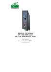
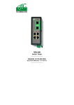
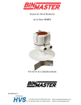
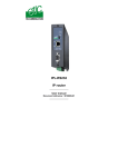
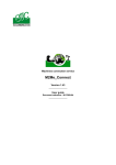
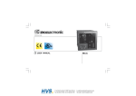
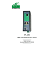
Distribué par :
Contact :
[email protected]
Tél : 0326824929
Fax : 0326851908
Siège social :
2 rue René Laennec
51500 Taissy
France
www.hvssystem.com
XSLAN-140
SHDSL Switch
_________________
User manual
Document reference : 9017209-01
_________________
The XSLAN-140 SHDSL switch is manufactured by
ETIC TELECOMMUNICATIONS
13 Chemin du vieux chêne
38240 MEYLAN
FRANCE
TEL : + 33 4-76-04-20-00
FAX : + 33 4-76-04-20-01
e-mail : [email protected]
web : www.etictelecom.com
Hotline
TEL : + 33 4-76-04-20-05
FAX : + 33 4-76-04-20-01
e-mail : [email protected]
Page 2
User manual ref 9017209-01
XSLAN-140 shdsl switch
CONTENT
OVERVIEW
1
2
3
DELIVERY CONTENT ........................................................................................5
PRODUCT OVERVIEW.......................................................................................5
DATA SHEET......................................................................................................6
INSTALLATION
1
2
3
4
5
6
PRODUCT DESCRIPTION .................................................................................7
1.1 Leds ......................................................................................8
1.2 Connectors...........................................................................9
1.3 DIP switches ......................................................................10
VENTILATION...................................................................................................11
SUPPLY VOLTAGE..........................................................................................11
FUSE .................................................................................................................11
ETHERNET PORTS..........................................................................................11
SHDSL LINE CONNECTION ............................................................................12
STARTUP
1
SETTING UP THE SHDSL CONNECTION .....................................................13
DIAGNOSTIC & MAINTENANCE
1
2
3
4
CONNECTING A PC TO THE XSLAN SERVER..............................................16
1.1 Connecting the PC directly to the Ethernet RJ45 of the
XSLAN ........................................................................................16
1.2 Connecting a PC through a LAN.....................................16
1.3 Wrong IP address or password .......................................17
CHECKING THE TRANSMISSION QUALITY..................................................18
CHECKING SHDSL LINE DISCONNECTIONS ...............................................18
UPDATING THE FIRMWARE...........................................................................19
Appendix 1 :
Data rate versus line lenght and cable quality
XSLAN-140 shdsl switch
User manual ref 9017209-01
Page 3
Page 4
User manual ref 9017209-01
XSLAN-140 shdsl switch
OVERVIEW
1
Delivery content
Switch SHDSL
Câble pour ligne SHDSL
User manual
1
1
1
Accessories to order separately
Additional surge voltage arrester
2
reference
PS02-1
Product overview
The XSLAN-140 shdsl switch enables to extend an Ethernet network
over kilometres using one simple voice-grade twisted pairs
(telephone line).
Distance and data rate
SHDSL features an adaptive data rate from 128 Kb/s up to 2.3 Mb/s.
The data rate is a function of the cable quality and the distance with the
other SHDSL switch. For instance, the maximum distance between 2
switches through a line is 13 Km (8 miles) with a 0.9 mm wire diameter
cable.
The table in appendix 1 gives the data rate which can be expected over a
line versus the length of the line (distance between 2 switches).
Ethernet ports
The XSLAN-140 provides 4 ethernet RJ45 interfaces (depending on the
product reference).
DIP swithes configuration
The XSLAN-140 is configured with a few DIP switches.
An html server for diagnostic
The XSLAN-140 html server provides diagnostic pages giving the
guarantee the transmission quality is what it has to be.
XSLAN-140 shdsl switch
User manual ref 9017209-01
Page 5
OVERVIEW
3
Data sheet
Dimensions
137 x 48 x 116 mm (h, l, d)
C.E.M
EN50082-2
Electrical safety
EN 60950
Thunder
Supply voltage
EN61000-4 et -5
9 to 40 VDC
Consumption
4W
Operating T°
-20°/ + 60°C non condensing
SHDSL
Connection delay
Latency delay
through the line
Ethernet
Switch
ITU-T G.991.2, 802.3ah : 2BaseTL (EFM)
Data rate : 128 kb/s to 2.3 Mb/s with 2 wires
Auto-mode : 1 mn
Fixed data rate : 30 s
4 ms at 2.3Mb/s
6 ms at 512 kb/s
4 RJ45 10/100 Mb/s Half/Full duplex Auto MDI/MDIX
Store and forward - 1024 MAC @
Configuration
Dip switches
Diagnostic
Html server
Page 6
User manual ref 9017209-01
XSLAN-140 Shdsl switch
INSTALLATION
1
Product description
XSLAN-140 shdsl switch
User manual ref 9017209-01
Page 7
INSTALLATION
1.1
Leds
OPERATION led
SHDSL Errors
port 1 & port 2
Not used
SHDSL connection
leds
1
SHDSL
Ethernet activity led
port 1 & port 2
10 / 100 BT
Ethernet activity led
port 3 & port 4
Function
Ethernet
Shdsl line led
Shdsl error led
Operation
Page 8
1
2
3
4
Led
LINK/DATA
Description
Ethernet activity
Green lower led :
Slowly blinking : Shdsl connection in process
Lit on : Shdsl connection set
Quickly blinking : Traffic over the SHDSL link
Red upper led :
Off : Error-free transmission
Quickly blinking : Transmission errors
Green : Ready for use
Red : Alarm
User manual ref 9017209-01
XSLAN-140 Shdsl switch
INSTALLATION
1.2
Connectors
8 pins screw block
Supply voltage and input / output
Pin Nr
Signal
1
2
3
4
5
6
7
8
Power 1 +
Power 1 Power 2 +
Power 2 -
Supply voltage input 1 : 9 to 30 Vdc
0V
Supply voltage input 2 : 9 to 30 Vdc
0V
Pin Nr
Signal
SHDSL RJ45 connector
Function
1
2
3
4
5
6
7
8
N.C.
N.C.
N.C.
TIP
RING
N.C.
N.C.
N.C.
Pin Nr
Signal
1
2
3
4
5
6
7
8
Tx +
Tx Rx +
N.C
N.C
Rx N.C.
N.C.
XSLAN-140 shdsl switch
Function
SHDSL line
SHDSL line
-
Ethernet RJ45 connector
Function
TX polarity +
TX polarity Reception polarity +
Reception polarity -
User manual ref 9017209-01
Page 9
INSTALLATION
1.3
DIP switches
DIP switches
SW 1 SW 2 Management
OFF
OFF The current IP@ of the product is the stored IP @
ON
OFF
The active IP@ of the product is the factory IP@ : 192.168.0.128
No login and password are required to access to the html server
OFF
ON
The active IP@ is provided by the BOOTP or DHCP server
ON
ON
No IP @ is assigned to the product; DIP switch configuration
SW 3 SW 4 SW 5 Shdsl port
OFF
OFF
OFF NTU mode
OFF
OFF
ON
OFF
ON
OFF LTU mode – 2304 kbit/s
OFF
ON
ON
ON
OFF
OFF LTU Mode – 1536 kbit/s
ON
OFF
ON
ON
ON
OFF LTU Mode – 512 kbit/s
ON
ON
ON
LTU mode - Auto
LTU Mode – 2048 kbit/s
LTU Mode – 1024 kbit/s
LTU Mode – 256 kbit/s
SW 6 to SW
Not used - Must be left OFF
12
Page 10
User manual ref 9017209-01
XSLAN-140 Shdsl switch
INSTALLATION
2
Ventilation
To avoid overheating when the ambient temperature is high, leave a 1 cm
(0.5 inch) space on each side of the product.
3
Supply voltage
The product comes with 2 separate voltage inputs, so that 2 external
power supply modules can be connected to the product. If one power
supply module fails, the XSLAN-140 will be powered by the other.
The supply voltage must be strictly lower than 30 VDC and higher than 9
VDC. The consumption is 170 mA at 24 VDC.
4
Fuse
The product is protected with a 3A fuse located on the electronic board
near the supply voltage connectors.
!!! A replacement fuse is available on the board ; it is located over the leds.
5
Ethernet ports
The XSLAN-140 features two or four auto-sensing 10/100 Mbps
MDI/MDIX LAN ports.
XSLAN-140 shdsl switch
User manual ref 9017209-01
Page 11
INSTALLATION
6
SHDSL line connection
The XSLAN-140 is delivered with 1 line cable (reference CAB614).
That cable ends with 2 wires.
The 2 wires have to be connected to the 2 wires of the twisted pair line.
The wires can be inverted.
Shield :
If the cable is shielded, the shield must be connected, at one end, directly
to the earth.
Surge voltage arrester
if the line is exposed to the
lightning, we advise to use
an over voltage arrester at
each end of the line.
We have selected the Phoenix Contact
module TT-2-PE-24D; it must be wired as
indicated opposite.
Page 12
User manual ref 9017209-01
XSLAN-140 Shdsl switch
STARTUP
1
Setting up the SHDSL connection
The XSLAN-140 is configured with DIP switches.
The DIP swiches are located on the top side of the product.
In case of difficulties, the diagnostic html server offers very useful
diagnostic functions like Error rate statistics, signal quality and connection
logs.
To access to the html server, an IP address must be assigned to the
product.
Step 1 : Adjusting the “management” DIP switches SW01 and SW02
settings
SW01 and SW02 must be usually set ON and ON. In that case, no IP
address is assigned to the product.
However, in case of line disconnection or errors, the html diagnostic
server will help to solve the difficulties; in that case, an IP address can be
assigned to the product according to the table below.
DIP switches
SW 1 SW 2 Management
OFF
OFF The current IP@ of the product is the stored IP @
ON
OFF
The active IP@ of the product is the factory IP@ : 192.168.0.128
No login and password are required to access to the html server
OFF
ON
The active IP@ is provided by the BOOTP or DHCP server
ON
ON
No IP @ is assigned to the product; DIP switch configuration
XSLAN-140 shdsl switch
User manual ref 9017209-01
Page 13
STARTUP
Step 2 : Adjusting the “SHDSL” DIP-switches SW3, SW4, SW5
settings
When 2 XSLAN-140 are connected to one another
through a line, one has to be configured as an LTU
(calling party) and the other one as an “NTU”. (called
party).
The product which is named “LTU” negotiates and
forces the data rate over the line; the NTU can only
accept.
Setting up the XSLAN-140 1 (LTU) :
If SW3, SW4 and SW5 are set OFF, OFF and ON (auto mode), the
XSLAN 1 (LTU) will negotiate the appropriate data rate with the XSLAN 2
(NTU). The connection delay will be longer.
To reduce the connection delay, select the appropriate position of SW03,
SW04, SW05 according to the line length; Refer to the table in appendix
1.
XSLAN 1
SW 3 SW 4 SW 5 Shdsl port
OFF
OFF
ON
OFF
ON
OFF LTU mode – 2304 kbit/s
OFF
ON
ON
ON
OFF
OFF LTU Mode – 1536 kbit/s
ON
OFF
ON
ON
ON
OFF LTU Mode – 512 kbit/s
ON
ON
ON
Page 14
LTU mode – Auto
LTU Mode – 2048 kbit/s
LTU Mode – 1024 kbit/s
LTU Mode – 256 kbit/s
User manual ref 9017209-01
XSLAN-140 Shdsl switch
STARTUP
Setting up the XSLAN 2 :
XSLAN 2
SW 3 SW 4 SW 5 Shdsl port
OFF
OFF
OFF NTU mode
Step 3 : Connecting the products to the line
Connect the products to the line using the CAB 614 cable.
Nota bene : For test purposes, any straight RJ45 cable can be connected
to each XSLAN-140 SHDSL RJ45 connector.
Step 4 : Check the connection
The lower green led of the SHDSL RJ45 connector blinks during the
SHDSL negotiation and then remains lit when the connection is
established.
If the Line led (lower green led of the SHDSL RJ45 connector)
blinks permanently, it means that the connection cannot be
established; check the wires connection and eventually, set a lower
data rate with the DIP switches SW03, SW04, SW05.
If the Error led (upper red led of the SHDSL RJ45 connector)
blinks, it means that errors occur on the line, check the wires
connection and eventually, set a lower data rate with the DIP switches
SW03, SW04, SW05.
Step 5 : exchange data through the line
Connect a PC to one of the XSLAN-140 and transmit periodical PING to
the other XSLAN-140.
Check an answer is received within less than 10 ms.
XSLAN-140 shdsl switch
User manual ref 9017209-01
Page 15
MAINTENANCE
1
1.1
Connecting a PC to the XSLAN server
Connecting the PC directly to the Ethernet RJ45 of the XSLAN
Step 1 : Check the DIP switches SW1 and SW2; they must be set to OFF
and OFF to select the stored IP address, or, if necessary, to ON and OFF
to restore the factory IP address.
Coming from factory, the IP address of the XSLAN-140 is 192.168.0.128.
Step 2 : Create or modify the PC TCP/IP connection
Assign to the PC an IP @ in accordance with the XSLAN-140 IP address.
For the first configuration, assign or instance 192.168.0.127 to the PC.
Step 3 : Connect the PC directly
to an XSLAN ethernet interface
using any Ethernet cable (straight
or crosswired)
Step 4 : Launch the html browser
Enter the IP @ of the XSLAN-140.
The Home page of the
administration server is displayed
1.2
Connecting a PC through a LAN
Case of a LAN with a BOOTP or DHCP server
Step 1 : Set the DIP switches SW1 OFF and SW2 OFF to select DHCP /
BOOTP operation.
Step 2 : Launch ETIC FINDER to detect the XSLAN over the LAN.
XSLAN-140 shdsl switch
User manual ref 9017209-01
Page 16
MAINTENANCE
Click the product once detected.
The Home page of the administration server is displayed.
Note :
If the home page cannot be displayed, refer to paragraph 4 below.
Case of a LAN without BOOTP or DHCP server
That method must be avoided for the first configuration, because the
factory IP address of the XSLAN-140 can also have been assigned to
another product.
Otherwise, launch the html browser and enter the IP address assigned to
the XSLAN-140.
Or, launch the ETICFINDER utility.
1.3
Wrong IP address or password
When launching the html browser, the homepage of the html server may
not be displayed; the cause may be the IP address you enter or the
password you use are wrong.
if the XSLAN-140 IP address you enter is wrong, you can recover the
factory IP address by setting SW01 ON and SW2 OFF.
The factory IP address 192.168.0.128 will be restored as long as the
SW01 micro-switch will be left ON. Once, SW01 will be set OFF, the
stored IP address (the IP address which is displayed) will be used by the
product.
Wrong Login to the administration server
The access to the administration server can be protected by a login and
password; If the Login & or password entered to access to the
administration server have been rejected, it is possible to recover a free
access, by setting SW01 ON and SW2 OFF.
Careful : The factory IP address 192.168.0.128 will also automatically be
assigned to the product as long as SW01 will remain ON and SW2 OFF.
XSLAN-140 shdsl switch
User manual ref 9017209-01
Page 17
MAINTENANCE
2
Checking the transmission quality
The transmission quality can be summarized by two data :
The signal quality and the error rate.
Select the Diagnostic menu and then Network status.
Signal quality
Once the connection is set, the “Link state” line gives the signal quality
from 1/5 (bad quality), to 5/5 (excellent).
If the signal quality is 1/5 or 2/5, errors and disconnection can occur;
decrease the data rate (DIP switches of the XSLAN-140 declared as LTU)
and check the line.
If the signal quality is 3/5, the connection quality is sufficient. Nevertheless
the data rate can be decreased with the DIP switches to get a 4/5 signal
quality.
SHDSL errors rate
To check the error rate, click the “Show statistics” button.
Click the Reset button to reset the counters.
The “CRC SHDSL errors” counter gives the numbers of errors on the line.
If the quality is good, the number of errors must not increase more than
once every minute.
3
Checking SHDSL line disconnections
The log menu shows dated connections and disconnections of the
XSLAN-140.
When the quality is good, the XSLAN-140 must not disconnect.
Page 18
User manual ref 9017209-01
XSLAN-140 shdsl switch
MAINTENANCE
4
Updating the firmware
Step 1 : Before starting, you need,
A PC with a Web browser.
An Ethernet cable or a switch
The FTP server software which can be downloaded from the « firmware
page » of the ETIC « download area » web server.
Step 2 : Download the release of the firmware from our download
area to your PC
Step 3 : Prepare the PC
Check the Ip address of the PC is compatible with the one of the router.
Connect the router to the PC.
Launch the TFTP server (tftp32.exe) software and select the new release
(L026xxx/img) by using the "Browser" button.
Click on "Show dir" to check the files of the directory : (jffs2root,
rfsmini.tgz, u-boot.bin and uImage).
Step 4 : Update the firmware
Launch the web browser
Enter the IP address of the ETIC product ; the home page of the ETIC
configuration server is displayed.
Select the "System" menu and then " firmware Update". In the field "IP
address of the TFTP server", enter the IP address of your PC.
Note : The IP address of the PC is written in the field "Server Interface" in
the TFTP server windows.
Click "Save" and then "Update".
The first file should begin to be downloaded from the PC to the router.
During the operation, the led blinks
When the download is finished, the product automatically reboots.
To be sure the new release has been installed, go to "About" in the
administration web page of the IP product.
XSLAN-140 shdsl switch
User manual ref 9017209-01
Page 19
APPENDIX 1
Data rate versus line length and cable quality
Distance (Km)
Wire diam.
mm
3
4
6
7
8
10
12
0,9 2.3Mb/s
2.3Mb/s
2.3Mb/s
1.5Mb/s
1.1Mb/s
512Kb/s
128Kb/s
0,6 2.3Mb/s
2.3Mb/s
1.1Mb/s
256Kb/s
128Kb/s
0,4 2.3Mb/s
1.1Mb/s
256Kb/s
128Kb/s
XSLAN-140 shdsl switch
User manual ref 9017209-01
Page 21
Distribué par :
Contact :
[email protected]
Tél : 0326824929
Fax : 0326851908
Siège social :
2 rue René Laennec
51500 Taissy
France
www.hvssystem.com
ETIC TELECOM
13 chemin du vieux chêne
38240 Meylan -France
Tel 33 4 76 04 20 00
Fax 33 4 76 04 20 01
email : [email protected]
Web : www.etictelecom.com