1
Cisco Structured Wireless-Aware
Network (SWAN) Implementation Guide
January 2005
Corporate Headquarters
Cisco Systems, Inc.
170 West Tasman Drive
San Jose, CA 95134-1706
USA
http://www.cisco.com
Tel: 408 526-4000
800 553-NETS (6387)
Fax: 408 526-4100
Text Part Number: OL-6217-01
THE SPECIFICATIONS AND INFORMATION REGARDING THE PRODUCTS IN THIS MANUAL ARE SUBJECT TO CHANGE WITHOUT NOTICE. ALL
STATEMENTS, INFORMATION, AND RECOMMENDATIONS IN THIS MANUAL ARE BELIEVED TO BE ACCURATE BUT ARE PRESENTED WITHOUT
WARRANTY OF ANY KIND, EXPRESS OR IMPLIED. USERS MUST TAKE FULL RESPONSIBILITY FOR THEIR APPLICATION OF ANY PRODUCTS.
THE SOFTWARE LICENSE AND LIMITED WARRANTY FOR THE ACCOMPANYING PRODUCT ARE SET FORTH IN THE INFORMATION PACKET THAT
SHIPPED WITH THE PRODUCT AND ARE INCORPORATED HEREIN BY THIS REFERENCE. IF YOU ARE UNABLE TO LOCATE THE SOFTWARE LICENSE
OR LIMITED WARRANTY, CONTACT YOUR CISCO REPRESENTATIVE FOR A COPY.
The following information is for FCC compliance of Class A devices: This equipment has been tested and found to comply with the limits for a Class A digital device, pursuant
to part 15 of the FCC rules. These limits are designed to provide reasonable protection against harmful interference when the equipment is operated in a commercial
environment. This equipment generates, uses, and can radiate radio-frequency energy and, if not installed and used in accordance with the instruction manual, may cause
harmful interference to radio communications. Operation of this equipment in a residential area is likely to cause harmful interference, in which case users will be required
to correct the interference at their own expense.
The following information is for FCC compliance of Class B devices: The equipment described in this manual generates and may radiate radio-frequency energy. If it is not
installed in accordance with Cisco’s installation instructions, it may cause interference with radio and television reception. This equipment has been tested and found to
comply with the limits for a Class B digital device in accordance with the specifications in part 15 of the FCC rules. These specifications are designed to provide reasonable
protection against such interference in a residential installation. However, there is no guarantee that interference will not occur in a particular installation.
Modifying the equipment without Cisco’s written authorization may result in the equipment no longer complying with FCC requirements for Class A or Class B digital
devices. In that event, your right to use the equipment may be limited by FCC regulations, and you may be required to correct any interference to radio or television
communications at your own expense.
You can determine whether your equipment is causing interference by turning it off. If the interference stops, it was probably caused by the Cisco equipment or one of its
peripheral devices. If the equipment causes interference to radio or television reception, try to correct the interference by using one or more of the following measures:
• Turn the television or radio antenna until the interference stops.
• Move the equipment to one side or the other of the television or radio.
• Move the equipment farther away from the television or radio.
• Plug the equipment into an outlet that is on a different circuit from the television or radio. (That is, make certain the equipment and the television or radio are on circuits
controlled by different circuit breakers or fuses.)
Modifications to this product not authorized by Cisco Systems, Inc. could void the FCC approval and negate your authority to operate the product.
The Cisco implementation of TCP header compression is an adaptation of a program developed by the University of California, Berkeley (UCB) as part of UCB’s public
domain version of the UNIX operating system. All rights reserved. Copyright © 1981, Regents of the University of California.
NOTWITHSTANDING ANY OTHER WARRANTY HEREIN, ALL DOCUMENT FILES AND SOFTWARE OF THESE SUPPLIERS ARE PROVIDED “AS IS” WITH
ALL FAULTS. CISCO AND THE ABOVE-NAMED SUPPLIERS DISCLAIM ALL WARRANTIES, EXPRESSED OR IMPLIED, INCLUDING, WITHOUT
LIMITATION, THOSE OF MERCHANTABILITY, FITNESS FOR A PARTICULAR PURPOSE AND NONINFRINGEMENT OR ARISING FROM A COURSE OF
DEALING, USAGE, OR TRADE PRACTICE.
IN NO EVENT SHALL CISCO OR ITS SUPPLIERS BE LIABLE FOR ANY INDIRECT, SPECIAL, CONSEQUENTIAL, OR INCIDENTAL DAMAGES, INCLUDING,
WITHOUT LIMITATION, LOST PROFITS OR LOSS OR DAMAGE TO DATA ARISING OUT OF THE USE OR INABILITY TO USE THIS MANUAL, EVEN IF CISCO
OR ITS SUPPLIERS HAVE BEEN ADVISED OF THE POSSIBILITY OF SUCH DAMAGES.
CCSP, the Cisco Square Bridge logo, Cisco Unity, Follow Me Browsing, FormShare, and StackWise are trademarks of Cisco Systems, Inc.; Changing the Way We Work,
Live, Play, and Learn, and iQuick Study are service marks of Cisco Systems, Inc.; and Aironet, ASIST, BPX, Catalyst, CCDA, CCDP, CCIE, CCIP, CCNA, CCNP, Cisco,
the Cisco Certified Internetwork Expert logo, Cisco IOS, Cisco Press, Cisco Systems, Cisco Systems Capital, the Cisco Systems logo, Empowering the Internet Generation,
Enterprise/Solver, EtherChannel, EtherFast, EtherSwitch, Fast Step, GigaDrive, GigaStack, HomeLink, Internet Quotient, IOS, IP/TV, iQ Expertise, the iQ logo, iQ Net
Readiness Scorecard, LightStream, Linksys, MeetingPlace, MGX, the Networkers logo, Networking Academy, Network Registrar, Packet, PIX, Post-Routing, Pre-Routing,
ProConnect, RateMUX, Registrar, ScriptShare, SlideCast, SMARTnet, StrataView Plus, SwitchProbe, TeleRouter, The Fastest Way to Increase Your Internet Quotient,
TransPath, and VCO are registered trademarks of Cisco Systems, Inc. and/or its affiliates in the United States and certain other countries.
All other trademarks mentioned in this document or Website are the property of their respective owners. The use of the word partner does not imply a partnership relationship
between Cisco and any other company. (0406R)
Cisco Aironet 1400 Series Wireless Bridge Deployment Guide
Copyright © 2004 Cisco Systems, Inc. All rights reserved.
C ON T E N T S
Audience
5
Acronyms and Terms
6
Cisco SWAN Framework Overview 7
CISCO SWAN Framework Components
Software Components 12
Hardware Components 12
11
Implementing the Cisco SWAN Framework 13
Common Tasks 14
Configuring the CiscoSecure ACS Server for Infrastructure Authentication 14
Configuring the Local RADIUS Server on the Access Point for Infrastructure Authentication
Configuring the AAA Server to Support WLAN Client Authentication 18
Preparing the CiscoWorks WLSE for Managing WLAN Devices 18
Distributed WDS Solution Configuration 21
Configuring the WDS Access Point 21
Configuring the Infrastructure Access Point 23
Managing the Access Points with the CiscoWorks WLSE 24
Validating the Configuration 24
Infrastructure Integrated WDS Solution Configuration 25
Configuring the Catalyst 6500 Supervisor 720 25
Configuring the WDS on the WLSM 26
Configuring the Infrastructure Access Points 27
Managing the WLSM and Access Points with the CiscoWorks WLSE 28
Validating the Setup 29
Fast Secure Roaming with Cisco Centralized Key Management (CCKM) 30
When Not Using Multiple Encryption Types 31
When Using Multiple Encryption Types 31
Configuring ACU to use CCKM 32
Cisco SWAN Radio Management Features 33
Preparing to Use Cisco SWAN Radio Management 34
Cisco SWAN Radio Management Features 35
Conclusion 37
Book Title
78-xxxxx-xx
iii
18
Contents
Book Title
iv
78-xxxxx-xx
Cisco Structured Wireless-Aware Network
(SWAN) Implementation Guide
The Cisco Structured Wireless-Aware Network (SWAN) provides the framework to integrate and extend
wired and wireless networks to deliver the lowest possible total cost of ownership for companies
deploying wireless LANs (WLANs). Cisco SWAN extends “wireless awareness” into important
elements of the network infrastructure, providing the same level of security, scalability, reliability, ease
of deployment, and management for wireless LANs that organizations have come to expect from their
wired LANs.
This document provides a brief technical synopsis of the Cisco SWAN framework and functionality and
provides details on implementing the solution.
Audience
The audience for this document is Cisco Systems Engineers, Consulting Systems Engineers, Product
Sales Specialists, and Cisco customers implementing and evaluating the Cisco SWAN framework.
This document is not an extensive theoretical discussion on the Cisco SWAN framework; it is intended
as a reference to outline the implementation procedures for selected Cisco SWAN components, features,
and capabilities.
For a detailed review of Cisco SWAN features and benefits, read the Cisco SWAN brochure at:
http://www.cisco.com/en/US/products/hw/wireless/ps430/prod_brochure09186a0080184925.html
Or visit the Cisco SWAN website:
http://www.cisco.com/go/swan
Cisco Structured Wireless-Aware Network (SWAN) Implementation Guide
OL-6217-01
5
Cisco Structured Wireless-Aware Network (SWAN) Implementation Guide
Acroymns and Terms
Acroymns and Terms
Table 1
Acronyms, Terms, and Definitions
Term
Definition
Cisco SWAN
Cisco Structured Wireless Aware Network—Cisco’s
framework for delivering integrated wired and wireless LAN
networks.
WDS
Wireless Domain Service — Cisco IOS software functionality
enabling advanced Cisco SWAN functionality.
WLCCP
Wireless LAN Context Control Protocol —A Cisco-defined
control protocol for Cisco SWAN.
RM
Radio Management — Access points participating in radio
management scan the radio environment and send reports to
the WDS device on such radio information as potential rogue
access points, associated clients, client signal strengths, and
the radio signals from other access points.
AAA
Authentication Authorization and Accounting — A common
acronym used to describe secure network access services.
CiscoWorks WLSE
CiscoWorks Wireless LAN Solution Engine — A component
of the Cisco SWAN framework that provides many features for
managing the wireless LAN, including making configuration
changes, providing reports, collecting radio monitoring and
management information, and performing device discovery.
ACS
CiscoSecure Access Control Server — An optional AAA
product from Cisco that is often used with the Cisco SWAN
framework.
WLSM
Wireless LAN Service Module — A service module
component of the Cisco SWAN framework. The WLSM is a
member of the Catalyst 6500 service module family that
enables the Cisco SWAN switch-based WDS architecture.
Client
A wireless end-user device such as a laptop computer, PDA, or
wireless IP phone.
MN
Mobile Node — In Cisco SWAN framework terminology, a
mobile node is a valid, authenticated wireless client device.
Infrastructure Access
Point
In the Cisco SWAN framework, an infrastructure access point
is an access point that is registered with a WDS-host device
and can deliver Cisco SWAN functionality.
WLAN Control Domain A WLAN control domain consists of a WDS-host device, its
registered infrastructure access points, and all of its mobile
nodes.
WDS Host
An IOS-based Cisco device hosting WDS that is either a Cisco
Aironet Access Point or the WLSM.
Cisco Structured Wireless-Aware Network (SWAN) Implementation Guide
6
OL-6217-01
Cisco Structured Wireless-Aware Network (SWAN) Implementation Guide
Cisco SWAN Framework Overview
Table 1
Acronyms, Terms, and Definitions
Term
Definition
Access Point-Based
WDS Architecture
The Access Point-Based WDS architecture is an architecture
with Layer 2 WLAN control domains, where WDS is hosted
on Cisco Aironet access points.
Switch-Based WDS
Architecture
The Switch-Based WDS architecture is an architecture with
Layer 3 WLAN control domains, where the WDS is hosted on
the WLSM.
mGRE
Multipoint Generic Route Encapsulation — A tunneling
encapsulation type defined by IETF RFC that is leveraged by
the Cisco SWAN framework switch-based WDS solution.
CCKM
Cisco Centralized Key Management — A Cisco- defined
encryption key management scheme that enables fast secure
roaming within a WLAN control domain.
802.1X/EAP
802.1X is an IEEE defined mechanism for port access control,
and extensible authentication protocol (EAP) is an
authentication protocol defined by IETF RFC. EAP is generic
enough to be implemented in a number of ways, including
Cisco LEAP, EAP-FAST, PEAP, EAP-TLS, and EAP-TTLS.
The combination of 802.1X port access control and EAP
authentication type is used to secure access to the WLAN.
Cisco LEAP
A Cisco-defined EAP type for secure access to the WLAN
EAP-FAST
A Cisco-defined EAP type for secure access to the WLAN
ACU
Cisco Aironet Client Utility
ADU
Cisco Aironet Desktop Utility
Cisco SWAN Framework Overview
Cisco SWAN provides the framework to integrate and extend wired and wireless networks to deliver the
lowest possible total cost of ownership for companies deploying WLANs. Cisco SWAN extends
"wireless awareness" into important elements of the network infrastructure, providing the same level of
security, scalability, reliability, ease of deployment, and management for wireless LANs that
organizations have come to expect from their wired LANs.
The Cisco SWAN framework addresses two key issues with managing and operating WLANs: fast secure
WLAN client roaming and radio management. Fast secure roaming allows WLAN clients to move
association from one access point to another with little or no service disruption. Cisco SWAN radio
management characterizes the radio transmission environment and responds to the conditions of the
environment.
The Cisco SWAN framework can be visualized as a layered model. The Cisco SWAN framework layers
are:
•
Management Layer
•
Wireless Domain Services Layer
•
Infrastructure Access Point Layer
•
Wireless Client Layer
Cisco Structured Wireless-Aware Network (SWAN) Implementation Guide
OL-6217-01
7
Cisco Structured Wireless-Aware Network (SWAN) Implementation Guide
Cisco SWAN Framework Overview
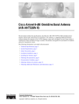
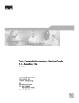
The Cisco SWAN framework introduces WLCCP to facilitate control messaging between the framework
components. Figure 1 illustrates the conceptual model of the Cisco SWAN framework, including the
WLCCP messaging protocol. As shown in Figure 1, each layer is implemented in specific Cisco
products.
Figure 1
Cisco SWAN Layers
The management layer supplies the processing of RM data from the lower layers, controlling and
managing the radio coverage environment. This data is also used for securing the radio coverage
environment by detecting rogue access points and wireless clients. Authentication, Authorization, and
Accounting (AAA) services are also placed in the management layer.
The required management layer component is the CiscoWorks WLSE. An optional component is the
CiscoSecure ACS. Other products with functionality equivalent to ACS may be used in Cisco SWAN.
The WDS layer provides critical services: WLAN client context awareness, fast secure roaming, and
aggregation of radio management data from the infrastructure access point and client layer. WDS is
implemented in supporting versions of Cisco IOS for the Cisco Aironet 1100 and 1200 series access
points and on the special Cisco IOS running on the wireless LAN service module for the Catalyst 6500
switch platform. The solution architecture dictates whether to use the WDS access point or the WLSM
implementation.
The infrastructure access point layer facilitates WLAN client access to the wired-network, radio
downlink encryption, and radio management data collection, including on-going radio monitoring.
The client layer includes all wireless clients. Advanced SWAN framework features take advantage of
client-side capabilities to allow for radio measurement collection from the WLAN clients and fast secure
roaming.
Cisco Structured Wireless-Aware Network (SWAN) Implementation Guide
8
OL-6217-01
Cisco Structured Wireless-Aware Network (SWAN) Implementation Guide
Cisco SWAN Framework Overview
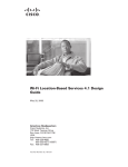
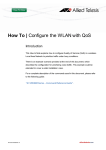
Figure 2 represents a logical, hierarchical view of the SWAN framework that clearly illustrates the
importance of the WDS layer.
Figure 2
Cisco SWAN Logical View
ACS
WLSE
WLCCP messages
RADIUS control
domain
WDS
WLAN control
domain
WLCCP
messages
WDS
802.1x
authenticator
WLCCP
messages
WLAN control
domain
IP
127430
Data
packets
IP
WDS are configured to run on a supporting device—either a Cisco Aironet 1100 or 1200 for a Layer 2
architectural solution or the WLSM for an switch-based, Layer 3 solution. In both cases, infrastructure
access points register with the WDS using special WLCCP messages.
Once registered, the infrastructure access points forward client association, authentication, and roaming
information through the WDS via WLCCP MN registration messages, allowing the WDS to control and
track wireless clients. If client authentication is implemented via any 802.1x with EAP (such as Cisco
LEAP, EAP-FAST, PEAP, EAP-TLS, or EAP-TTLS), the WDS performs an additional important role by
acting as the 802.1x authenticator for all wireless clients. In 802.1x authentication transactions, the WDS
communicates directly with the RADIUS server. Any valid wireless client associated with an
infrastructure access point and registered with the WDS.
A WDS, its registered infrastructure access points, and registered clients make up a WLAN control
domain. Wireless clients can seamlessly roam between access points within a WLAN control domain. A
WDS also collects radio management data from the infrastructure access points and, potentially, the
MNs within the WLAN control domain via special WLCCP radio management (WLCCP-RM)
messages. This data is aggregated by the WDS and passed on to the WLSE in WLCCP-RM messages.
The WLSE uses this RM data to control and manage the radio coverage environment and to detect rogue
access points and clients.
Cisco SWAN offers two basic WLAN architectures: an architecture supporting a Layer 2 WLAN control
domain and an architecture supporting a Layer 3 WLAN control domain. The Layer 2 architecture
leverages access point-based WDS. This architecture is called the access point-based WDS solution. The
Layer 3 architecture leverages WLSM-based WDS and is called the switch-based WDS solution.
Cisco Structured Wireless-Aware Network (SWAN) Implementation Guide
OL-6217-01
9
Cisco Structured Wireless-Aware Network (SWAN) Implementation Guide
Cisco SWAN Framework Overview
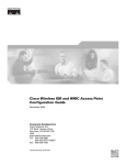
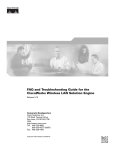
Figure 3 shows the access point-based WDS solution.
Figure 3
Access Point-Based WDS Solution
In the access point-based WDS solution, infrastructure access points discover the WDS via special
WLCCP multicast messages. You must have an access point running WDS on each Layer 2 subnet. The
solution supports up to 30 infrastructure access points when the WDS-host access point is also serving
wireless clients and up to 60 infrastructure access points when the WDS-host access point is not serving
wireless clients. The access point-based WDS solution facilitates seamless MN roaming across a Layer
2 WLAN control context.
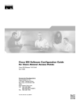
Figure 4 shows the switch-based WDS solution.
Cisco Structured Wireless-Aware Network (SWAN) Implementation Guide
10
OL-6217-01
Cisco Structured Wireless-Aware Network (SWAN) Implementation Guide
Cisco SWAN Framework Overview
Figure 4
Switch-Based WDS Solution
In the switch-based WDS solution, mGRE tunnels are built from the Catalyst 6500 switch hosting the
WLSM where the WDS is running. Wireless client data is tunneled to the Catalyst 6500 switch where it
is forwarded appropriately. The mGRE tunnel legs are built when the infrastructure access points register
with the WDS on the WLSM. Wireless client authentication and MN registration WLCCP messages are
forwarded to the WLSM for centralized processing. Unlike wireless client data traffic, WLCCP
messages are not forwarded on the mGRE tunnel legs. Rather, these messages traverse the network like
standard IP packets. The switch-based WDS architecture offers complete control and data plane
separation, which are essential elements to true network scalability. The switch-based WDS solution
facilitates seamless roaming across a Layer 3 WLAN control context and supports up to 300 registered
infrastructure access points and 6000 MNs per WLSM.
CISCO SWAN Framework Components
The Cisco SWAN framework has software and hardware components.
The software components are:
•
WDS
•
WLCCP
The hardware components are:
•
WDS-host devices
•
Infrastructure access points
Cisco Structured Wireless-Aware Network (SWAN) Implementation Guide
OL-6217-01
11
Cisco Structured Wireless-Aware Network (SWAN) Implementation Guide
Cisco SWAN Framework Overview
•
WLSE
•
Cisco and Cisco compatible clients
Software Components
There are two software components essential to the operation of the Cisco SWAN framework: WDS and
WLCCP.
WLCCP
WLCCP is a Cisco-defined control protocol that allows control communication between the Cisco
SWAN components. WLCCP messages are used to authenticate and register Cisco SWAN components,
constructing the Cisco SWAN control topology. The WLCCP messages are used in WLAN client
association and authentication, and re-association and re-authentication during client roaming.
WLCCP-RM is used to transfer radio measurement data between the Cisco SWAN components. A
technical discussion of WLCCP is beyond the scope of this document.
WDS
WDS are a set of IOS services that define a WLAN control domain. Within a WLAN control domain,
all infrastructure access points register with the WDS. After registration, 802.1x WLAN client
authentications are forwarded through the WDS. Infrastructure access points register their associated
WLAN clients with the WDS, so the WDS tracks all WLAN clients within the WLAN control domain.
WDS also collects radio management data from infrastructure access points (and optionally mobile
nodes), aggregates data, and forwards them to the CiscoWorks WLSE for intelligent processing. WDS
can be implemented on an access point or on the WLSM.
Hardware Components
The hardware required to implement the Cisco SWAN framework includes WDS hosting devices,
infrastructure access points, and the CiscoWorks WLSE. Optional hardware components include WLAN
client devices: Cisco Aironet client adapters and devices certified as part of the Cisco Compatible
Extensions program.
WDS-Host Devices
WDS can be hosted on an access point or on the WLSM. WDS is supported on the Cisco Aironet 1100
and 1200 series IOS-based access points for the access point-based WDS solution. WDS is supported on
the WLSM for the switch-based WDS solution.
Infrastructure Access Points
Infrastructure access points register with the WDS within the WLAN control domain. The Cisco Aironet
350, 1100, and 1200 series IOS-based access points are supported as infrastructure access points in the
access point-based WDS solution. Cisco Aironet 1100 and 1200 series IOS-based access points are
supported as infrastructure access points in the switch-based WDS solution.
Cisco Structured Wireless-Aware Network (SWAN) Implementation Guide
12
OL-6217-01
Cisco Structured Wireless-Aware Network (SWAN) Implementation Guide
Implementing the Cisco SWAN Framework
Cisco Wireless LAN Solution Engine (CiscoWorks WLSE)
The CiscoWorks WLSE is a management tool that provides comprehensive WLAN device management,
including access point configuration, fault management, and extensive reporting. The CiscoWorks
WLSE also applies intelligence to radio management data gathered from the network. The intelligent
processing of data allows for advanced RF management tools that control power and channel settings on
access points, detect interference, and detect, locate, and mitigate against WLAN intrusion sources.
WLAN Client Devices
Fast secure roaming using CCKM requires client device support for encryption key management. Cisco
Aironet client adapters and non-Cisco client adapters compliant to the Cisco Compatible Extensions
version 2 requirements support CCKM with Cisco LEAP authentication. Cisco Aironet client adapters
and non-Cisco client adapters compliant with Cisco Compatible Extensions version 3 requirements can
use CCKM with EAP-FAST authentication. Other EAP types such as EAP-TLS and PEAP may be used
with CCKM with some third-party supplicants.
WLAN clients can also be used to gather radio management data with a radio measurement technique
called the client walkabout and during normal operations with a measurement technique called radio
monitoring. Cisco client adapters and client adapters compliant with the Cisco Compatible Extensions
version 2 requirements are used to gather radio measurement data.
Implementing the Cisco SWAN Framework
The phases of constructing the Cisco SWAN framework are:
1.
WDS activation
2.
Infrastructure access point authentication and registration
3.
CiscoWorks WLSE authentication and registration
4.
CiscoWorks WLSE device discovery and management
During the WDS activation phase, the WDS service becomes active on its host device. In the access
point-based WDS solution, the WDS advertises itself via WLCCP broadcast messages on the access
point management subnet.
In the infrastructure authentication and registration phase, infrastructure access points present 802.1x
credentials for authentication to the WDS. After authentication, WLCCP registration requests are issued
to the WDS. Cisco LEAP is currently the only supported authentication mechanism for infrastructure
access point authentication 802.1x or EAP types are supported for WLAN client authentication. In the
access point-based WDS solution, the WDS is discovered by infrastructure access points by the WLCCP
broadcast messages from the WDS. In the WLSM-based WDS solution, infrastructure access points
must be configured with the IP address of the WLSM.
After the infrastructure access points are registered with the WDS, a WLCCP communication link is
established between the WDS and the CiscoWorks WLSE. The CiscoWorks WLSE IP address is
configured on the WDS-hosting device. The WDS device attempts to contact the CiscoWorks WLSE
with WLCCP messages; this is how the CiscoWorks WLSE "discovers" the WDS device. After the
WLAN administrator manages the WDS device within the CiscoWorks WLSE, the CiscoWorks WLSE
presents credentials for authentication to the WDS. After the authentication is completed, the WDS and
WLSE negotiate encryption keys to secure future WLCCP transactions.
Cisco Structured Wireless-Aware Network (SWAN) Implementation Guide
OL-6217-01
13
Cisco Structured Wireless-Aware Network (SWAN) Implementation Guide
Implementing the Cisco SWAN Framework
When the encryption key negotiations are complete, the WDS reports all its registered infrastructure
access points to the CiscoWorks WLSE for management. After the infrastructure access points are
managed on the CiscoWorks WLSE, the CiscoWorks WLSE interrogates the infrastructure access points
with SNMP to complete its internal inventory tables.
After the interrogation is complete, the Cisco SWAN framework is totally constructed and other
advanced features are used.
The following is a check list for implementing the Cisco SWAN framework for the access
point-basednWDS solution:
•
Configure the AAA server for infrastructure authentication
•
Configure the AAA server for WLAN client authentication
•
Prepare the CiscoWorks WLSE for managing the WLAN devices
•
Configure the WDS access point(s)
•
Configure the infrastructure access points
The following is a check list for implementing the Cisco SWAN framework for the switch-based WDS
solution:
•
Configure the AAA server for infrastructure authentication
•
Configure the AAA server for WLAN client authentication
•
Prepare the CiscoWorks WLSE for managing the WLAN devices
•
Configure the WLSM
•
Configure the infrastructure access points
The following three subsections provide the details for each of these tasks. The first subsection focuses
on the tasks common to both the access point-based WDS architecture and the switch-based WDS
architecture. The second subsection covers in detail the tasks required with the access point-based WDS
solution. The third subsection covers in detail the tasks required with the switch-based WDS solution.
Common Tasks
The required tasks common to both the switch-based and access point-based WDS solutions are:
•
Configuring the AAA server to support infrastructure authentication
•
Configuring the AAA server to support WLAN client authentication
•
Preparing the CiscoWorks WLSE for managing WLAN devices
Infrastructure authentication currently requires Cisco LEAP. Typically customers use CiscoSecure ACS
for LEAP authentication. Both infrastructure and client authentication can use ACS. In many customer
environments, AAA support for Cisco LEAP is not available for infrastructure authentication. As an
alternative for infrastructure authentication, the local RADIUS server embedded in the access point IOS
is used. This document reviews the steps to configure the ACS and the local RADIUS servers on the
access point for infrastructure authentication. Other third-party AAA products support Cisco LEAP and
may be used for infrastructure authentication. Configuration of third-party AAA products is beyond the
scope of this document.
Configuring the CiscoSecure ACS Server for Infrastructure Authentication
To use the CiscoSecure ACS server for infrastructure authentication, you must complete the following
tasks:
Cisco Structured Wireless-Aware Network (SWAN) Implementation Guide
14
OL-6217-01
Cisco Structured Wireless-Aware Network (SWAN) Implementation Guide
Implementing the Cisco SWAN Framework
•
Define each WDS-host as a network access server (NAS)
•
Define credentials to be used by infrastructure access points for authentication
•
To define each WDS-host as a NAS on the CiscoSecure ACS, follow these steps:
Step 1
Log into the CiscoSecure ACS server.
Step 2
Select Network Configuration from the menu on the left-hand side (see Figure 5).
Step 3
Under the AAA Clients section, select Add Entry (see Figure 5).
Figure 5
Step 4
Note
CiscoSecure ACS NAS Setup
Complete the form by entering a) the WDS-host device host name in the AAA Client Hostname field, b)
the WDS-host IP address in the AAA Client Address field, and (c) a RADIUS shared secret in the Key
field.
The key value is entered later on each WDS-host device.
Step 5
Select RADIUS (Cisco Aironet) in the Authenticate Using selection menu.
Step 6
Select the desired RADIUS logging options.
Step 7
Click Submit or Submit + Restart (see Figure 6).
Cisco Structured Wireless-Aware Network (SWAN) Implementation Guide
OL-6217-01
15
Cisco Structured Wireless-Aware Network (SWAN) Implementation Guide
Implementing the Cisco SWAN Framework
Figure 6
CiscoSecure ACS NAS Setup
Step 8
Repeat Steps 2 through 7 for each WDS-host device.
Step 9
Restart the CiscoSecure ACS service by selecting Submit + Restart after completing the tasks through
Step 7. Or you can select System Configuration on the left-hand side menu, then Service Control, and
then Restart.
Adding Username and Password Credentials
Each infrastructure access point presents a username and password to the WDS when it authenticates.
These credentials must be defined on the CiscoSecure ACS and do not have to be unique per
infrastructure access point. Most implementations use a single username and password credential pair
for all of the infrastructure access points. To add the username and password credentials into the
CiscoSecure ACS, follow these steps:
Step 1
Log into the CiscoSecure ACS server.
Step 2
Select User Setup on the left-hand side menu (see Figure 7).
Step 3
Enter a username in the User field, then select Add/Edit (see Figure 7).
Cisco Structured Wireless-Aware Network (SWAN) Implementation Guide
16
OL-6217-01
Cisco Structured Wireless-Aware Network (SWAN) Implementation Guide
Implementing the Cisco SWAN Framework
Figure 7
Step 4
Fill out the information relevant to the user, including the password, and then click Submit
(see Figure 8).
Figure 8
Step 5
CiscoSecure ACS User Setup
CiscoSecure ACS User Setup
Repeat Steps 2 through 4 for each credentials pair you intend on using for infrastructure authentication.
The CiscoSecure ACS setup for infrastructure access point authentication is now complete.
Configuring the Local RADIUS Server on the Access Point for Infrastructure Authentication
In environments where the AAA infrastructure does not support Cisco LEAP, the local RADIUS server
on an access point must be used for infrastructure authentication of access points. This section covers
the steps required to configure the local RADIUS server on an access point.
Cisco Structured Wireless-Aware Network (SWAN) Implementation Guide
OL-6217-01
17
Cisco Structured Wireless-Aware Network (SWAN) Implementation Guide
Implementing the Cisco SWAN Framework
To configure the local RADIUS server on an access point, follow these steps:
Step 1
Access the access point command-line interface and go into configuration mode.
Step 2
Enter the following IOS command:
AAA-ap(config)# aaa new-model
Step 3
Enter the following IOS command:
AAA-ap(config)# radius-server local
You are now in the local RADIUS server configuration mode.
Step 4
Enter the following command for each WDS-host device while in the local RADIUS server
configuration mode:
AAA-ap(config-radsrv) nas <wds-host ip address> key <shared secret>
Step 5
Each infrastructure access point presents a username and password to the WDS when it authenticates.
These credentials must be defined on the local RADIUS server and do not have to be unique per
infrastructure access point. Most implementations use a single username and password credential pair
for all of the infrastructure access points. To add the username and password credentials into the local
RADIUS server, enter the following command while in local RADIUS configuration mode for each
username and password credential pair:
AAA-ap(config-radsrv) user <username> password <password>
Step 6
Exit configuration mode and save the configuration to NVRAM.
Configuring the AAA Server to Support WLAN Client Authentication
The configuration steps required to configure client authentication depending on authentication
requirements for the WLAN client. A discussion of WLAN client authentication and configuration is
beyond the scope of this document. Consult product documentation and other resources available from
http://www.cisco.com for the details of WLAN client authentication configuration.
Preparing the CiscoWorks WLSE for Managing WLAN Devices
The CiscoWorks WLSE uses three methods to communicate with WLAN devices in the network:
•
WLCCP-Control transactions with the WDS-hosts
•
SNMP-Interrogation of all WLAN devices and some configuration tasks
•
Telnet or SSH-Configuration of access points via remote command-line interface
The CiscoWorks WLSE requires the following credentials to successfully communicate with WLAN
devices in the network:
•
WLCCP credentials for initial authentication of the WLSE by the WDS-hosts
•
SNMP read-only and read-write communities
•
Telnet or SSH credentials
Cisco Structured Wireless-Aware Network (SWAN) Implementation Guide
18
OL-6217-01
Cisco Structured Wireless-Aware Network (SWAN) Implementation Guide
Implementing the Cisco SWAN Framework
To configure the necessary credentials on the CiscoWorks WLSE follow these steps:
Step 1
Log into the CiscoWorks WLSE.
Step 2
Navigate to Devices > Discover. Select Device Credentials on the left-hand side table of contents (see
Figure 9).
Step 3
Select SNMP Communities on the left-hand side table of contents (see Figure 9).
Step 4
In the form, enter the appropriate SNMP credentials. Consult the CiscoWorks WLSE online-help for
details on SNMP credential entry syntax.
Figure 9
CiscoWorks WLSE SNMP Community Entry Screen
Step 5
Select Device Credentials > Telnet/SSH User/Password from the table of contents on the left-hand
side (see Figure 10).
Step 6
Enter the appropriate Telnet or SSH credentials for logging in to the managed access points for
configuration (see Figure 10). Consult the CiscoWorks WLSE online help for details on Telnet or SSH
credentials entry syntax.
Cisco Structured Wireless-Aware Network (SWAN) Implementation Guide
OL-6217-01
19
Cisco Structured Wireless-Aware Network (SWAN) Implementation Guide
Implementing the Cisco SWAN Framework
Figure 10
CiscoWorks WLSE Telnet/SSH Credentials Entry
Step 7
Select Device Credentials > WLCCP Credentials from the table of contents on the left-hand side (see
Figure 11).
Step 8
Enter the appropriate WLCCP credentials for logging in to the managed access points for configuration
(see Figure 11). Consult the CiscoWorks WLSE online help for details on WLCCP credentials entry
syntax.
Figure 11
CiscoWorks WLSE WLCCP Credentials Entry
The required elements of the initial CiscoWorks WLSE setup are now complete. Some additional,
optional tasks are recommended:
•
Configuring the CiscoWorks WLSE advanced discovery options
•
Configuring the CiscoWorks WLSE automatic configuration options
Cisco Structured Wireless-Aware Network (SWAN) Implementation Guide
20
OL-6217-01
Cisco Structured Wireless-Aware Network (SWAN) Implementation Guide
Implementing the Cisco SWAN Framework
Configuring Advanced Discovery Options
Advanced discovery options include enabling device reverse-DNS name resolution, device auto-manage,
and auto-manage filtering by MAC address. The format for device name within the WLSE can also be
configured. Advanced discovery parameters are configured through CiscoWorks WLSE interface found
in Devices > Discover under the Discover > Advanced Options in the table of contents on the left-hand
side. Consult the CiscoWorks WLSE online help for details on using these advanced discovery options.
The most useful of these options may be the auto-manage option. By default, when devices are
"discovered" by the CiscoWorks WLSE, they are placed into a New state until the WLAN administrator
Manages the devices in the CiscoWorks WLSE. While in the New state, the devices are not interrogated
by the WLSE and cannot be configured. The default discovery behavior can be overridden so that the
CiscoWorks WLSE automatically manages the devices instead of placing them into the New state.
When the auto-manage feature is used, WDS devices are automatically managed. The CiscoWorks
WLSE and WDS negotiate encryption keys, and the WDS automatically reports all of its registered
infrastructure access points to the CiscoWorks WLSE. The CiscoWorks WLSE automatically manages
these infrastructure devices too.
Using Automatic Configuration
Access points can be automatically configured by using the automatic configuration options in the
CiscoWorks WLSE. As access points are automatically managed, a configuration template is applied to
devices. The basic steps to use the automatic configuration features are:
Step 1
Create a basic configuration template(s) through the Configure>Templates interface on the CiscoWorks
WLSE.
Step 2
Define the template(s) as an auto-manage template and specify filtering criteria through the Configure
> Auto Update interface on the CiscoWorks WLSE.
A detailed discussion on using the auto-configuration features of the CiscoWorks WLSE is beyond the
scope of this document. Consult the CiscoWorks WLSE online help for more details on using these
features.
Access Point-Based WDS Solution Configuration
This section explains the configuration tasks required to configure the access point-based WDS solution
such as the following:
•
Configuring the WDS access point
•
Configuring the infrastructure access point
•
Managing the access points with the CiscoWorks WLSE
•
Validating the setup
Configuring the WDS Access Point
This section explains the configuration tasks required to set up an access point to operate as a WDS-host.
Note
This solution requires one WDS access point per IP subnet.
Cisco Structured Wireless-Aware Network (SWAN) Implementation Guide
OL-6217-01
21
Cisco Structured Wireless-Aware Network (SWAN) Implementation Guide
Implementing the Cisco SWAN Framework
These are the basic configuration tasks:
•
Entering a host name for the access point
•
Defining SNMP communities
•
Defining Telnet or SSH parameters
•
Defining AAA parameters for infrastructure authentication
•
Defining AAA parameters for WLAN client authentication
•
Defining WLCCP credentials
•
Enabling WDS services
•
Defining the CiscoWorks WLSE
Follow these steps to complete the tasks:
Step 1
Log into the access point command-line interface and enter the configuration mode.
Step 2
Enter a host name for the access point:
wds-ap(config)#hostname <hostname>
Step 3
Enter the following commands to define the SNMP communities:
wds-ap(config)#snmp-server view iso iso included
wds-ap(config)#snmp-server community <read-only community> view iso RO
wds-ap(config)#snmp-server community <read-write community> view iso RW
Step 4
Enter the following to define Telnet or SSH users:
wds-ap(config)# username <username> password <password>
Step 5
Enter the following to enable SSH (optional step):
wds-ap(config)# ip domain-name <ip domain-name>
wds-ap(config)# crypto key generate rsa general-keys modulus <key size>
Step 6
Enter the following to turn off Telnet (optional step), define an access control list, and apply it to the
Telnet lines. Obviously, several access control list definitions can accomplish this task, but the following
is an example:
wds-ap(config)# access-list <access-list number> permit tcp any any neq telnet
wds-ap(config)# line 0 16
wds-ap(config-line)# access-class <access-list number>
Step 7
Enter the following to define AAA parameters for infrastructure authentication:
wds-ap(config)# aaa new-model
wds-ap(config)# radius-server host <ip address> auth-port <auth-port> acct-port
<acct-port> key <shared secret>
wds-ap(config)# aaa group server radius wlccp_infra
wds-ap(config-sg-radius)# server <ip address> auth-port <1812> acct-port <1813>
wds-ap(config)# aaa authentication login infrastructure-authentication group radius
wds-ap(config)# aaa authentication login client-authentication group radius
If using a local RADIUS server on an access point, the authentication port is always 1812, and the
accounting port is always 1813.
Cisco Structured Wireless-Aware Network (SWAN) Implementation Guide
22
OL-6217-01
Cisco Structured Wireless-Aware Network (SWAN) Implementation Guide
Implementing the Cisco SWAN Framework
Step 8
Enter the following to define AAA parameters for client authentication:
wds-ap(config)# radius-server host <ip address> auth-port <auth-port> acct-port
<acct-port> key <shared secret>
wds-ap(config)# aaa group server radius client_group
wds-ap(config-sg-radius)# server <ip address> auth-port <1812> acct-port <1813>
wds-ap(config)# aaa authentication login client-group group client_group
wds-ap(config)# wlccp authentication-server client any client-group
This step is very important. After the Cisco SWAN topology is established, all 802.1x client
authentications are forwarded through the WDS. If the client authentication group(s) is not properly
configured, WLAN clients are denied network access.
RADIUS servers redefined with the first command are using the same AAA server for infrastructure and
client authentication.
Step 9
Enter the following commands to enable WDS service on the access point:
wds-ap(config)# wlccp wds priority <priority number>
Valid priority values are between 1 and 255 inclusive. The WDS priority field is used to elect a WDS
master access point when more than one access point on the subnet is configured. When multiple access
points are configured to run WDS, an election is held. The access point with the highest WDS priority
value becomes the active WDS and the other access point(s) go into WDS-standby mode. If two or more
access points have the same WDS priority, the tie-breaker is the highest value FastEthernet MAC address
of the competing access points. The active WDS should always be configured with priority value 255.
Step 10
Enter the following command to define the WLCCP credentials for the access point:
wds-ap(config)# wlccp ap username <wlccp_username> password <password>
The WDS-host access point is now registered with the WDS service and serves as an infrastructure
access point.
Step 11
Define the CiscoWorks WLSE on the WDS access point:
wds-ap(config)# wlccp wnm ip address <wlse ip address>
Subsequent to these steps, customers can configure additional parameters like VLANs, SSIDs, and
encryption settings. Customers may choose to use the CiscoWorks WLSE to do these configurations in
bulk after the CiscoWorks WLSE has discovered the WDS-host and the infrastructure access points.
Configuring the Infrastructure Access Point
Configuring the infrastructure access point is much simpler than configuring the WDS access point. The
necessary tasks are as follows:
•
Define SNMP communities
•
Enter a host name for the access point
•
Define Telnet/SSH parameters
•
Define WLCCP credentials
Follow these steps to complete the tasks:
Step 1
Log into the access point command-line interface and enter configuration mode.
Cisco Structured Wireless-Aware Network (SWAN) Implementation Guide
OL-6217-01
23
Cisco Structured Wireless-Aware Network (SWAN) Implementation Guide
Implementing the Cisco SWAN Framework
Step 2
Enter the following commands to define the SNMP communities:
infra-ap(config)#snmp-server view iso iso included
infra-ap(config)#snmp-server community <read-only community> view iso RO
infra-ap(config)#snmp-server community <read-write community> view iso RW
Step 3
Enter a host name for the access point:
infra-ap(config)#hostname <hostname>
Step 4
Enter the following to define Telnet or SSH users:
infra-ap(config)# username <username> password <password>
Step 5
Enter the following to enable SSH (optional step):
infra-ap(config)# ip domain-name <ip domain-name>
infra-ap(config)# crypto key generate rsa general-keys modulus <key size>
Step 6
Enter the following to turn off Telnet (optional step), define an access control list, and apply it to the
Telnet lines. Obviously, several access control list definitions can accomplish this task, but the following
is an example:
infra-ap(config)# access-list <access-list number> permit tcp any any neq telnet
infra-ap(config)# line 0 16
infra-ap(config-line)# access-class <access-list number>
Step 7
Enter the following command to define the WLCCP credentials for the access point:
infra-ap(config)# wlccp ap username <wlccp_username> password <password>
Subsequent to these steps, customers can configure additional parameters like VLANs, SSIDs, and
encryption settings. Customers may choose to use the CiscoWorks WLSE to do these configurations in
bulk after the CiscoWorks WLSE has discovered the WDS-host and the infrastructure access points.
Managing the Access Points with the CiscoWorks WLSE
When WDS is active on its host(s) and all infrastructure access points are registered with the appropriate
WDS, the access points must be discovered and managed on the CiscoWorks WLSE. The procedure is
as follows:
Step 1
Log into the CiscoWorks WLSE.
Step 2
Navigate to Devices > Discover. Select Managed/Unmanaged in the table of contents on the left-hand
side.
Step 3
The WDS device(s) are listed in the New folder portion on the right-hand side action pane. Select the
WDS device(s) and then Manage. The negotiation of security between the WDS and CiscoWorks WLSE
begins. After the encryption keys are negotiated, the WDS is interrogated. The WDS device reports its
registered access points to the CiscoWorks WLSE. The CiscoWorks WLSE then interrogates the
registered access points. This process may take 5 to 10 minutes depending on the number of access
points.
The infrastructure access points should now be managed in the CiscoWorks WLSE following the
instructions in Steps 2 and 3.
Note
This procedure is unnecessary if the advanced discovery auto-manage option was configured prior to
WDS-host discovery.
Cisco Structured Wireless-Aware Network (SWAN) Implementation Guide
24
OL-6217-01
Cisco Structured Wireless-Aware Network (SWAN) Implementation Guide
Implementing the Cisco SWAN Framework
Validating the Configuration
The IOS command line on the WDS host can be used to validate the configurations. To validate the WDS
configuration, enter this command:
show wlccp wds ap
All of the registered access points and infrastructure access points are listed. For example:
wds-ap# show wlccp wds ap
MAC-ADDR IP-ADDR STATE LIFETIME
000d.28f2.33ea 10.1.12.19 REGISTERED
000d.28f2.3426 10.1.12.23 REGISTERED
000d.28f2.3436 10.1.12.22 REGISTERED
000c.8576.326e 10.1.12.18 REGISTERED
171
173
183
497
To validate that the CiscoWorks WLSE is correctly registered, enter this command:
show wlccp wnm status
The CiscoWorks WLSE IP address is listed, and “Security Keys Setup" appears in the Status field.
wds-ap# show wlccp wnm status
WNM IP Address : 172.20.98.221 Status : SECURITY KEYS SETUP
Switch-Based WDS Solution Configuration
In this section, the configuration tasks required to configure the switch-based WDS solution are covered.
These tasks include the following:
•
Configuring the Catalyst 6500 Supervisor 720
•
Configuring the WDS on the WLSM module
•
Configuring the infrastructure access point
•
Managing the access points with the CiscoWorks WLSE
•
Validating the setup
Configuring the Catalyst 6500 Supervisor 720
This section is not an extensive discussion on configuring the Catalyst Supervisor 720 to support the
Cisco SWAN switch based WDS solution. This section covers only the basics of configuration. More
extensive discussions are available at http://www.cisco.com/go/swan.
The required configuration tasks for the Supervisor 720 are as follows:
•
Configure a VLAN between the supervisor and WLSM
•
Configure the multi-point GRE tunnel interfaces
•
Configure SNMP communities
Follow these steps to complete the tasks:
Step 1
Gain access to the supervisor command-line interface and enter configuration mode.
Cisco Structured Wireless-Aware Network (SWAN) Implementation Guide
OL-6217-01
25
Cisco Structured Wireless-Aware Network (SWAN) Implementation Guide
Implementing the Cisco SWAN Framework
Step 2
Create the VLAN between the supervisor and WLSM:
sup-720(config)# interface Vlan <vlan number>
sup-720(config-int)# ip address <ip address> <network mask>
sup-720(config-int)# exit
Step 3
Define the VLAN created in step 2 as the VLAN between the supervisor and WLSM.
sup-720(config)# wlan module <wlsm module number> allowed-vlan <vlan number>
The WLSM module number corresponds to the slot in which the WLSM resides. The vlan number is the
number of the VLAN created in Step 2.
Step 4
Create a loopback interface to serve as a tunnel source.
sup-720(config)# interface Loopback <Loopback number>
sup-720(config-int)# ip address <ip address> <network mask>
sup-720(config-int)# exit
Step 5
Define the multi-point GRE tunnel interface.
sup-720(config)# interface Tunnel <Tunnel Number>
sup-720(config-int)# ip address <ip address> <network mask>
sup-720(config-int)# ip helper-address <dhcp server address>
sup-720(config-int)# ip dhcp snooping packets
sup-720(config-int)# tunnel source Loopback <Loopback interface number>
sup-720(config-int)# tunnel mode gre multipoint
sup-720(config-int)# mobility network-id <mobility group number>
sup-720(config-int)# mobility trust
sup-720(config-int)# mobility broadcast
sup-720(config-int)# exit
The tunnel source refers to the interface created in Step 4. The <mobility group number> defines the
mobility group. The same identifier is used on the infrastructure access points. The mobility trust
command is an optional command allowing WLAN clients with static IP addresses. Without the mobility
trust command, these clients are denied access to the network. The mobility broadcast command is an
optional command that instructs the supervisor to forward broadcast traffic from one multi-point GRE
tunnel leg onto the other tunnel legs. Without this command, broadcast traffic is not forwarded.
Step 6
Repeat Steps 4 and 5 for each desired mobility group.
Step 7
Define the SNMP communities as follows:
sup-720(config)# snmp-server community <snmp read-only community name> RO
sup-720(config)# snmp-server community <snmp read-write community> RW
Unlike the SNMP configurations on the WLSM and access points, an SNMP view definition is not
required by the supervisor.
Configuring the WDS on the WLSM
In this section, the configuration steps required to set up the WLSM and WDS on the WLSM are
provided. Configuring the WDS on the WLSM is very similar to configuring WDS on the access points,
with a few variations. The necessary tasks are as follows:
•
Define the WLAN VLAN to the supervisor
•
Define SNMP communities
•
Define a host name for the WLSM
•
Define AAA parameters for infrastructure authentication
Cisco Structured Wireless-Aware Network (SWAN) Implementation Guide
26
OL-6217-01
Cisco Structured Wireless-Aware Network (SWAN) Implementation Guide
Implementing the Cisco SWAN Framework
•
Define AAA parameters for WLAN client authentication
•
Define the CiscoWorks WLSE
Follow these steps to complete the tasks:
Step 1
Access the WLSM command-line interface.
Step 2
Define the WLAN VLAN:
wlsm(config)wlan vlan <VLAN number>
wlsm(config-wlan)ipaddr <ip address> <network mask>
wlsm(config-wlan)gateway <gateway ip address>
wlsm(config-wlan)admin
wlsm(config-wlan)exit
The VLAN number corresponds to the VLAN number created in Step 2 of the supervisor configuration.
The gateway IP address is configured as the IP address of this VLAN interface on the supervisor. The
admin command instructs the WLSM to use this VLAN for controlling messaging to and from the
supervisor.
Step 3
Define a default route to the supervisor:
wlsm(config)ip route 0.0.0.0 0.0.0.0 <gateway ip address>
The <gateway IP address> is the address of the WLAN VLAN interface created in Step 2 of the
supervisor configuration.
Step 4
Define the SNMP communities:
wlsm(config)#snmp-server view iso iso included
wlsm(config)#snmp-server community <read-only community> view iso RO
wlsm(config)#snmp-server community <read-write community> view iso RW
Step 5
Enter a host name for the WLSM:
wlsm(config)#hostname <hostname>
Step 6
Define the AAA parameters for infrastructure authentication:
wlsm(config)# aaa new-model
wlsm(config)# radius-server host <ip address> auth-port <auth-port> acct-port <acct-port>
key <shared secret>
wlsm(config)# aaa group server radius wlccp_infra
wlsm(config-sg-radius)# server <ip address> auth-port <1812> acct-port <1813>
wlsm(config)# aaa authentication login wlccp-infra group wlccp_infra
wlsm(config)# wlccp authentication-server infrastructure wlccp-infra
The RADIUS server IP address should be that of the AAA server for infrastructure authentication. If this
is the local RADIUS server on an access point, the authentication port is always 1812, and the accounting
port is always 1813.
Step 7
Define the AAA parameters for client authentication:
wlsm(config)# radius-server host <ip address> auth-port <auth-port> acct-port <acct-port>
key <shared secret>
wlsm(config)# aaa group server radius client_group
wlsm(config-sg-radius)# server <ip address> auth-port <1812> acct-port <1813>
wlsm(config)# aaa authentication login client-group group client_group
wlsm(config)# wlccp authentication-server client any client-group
Cisco Structured Wireless-Aware Network (SWAN) Implementation Guide
OL-6217-01
27
Cisco Structured Wireless-Aware Network (SWAN) Implementation Guide
Implementing the Cisco SWAN Framework
This step is very important. After the Cisco SWAN topology is established, all 802.1x client
authentications are forwarded through the WDS. If the client authentication group(s) is not properly
configured, WLAN clients are denied access to the network.
RADIUS servers are not redefined with the first command if you are using the same AAA server for
infrastructure and client authentication.
Step 8
Define the CiscoWorks WLSE:
wlsm(config)# wlccp wnm ip address <wlse ip address>
Configuring the Infrastructure Access Points
Configuring the infrastructure access points to register with the WDS on the WLSM is similar to
configuring infrastructure access points when the WDS is hosted on the access point. The necessary
tasks are as follows:
•
Define SNMP communities
•
Enter a host name for the access point
•
Define Telnet or SSH parameters
•
Define WLCCP credentials
•
Define the WLSM as the WDS
Follow these steps to complete the tasks:
Step 1
Log into the access point command-line interface and enter configuration mode.
Step 2
Enter the following commands to define the SNMP communities:
infra-ap(config)#snmp-server view iso iso included
infra-ap(config)#snmp-server community <read-only community> view iso RO
infra-ap(config)#snmp-server community <read-write community> view iso RW
Step 3
Enter a host name for the access point:
infra-ap(config)#hostname <hostname>
Step 4
Enter the following to define Telnet or SSH users:
infra-ap(config)# username <username> password <password>
Step 5
Enter the following to enable SSH (optional step):
infra-ap(config)# ip domain-name <ip domain-name>
infra-ap(config)# crypto key generate rsa general-keys modulus <key size>
Step 6
Enter the following commands to turn off Telnet (optional step), define an access control list, and apply
it to the Telnet lines. Obviously, many access control list definitions can accomplish this task, but the
following is an example:
infra-ap(config)# access-list <access-list number> permit tcp any any neq telnet
infra-ap(config)# line 0 16
infra-ap(config-line)# access-class <access-list number>
Step 7
Enter the following command to define the WLCCP credentials for the access point:
infra-ap(config)# wlccp ap username <wlccp_username> password <password>
Step 8
Enter the following to direct the infrastructure access point to the WDS on the WLSM:
infra-ap(config)# wlccp ap wds ip address <wlsm ip address>
Cisco Structured Wireless-Aware Network (SWAN) Implementation Guide
28
OL-6217-01
Cisco Structured Wireless-Aware Network (SWAN) Implementation Guide
Implementing the Cisco SWAN Framework
Subsequent to these steps, customers can configure additional parameters like VLANs, SSIDs, and
encryption settings. Customers may choose to use the CiscoWorks WLSE to do these configurations in
bulk after the CiscoWorks WLSE has discovered the WDS-host and the infrastructure access points.
Managing the WLSM and Access Points with the CiscoWorks WLSE
When WLSM is active and all of the infrastructure access points are registered, the access points must
be discovered and managed on the CiscoWorks WLSE. Follow these steps to manage the WLSM:
Step 1
Log into the CiscoWorks WLSE.
Step 2
Navigate to Devices > Discover. Select Managed/Unmanaged in the table of contents on the left-hand
side.
Step 3
The WLSM WDS device displays in the New folder on the right-hand side action pane.
Step 4
Select the WLSM and then Manage. The negotiation of security between the WDS and CiscoWorks
WLSE begins. After the encryption keys are negotiated, the WDS is interrogated. The WDS device
reports its registered access points to the CiscoWorks WLSE. The CiscoWorks WLSE then interrogates
the registered access points. This process may take 5 to 10 minutes depending on the number of access
points.
The infrastructure access points are managed in the CiscoWorks WLSE by completing Steps 2 through 4.
Note
This procedure is unnecessary if the advanced discovery auto-manage option was configured prior to
WDS-host discovery.
Validating the Setup
The IOS command line on the WLSM is used to validate the configurations. To validate the WDS
configuration, enter this command:
show wlccp wds ap
All registered access points and infrastructure access points are listed.
wlsm# show wlccp wds ap
MAC-ADDR IP-ADDR STATE LIFETIME
000d.28f2.33ea 10.1.12.19 REGISTERED
000d.28f2.3426 10.1.12.23 REGISTERED
000d.28f2.3436 10.1.12.22 REGISTERED
000c.8576.326e 10.1.12.18 REGISTERED
171
173
183
497
To validate that the CiscoWorks WLSE is correctly registered, enter this command:
show wlccp wnm status
The CiscoWorks WLSE IP address is listed and Security Keys Setup appears in the status field.
wlsm# show wlccp wnm status
WNM IP Address : 172.20.98.221 Status : SECURITY KEYS SETUP
Cisco Structured Wireless-Aware Network (SWAN) Implementation Guide
OL-6217-01
29
Cisco Structured Wireless-Aware Network (SWAN) Implementation Guide
Implementing the Cisco SWAN Framework
You should also navigate to the Catalyst 6500 Supervisor command-line interface and validate that the
control communications between the WLSM and supervisor are correctly working. Enter this command
to take a general look at the status:
show mobility status
Enter this command to show the slot location of the WLSM, the LCP status, tunnel information,
registered access points, registered mobile nodes, and important information about the tunnels:
sup720# show mobility status
WLAN Module is located in Slot: 1 (HSRP State: Not Applicable)
LCP Communication status: up
MAC address used for Proxy ARP: 0008.2034.7400
Number of Wireless Tunnels: 4
Number of Access Points: 1
Number of Mobile Nodes: 3
Wireless Tunnel Bindings:
Src IP Address
Wireless Network-ID Trusted
--------------- ------------------- ------10.100.1.1
1
No
10.100.2.1
2
Yes
10.100.3.1
3
Yes
10.100.4.1
4
Yes
Broadcast
--------Yes
Yes
Yes
No
Enter the following command to show information about the registered access points:
show mobility ap
The IP addresses, MAC addresses, and appropriate network identifiers for the registered access points
are shown:
sup720# show mobility ap
AP IP Address
AP Mac Address
Wireless Network-ID
--------------- -------------- ------------------10.200.20.49
000b.fcfb.e836
4
Enter the following command to show information about registered client mobile nodes:
show mobility mn
The MN MAC address, MN IP address, the IP address of the MN's current access point, and the network
identifier of the MN is shown:
sup720# show mobility mn
MN Mac Address MN IP Address
AP IP Address Wireless Network-ID
-------------- --------------- --------------- ------------------0004.e28b.2c28 172.16.4.3
10.200.20.49
4
00d0.59c8.60e1 172.16.4.2
10.200.20.49
4
Enter the following command to show information about a specific mobility group.
show mobility network <network-id>
Cisco Structured Wireless-Aware Network (SWAN) Implementation Guide
30
OL-6217-01
Cisco Structured Wireless-Aware Network (SWAN) Implementation Guide
Implementing the Cisco SWAN Framework
The tunnel source, network attributes and state, registered access points with tunnel end-points for the
mobility group, and the registered mobile in the mobility group are shown:
sup720# show mobility network 4
Wireless Network ID: 4
Wireless Tunnel Source IP Address: 10.100.4.1
Wireless Network Attributes: Trusted
Wireless Network State: Up
Registered Access Point on Wireless Network 4:
AP IP Address
AP Mac Address Wireless Network-ID
-------------------------------- ------------------10.200.20.49
000b.fcfb.e836
4
Registered Mobile Nodes on Wireless Network 4:
MN Mac Address MN IP Address
AP IP Address Wireless
------------------ ----------------- ---------------0004.e28b.2c28
172.16.4.3
10.200.20.49
00d0.59c8.60e1
172.16.4.2
10.200.20.49
Network-ID
---------------------4
4
Fast Secure Roaming with CCKM
WLAN clients by definition are mobile. The WLAN industry has standardized the IEEE 802.1X with
EAP authentication for secure authorization and access to the WLAN. The inherent mobility of WLAN
clients creates significant challenges in managing WLAN client authentications and encryption keys
within the 802.1X/EAP authentication framework. Significant problems arise from handling the
re-authentication of WLAN clients (as they move associations from one access point to another) and in
generating dynamic encryption keys for these clients. As clients roam, re-authentication and dynamic
key generation are fast so that service disruption does not occur, and WLAN client and network integrity
and security are maintained.
Cisco has addressed the challenge of fast secure roaming within the Cisco SWAN framework by defining
a key management scheme called CCKM. CCKM works when an 802.1X with EAP authentication
scheme is in place, as long as the client device supports it.
The basic concept is that the WDS maintains context awareness of all MNs within its WLAN control
domain. The WDS proxies initial authentication transactions with the RADIUS server and manages a
master set of encryption keys. The MN generates the same set of encryption keys independently after
initial authentication. When the MN roams to a new access point within the WLAN control domain, the
WDS can vouch for the MN on the new access point and generate new encryption keys for the access
point to use. The MN independently generates the same new encryption keys when it roams. The MN
can thus roam seamlessly within the WLAN control domain. CCKM includes protections against
common attack vectors like spoofing, replay attacks, or man-in-the-middle attacks.
This section focuses on what needs to be configured to use CCKM. The details and theory of operations
for CCKM are beyond the scope of this document. The configuration tasks required to use CCKM are
as follows:
•
Configure the WDS for 802.1X client authentication
•
Configure the access point to use CCKM
•
Configure the WLAN client device if necessary
The details of configuring the WDS for client authentication are covered in the “Implementing the Cisco
SWAN Framework” section on page 13," specifically in the sections on configuring the WDS-host
devices.
Cisco Structured Wireless-Aware Network (SWAN) Implementation Guide
OL-6217-01
31
Cisco Structured Wireless-Aware Network (SWAN) Implementation Guide
Implementing the Cisco SWAN Framework
When Not Using Multiple Authentication Types, Encryption Types, or VLANs
If you are not using multiple authentication or encryption types or VLANs on the access points, follow
these steps to configure the access points to use CCKM:
Step 1
Gain control of the access point command line interface and enter configuration mode.
Step 2
Enter the interface configuration mode for the appropriate radio. Interface dot11Radio 0 corresponds to
the 802.11b/g radio, and Interface dot11Radio 1 corresponds to the 802.11a radio.
infra-ap(config)# interface dot11Radio <0-1>
Step 3
Set the cipher type for the interface:
infra-ap(config-if)#encryption mode ciphers <cipher-type>
Consult the product documentation for specific details on the cipher types that are compatible with
CCKM.
Step 4
Enter the SSID sub-configuration mode:
infra-ap(config-if)#ssid <ssid_name>
Step 5
Set the authentication:
infra-ap(config-if-ssid)#authentication network-eap <eap-group>
Step 6
Set the authentication key management:
infra-ap(config-if-ssid)#authentication key-management {[wpa] [cckm]} [optional]
Use the wpa keyword only if you are using WPA. If this is the case, the wpa keyword must precede the
cckm keyword. The optional keyword tells the access point to allow legacy clients that do not support
CCKM onto the network. Without the optional keyword, only client devices that support CCKM are
allowed onto the network.
When Using Multiple Encryption Types or VLANs
If you are using multiple encryption types or VLANs on the access points, follow these steps to configure
the access points to use CCKM:
Step 1
Gain control of the access point command line interface and enter configuration mode.
Step 2
Enter the interface configuration mode for the appropriate radio. Interface dot11Radio 0 corresponds to
the 802.11b/g radio, and Interface dot11Radio 1 corresponds to the 802.11a radio.
infra-ap(config)# interface dot11Radio <0-1>
Step 3
Set the cipher type for the VLAN interface:
infra-ap(config-if)#encryption vlan <vlan number> mode ciphers <cipher-type>
Consult the product documentation for specific details on the cipher types that are compatible with
CCKM.
Step 4
Enter the SSID sub-configuration mode:
infra-ap(config-if)#ssid <ssid_name>
Step 5
Set the VLAN for the SSID:
infra-ap(config-if-ssid)#vlan <vlan number>
Cisco Structured Wireless-Aware Network (SWAN) Implementation Guide
32
OL-6217-01
Cisco Structured Wireless-Aware Network (SWAN) Implementation Guide
Implementing the Cisco SWAN Framework
The VLAN number corresponds to the VLAN number configured in Step 3.
Step 6
Set the authentication:
infra-ap(config-if-ssid)#authentication network-eap <eap-group>
Set the authentication key management:
infra-ap(config-if-ssid)#authentication key-management {[wpa] [cckm]} [optional]
Use the wpa keyword only if you are using WPA. If this is the case, the wpa keyword must preceed the
cckm keyword. The optional keyword tells the access point to allow legacy clients that do not support
CCKM onto the network. Without the optional keyword, only client devices that support CCKM are
allowed onto the network.
The CiscoWorks WLSE template configuration tool is used to perform these tasks in bulk.
Configuring ACU to use CCKM
The steps for configuring CCKM on the WLAN client device is dependent on vendor implementation.
This document covers the steps for Cisco Aironet client adapters using the Cisco Aironet Client Utility
(ACU). The ACU is used to configure Cisco Aironet 350 series client adapters. Newer Cisco client
adapters like the CB21A and CB21AG may use the Cisco Aironet Desktop Utility (ADU) instead of the
ACU. No configuration is required to use CCKM with the WLAN client when using the ADU. To
configure the ACU to use CCKM, follow these steps:
Step 1
Open the ACU.
Step 2
Click Profile Management.
Step 3
Either create a new profile or select an existing profile to edit, assuming the existing profile implements
a supporting 802.1X or EAP authentication type.
Step 4
After configuring the SSID(s) and any parameters in the RF Network or Advanced (Infrastructure) tabs,
select Network Security.
Step 5
Configure the EAP authentication parameters.
Step 6
Check the Allow Fast Roaming (CCKM) check box (see Figure 12).
Figure 12
Configuring the ACU for CCKM
Step 7
Click OK to save the profile.
Step 8
Return to the main ACU window and click Select Profile.
Cisco Structured Wireless-Aware Network (SWAN) Implementation Guide
OL-6217-01
33
Cisco Structured Wireless-Aware Network (SWAN) Implementation Guide
Implementing the Cisco SWAN Framework
Step 9
Select the profile you created or edited in Steps 2 through 8.
Step 10
Enter whatever security credentials are required to authenticate to the network and complete the
authentication and association process.
Consult the product documentation for details on using CCKM with non-Cisco branded client adapters
or third-party supplicants.
Cisco SWAN Radio Management Features
The Cisco SWAN framework includes a rich feature set for managing the radio transmission medium.
The Cisco SWAN framework provides mechanisms for gathering radio management data from the
system, as illustrated in Figure 13.
Figure 13
Cisco SWAN Framework Radio Management
Infrastructure access points and optional wireless clients gather radio data from the environment. Data
is gathered and aggregated by the WDS and then collected by the CiscoWorks WLSE for intelligent
processing. The CiscoWorks WLSE uses data to calculate optimal transmit power and channel settings
(both initially and on an on-going basis), automatically diagnoses when an access point radio stops
working properly, detects radio interference, and detects and locates rogue access points.
An extensive discussion of deployment and theory of operations of the Cisco SWAN radio management
tools is beyond the scope of this document. This section focuses on the minimal steps required to prepare
the system for Cisco SWAN radio management tools.
Cisco Structured Wireless-Aware Network (SWAN) Implementation Guide
34
OL-6217-01
Cisco Structured Wireless-Aware Network (SWAN) Implementation Guide
Implementing the Cisco SWAN Framework
Preparing to Use Cisco SWAN Radio Management
The procedures required before using the Cisco SWAN framework radio management features are as
follows:
•
Discover infrastructure access points and WDS devices
•
Import building floorplans
•
Place access points on the floorplans
•
Configure antenna and other access point specific parameters (optional)
The process for completing the infrastructure access points and WDS devices discovery phase have
already been covered in this document.
To import building floorplans, log into the CiscoWorks WLSE and navigate to Location Manager. Make
sure the correct java run-time environment (JRE) is installed by checking the JRE version message on
the window. When the system launches, launch the Location Manager.
If no building floorplans have been imported, a pop-up window appears reminding you to import a
building. Select Yes to access the Building Tool (see Figure 14).
Figure 14
Building Tool Pop-Up Window
If some buildings have already been imported, you can access the Building Tool by right-clicking on the
All Locations root (see Figure 15) of the navigation tree (in the upper left-hand navigation pane of the
Location Manager).
Figure 15
Right-Clicking on All Locations
Cisco Structured Wireless-Aware Network (SWAN) Implementation Guide
OL-6217-01
35
Cisco Structured Wireless-Aware Network (SWAN) Implementation Guide
Implementing the Cisco SWAN Framework
When the building tool is open, follow the wizard steps to create a new building and import floorplans
for each of the building floors. Consult the CiscoWorks WLSE online help for assistance if necessary.
When the buildings are created and floorplans are imported, managed access points are visible in the
lower left-hand pane of the Location Manager. Drag and drop the access points to the appropriate
locations on the floors. Accurate access point placement is important because the CiscoWorks WLSE
radio management tools use the Location Manager access point positions as a reference when making
internal computations.
As an optional step, access point antenna parameters can be configured by right-clicking on the access
point in the Location Manager. The antenna parameters include antenna type, azimuth, down-tilt (from
horizon), height, and any estimated cable loss.
When the buildings are created, the access points are placed, and any access point antenna parameters
are configured, the Cisco SWAN framework is ready for radio management.
Cisco SWAN Radio Management Features
An extensive discussion of the deployment and use of Cisco SWAN framework radio management
features is beyond the scope of this document. This section provides some guidance on the next steps for
Cisco SWAN framework radio management.
The Cisco SWAN framework radio management features use data gathered by three methods: access
point radio scan, client walkabout, and radio monitoring. The access point radio scan and radio
monitoring are required methods, and the client walkabout is an optional procedure.
Typically, the first radio management step is to run an access point radio scan. This scan can be run from
the Radio Manager > AP Radio Scan option in the CiscoWorks WLSE or as a step in the assisted site
survey tool. The scan is required to create an initial calibrated path loss model of the RF environment,
which considers path-loss between access points (resulting from natural attenuation factors in the RF
environment, such as walls) and identifies potential sources of contention in the RF environment.
The client walkabout is an optional process in which a WLAN client walks the coverage environment,
associating with access points, and collecting specific data for the system to use in radio coverage
calculations. The client walkabout can be completed as a step in the assisted site survey tool or through
the Radio Manager > Client Walkabout interface. A good client walkabout requires a thorough
walkthrough of the coverage environment, ideally in a grid pattern. Data points are gathered
symmetrically across the coverage environment. If the client walkabout procedure cannot meet these
basic requirements, you should not do one.
Radio monitoring is a process in which infrastructure access points and optional authenticated and
associated WLAN clients regularly sample the RF environment during normal operations. The sampled
data is gathered by the WDS, aggregated, and passed to the CiscoWorks WLSE. Radio monitoring data
is used in coverage calculations, rogue access point detection, and radio interference detection. Radio
monitoring is required for rogue access point detection, interference detection, self-healing, and assisted
site re-survey.
Radio monitoring options are configured through the interface at Radio Manager > Radio Monitoring.
Both serving and non-serving channels configure access points for radio monitoring. The serving
channel is the normal operating channel for the access point. It is the channel on which associated
WLAN clients are served. When configured to monitor non-serving channels, the access point
periodically jumps off the serving channel to sample a non-serving channel, before resuming normal
WLAN client traffic processing. Non-serving channel radio monitoring typically only has a minimal
impact on normal WLAN data traffic.
Cisco SWAN framework radio monitoring can also include WLAN clients that support the radio
management features. These clients include Cisco Aironet client adapters and WLAN client adapters
certified to the version 2 Cisco Compatible Extensions specification. When WLAN client monitoring is
Cisco Structured Wireless-Aware Network (SWAN) Implementation Guide
36
OL-6217-01
Cisco Structured Wireless-Aware Network (SWAN) Implementation Guide
Implementing the Cisco SWAN Framework
enabled, the WDS periodically requests radio measurement data from supporting registered MNs. These
MNs collect the requested data and send it to the WDS. The WDS aggregates data from the MNs and
passes the aggregated data to the CiscoWorks WLSE. WLAN client monitoring is configured for client
serving and non-serving channels.
After the initial RF environment characterization with the access point radio scan is complete (either as
part of or independent of the assisted site survey), and radio monitoring is configured, WLAN
self-healing and assisted site re-survey are enabled on the CiscoWorks WLSE, and some interesting
features are used in the Location Manager. Use Radio Manager > Self Healing to configure self
healing. Consult the CiscoWorks WLSE online help for details on configuring self healing. The assisted
site re-survey feature is configured through Radio Manager > Assisted Re-Site Survey. The Location
Manager features include radio coverage (displayed as data rate and signal strength from both the access
point and WLAN client perspective) and rogue access point location.
Cisco Structured Wireless-Aware Network (SWAN) Implementation Guide
OL-6217-01
37
Cisco Structured Wireless-Aware Network (SWAN) Implementation Guide
Implementing the Cisco SWAN Framework
Cisco Structured Wireless-Aware Network (SWAN) Implementation Guide
38
OL-6217-01