1
Cisco Nexus 3000 NX-OS Layer 2 Switching Configuration Guide,
Release 5.0(3)U3(1)
First Published: February 29, 2012
Last Modified: March 22, 2012
Americas Headquarters
Cisco Systems, Inc.
170 West Tasman Drive
San Jose, CA 95134-1706
USA
http://www.cisco.com
Tel: 408 526-4000
800 553-NETS (6387)
Fax: 408 527-0883
Text Part Number: OL-26590-01
THE SPECIFICATIONS AND INFORMATION REGARDING THE PRODUCTS IN THIS MANUAL ARE SUBJECT TO CHANGE WITHOUT NOTICE. ALL STATEMENTS,
INFORMATION, AND RECOMMENDATIONS IN THIS MANUAL ARE BELIEVED TO BE ACCURATE BUT ARE PRESENTED WITHOUT WARRANTY OF ANY KIND,
EXPRESS OR IMPLIED. USERS MUST TAKE FULL RESPONSIBILITY FOR THEIR APPLICATION OF ANY PRODUCTS.
THE SOFTWARE LICENSE AND LIMITED WARRANTY FOR THE ACCOMPANYING PRODUCT ARE SET FORTH IN THE INFORMATION PACKET THAT SHIPPED WITH
THE PRODUCT AND ARE INCORPORATED HEREIN BY THIS REFERENCE. IF YOU ARE UNABLE TO LOCATE THE SOFTWARE LICENSE OR LIMITED WARRANTY,
CONTACT YOUR CISCO REPRESENTATIVE FOR A COPY.
The Cisco implementation of TCP header compression is an adaptation of a program developed by the University of California, Berkeley (UCB) as part of UCB's public domain version
of the UNIX operating system. All rights reserved. Copyright © 1981, Regents of the University of California.
NOTWITHSTANDING ANY OTHER WARRANTY HEREIN, ALL DOCUMENT FILES AND SOFTWARE OF THESE SUPPLIERS ARE PROVIDED “AS IS" WITH ALL FAULTS.
CISCO AND THE ABOVE-NAMED SUPPLIERS DISCLAIM ALL WARRANTIES, EXPRESSED OR IMPLIED, INCLUDING, WITHOUT LIMITATION, THOSE OF
MERCHANTABILITY, FITNESS FOR A PARTICULAR PURPOSE AND NONINFRINGEMENT OR ARISING FROM A COURSE OF DEALING, USAGE, OR TRADE PRACTICE.
IN NO EVENT SHALL CISCO OR ITS SUPPLIERS BE LIABLE FOR ANY INDIRECT, SPECIAL, CONSEQUENTIAL, OR INCIDENTAL DAMAGES, INCLUDING, WITHOUT
LIMITATION, LOST PROFITS OR LOSS OR DAMAGE TO DATA ARISING OUT OF THE USE OR INABILITY TO USE THIS MANUAL, EVEN IF CISCO OR ITS SUPPLIERS
HAVE BEEN ADVISED OF THE POSSIBILITY OF SUCH DAMAGES.
Cisco and the Cisco logo are trademarks or registered trademarks of Cisco and/or its affiliates in the U.S. and other countries. To view a list of Cisco trademarks, go to this URL: http://
www.cisco.com/go/trademarks. Third-party trademarks mentioned are the property of their respective owners. The use of the word partner does not imply a partnership
relationship between Cisco and any other company. (1110R)
Any Internet Protocol (IP) addresses used in this document are not intended to be actual addresses. Any examples, command display output, and figures included in the document are shown
for illustrative purposes only. Any use of actual IP addresses in illustrative content is unintentional and coincidental.
© Cisco Systems, Inc. All rights reserved.
CONTENTS
Preface
Preface xi
Audience xi
Document Conventions xi
Related Documentation for Nexus 3000 Series NX-OS Software xii
Obtaining Documentation and Submitting a Service Request xiv
CHAPTER 1
New and Changed Information for this Release 1
New and Changed Information for this Release 1
CHAPTER 2
Overview 3
Layer 2 Ethernet Switching Overview 3
VLANs 3
Private VLANs 4
Spanning Tree 4
STP Overview 4
Rapid PVST+ 5
MST 5
STP Extensions 5
CHAPTER 3
Configuring Ethernet Interfaces 7
Information About Ethernet Interfaces 7
About the Interface Command 7
About the Unidirectional Link Detection Parameter 8
Default UDLD Configuration 9
UDLD Aggressive and Nonaggressive Modes 9
About Interface Speed 10
About the Cisco Discovery Protocol 10
Cisco Nexus 3000 NX-OS Layer 2 Switching Configuration Guide, Release 5.0(3)U3(1)
OL-26590-01
iii
Contents
Default CDP Configuration 10
About the Error-Disabled State 10
About Port Profiles 11
Guidelines and Limitations for Port Profiles 11
About the Debounce Timer Parameters 11
About MTU Configuration 11
Configuring Ethernet Interfaces 11
Configuring the UDLD Mode 12
Changing an Interface Port Mode 13
Configuring Interface Speed 14
Disabling Link Negotiation 15
Configuring the CDP Characteristics 16
Enabling or Disabling CDP 17
Enabling the Error-Disabled Detection 18
Enabling the Error-Disabled Recovery 19
Configuring the Error-Disabled Recovery Interval 19
Configuring the Debounce Timer 20
Configuring the Description Parameter 20
Disabling and Restarting Ethernet Interfaces 21
Displaying Interface Information 21
Displaying Input Packet Discard Information 23
Default Physical Ethernet Settings 24
CHAPTER 4
Configuring VLANs 27
Information About VLANs 27
Understanding VLANs 27
VLAN Ranges 28
Creating, Deleting, and Modifying VLANs 29
About the VLAN Trunking Protocol 30
Guidelines and Limitations for VTP 30
Configuring a VLAN 30
Creating and Deleting a VLAN 30
Configuring a VLAN 31
Adding Ports to a VLAN 32
Configuring a VLAN as a Routed SVI 33
Cisco Nexus 3000 NX-OS Layer 2 Switching Configuration Guide, Release 5.0(3)U3(1)
iv
OL-26590-01
Contents
Configuring a VLAN as a Management SVI 34
Configuring VTP 34
Verifying VLAN Configuration 36
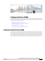
CHAPTER 5
Configuring Private VLANs 37
Information About Private VLANs 37
Primary and Secondary VLANs in Private VLANs 38
Private VLAN Ports 38
Primary, Isolated, and Community Private VLANs 39
Associating Primary and Secondary VLANs 40
Private VLAN Promiscuous Trunks 41
Private VLAN Isolated Trunks 41
Broadcast Traffic in Private VLANs 41
Private VLAN Port Isolation 41
Guidelines and Limitations for Private VLANs 42
Configuring a Private VLAN 42
Enabling Private VLANs 42
Configuring a VLAN as a Private VLAN 43
Associating Secondary VLANs with a Primary Private VLAN 43
Configuring an Interface as a Private VLAN Host Port 45
Configuring an Interface as a Private VLAN Promiscuous Port 45
Configuring a Promiscuous Trunk Port 46
Configuring an Isolated Trunk Port 46
Configuring the Allowed VLANs for PVLAN Trunking Ports 46
Configuring Native 802.1Q VLANs on Private VLANs 47
Verifying the Private VLAN Configuration 47
CHAPTER 6
Configuring Access and Trunk Interfaces 49
Information About Access and Trunk Interfaces 49
Understanding Access and Trunk Interfaces 49
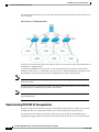
Understanding IEEE 802.1Q Encapsulation 50
Understanding Access VLANs 51
Understanding the Native VLAN ID for Trunk Ports 52
Understanding Allowed VLANs 52
Understanding Native 802.1Q VLANs 52
Cisco Nexus 3000 NX-OS Layer 2 Switching Configuration Guide, Release 5.0(3)U3(1)
OL-26590-01
v
Contents
Configuring Access and Trunk Interfaces 53
Configuring a LAN Interface as an Ethernet Access Port 53
Configuring Access Host Ports 54
Configuring Trunk Ports 54
Configuring the Native VLAN for 802.1Q Trunking Ports 55
Configuring the Allowed VLANs for Trunking Ports 55
Configuring Native 802.1Q VLANs 56
Verifying Interface Configuration 57
CHAPTER 7
Configuring Switching Modes 59
Information About Switching Modes 59
Guidelines and Limitations for Switching Modes 60
Licensing Requirements for Switching Modes 60
Default Settings for Switching Modes 61
Configuring Switching Modes 61
Enabling Store-and-Forward Switching 61
Reenabling Cut-Through Switching 61
Feature History for Switching Modes 62
CHAPTER 8
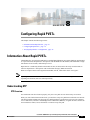
Configuring Rapid PVST+ 63
Information About Rapid PVST+ 63
Understanding STP 63
STP Overview 63
Understanding How a Topology is Created 64
Understanding the Bridge ID 64
Bridge Priority Value 64
Extended System ID 65
STP MAC Address Allocation 65
Understanding BPDUs 66
Election of the Root Bridge 67
Creating the Spanning Tree Topology 67
Understanding Rapid PVST+ 68
Rapid PVST+ Overview 68
Rapid PVST+ BPDUs 69
Proposal and Agreement Handshake 70
Cisco Nexus 3000 NX-OS Layer 2 Switching Configuration Guide, Release 5.0(3)U3(1)
vi
OL-26590-01
Contents
Protocol Timers 71
Port Roles 71
Port States 72
Rapid PVST+ Port State Overview 72
Blocking State 73
Learning State 73
Forwarding State 73
Disabled State 74
Summary of Port States 74
Synchronization of Port Roles 74
Processing Superior BPDU Information 75
Processing Inferior BPDU Information 76
Spanning-Tree Dispute Mechanism 76
Port Cost 76
Port Priority 77
Rapid PVST+ and IEEE 802.1Q Trunks 77
Rapid PVST+ Interoperation with Legacy 802.1D STP 77
Rapid PVST+ Interoperation with 802.1s MST 78
Configuring Rapid PVST+ 78
Enabling Rapid PVST+ 78
Enabling Rapid PVST+ per VLAN 79
Configuring the Root Bridge ID 80
Configuring a Secondary Root Bridge 81
Configuring the Rapid PVST+ Port Priority 82
Configuring the Rapid PVST+ Pathcost Method and Port Cost 83
Configuring the Rapid PVST+ Bridge Priority of a VLAN 83
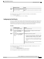
Configuring the Rapid PVST+ Hello Time for a VLAN 84
Configuring the Rapid PVST+ Forward Delay Time for a VLAN 85
Configuring the Rapid PVST+ Maximum Age Time for a VLAN 85
Specifying the Link Type 85
Restarting the Protocol 86
Verifying Rapid PVST+ Configurations 86
CHAPTER 9
Configuring Multiple Spanning Tree 89
Information About MST 89
Cisco Nexus 3000 NX-OS Layer 2 Switching Configuration Guide, Release 5.0(3)U3(1)
OL-26590-01
vii
Contents
MST Overview 89
MST Regions 90
MST BPDUs 90
MST Configuration Information 91
IST, CIST, and CST 91
IST, CIST, and CST Overview 91
Spanning Tree Operation Within an MST Region 92
Spanning Tree Operations Between MST Regions 92
MST Terminology 93
Hop Count 94
Boundary Ports 94
Spanning-Tree Dispute Mechanism 95
Port Cost and Port Priority 96
Interoperability with IEEE 802.1D 96
Interoperability with Rapid PVST+: Understanding PVST Simulation 97
Configuring MST 97
MST Configuration Guidelines 97
Enabling MST 97
Entering MST Configuration Mode 98
Specifying the MST Name 99
Specifying the MST Configuration Revision Number 100
Specifying the Configuration on an MST Region 100
Mapping and Unmapping VLANs to MST Instances 102
Mapping Secondary VLANs to Same MSTI as Primary VLANs for Private VLANs 102
Configuring the Root Bridge 103
Configuring a Secondary Root Bridge 104
Configuring the Port Priority 105
Configuring the Port Cost 106
Configuring the Switch Priority 106
Configuring the Hello Time 107
Configuring the Forwarding-Delay Time 108
Configuring the Maximum-Aging Time 108
Configuring the Maximum-Hop Count 109
Configuring PVST Simulation Globally 109
Configuring PVST Simulation Per Port 110
Cisco Nexus 3000 NX-OS Layer 2 Switching Configuration Guide, Release 5.0(3)U3(1)
viii
OL-26590-01
Contents
Specifying the Link Type 111
Restarting the Protocol 111
Verifying MST Configurations 112
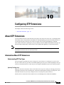
CHAPTER 10
Configuring STP Extensions 113
About STP Extensions 113
Information About STP Extensions 113
Understanding STP Port Types 113
Spanning Tree Edge Ports 113
Spanning Tree Network Ports 114
Spanning Tree Normal Ports 114
Understanding Bridge Assurance 114
Understanding BPDU Guard 114
Understanding BPDU Filtering 115
Understanding Loop Guard 116
Understanding Root Guard 116
Configuring STP Extensions 117
STP Extensions Configuration Guidelines 117
Configuring Spanning Tree Port Types Globally 117
Configuring Spanning Tree Edge Ports on Specified Interfaces 118
Configuring Spanning Tree Network Ports on Specified Interfaces 119
Enabling BPDU Guard Globally 120
Enabling BPDU Guard on Specified Interfaces 121
Enabling BPDU Filtering Globally 122
Enabling BPDU Filtering on Specified Interfaces 123
Enabling Loop Guard Globally 124
Enabling Loop Guard or Root Guard on Specified Interfaces 124
Verifying STP Extension Configuration 125
CHAPTER 11
Configuring LLDP 127
Configuring Global LLDP Commands 127
Configuring Interface LLDP Commands 129
CHAPTER 12
Configuring the MAC Address Table 131
Information About MAC Addresses 131
Cisco Nexus 3000 NX-OS Layer 2 Switching Configuration Guide, Release 5.0(3)U3(1)
OL-26590-01
ix
Contents
Configuring MAC Addresses 131
Configuring a Static MAC Address 131
Configuring the Aging Time for the MAC Table 132
Clearing Dynamic Addresses from the MAC Table 133
Verifying the MAC Address Configuration 133
CHAPTER 13
Configuring IGMP Snooping 135
Information About IGMP Snooping 135
IGMPv1 and IGMPv2 136
IGMPv3 137
IGMP Snooping Querier 137
IGMP Forwarding 137
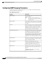
Configuring IGMP Snooping Parameters 138
Verifying IGMP Snooping Configuration 141
CHAPTER 14
Configuring Traffic Storm Control 143
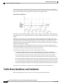
Information About Traffic Storm Control 143
Traffic Storm Guidelines and Limitations 144
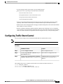
Configuring Traffic Storm Control 145
Verifying Traffic Storm Control Configuration 146
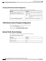
Traffic Storm Control Example Configuration 146
Default Traffic Storm Settings 146
Cisco Nexus 3000 NX-OS Layer 2 Switching Configuration Guide, Release 5.0(3)U3(1)
x
OL-26590-01
Preface
This preface contains the following sections:
• Audience, page xi
• Document Conventions, page xi
• Related Documentation for Nexus 3000 Series NX-OS Software, page xii
• Obtaining Documentation and Submitting a Service Request, page xiv
Audience
This publication is for experienced network administrators who configure and maintain Cisco Nexus Series
devices.
Document Conventions
Command descriptions use the following conventions:
Convention
Description
bold
Bold text indicates the commands and keywords that you enter literally
as shown.
Italic
Italic text indicates arguments for which the user supplies the values.
[x]
Square brackets enclose an optional element(keyword or argument).
[x | y]
Square brackets enclosing keywords or arguments separated by a vertical
bar indicate an optional choice.
{x | y}
Braces enclosing keywords or arguments separated by a vertical bar
indicate a required choice.
Cisco Nexus 3000 NX-OS Layer 2 Switching Configuration Guide, Release 5.0(3)U3(1)
OL-26590-01
xi
Preface
Related Documentation for Nexus 3000 Series NX-OS Software
Convention
Description
[x {y | z}]
Nested set of square brackets or braces indicate optional or required
choices within optional or required elements. Braces and a vertical bar
within square brackets indicate a required choice within an optional
element.
variable
Indicates a variable for which you supply values, in context where italics
cannot be used.
string
A nonquoted set of characters. Do not use quotation marks around the
string or the string will include the quotation marks.
Examples use the following conventions:
Convention
Description
screen font
Terminal sessions and information the switch displays are in screen font.
boldface screen font
Information you must enter is in boldface screen font.
italic screen font
Arguments for which you supply values are in italic screen font.
<>
Nonprinting characters, such as passwords, are in angle brackets.
[]
Default responses to system prompts are in square brackets.
!, #
An exclamation point (!) or a pound sign (#) at the beginning of a line
of code indicates a comment line.
This document uses the following conventions:
Note
Caution
Means reader take note. Notes contain helpful suggestions or references to material not covered in the
manual.
Means reader be careful. In this situation, you might do something that could result in equipment damage
or loss of data.
Related Documentation for Nexus 3000 Series NX-OS Software
The entire Cisco NX-OS 3000 Series documentation set is available at the following URL:
http://www.cisco.com/en/US/products/ps11541/tsd_products_support_series_home.html
Cisco Nexus 3000 NX-OS Layer 2 Switching Configuration Guide, Release 5.0(3)U3(1)
xii
OL-26590-01
Preface
Related Documentation for Nexus 3000 Series NX-OS Software
Release Notes
The release notes are available at the following URL:
http://www.cisco.com/en/US/products/ps11541/prod_release_notes_list.html
Installation and Upgrade Guides
The installation and upgrade guides are available at the following URL:
http://www.cisco.com/en/US/products/ps11541/prod_installation_guides_list.html
The documents in this category include:
• Cisco Nexus 5000 Series, Cisco Nexus 3000 Series, and Cisco Nexus 2000 Series Safety Information
and Documentation
• Regulatory, Compliance, and Safety Information for the Cisco Nexus 5000 Series, Cisco Nexus 3000
Series, and Cisco Nexus 2000 Series
• Cisco Nexus 3000 Series Hardware Installation Guide
Configuration Guides
The configuration guides are available at the following URL:
http://www.cisco.com/en/US/products/ps11541/products_installation_and_configuration_guides_list.html
The documents in this category include:
• Configuration Limits for Cisco NX-OS
• Fundamentals Configuration Guide
• Layer 2 Switching Configuration Guide
• Multicast Configuration Guide
• Quality of Service Configuration Guide
• Security Configuration Guide
• System Management Configuration Guide
• Unicast Routing Configuration Guide
• Verified Scalability Guide for Cisco NX-OS
Technical References
The technical references are available at the following URL:
http://www.cisco.com/en/US/products/ps11541/prod_technical_reference_list.html
Error and System Messages
The error and system message reference guides are available at the following URL:
http://www.cisco.com/en/US/products/ps11541/products_system_message_guides_list.html
Cisco Nexus 3000 NX-OS Layer 2 Switching Configuration Guide, Release 5.0(3)U3(1)
OL-26590-01
xiii
Preface
Obtaining Documentation and Submitting a Service Request
Obtaining Documentation and Submitting a Service Request
For information on obtaining documentation, submitting a service request, and gathering additional information,
see the monthly What's New in Cisco Product Documentation, which also lists all new and revised Cisco
technical documentation, at:
http://www.cisco.com/en/US/docs/general/whatsnew/whatsnew.html
Subscribe to the What's New in Cisco Product Documentation as a Really Simple Syndication (RSS) feed
and set content to be delivered directly to your desktop using a reader application. The RSS feeds are a free
service and Cisco currently supports RSS version 2.0.
Cisco Nexus 3000 NX-OS Layer 2 Switching Configuration Guide, Release 5.0(3)U3(1)
xiv
OL-26590-01
CHAPTER
1
New and Changed Information for this Release
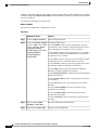
The following table provides an overview of the significant changes to this guide for this current release.
The table does not provide an exhaustive list of all changes made to the configuration guides or of the new
features in this release.
• New and Changed Information for this Release, page 1
New and Changed Information for this Release
The following table provides an overview of the significant changes to this guide for this current release. The
table does not provide an exhaustive list of all changes made to the configuration guides or of the new features
in this release.
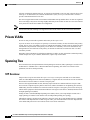
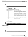
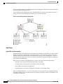
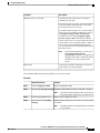
Table 1: New and Changed Features
Feature
Description
Added or
Changed
in
Release
Where Documented
Switching Modes
Added a new chapter about configuring your
switching mode. There are two switching
modes: cut-through and store-and-forward.
5.0(3)U3(1) Configuring Switching
Modes, on page 59
Cisco Nexus 3000 NX-OS Layer 2 Switching Configuration Guide, Release 5.0(3)U3(1)
OL-26590-01
1
New and Changed Information for this Release
New and Changed Information for this Release
Cisco Nexus 3000 NX-OS Layer 2 Switching Configuration Guide, Release 5.0(3)U3(1)
2
OL-26590-01
CHAPTER
2
Overview
This chapter contains the following sections:
• Layer 2 Ethernet Switching Overview, page 3
• VLANs, page 3
• Private VLANs, page 4
• Spanning Tree , page 4
Layer 2 Ethernet Switching Overview
The device supports simultaneous, parallel connections between Layer 2 Ethernet segments. Switched
connections between Ethernet segments last only for the duration of the packet. New connections can be made
between different segments for the next packet.
The device solves congestion problems caused by high-bandwidth devices and a large number of users by
assigning each device (for example, a server) to its own 10-, 100-, 1000-Mbps, or 10-Gigabit collision domain.
Because each LAN port connects to a separate Ethernet collision domain, servers in a switched environment
achieve full access to the bandwidth.
Because collisions cause significant congestion in Ethernet networks, an effective solution is full-duplex
communication. Typically, 10/100-Mbps Ethernet operates in half-duplex mode, which means that stations
can either receive or transmit. In full-duplex mode, which is configurable on these interfaces, two stations
can transmit and receive at the same time. When packets can flow in both directions simultaneously, the
effective Ethernet bandwidth doubles. 1/10-Gigabit Ethernet operates in full-duplex only.
VLANs
A VLAN is a switched network that is logically segmented by function, project team, or application, without
regard to the physical locations of the users. VLANs have the same attributes as physical LANs, but you can
group end stations even if they are not physically located on the same LAN segment.
Any switch port can belong to a VLAN, and unicast, broadcast, and multicast packets are forwarded and
flooded only to end stations in that VLAN. Each VLAN is considered as a logical network, and packets
destined for stations that do not belong to the VLAN must be forwarded through a bridge or a router.
Cisco Nexus 3000 NX-OS Layer 2 Switching Configuration Guide, Release 5.0(3)U3(1)
OL-26590-01
3
Overview
Private VLANs
All ports, including the management port, are assigned to the default VLAN (VLAN1) when the device first
comes up. A VLAN interface, or switched virtual interface (SVI), is a Layer 3 interface that is created to
provide communication between VLANs.
The devices support 4094 VLANs in accordance with the IEEE 802.1Q standard. These VLANs are organized
into several ranges, and you use each range slightly differently. Some of these VLANs are reserved for internal
use by the device and are not available for configuration.
Note
Inter-Switch Link (ISL) trunking is not supported on the NX-OS software for the Cisco Nexus 3000 Series.
Private VLANs
Private VLANs provide traffic separation and security at the Layer 2 level.
A private VLAN is one or more pairs of a primary VLAN and a secondary VLAN, all with the same primary
VLAN. The two types of secondary VLANs are isolated and community VLANs. Hosts on isolated VLANs
communicate only with hosts in the primary VLAN. Hosts in a community VLAN can communicate only
among themselves and with hosts in the primary VLAN but not with hosts in isolated VLANs or in other
community VLANs.
Regardless of the combination of isolated and community secondary VLANs, all interfaces within the primary
VLAN comprise one Layer 2 domain, and therefore, require only one IP subnet.
Spanning Tree
This section discusses the implementation of the Spanning Tree Protocol (STP). Spanning tree is used to refer
to IEEE 802.1w and IEEE 802.1s. When the IEEE 802.1D Spanning Tree Protocol is referred to in the
publication, 802.1D is stated specifically.
STP Overview
STP provides a loop-free network at the Layer 2 level. Layer 2 LAN ports send and receive STP frames,
which are called Bridge Protocol Data Units (BPDUs), at regular intervals. Network devices do not forward
these frames but use the frames to construct a loop-free path.
802.1D is the original standard for STP, and many improvements have enhanced the basic loop-free STP.
You can create a separate loop-free path for each VLAN, which is named Per VLAN Spanning Tree (PVST+).
Additionally, the entire standard was reworked to make the loop-free convergence process faster to keep up
with the faster equipment. This STP standard with faster convergence is the 802.1w standard, which is known
as Rapid Spanning Tree (RSTP).
Finally, the 802.1s standard, Multiple Spanning Trees (MST), allows you to map multiple VLANs into a
single spanning tree instance. Each instance runs an independent spanning tree topology.
Although the software can interoperate with legacy 802.1D systems, the system runs Rapid PVST+ and MST.
You can use either Rapid PVST+ or MST in a given VDC; you cannot mix both in one VDC. Rapid PVST+
is the default STP protocol for Cisco NX-OS for the Cisco Nexus 3000 Series.
Cisco Nexus 3000 NX-OS Layer 2 Switching Configuration Guide, Release 5.0(3)U3(1)
4
OL-26590-01
Overview
Rapid PVST+
Note
Cisco NX-OS for the Cisco Nexus 3000 Series uses the extended system ID and MAC address reduction;
you cannot disable these features.
In addition, Cisco has created some proprietary features to enhance the spanning tree activities.
Rapid PVST+
Rapid PVST+ is the default spanning tree mode for the software and is enabled by default on the default
VLAN and all newly created VLANs.
A single instance, or topology, of RSTP runs on each configured VLAN, and each Rapid PVST+ instance on
a VLAN has a single root device. You can enable and disable STP on a per-VLAN basis when you are running
Rapid PVST+.
MST
The software also supports MST. The multiple independent spanning tree topologies enabled by MST provide
multiple forwarding paths for data traffic, enable load balancing, and reduce the number of STP instances
required to support a large number of VLANs.
MST incorporates RSTP, so it also allows rapid convergence. MST improves the fault tolerance of the network
because a failure in one instance (forwarding path) does not affect other instances (forwarding paths).
Note
Changing the spanning tree mode disrupts the traffic because all spanning tree instances are stopped for
the previous mode and started for the new mode.
You can force specified interfaces to send prestandard, rather than standard, MST messages using the
command-line interface.
STP Extensions
The software supports the following Cisco proprietary features:
• Spanning tree port types—The default spanning tree port type is normal. You can configure interfaces
connected to Layer 2 hosts as edge ports and interfaces connected to Layer 2 switches or bridges as
network ports.
• Bridge Assurance—Once you configure a port as a network port, Bridge Assurance sends BPDUs on
all ports and moves a port into the blocking state if it no longer receives BPDUs. This enhancement is
available only when you are running Rapid PVST+ or MST.
• BPDU Guard—BPDU Guard shuts down the port if that port receives a BPDU.
• BPDU Filter—BPDU Filter suppresses sending and receiving BPDUs on the port.
• Loop Guard—Loop Guard prevents the nondesignated ports from transitioning to the STP forwarding
state, which prevents loops in the network.
Cisco Nexus 3000 NX-OS Layer 2 Switching Configuration Guide, Release 5.0(3)U3(1)
OL-26590-01
5
Overview
STP Extensions
• Root Guard—Root Guard prevents the port from becoming the root in an STP topology.
Cisco Nexus 3000 NX-OS Layer 2 Switching Configuration Guide, Release 5.0(3)U3(1)
6
OL-26590-01
CHAPTER
3
Configuring Ethernet Interfaces
This chapter contains the following sections:
• Information About Ethernet Interfaces, page 7
• Configuring Ethernet Interfaces, page 11
• Displaying Interface Information, page 21
• Displaying Input Packet Discard Information, page 23
• Default Physical Ethernet Settings , page 24
Information About Ethernet Interfaces
The Ethernet ports can operate as standard Ethernet interfaces connected to servers or to a LAN.
On a Cisco Nexus 3000 Series switch, the Ethernet interfaces are enabled by default.
About the Interface Command
You can enable the various capabilities of the Ethernet interfaces on a per-interface basis using the interface
command. When you enter the interface command, you specify the following information:
• Interface type—All physical Ethernet interfaces use the ethernet keyword.
• Slot number
◦Slot 1 includes all the fixed ports.
◦Slot 2 includes the ports on the upper expansion module (if populated).
◦Slot 3 includes the ports on the lower expansion module (if populated).
• Port number
◦Port number within the group.
Cisco Nexus 3000 NX-OS Layer 2 Switching Configuration Guide, Release 5.0(3)U3(1)
OL-26590-01
7
Configuring Ethernet Interfaces
About the Unidirectional Link Detection Parameter
The interface numbering convention is extended to support use with a Cisco Nexus 2000 Series Fabric Extender
as follows:
switch(config)# interface ethernet [chassis/]slot/port
• Chassis ID is an optional entry to address the ports of a connected Fabric Extender. The chassis ID is
configured on a physical Ethernet or EtherChannel interface on the switch to identify the Fabric Extender
discovered via the interface. The chassis ID ranges from 100 to 199.
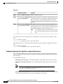
About the Unidirectional Link Detection Parameter
The Cisco-proprietary Unidirectional Link Detection (UDLD) protocol allows ports that are connected through
fiber optics or copper (for example, Category 5 cabling) Ethernet cables to monitor the physical configuration
of the cables and detect when a unidirectional link exists. When the switch detects a unidirectional link, UDLD
shuts down the affected LAN port and alerts the user. Unidirectional links can cause a variety of problems,
including spanning tree topology loops.
UDLD is a Layer 2 protocol that works with the Layer 1 protocols to determine the physical status of a link.
At Layer 1, autonegotiation takes care of physical signaling and fault detection. UDLD performs tasks that
autonegotiation cannot perform, such as detecting the identities of neighbors and shutting down misconnected
LAN ports. When you enable both autonegotiation and UDLD, Layer 1 and Layer 2 detections work together
to prevent physical and logical unidirectional connections and the malfunctioning of other protocols.
A unidirectional link occurs whenever traffic transmitted by the local device over a link is received by the
neighbor but traffic transmitted from the neighbor is not received by the local device. If one of the fiber strands
in a pair is disconnected, as long as autonegotiation is active, the link does not stay up. In this case, the logical
link is undetermined, and UDLD does not take any action. If both fibers are working normally at Layer 1,
then UDLD at Layer 2 determines whether those fibers are connected correctly and whether traffic is flowing
bidirectionally between the correct neighbors. This check cannot be performed by autonegotiation, because
autonegotiation operates at Layer 1.
A Cisco Nexus 3000 Series switch periodically transmits UDLD frames to neighbor devices on LAN ports
with UDLD enabled. If the frames are echoed back within a specific time frame and they lack a specific
acknowledgment (echo), the link is flagged as unidirectional and the LAN port is shut down. Devices on both
ends of the link must support UDLD in order for the protocol to successfully identify and disable unidirectional
links.
Note
By default, UDLD is locally disabled on copper LAN ports to avoid sending unnecessary control traffic
on this type of media.
Cisco Nexus 3000 NX-OS Layer 2 Switching Configuration Guide, Release 5.0(3)U3(1)
8
OL-26590-01
Configuring Ethernet Interfaces
About the Unidirectional Link Detection Parameter
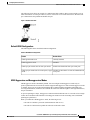
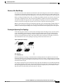
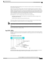
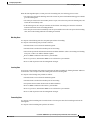
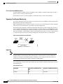
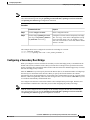
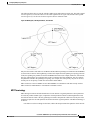
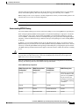
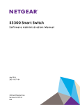
The following figure shows an example of a unidirectional link condition. Device B successfully receives
traffic from Device A on the port. However, Device A does not receive traffic from Device B on the same
port. UDLD detects the problem and disables the port.
Figure 1: Unidirectional Link
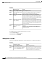
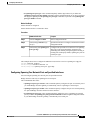
Default UDLD Configuration
The following table shows the default UDLD configuration.
Table 2: UDLD Default Configuration
Feature
Default Value
UDLD global enable state
Globally disabled
UDLD aggressive mode
Disabled
UDLD per-port enable state for fiber-optic media
Enabled on all Ethernet fiber-optic LAN ports
UDLD per-port enable state for twisted-pair (copper) Disabled on all Ethernet 10/100 and 1000BASE-TX
media
LAN ports
UDLD Aggressive and Nonaggressive Modes
UDLD aggressive mode is disabled by default. You can configure UDLD aggressive mode only on
point-to-point links between network devices that support UDLD aggressive mode. If UDLD aggressive mode
is enabled, when a port on a bidirectional link that has a UDLD neighbor relationship established stops
receiving UDLD frames, UDLD tries to reestablish the connection with the neighbor. After eight failed retries,
the port is disabled.
To prevent spanning tree loops, nonaggressive UDLD with the default interval of 15 seconds is fast enough
to shut down a unidirectional link before a blocking port transitions to the forwarding state (with default
spanning tree parameters).
When you enable the UDLD aggressive mode, the following occurs:
• One side of a link has a port stuck (both transmission and receive)
• One side of a link remains up while the other side of the link is down
Cisco Nexus 3000 NX-OS Layer 2 Switching Configuration Guide, Release 5.0(3)U3(1)
OL-26590-01
9
Configuring Ethernet Interfaces
About Interface Speed
In these cases, the UDLD aggressive mode disables one of the ports on the link, which prevents traffic from
being discarded.
About Interface Speed
A Cisco Nexus 3000 Series switch has a number of fixed 10-Gigabit ports, each equipped with SFP+ interface
adapters.
About the Cisco Discovery Protocol
The Cisco Discovery Protocol (CDP) is a device discovery protocol that runs over Layer 2 (the data link layer)
on all Cisco-manufactured devices (routers, bridges, access servers, and switches) and allows network
management applications to discover Cisco devices that are neighbors of already known devices. With CDP,
network management applications can learn the device type and the Simple Network Management Protocol
(SNMP) agent address of neighboring devices running lower-layer, transparent protocols. This feature enables
applications to send SNMP queries to neighboring devices.
CDP runs on all media that support Subnetwork Access Protocol (SNAP). Because CDP runs over the data-link
layer only, two systems that support different network-layer protocols can learn about each other.
Each CDP-configured device sends periodic messages to a multicast address, advertising at least one address
at which it can receive SNMP messages. The advertisements also contain time-to-live, or holdtime information,
which is the length of time a receiving device holds CDP information before discarding it. Each device also
listens to the messages sent by other devices to learn about neighboring devices.
The switch supports both CDP Version 1 and Version 2.
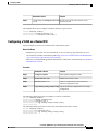
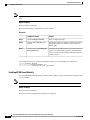
Default CDP Configuration
The following table shows the default CDP configuration.
Table 3: Default CDP Configuration
Feature
Default Setting
CDP interface state
Enabled
CDP timer (packet update frequency)
60 seconds
CDP holdtime (before discarding)
180 seconds
CDP Version-2 advertisements
Enabled
About the Error-Disabled State
An interface is in the error-disabled (err-disabled) state when the inteface is enabled administratively (using
the no shutdown command) but disabled at runtime by any process. For example, if UDLD detects a
unidirectional link, the interface is shut down at runtime. However, because the interface is administratively
Cisco Nexus 3000 NX-OS Layer 2 Switching Configuration Guide, Release 5.0(3)U3(1)
10
OL-26590-01
Configuring Ethernet Interfaces
About Port Profiles
enabled, the interface status displays as err-disabled. Once an interface goes into the err-disabled state, you
must manually reenable it or you can configure an automatic timeout recovery value. The err-disabled detection
is enabled by default for all causes. The automatic recovery is not configured by default.
When an interface is in the err-disabled state, use the errdisable detect cause command to find information
about the error.
You can configure the automatic err-disabled recovery timeout for a particular err-disabled cause by changing
the time variable.
The errdisable recovery cause command provides automatic recovery after 300 seconds. To change the
recovery period, use the errdisable recovery interval command to specify the timeout period. You can specify
30 to 65535 seconds.
If you do not enable the err-disabled recovery for the cause, the interface stays in the err-disabled state until
you enter the shutdown and no shutdown commands. If the recovery is enabled for a cause, the interface is
brought out of the err-disabled state and allowed to retry operation once all the causes have timed out. Use
the show interface status err-disabled command to display the reason behind the error.
About Port Profiles
The Cisco Nexus 3000 Series device does not support Port Profiles.
Guidelines and Limitations for Port Profiles
The Cisco Nexus 3000 Series device does not support Port Profiles.
About the Debounce Timer Parameters
The debounce timer feature is not supported on Nexus 3000.
About MTU Configuration
The Cisco Nexus 3000 Series switch does not fragment frames. As a result, the switch cannot have two ports
in the same Layer 2 domain with different maximum transmission units (MTUs). A per-physical Ethernet
interface MTU is not supported. Instead, the MTU is set according to the QoS classes. You modify the MTU
by setting Class and Policy maps.
Note
When you show the interface settings, a default MTU of 1500 is displayed for physical Ethernet interfaces.
Configuring Ethernet Interfaces
The section includes the following topics:
Cisco Nexus 3000 NX-OS Layer 2 Switching Configuration Guide, Release 5.0(3)U3(1)
OL-26590-01
11
Configuring Ethernet Interfaces
Configuring the UDLD Mode
Configuring the UDLD Mode
You can configure normal or aggressive unidirectional link detection (UDLD) modes for Ethernet interfaces
on devices configured to run UDLD. Before you can enable a UDLD mode for an interface, you must make
sure that UDLD is already enabled on the device that includes the interface. UDLD must also be enabled on
the other linked interface and its device.
To use the normal UDLD mode, you must configure one of the ports for normal mode and configure the other
port for the normal or aggressive mode. To use the aggressive UDLD mode, you must configure both ports
for the aggressive mode.
Note
Before you begin, UDLD must be enabled for the other linked port and its device.
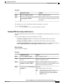
To configure the UDLD mode, perform this task:
Procedure
Command or Action
Purpose
Step 1
switch# configure terminal
Enters configuration mode.
Step 2
switch(config)# feature udld
Enables UDLD for the device.
Step 3
switch(config)# no feature udld
Disables UDLD for the device.
Step 4
switch(config)# show udld global
Displays the UDLD status for the device.
Step 5
switch(config)# interface type slot/port
Specifies an interface to configure, and enters
interface configuration mode.
Step 6
switch(config-if)# udld {enable | disable Enables the normal UDLD mode, disables
UDLD, or enables the aggressive UDLD mode.
| aggressive}
Step 7
switch(config-if)# show udld interface
Displays the UDLD status for the interface.
This example shows how to enable the UDLD for the switch:
switch# configure terminal
switch(config)# feature udld
This example shows how to enable the normal UDLD mode for an Ethernet port:
switch# configure terminal
switch(config)# interface ethernet 1/4
switch(config-if)# udld enable
This example shows how to enable the aggressive UDLD mode for an Ethernet port:
switch# configure terminal
switch(config)# interface ethernet 1/4
switch(config-if)# udld aggressive
Cisco Nexus 3000 NX-OS Layer 2 Switching Configuration Guide, Release 5.0(3)U3(1)
12
OL-26590-01
Configuring Ethernet Interfaces
Changing an Interface Port Mode
This example shows how to disable UDLD for an Ethernet port:
switch# configure terminal
switch(config)# interface ethernet 1/4
switch(config-if)# udld disable
This example shows how to disable UDLD for the switch:
switch# configure terminal
switch(config)# no feature udld
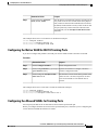
Changing an Interface Port Mode
You can configure a Quad small form-factor pluggable (QSFP+) port by using the hardware profile portmode
command. To restore the defaults, use the no form of this command.
To change an interface port mode, preform this task:
Procedure
Command or Action
Purpose
Step 1
switch# configure terminal
Enters global configuration mode.
Step 2
switch(config)# copy
running-config bootflash:
my-config.cfg
Copies the running configuration to the bootflash. You
can use this file to configure your device later.
Step 3
switch(config)# write erase
Removes all the interface configurations.
Step 4
switch(config)# reload
Reloads the Cisco Nexus 3000 Series switch software.
Step 5
switch(config)# [no] hardware
profile portmode portmode
Changes the interface port mode.
Step 6
switch(config)# copy
running-config startup-config
(Optional)
Saves the change persistently through reboots and restarts
by copying the running configuration to the startup
configuration.
Step 7
switch(config)# reload
Reloads the Cisco Nexus 3000 Series switch software.
Manually apply all the interface configuration. You can
refer to the configuration file that you saved earlier.
Note
The interface numbering changes if the ports
are changed from 40G mode to 4x10G mode or
vice-versa.
This example shows how to change the port mode to 48x10g+4x40g for QSFP+ ports:
switch# configure terminal
switch(config) copy running-config bootflash:my-config.cfg
switch(config)# write erase
switch(config)# reload
WARNING: This command will reboot the system
Do you want to continue? (y/n) [n] y
Cisco Nexus 3000 NX-OS Layer 2 Switching Configuration Guide, Release 5.0(3)U3(1)
OL-26590-01
13
Configuring Ethernet Interfaces
Configuring Interface Speed
switch(config)# hardware profile portmode 48x10g+4x40g
Warning: This command will take effect only after saving the configuration and reload!
Port configurations could get lost when port mode is changed!
switch(config)# copy running-config startup-config
switch(config)# reload
WARNING: This command will reboot the system
Do you want to continue? (y/n) [n] y
This example shows how to change the port mode to 48x10g+4x40g for QSFP+ ports and verify the changes:
switch# configure terminal
switch(config)# hardware profile portmode 48x10g+4x40g
Warning: This command will take effect only after saving the configuration and r
eload! Port configurations could get lost when port mode is changed!
switch(config)# show running-config
!Command: show running-config
!Time: Thu Aug 25 07:39:37 2011
version 5.0(3)U2(1)
feature telnet
no feature ssh
feature lldp
username admin password 5 $1$OOV4MdOM$BAB5RkD22YanT4empqqSM0 role network-admin
ip domain-lookup
switchname BLR-QG-5
ip access-list my-acl
10 deny ip any 10.0.0.1/32
20 deny ip 10.1.1.1/32 any
class-map type control-plane match-any copp-arp
class-map type control-plane match-any copp-bpdu
:
:
control-plane
service-policy input copp-system-policy
hardware profile tcam region arpacl 128
hardware profile tcam region ifacl 256
hardware profile tcam region racl 256
hardware profile tcam region vacl 512
hardware profile portmode 48x10G+4x40G
snmp-server user admin network-admin auth md5 0xdd1d21ee42e93106836cdefd1a60e062
<--Output truncated-->
switch#
This example shows how to restore the default port mode for QSFP+ ports:
switch# configure terminal
switch(config)# no hardware profile portmode
Warning: This command will take effect only after saving the configuration and r
eload! Port configurations could get lost when port mode is changed!
switch(config)#
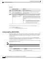
Configuring Interface Speed
Procedure
Command or Action
Purpose
Step 1
switch# configure terminal
Enters configuration mode.
Step 2
switch(config)# interface type
slot/port
Enters interface configuration mode for the specified
interface. This interface must have a 1-Gigabit Ethernet SFP
transceiver inserted into it.
Step 3
switch(config-if)# speed speed
Sets the speed on the interface.
Cisco Nexus 3000 NX-OS Layer 2 Switching Configuration Guide, Release 5.0(3)U3(1)
14
OL-26590-01
Configuring Ethernet Interfaces
Disabling Link Negotiation
Command or Action
Purpose
This command can only be applied to a physical Ethernet
interface. The speed argument can be set to one of the
following:
• 10 Mbps
• 100 Mbps
• 1 Gbps
• 10Gbps
• automatic
The following example shows how to set the speed for a 1-Gigabit Ethernet port:
switch# configure terminal
switch(config)# interface ethernet 1/4
switch(config-if)# speed 1000
Note
If the interface and transceiver speed is mismatched, the SFP validation failed message is displayed when
you enter the show interface ethernet slot/port command. For example, if you insert a 1-Gigabit SFP
transceiver into a port without configuring the speed 1000 command, you will get this error. By default,
all ports are 10 Gigabits.
Disabling Link Negotiation
You can disable link negotiation using the no negotiate auto command. By default, auto-negotiation is enabled
on 1-Gigabit ports and disabled on 10-Gigabit ports. By default, auto-negotiation is enabled on the Cisco
Nexus 3064 and 3064-X switches and disabled on the Cisco Nexus 3048 switch.
This command is equivalent to the IOS speed non-negotiate command.
Note
Cisco does not recommend that you to enable auto negotiation on 10-Gigabit ports. Enabling
auto-negotiation on 10-Gigabit ports brings the link down. By default, link negotiation is disabled on
10-Gigabit ports.
Procedure
Command or Action
Purpose
Step 1
switch# configure terminal
Enters configuration mode.
Step 2
switch(config)# interface ethernet
slot/port
Selects the interface and enters interface mode.
Cisco Nexus 3000 NX-OS Layer 2 Switching Configuration Guide, Release 5.0(3)U3(1)
OL-26590-01
15
Configuring Ethernet Interfaces
Configuring the CDP Characteristics
Command or Action
Purpose
Step 3
switch(config-if)# no negotiate auto
Disables link negotiation on the selected Ethernet
interface (1-Gigabit port).
Step 4
switch(config-if)# negotiate auto
(Optional)
Enables link negotiation on the selected Ethernet
interface. The default for 1-Gigabit ports is enabled.
This example shows how to disable auto negotiation on a specified Ethernet interface (1-Gigabit port):
switch# configure terminal
switch(config)# interface ethernet 1/1
switch(config-if)# no negotiate auto
switch(config-if)#
This example shows how to enable auto negotiation on a specified Ethernet interface (1-Gigabit port):
switch# configure terminal
switch(config)# interface ethernet 1/5
switch(config-if)# negotiate auto
switch(config-if)#
Configuring the CDP Characteristics
You can configure the frequency of Cisco Discovery Protocol (CDP) updates, the amount of time to hold the
information before discarding it, and whether or not to send Version-2 advertisements.
To configure CDP characteristics for an interface, perform this task:
Procedure
Command or Action
Purpose
Step 1
switch# configure terminal
Enters configuration mode.
Step 2
switch(config)# [no] cdp
advertise {v1 | v2 }
(Optional)
Configures the version to use to send CDP advertisements.
Version-2 is the default state.
Use the no form of the command to return to its default
setting.
Step 3
switch(config)# [no] cdp format (Optional)
Configures the format of the CDP device ID. The default is
device-id {mac-address |
serial-number | system-name} the system name, which can be expressed as a fully qualified
domain name.
Use the no form of the command to return to its default
setting.
Step 4
switch(config)# [no] cdp
holdtime seconds
(Optional)
Specifies the amount of time a receiving device should hold
the information sent by your device before discarding it. The
range is 10 to 255 seconds; the default is 180 seconds.
Cisco Nexus 3000 NX-OS Layer 2 Switching Configuration Guide, Release 5.0(3)U3(1)
16
OL-26590-01
Configuring Ethernet Interfaces
Enabling or Disabling CDP
Command or Action
Purpose
Use the no form of the command to return to its default
setting.
Step 5
switch(config)# [no] cdp timer
seconds
(Optional)
Sets the transmission frequency of CDP updates in seconds.
The range is 5 to 254; the default is 60 seconds.
Use the no form of the command to return to its default
setting.
This example shows how to configure CDP characteristics:
switch# configure terminal
switch(config)# cdp timer 50
switch(config)# cdp holdtime 120
switch(config)# cdp advertise v2
Enabling or Disabling CDP
You can enable or disable CDP for Ethernet interfaces. This protocol works only when you have it enabled
on both interfaces on the same link.
To enable or disable CDP for an interface, perform this task:
Procedure
Command or Action
Purpose
Step 1
switch# configure terminal
Enters configuration mode.
Step 2
switch(config)# interface type slot/port Enters interface configuration mode for the specified
interface.
Step 3
switch(config-if)# cdp enable
Enables CDP for the interface.
To work correctly, this parameter must be enabled
for both interfaces on the same link.
Step 4
switch(config-if)# no cdp enable
Disables CDP for the interface.
The following example shows how to enable CDP for an Ethernet port:
switch# configure terminal
switch(config)# interface ethernet 1/4
switch(config-if)# cdp enable
This command can only be applied to a physical Ethernet interface.
Cisco Nexus 3000 NX-OS Layer 2 Switching Configuration Guide, Release 5.0(3)U3(1)
OL-26590-01
17
Configuring Ethernet Interfaces
Enabling the Error-Disabled Detection
Enabling the Error-Disabled Detection
You can enable error-disable (err-disabled) detection in an application. As a result, when a cause is detected
on an interface, the interface is placed in an err-disabled state, which is an operational state that is similar to
the link-down state.
Procedure
Step 1
Command or Action
Purpose
config t
Enters configuration mode.
Example:
switch# config t
switch(config)#
Step 2
errdisable detect cause {all | link-flap |
loopback}
Specifies a condition under which to place the
interface in an err-disabled state. The default is
enabled.
Example:
switch(config)# errdisable detect cause
all
switch(config)#
Step 3
shutdown
Example:
Brings the interface down administratively. To
manually recover the interface from the
err-disabled state, enter this command first.
switch(config)# shutdown
switch(config)#
Step 4
no shutdown
Example:
Brings the interface up administratively and
enables the interface to recover manually from
the err-disabled state.
switch(config)# no shutdown
switch(config)#
Step 5
show interface status err-disabled
Displays information about err-disabled
interfaces.
Example:
switch(config)# show interface status
err-disabled
Step 6
copy running-config startup-config
(Optional) Copies the running configuration to
the startup configuration.
Example:
switch(config)# copy running-config
startup-config
This example shows how to enable the err-disabled detection in all cases:
switch(config)#errdisable detect cause all
switch(config)#
Cisco Nexus 3000 NX-OS Layer 2 Switching Configuration Guide, Release 5.0(3)U3(1)
18
OL-26590-01
Configuring Ethernet Interfaces
Enabling the Error-Disabled Recovery
Enabling the Error-Disabled Recovery
You can specify the application to bring the interface out of the error-disabled (err-disabled) state and retry
coming up. It retries after 300 seconds, unless you configure the recovery timer (see the errdisable recovery
interval command).
Procedure
Step 1
Command or Action
Purpose
config t
Enters configuration mode.
Example:
switch#config t
switch(config)#
Step 2
errdisable recovery cause {all | udld |
bpduguard | link-flap | failed-port-state |
pause-rate-limit}
Example:
Specifies a condition under which the interface
automatically recovers from the err-disabled
state, and the device retries bringing the
interface up. The device waits 300 seconds to
retry. The default is disabled.
switch(config)#errdisable recovery cause
all
switch(config-if)#
Step 3
show interface status err-disabled
Displays information about err-disabled
interfaces.
Example:
switch(config)#show interface status
err-disabled
Step 4
copy running-config startup-config
(Optional) Copies the running configuration to
the startup configuration.
Example:
switch(config)#copy running-config
startup-config
This example shows how to enable err-disabled recovery under all conditions:
switch(config)#errdisable recovery cause all
switch(config)#
Configuring the Error-Disabled Recovery Interval
You can use this procedure to configure the err-disabled recovery timer value. The range is from 30 to 65535
seconds. The default is 300 seconds.
Cisco Nexus 3000 NX-OS Layer 2 Switching Configuration Guide, Release 5.0(3)U3(1)
OL-26590-01
19
Configuring Ethernet Interfaces
Configuring the Debounce Timer
Procedure
Step 1
Command or Action
Purpose
config t
Enters configuration mode.
Example:
switch#config t
switch(config)#
Step 2
errdisable recovery interval interval
Example:
switch(config)#errdisable recovery
interval 32
switch(config-if)#
Step 3
show interface status err-disabled
Specifies the interval for the interface to
recover from the err-disabled state. The range
is from 30 to 65535 seconds. The default is
300 seconds.
Displays information about err-disabled
interfaces.
Example:
switch(config)#show interface status
err-disabled
Step 4
copy running-config startup-config
(Optional) Copies the running configuration
to the startup configuration.
Example:
switch(config)#copy running-config
startup-config
This example shows how to enable err-disabled recovery under all conditions:
switch(config)#errdisable recovery cause all
switch(config)#
Configuring the Debounce Timer
This feature is not supported on the Nexus 3000 product.
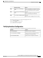
Configuring the Description Parameter
To provide textual interface descriptions for the Ethernet ports, perform this task:
Procedure
Command or Action
Purpose
Step 1
switch# configure terminal
Enters configuration mode.
Step 2
switch(config)# interface type slot/port
Enters interface configuration mode for the
specified interface.
Cisco Nexus 3000 NX-OS Layer 2 Switching Configuration Guide, Release 5.0(3)U3(1)
20
OL-26590-01
Configuring Ethernet Interfaces
Disabling and Restarting Ethernet Interfaces
Step 3
Command or Action
Purpose
switch(config-if)# description test
Specifies the description for the interface.
This example shows how to set the interface description to "Server 3 Interface."
switch# configure terminal
switch(config)# interface ethernet 1/3
switch(config-if)# description Server 3 Interface
Disabling and Restarting Ethernet Interfaces
You can shut down and restart an Ethernet interface. This action disables all of the interface functions and
marks the interface as being down on all monitoring displays. This information is communicated to other
network servers through all dynamic routing protocols. When shut down, the interface is not included in any
routing updates.
To disable an interface, perform this task:
Procedure
Command or Action
Purpose
Step 1
switch# configure terminal
Enters configuration mode.
Step 2
switch(config)# interface type slot/port
Enters interface configuration mode for the
specified interface.
Step 3
switch(config-if)# shutdown
Disables the interface.
Step 4
switch(config-if)# no shutdown
Restarts the interface.
The following example shows how to disable an Ethernet port:
switch# configure terminal
switch(config)# interface ethernet 1/4
switch(config-if)# shutdown
The following example shows how to restart an Ethernet interface:
switch# configure terminal
switch(config)# interface ethernet 1/4
switch(config-if)# no shutdown
Displaying Interface Information
To view configuration information about the defined interfaces, perform one of these tasks:
Cisco Nexus 3000 NX-OS Layer 2 Switching Configuration Guide, Release 5.0(3)U3(1)
OL-26590-01
21
Configuring Ethernet Interfaces
Displaying Interface Information
Command
Purpose
switch# show interface type slot/port
Displays the detailed configuration of the specified
interface.
switch# show interface type slot/port capabilities
Displays detailed information about the capabilities
of the specified interface. This option is only available
for physical interfaces
switch# show interface type slot/port transceiver
Displays detailed information about the transceiver
connected to the specified interface. This option is
only available for physical interfaces.
switch# show interface brief
Displays the status of all interfaces.
switch# show interface flowcontrol
Displays the detailed listing of the flow control
settings on all interfaces.
The show interface command is invoked from EXEC mode and displays the interface configurations. Without
any arguments, this command displays the information for all the configured interfaces in the switch.
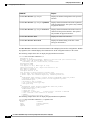
The following example shows how to display the physical Ethernet interface:
switch# show interface ethernet 1/1
Ethernet1/1 is up
Hardware is 1000/10000 Ethernet, address is 000d.eca3.5f08 (bia 000d.eca3.5f08)
MTU 1500 bytes, BW 10000000 Kbit, DLY 10 usec,
reliability 255/255, txload 190/255, rxload 192/255
Encapsulation ARPA
Port mode is trunk
full-duplex, 10 Gb/s, media type is 1/10g
Input flow-control is off, output flow-control is off
Auto-mdix is turned on
Rate mode is dedicated
Switchport monitor is off
Last clearing of "show interface" counters never
5 minute input rate 942201806 bytes/sec, 14721892 packets/sec
5 minute output rate 935840313 bytes/sec, 14622492 packets/sec
Rx
129141483840 input packets 0 unicast packets 129141483847 multicast packets
0 broadcast packets 0 jumbo packets 0 storm suppression packets
8265054965824 bytes
0 No buffer 0 runt 0 Overrun
0 crc 0 Ignored 0 Bad etype drop
0 Bad proto drop
Tx
119038487241 output packets 119038487245 multicast packets
0 broadcast packets 0 jumbo packets
7618463256471 bytes
0 output CRC 0 ecc
0 underrun 0 if down drop
0 output error 0 collision 0 deferred
0 late collision 0 lost carrier 0 no carrier
0 babble
0 Rx pause 8031547972 Tx pause 0 reset
The following example shows how to display the physical Ethernet capabilities:
switch# show interface ethernet 1/1 capabilities
Ethernet1/1
Model:
734510033
Type:
10Gbase-(unknown)
Speed:
1000,10000
Duplex:
full
Cisco Nexus 3000 NX-OS Layer 2 Switching Configuration Guide, Release 5.0(3)U3(1)
22
OL-26590-01
Configuring Ethernet Interfaces
Displaying Input Packet Discard Information
Trunk encap. type:
Channel:
Broadcast suppression:
Flowcontrol:
Rate mode:
QOS scheduling:
CoS rewrite:
ToS rewrite:
SPAN:
UDLD:
802.1Q
yes
percentage(0-100)
rx-(off/on),tx-(off/on)
none
rx-(6q1t),tx-(1p6q0t)
no
no
yes
yes
MDIX:
FEX Fabric:
no
yes
The following example shows how to display the physical Ethernet transceiver:
switch# show interface ethernet 1/1 transceiver
Ethernet1/1
sfp is present
name is CISCO-EXCELIGHT
part number is SPP5101SR-C1
revision is A
serial number is ECL120901AV
nominal bitrate is 10300 MBits/sec
Link length supported for 50/125mm fiber is 82 m(s)
Link length supported for 62.5/125mm fiber is 26 m(s)
cisco id is -cisco extended id number is 4
The following example shows how to display a brief interface status (some of the output has been removed
for brevity):
switch# show interface brief
-------------------------------------------------------------------------------Ethernet
VLAN
Type Mode
Status Reason
Speed
Port
Interface
Ch #
-------------------------------------------------------------------------------Eth1/1
200
eth trunk up
none
10G(D) -Eth1/2
1
eth trunk up
none
10G(D) -Eth1/3
300
eth access down
SFP not inserted
10G(D) -Eth1/4
300
eth access down
SFP not inserted
10G(D) -Eth1/5
300
eth access down
Link not connected
1000(D) -Eth1/6
20
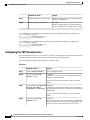
eth access down
Link not connected
10G(D) -Eth1/7
300
eth access down
SFP not inserted
10G(D) -...
The following example shows how to display the CDP neighbors:
switch# show cdp neighbors
Capability Codes: R - Router, T - Trans-Bridge, B - Source-Route-Bridge
S - Switch, H - Host, I - IGMP, r - Repeater,
V - VoIP-Phone, D - Remotely-Managed-Device,
s - Supports-STP-Dispute
Device ID
Local Intrfce
Hldtme Capability Platform
d13-dist-1
mgmt0
148
S I
WS-C2960-24TC
n5k(FLC12080012)
Eth1/5
8
S I s
N5K-C5020P-BA
Port ID
Fas0/9
Eth1/5
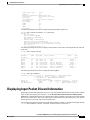
Displaying Input Packet Discard Information
Beginning with Cisco NX-OS Release 5.0(3)U2(1), you can get detailed information on what specific condition
led to an input discard on a given interface. Use the show hardware internal interface indiscard-stats
front-port x command to determine the condition that could be potentially responsible for the input discards
that are seen on port eth1/x. The switch output shows the discards for IPv4, STP, input policy, ACL specific
discard, generic receive drop, and VLAN related discards.
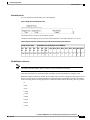
This example shows how to determine the condition that could be potentially responsible for the input discards:
switch# show hardware internal interface indiscard-stats front-port 1
Cisco Nexus 3000 NX-OS Layer 2 Switching Configuration Guide, Release 5.0(3)U3(1)
OL-26590-01
23
Configuring Ethernet Interfaces
Default Physical Ethernet Settings
+-----------------------------------------+-----------------+----------------+
|
Counter Description
|
Count
|
|
+-----------------------------------------+-----------------+----------------+
IPv4 Discards
0
STP Discards
0
Policy Discards
100
ACL Drops
0
Receive Drops
0
Vlan Discards
33
+-----------------------------------------+-----------------+----------------+
Counter Information:
• IPv4 Discards--- IPv4 Discards represent errors at the IP layer, for example the IP checksum error.
• STP Discards--- STP Discards are incremented when the receive interface STP state is not forwarding
the packets received.
• Policy Discards--- Policy Discards are incremented when there are discards because of input policy on
the interface.
• ACL Drops---ACL drops indicate that incoming packets match an ACL entry with a drop action.
• Receive Drops--- This drop increment represents a condition when no output port is determined for an
ingress packet. Receive drops happen because of variety of reasons including IPv4, STP and policy
discards. The drop counter increments in conjunction with one of the above counters or separately.
• Vlan Discard--- Vlan Discard indicates vlan-based discards. For example, a vlan tagged packet ingressing
on a port which is not a member of the vlan.
This example shows how to clear all the input discard counters which is useful for debugging purposes.:
Switch# show hardware internal interface indiscard-stats front-port 1 clear
+-----------------------------------------+-----------------+----------------+-------------------------------------+
|
Counter Description
|
Count
| Last Increment |
Last
Increment Time
|
+-----------------------------------------+-----------------+----------------+-------------------------------------+
Discard Stats have been reset
+-----------------------------------------+-----------------+----------------+-------------------------------------+
Default Physical Ethernet Settings
The following table lists the default settings for all physical Ethernet interfaces:
Parameter
Default Setting
Duplex
Auto (full-duplex)
Encapsulation
ARPA
MTU1
1500 bytes
Port Mode
Access
Speed
Auto (10000)
Cisco Nexus 3000 NX-OS Layer 2 Switching Configuration Guide, Release 5.0(3)U3(1)
24
OL-26590-01
Configuring Ethernet Interfaces
Default Physical Ethernet Settings
1 MTU cannot be changed per-physical Ethernet interface. You modify MTU by selecting maps of QoS classes.
Cisco Nexus 3000 NX-OS Layer 2 Switching Configuration Guide, Release 5.0(3)U3(1)
OL-26590-01
25
Configuring Ethernet Interfaces
Default Physical Ethernet Settings
Cisco Nexus 3000 NX-OS Layer 2 Switching Configuration Guide, Release 5.0(3)U3(1)
26
OL-26590-01
CHAPTER
4
Configuring VLANs
This chapter contains the following sections:
• Information About VLANs, page 27
• Configuring a VLAN, page 30
Information About VLANs
Understanding VLANs
A VLAN is a group of end stations in a switched network that is logically segmented by function or application,
without regard to the physical locations of the users. VLANs have the same attributes as physical LANs, but
you can group end stations even if they are not physically located on the same LAN segment.
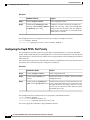
Any switch port can belong to a VLAN, and unicast, broadcast, and multicast packets are forwarded and
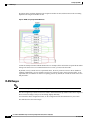
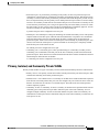
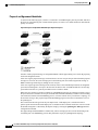
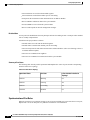
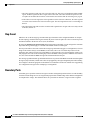
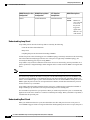
flooded only to end stations in that VLAN. Each VLAN is considered as a logical network, and packets
destined for stations that do not belong to the VLAN must be forwarded through a router. The following figure
shows VLANs as logical networks. The stations in the engineering department are assigned to one VLAN,
Cisco Nexus 3000 NX-OS Layer 2 Switching Configuration Guide, Release 5.0(3)U3(1)
OL-26590-01
27
Configuring VLANs
VLAN Ranges
the stations in the marketing department are assigned to another VLAN, and the stations in the accounting
department are assigned to another VLAN.
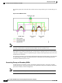
Figure 2: VLANs as Logically Defined Networks
VLANs are usually associated with IP subnetworks. For example, all the end stations in a particular IP subnet
belong to the same VLAN. To communicate between VLANs, you must route the traffic.
By default, a newly created VLAN is operational; that is, the newly created VLAN is in the no shutdown
condition. Additionally, you can configure VLANs to be in the active state, which is passing traffic, or the
suspended state, in which the VLANs are not passing packets. By default, the VLANs are in the active state
and pass traffic.
VLAN Ranges
Note
The extended system ID is always automatically enabled in Cisco NX-OS devices.
The device supports up to 4094 VLANs in accordance with the IEEE 802.1Q standard. The software organizes
these VLANs into ranges, and you use each range slightly differently.
For information about configuration limits, see the configuration limits documentation for your switch.
This table describes the VLAN ranges.
Cisco Nexus 3000 NX-OS Layer 2 Switching Configuration Guide, Release 5.0(3)U3(1)
28
OL-26590-01
Configuring VLANs
Creating, Deleting, and Modifying VLANs
Table 4: VLAN Ranges
VLANs Numbers
Range
Usage
1
Normal
Cisco default. You can use this
VLAN, but you cannot modify or
delete it.
2—1005
Normal
You can create, use, modify, and
delete these VLANs.
1006—3967 and 4048—4093
Extended
You can create, name, and use
these VLANs. You cannot change
the following parameters:
• The state is always active.
• The VLAN is always
enabled. You cannot shut
down these VLANs.
3968-4047 and 4094
Internally allocated
These 80 VLANs and VLAN 4094
are allocated for internal device
use. You cannot create, delete, or
modify any VLANs within the
block reserved for internal use.
The software allocates a group of VLAN numbers for features like multicast and diagnostics, that need to use
internal VLANs for their operation. You cannot use, modify, or delete any of the VLANs in the reserved
group. You can display the VLANs that are allocated internally and their associated use.
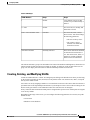
Creating, Deleting, and Modifying VLANs
VLANs are numbered from 1 to 4094. All configured ports belong to the default VLAN when you first bring
up the switch. The default VLAN (VLAN1) uses only default values. You cannot create, delete, or suspend
activity in the default VLAN.
You create a VLAN by assigning a number to it. You can delete VLANs as well as move them from the active
operational state to the suspended operational state. If you attempt to create a VLAN with an existing VLAN
ID, the switch goes into the VLAN submode but does not create the same VLAN again.
Newly created VLANs remain unused until ports are assigned to the specific VLAN. All the ports are assigned
to VLAN1 by default.
Depending on the range of the VLAN, you can configure the following parameters for VLANs (except the
default VLAN):
• VLAN name
• Shutdown or not shutdown
Cisco Nexus 3000 NX-OS Layer 2 Switching Configuration Guide, Release 5.0(3)U3(1)
OL-26590-01
29
Configuring VLANs
About the VLAN Trunking Protocol
When you delete a specified VLAN, the ports associated to that VLAN are shut down and no traffic flows.
However, the system retains all the VLAN-to-port mapping for that VLAN, and when you reenable, or recreate,
the specified VLAN, the system automatically reinstates all the original ports to that VLAN.
Note
Commands entered in the VLAN configuration submode are immediately executed.
VLANs 3968 to 4047 and 4094 are reserved for internal use; these VLANs cannot be changed or used.
About the VLAN Trunking Protocol
VTP is a distributed VLAN database management protocol that synchronizes the VTP VLAN database across
domains. A VTP domain includes one or more network switches that share the same VTP domain name and
that are connected with trunk interfaces. Each device can be in one VTP domain, Layer 2 trunk interfaces,
and Layer 2 port channels.
Guidelines and Limitations for VTP
VTP has the following configuration guidelines and limitations:
• VLAN 1 is required on all trunk ports used for switch interconnects if VTP is supported in the network.
Disabling VLAN 1 from any of these ports prevents VTP from functioning properly.
• If you enable VTP, you must configure either version 1 or version 2.
• The show running-configuration command does not show VLAN or VTP configuration information
for VLANs 1 to 1000.
• VTP pruning is not supported.
• If you are using VTP in a Token Ring environment, you must use version 2.
• You must enter the copy running-config startup-config command followed by a reload after changing
a reserved VLAN range. For example:
switch(config)# system vlan 2000 reserve
This will delete all configs on vlans 2000-2127. Continue anyway? (y/n) [no] y
After the switch reload, VLANs 2000 to 2127 are reserved for internal use, which requires that you enter
the copy running-config startup-config command before the switch reload. Creating VLANs within
this range is not allowed.
• SNMP can perform GET and SET operations on the CISCO-VTP-MIB objects.
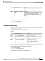
Configuring a VLAN
Creating and Deleting a VLAN
You can create or delete all VLANs except the default VLAN and those VLANs that are internally allocated
for use by the switch. Once a VLAN is created, it is automatically in the active state.
Cisco Nexus 3000 NX-OS Layer 2 Switching Configuration Guide, Release 5.0(3)U3(1)
30
OL-26590-01
Configuring VLANs
Configuring a VLAN
Note
When you delete a VLAN, ports associated to that VLAN shut down. The traffic does not flow and the
packets are dropped.
Procedure
Command or Action
Purpose
Step 1
switch# configure terminal Enters configuration mode.
Step 2
switch(config)# vlan
{vlan-id | vlan-range}
Step 3
Creates a VLAN or a range of VLANs.
If you enter a number that is already assigned to a VLAN, the switch
puts you into the VLAN configuration submode for that VLAN. If
you enter a number that is assigned to an internally allocated VLAN,
the system returns an error message. However, if you enter a range
of VLANs and one or more of the specified VLANs is outside the
range of internally allocated VLANs, the command takes effect on
only those VLANs outside the range. The range is from 2 to 4094;
VLAN1 is the default VLAN and cannot be created or deleted. You
cannot create or delete those VLANs that are reserved for internal
use.
switch(config-vlan)# no
Deletes the specified VLAN or range of VLANs and removes you
vlan {vlan-id | vlan-range} from the VLAN configuration submode. You cannot delete VLAN1
or the internally allocated VLANs.
This example shows how to create a range of VLANs from 15 to 20:
switch# configure terminal
switch(config)# vlan 15-20
Note
You can also create and delete VLANs in the VLAN configuration submode.
Configuring a VLAN
To configure or modify the VLAN for the following parameters, you must be in the VLAN configuration
submode:
• Name
• Shut down
Note
You cannot create, delete, or modify the default VLAN or the internally allocated VLANs. Additionally,
some of these parameters cannot be modified on some VLANs.
Cisco Nexus 3000 NX-OS Layer 2 Switching Configuration Guide, Release 5.0(3)U3(1)
OL-26590-01
31
Configuring VLANs
Adding Ports to a VLAN
Procedure
Command or Action
Purpose
Step 1
switch# configure terminal
Enters configuration mode.
Step 2
switch(config)# vlan {vlan-id Enters VLAN configuration submode. If the VLAN does not
exist, the system first creates the specified VLAN.
| vlan-range}
Step 3
switch(config-vlan)# name
vlan-name
Names the VLAN. You can enter up to 32 alphanumeric
characters to name the VLAN. You cannot change the name of
VLAN1 or the internally allocated VLANs. The default value is
VLANxxxx where xxxx represent four numeric digits (including
leading zeroes) equal to the VLAN ID number.
Step 4
switch(config-vlan)# state
{active | suspend}
Sets the state of the VLAN to active or suspend. While the VLAN
state is suspended, the ports associated with this VLAN are shut
down, and that VLAN does not pass any traffic. The default state
is active. You cannot suspend the state for the default VLAN or
VLANs 1006 to 4094.
Step 5
switch(config-vlan)# no
shutdown
(Optional)
Enables the VLAN. The default value is no shutdown (or
enabled). You cannot shut down the default VLAN, VLAN1, or
VLANs 1006 to 4094.
This example shows how to configure optional parameters for VLAN 5:
switch# configure terminal
switch(config)# vlan 5
switch(config-vlan)# name accounting
switch(config-vlan)# state active
switch(config-vlan)# no shutdown
Adding Ports to a VLAN
After you have completed the configuration of a VLAN, assign ports to it. To add ports, perform this task:
Procedure
Command or Action
Purpose
Step 1
switch# configure terminal
Enters configuration mode.
Step 2
switch(config)# interface {ethernet
slot/port | port-channel number}
Specifies the interface to configure, and enters the
interface configuration mode. The interface can be
a physical Ethernet port or an EtherChannel.
Cisco Nexus 3000 NX-OS Layer 2 Switching Configuration Guide, Release 5.0(3)U3(1)
32
OL-26590-01
Configuring VLANs
Configuring a VLAN as a Routed SVI
Command or Action
Step 3
Purpose
switch(config-if)# switchport access vlan Sets the access mode of the interface to the
specified VLAN.
vlan-id
This example shows how to configure an Ethernet interface to join VLAN 5:
switch# configure terminal
switch(config)# interface ethernet 1/13
switch(config-if)# switchport access vlan 5
Configuring a VLAN as a Routed SVI
You can configure a VLAN to be a routed switch virtual interface (SVI).
Before You Begin
• Install the Layer 3 license. For more information, see License and Copyright Information for Cisco
NX-OS Software available at the following URL: http://www.cisco.com/en/US/docs/switches/datacenter/
sw/4_0/nx-os/license_agreement/nx-ossw_lisns.html.
• Make sure you understand the guidelines and limitations of this feature. For information, see Guidelines
and Limitations for SVIs.
Procedure
Command or Action
Purpose
Step 1
configure terminal
Enters global configuration mode.
Step 2
feature interface-vlan
Enables the creation of SVIs.
Step 3
interface-vlan vlan-id
Creates a VLAN interface (SVI) and enters
interface configuration mode.
Step 4
copy running-config startup-config Copies the running configuration to the startup
configuration.
The following example shows how to configure a VLAN as a routed SVI:
switch# configure terminal
switch(config)# feature interface-vlan
switch(config)# interface vlan 5
switch(config-if)# copy running-config startup-config
switch(config-if)#
The following example shows how to remove the routed SVI function from a VLAN:
switch# configure terminal
switch(config)# no interface vlan 5
switch(config-if)# copy running-config startup-config
switch(config-if)#
Cisco Nexus 3000 NX-OS Layer 2 Switching Configuration Guide, Release 5.0(3)U3(1)
OL-26590-01
33
Configuring VLANs
Configuring a VLAN as a Management SVI
What to Do Next
You can configure routing protocols on this interface.
Configuring a VLAN as a Management SVI
You can configure a VLAN to be a management switch virtual interface (SVI).
Procedure
Command or Action
Purpose
Step 1
configure terminal
Enters global configuration mode.
Step 2
feature interface-vlan
Enables the creation of SVIs.
Step 3
interface-vlan vlan-id management
Creates a VLAN interface (SVI) and configures the
SVI to be used for in-band management.
Step 4
copy running-config startup-config Copies the running configuration to the startup
configuration.
The following example shows how to configure a VLAN as a management SVI:
switch# configure terminal
switch(config)# feature interface-vlan
switch(config)# interface vlan 5
switch(config-if)# management
switch(config-if)# copy running-config startup-config
switch(config-if)#
The following example shows how to remove the management function from an SVI:
switch# configure terminal
switch(config)# interface vlan 5
switch(config-if)# no management
switch(config-if)# copy running-config startup-config
switch(config-if)#
Configuring VTP
You can enable and configure VTP. If you enable VTP, you must configure either version 1 or version 2. If
you are using VTP in a Token Ring environment, you must use version 2.
Procedure
Command or Action
Purpose
Step 1
switch# configure terminal
Enters global configuration mode.
Step 2
switch(config)# feature vtp
Enables VTP on the device. The default is disabled.
Cisco Nexus 3000 NX-OS Layer 2 Switching Configuration Guide, Release 5.0(3)U3(1)
34
OL-26590-01
Configuring VLANs
Configuring VTP
Command or Action
Purpose
Step 3
switch(config)# vtp domain
domain-name
Specifies the name of the VTP domain that you want
this device to join. The default is blank.
Step 4
switch(config)# vtp version {1 | 2} Sets the VTP version that you want to use. The default
is version 1.
Step 5
switch(config)# vtp file file-name
Specifies the ASCII filename of the IFS file system
file where the VTP configuration is stored.
Step 6
switch(config)# vtp password
password-value
Specifies the password for the VTP administrative
domain.
Step 7
switch(config)# exit
Exits the configuration submode.
Step 8
switch# show vtp status
(Optional)
Displays information about the VTP configuration on
the device, such as the version, mode, and revision
number.
Step 9
switch# show vtp counters
(Optional)
Displays information about VTP advertisement
statistics on the device.
Step 10
switch# show vtp interface
(Optional)
Displays the list of VTP-enabled interfaces.
Step 11
switch# show vtp password
(Optional)
Displays the password for the management VTP
domain.
Step 12
switch# copy running-config
startup-config
(Optional)
Copies the running configuration to the startup
configuration.
This example shows how to configure VTP for the device:
switch# configure terminal
switch(config)# feature vtp
switch(config)# vtp domain accounting
switch(config)# vtp version 2
switch(config)# exit
switch#
This example shows the VTP status and that the switch is capable of supporting Version 2 and that the switch
is running Version 1:
switch(config)# show vtp status
VTP Status Information
---------------------VTP Version
Configuration Revision
Maximum VLANs supported locally
Number of existing VLANs
VTP Operating Mode
VTP Domain Name
VTP Pruning Mode
VTP V2 Mode
:
:
:
:
:
:
:
:
2 (capable)
0
1005
502
Transparent
Disabled (Operationally Disabled)
Disabled
Cisco Nexus 3000 NX-OS Layer 2 Switching Configuration Guide, Release 5.0(3)U3(1)
OL-26590-01
35
Configuring VLANs
Verifying VLAN Configuration
VTP Traps Generation
: Disabled
MD5 Digest
: 0xF5 0xF1 0xEC 0xE7 0x29 0x0C 0x2D 0x01
Configuration last modified by 60.10.10.1 at 0-0-00 00:00:00
VTP version running
: 1
Verifying VLAN Configuration
Use one of the following commands to verify the configuration:
Command
Purpose
switch# show running-config vlan [vlan_id | vlan_range]
Displays VLAN information.
switch# show vlan [brief | id [vlan_id | vlan_range] | name name |
summary ]
Displays selected configuration
information for the defined
VLAN(s).
Cisco Nexus 3000 NX-OS Layer 2 Switching Configuration Guide, Release 5.0(3)U3(1)
36
OL-26590-01
CHAPTER
5
Configuring Private VLANs
This chapter contains the following sections:
• Information About Private VLANs, page 37
• Guidelines and Limitations for Private VLANs, page 42
• Configuring a Private VLAN, page 42
• Verifying the Private VLAN Configuration, page 47
Information About Private VLANs
A private VLAN (PVLAN) partitions the Ethernet broadcast domain of a VLAN into subdomains, allowing
you to isolate the ports on the switch from each other. A subdomain consists of a primary VLAN and one or
more secondary VLANs (see the following figure). All VLANs in a PVLAN domain share the same primary
VLAN. The secondary VLAN ID differentiates one subdomain from another. The secondary VLANs may
either be isolated VLANs or community VLANs. A host on an isolated VLAN can only communicate with
Cisco Nexus 3000 NX-OS Layer 2 Switching Configuration Guide, Release 5.0(3)U3(1)
OL-26590-01
37
Configuring Private VLANs
Primary and Secondary VLANs in Private VLANs
the associated promiscuous port in its primary VLAN. Hosts on community VLANs can communicate among
themselves and with their associated promiscuous port but not with ports in other community VLANs.
Figure 3: Private VLAN Domain
Note
You must first create the VLAN before you can convert it to a PVLAN, either primary or secondary.
Primary and Secondary VLANs in Private VLANs
A private VLAN domain has only one primary VLAN. Each port in a private VLAN domain is a member of
the primary VLAN; the primary VLAN is the entire private VLAN domain.
Secondary VLANs provide isolation between ports within the same private VLAN domain. The following
two types are secondary VLANs within a primary VLAN:
• Isolated VLANs—Ports within an isolated VLAN cannot communicate directly with each other at the
Layer 2 level.
• Community VLANs—Ports within a community VLAN can communicate with each other but cannot
communicate with ports in other community VLANs or in any isolated VLANs at the Layer 2 level.
Private VLAN Ports
The three types of PVLAN ports are as follows:
Cisco Nexus 3000 NX-OS Layer 2 Switching Configuration Guide, Release 5.0(3)U3(1)
38
OL-26590-01
Configuring Private VLANs
Primary, Isolated, and Community Private VLANs
• Promiscuous port—A promiscuous port belongs to the primary VLAN. The promiscuous port can
communicate with all interfaces, including the community and isolated host ports, that belong to those
secondary VLANs associated to the promiscuous port and associated with the primary VLAN. You can
have several promiscuous ports in a primary VLAN. Each promiscuous port can have several secondary
VLANs or no secondary VLANs that are associated to that port. You can associate a secondary VLAN
to more than one promiscuous port, as long as the promiscuous port and secondary VLANs are within
the same primary VLAN. You may want to do this for load-balancing or redundancy purposes. You can
also have secondary VLANs that are not associated to any promiscuous port.
A promiscuous port can be configured as an access port.
• Isolated port—An isolated port is a host port that belongs to an isolated secondary VLAN. This port has
complete isolation from other ports within the same PVLAN domain, except that it can communicate
with associated promiscuous ports. PVLANs block all traffic to isolated ports except traffic from
promiscuous ports. Traffic received from an isolated port is forwarded only to promiscuous ports. You
can have more than one isolated port in a specified isolated VLAN. Each port is completely isolated
from all other ports in the isolated VLAN.
An isolated port can be configured an access port.
• Community port—A community port is a host port that belongs to a community secondary VLAN.
Community ports communicate with other ports in the same community VLAN and with associated
promiscuous ports. These interfaces are isolated from all other interfaces in other communities and from
all isolated ports within the PVLAN domain.
A community port must be configured as an access port.
Primary, Isolated, and Community Private VLANs
Primary VLANs and the two types of secondary VLANs (isolated and community) have these characteristics:
• Primary VLAN— The primary VLAN carries traffic from the promiscuous ports to the host ports, both
isolated and community, and to other promiscuous ports.
• Isolated VLAN —An isolated VLAN is a secondary VLAN that carries unidirectional traffic upstream
from the hosts toward the promiscuous ports. You can configure only one isolated VLAN in a PVLAN
domain. An isolated VLAN can have several isolated ports. The traffic from each isolated port also
remains completely separate.
• Community VLAN—A community VLAN is a secondary VLAN that carries upstream traffic from the
community ports to the promiscuous port and to other host ports in the same community. You can
configure multiple community VLANs in a PVLAN domain. The ports within one community can
communicate, but these ports cannot communicate with ports in any other community or isolated VLAN
in the private VLAN.
Cisco Nexus 3000 NX-OS Layer 2 Switching Configuration Guide, Release 5.0(3)U3(1)
OL-26590-01
39
Configuring Private VLANs
Primary, Isolated, and Community Private VLANs
The following figure shows the traffic flows within a PVLAN, along with the types of VLANs and types of
ports.
Figure 4: Private VLAN Traffic Flows
Note
The PVLAN traffic flows are unidirectional from the host ports to the promiscuous ports. Traffic received
on primary VLAN enforces no separation and forwarding is done as in a normal VLAN.
A promiscuous access port can serve only one primary VLAN and multiple secondary VLANs (community
and isolated VLANs). With a promiscuous port, you can connect a wide range of devices as access points to
a PVLAN. For example, you can use a promiscuous port to monitor or back up all the PVLAN servers from
an administration workstation.
In a switched environment, you can assign an individual PVLAN and associated IP subnet to each individual
or common group of end stations. The end stations need to communicate only with a default gateway to
communicate outside the private VLAN.
Associating Primary and Secondary VLANs
To allow host ports in secondary VLANs to communicate outside the PVLAN, you associate secondary
VLANs to the primary VLAN. If the association is not operational, the host ports (community and isolated
ports) in the secondary VLAN are brought down.
Note
You can associate a secondary VLAN with only one primary VLAN.
Cisco Nexus 3000 NX-OS Layer 2 Switching Configuration Guide, Release 5.0(3)U3(1)
40
OL-26590-01
Configuring Private VLANs
Private VLAN Promiscuous Trunks
For an association to be operational, the following conditions must be met:
• The primary VLAN must exist and be configured as a primary VLAN.
• The secondary VLAN must exist and be configured as either an isolated or community VLAN.
Note
Use the show vlan private-vlan command to verify that the association is operational. The switch does
not display an error message when the association is nonoperational.
If you delete either the primary or secondary VLAN, the ports that are associated with the VLAN become
inactive. Use the no private-vlan command to return the VLAN to the normal mode. All primary and secondary
associations on that VLAN are suspended, but the interfaces remain in PVLAN mode. When you convert the
VLAN back to PVLAN mode, the original associations are reinstated.
If you enter the no vlan command for the primary VLAN, all PVLAN associations with that VLAN are
deleted. However, if you enter the no vlan command for a secondary VLAN, the PVLAN associations with
that VLAN are suspended and are restored when you recreate the specified VLAN and configure it as the
previous secondary VLAN.
In order to change the association between a secondary and primary VLAN, you must first remove the current
association and then add the desired association.
Private VLAN Promiscuous Trunks
The Cisco Nexus 3000 Series device does not support Private VLAN trunk ports.
Private VLAN Isolated Trunks
The Cisco Nexus 3000 Series device does not support Private VLAN trunk ports.
Broadcast Traffic in Private VLANs
Broadcast traffic from ports in a private VLAN flows in the following ways:
• The broadcast traffic flows from a promiscuous port to all ports in the primary VLAN (which includes
all the ports in the community and isolated VLANs). This broadcast traffic is distributed to all ports
within the primary VLAN, including those ports that are not configured with private VLAN parameters.
• The broadcast traffic from an isolated port is distributed only to those promiscuous ports in the primary
VLAN that are associated to that isolated port.
• The broadcast traffic from community ports is distributed to all ports within the port’s community and
to all promiscuous ports that are associated to the community port. The broadcast packets are not
distributed to any other communities within the primary VLAN or to any isolated ports.
Private VLAN Port Isolation
You can use PVLANs to control access to end stations as follows:
Cisco Nexus 3000 NX-OS Layer 2 Switching Configuration Guide, Release 5.0(3)U3(1)
OL-26590-01
41
Configuring Private VLANs
Guidelines and Limitations for Private VLANs
• Configure selected interfaces connected to end stations as isolated ports to prevent any communication.
For example, if the end stations are servers, this configuration prevents communication between the
servers.
• Configure interfaces connected to default gateways and selected end stations (for example, backup
servers) as promiscuous ports to allow all end stations access to a default gateway.
Guidelines and Limitations for Private VLANs
When configuring PVLANs, follow these guidelines:
• You must have already created the VLAN before you can assign the specified VLAN as a private VLAN.
• You must enable PVLANs before the switch can apply the PVLAN functionality.
• You cannot disable PVLANs if the switch has any operational ports in a PVLAN mode.
• Enter the private-vlan synchronize command from within the Multiple Spanning Tree (MST) region
definition to map the secondary VLANs to the same MST instance as the primary VLAN.
Configuring a Private VLAN
Enabling Private VLANs
You must enable PVLANs on the switch to use the PVLAN functionality.
Note
The PVLAN commands do not appear until you enable the PVLAN feature.
Procedure
Command or Action
Purpose
Step 1
switch# configure terminal
Enters configuration mode.
Step 2
switch(config)# feature private-vlan Enables the PVLAN feature on the switch.
Step 3
switch(config)# no feature
private-vlan
(Optional)
Disables the PVLAN feature on the switch.
Note
You cannot disable PVLANs if there are
operational ports on the switch that are in
PVLAN mode.
This example shows how to enable the PVLAN feature on the switch:
switch# configure terminal
switch(config)# feature private-vlan
Cisco Nexus 3000 NX-OS Layer 2 Switching Configuration Guide, Release 5.0(3)U3(1)
42
OL-26590-01
Configuring Private VLANs
Configuring a VLAN as a Private VLAN
Configuring a VLAN as a Private VLAN
To create a PVLAN, you first create a VLAN, and then configure that VLAN to be a PVLAN.
Before You Begin
Ensure that the PVLAN feature is enabled.
Procedure
Command or Action
Purpose
Step 1
switch# configure terminal
Enters configuration mode.
Step 2
switch(config)# vlan {vlan-id |
vlan-range}
Places you into the VLAN configuration submode.
Step 3
switch(config-vlan)# private-vlan
{community | isolated | primary}
Configures the VLAN as either a community, isolated,
or primary PVLAN. In a PVLAN, you must have one
primary VLAN. You can have multiple community and
isolated VLANs.
Step 4
switch(config-vlan)# no private-vlan (Optional)
Removes the PVLAN configuration from the specified
{community | isolated | primary}
VLAN(s) and returns it to normal VLAN mode. If you
delete either the primary or secondary VLAN, the ports
that are associated with the VLAN become inactive.
This example shows how to assign VLAN 5 to a PVLAN as the primary VLAN:
switch# configure terminal
switch(config)# vlan 5
switch(config-vlan)# private-vlan primary
This example shows how to assign VLAN 100 to a PVLAN as a community VLAN:
switch# configure terminal
switch(config)# vlan 100
switch(config-vlan)# private-vlan community
This example shows how to assign VLAN 200 to a PVLAN as an insolated VLAN:
switch# configure terminal
switch(config)# vlan 200
switch(config-vlan)# private-vlan isolated
Associating Secondary VLANs with a Primary Private VLAN
When you associate secondary VLANs with a primary VLAN, follow these guidelines:
• The secondary-vlan-list parameter cannot contain spaces. It can contain multiple comma-separated items.
Each item can be a single secondary VLAN ID or a hyphenated range of secondary VLAN IDs.
Cisco Nexus 3000 NX-OS Layer 2 Switching Configuration Guide, Release 5.0(3)U3(1)
OL-26590-01
43
Configuring Private VLANs
Associating Secondary VLANs with a Primary Private VLAN
• The secondary-vlan-list parameter can contain multiple community VLAN IDs and one isolated VLAN
ID.
• Enter a secondary-vlan-list or use the add keyword with a secondary-vlan-list to associate secondary
VLANs with a primary VLAN.
• Use the remove keyword with a secondary-vlan-list to clear the association between secondary VLANs
and a primary VLAN.
• You change the association between a secondary and primary VLAN by removing the existing association
and then adding the desired association.
If you delete either the primary or secondary VLAN, the VLAN becomes inactive on the port where the
association is configured. When you enter the no private-vlan command, the VLAN returns to the normal
VLAN mode. All primary and secondary associations on that VLAN are suspended, but the interfaces remain
in PVLAN mode. If you again convert the specified VLAN to PVLAN mode, the original associations are
reinstated.
If you enter the no vlan command for the primary VLAN, all PVLAN associations with that VLAN are lost.
However, if you enter the no vlan command for a secondary VLAN, the PVLAN associations with that VLAN
are suspended and are reinstated when you recreate the specified VLAN and configure it as the previous
secondary VLAN.
Before You Begin
Ensure that the PVLAN feature is enabled.
Procedure
Command or Action
Purpose
Step 1
switch# configure terminal
Enters configuration mode.
Step 2
switch(config)# vlan primary-vlan-id
Enters the number of the primary VLAN that you are
working in for the PVLAN configuration.
Step 3
switch(config-vlan)# private-vlan
Associates the secondary VLANs with the primary
association {[add] secondary-vlan-list VLAN. Use the remove keyword with a
secondary-vlan-list to clear the association between
| remove secondary-vlan-list}
secondary VLANs and a primary VLAN.
Step 4
switch(config-vlan)# no private-vlan
association
(Optional)
Removes all associations from the primary VLAN and
returns it to normal VLAN mode.
This example shows how to associate community VLANs 100 through 110 and isolated VLAN 200 with
primary VLAN 5:
switch# configure terminal
switch(config)# vlan 5
switch(config-vlan)# private-vlan association 100-110, 200
Cisco Nexus 3000 NX-OS Layer 2 Switching Configuration Guide, Release 5.0(3)U3(1)
44
OL-26590-01
Configuring Private VLANs
Configuring an Interface as a Private VLAN Host Port
Configuring an Interface as a Private VLAN Host Port
In PVLANs, host ports are part of the secondary VLANs, which are either community VLANs or isolated
VLANs. Configuring a PVLAN host port involves two steps. First, you define the port as a PVLAN host port
and then you configure a host association between the primary and secondary VLANs.
Note
We recommend that you enable BPDU Guard on all interfaces configured as a host ports.
Before You Begin
Ensure that the PVLAN feature is enabled.
Procedure
Command or Action
Purpose
Step 1
switch# configure terminal
Enters configuration mode.
Step 2
switch(config)# interface type
[chassis/]slot/port
Selects the port to configure as a PVLAN host
port. This port can be on a FEX (identified by the
chassis option).
Step 3
switch(config-if)# switchport mode
private-vlan host
Configures the port as a host port for a PVLAN.
Step 4
switch(config-if)# switchport private-vlan Associates the port with the primary and secondary
VLANs of a PVLAN. The secondary VLAN can
host-association {primary-vlan-id}
be either an isolated or community VLAN.
{secondary-vlan-id}
Step 5
switch(config-if)# no switchport
private-vlan host-association
(Optional)
Removes the PVLAN association from the port.
This example shows how to configure Ethernet port 1/12 as a host port for a PVLAN and associate it to
primary VLAN 5 and secondary VLAN 101:
switch# configure terminal
switch(config)# interface ethernet 1/12
switch(config-if)# switchport mode private-vlan host
switch(config-if)# switchport private-vlan host-association 5 101
Configuring an Interface as a Private VLAN Promiscuous Port
In a PVLAN domain, promiscuous ports are part of the primary VLAN. Configuring a promiscuous port
involves two steps. First, you define the port as a promiscuous port and then you configure the mapping
between a secondary VLAN and the primary VLAN.
Before You Begin
Ensure that the PVLAN feature is enabled.
Cisco Nexus 3000 NX-OS Layer 2 Switching Configuration Guide, Release 5.0(3)U3(1)
OL-26590-01
45
Configuring Private VLANs
Configuring a Promiscuous Trunk Port
Procedure
Command or Action
Purpose
Step 1
switch# configure terminal
Enters configuration mode.
Step 2
switch(config)# interface type slot/port
Selects the port to configure as a PVLAN
promiscuous port. A physical interface is required.
This port cannot be on a FEX.
Step 3
switch(config-if)# switchport mode
private-vlan promiscuous
Configures the port as a promiscuous port for a
PVLAN. You can only enable a physical Ethernet
port as the promiscuous port.
Step 4
switch(config-if)# switchport
private-vlan mapping {primary-vlan-id}
{secondary-vlan-list | add
secondary-vlan-list | remove
secondary-vlan-list}
Configures the port as a promiscuous port and
associates the specified port with a primary VLAN
and a selected list of secondary VLANs. The
secondary VLAN can be either an isolated or
community VLAN.
Step 5
switch(config-if)# no switchport
private-vlan mapping
(Optional)
Clears the mapping from the PVLAN.
This example shows how to configure Ethernet interface 1/4 as a promiscuous port associated with primary
VLAN 5 and secondary isolated VLAN 200:
switch# configure terminal
switch(config)# interface ethernet 1/4
switch(config-if)# switchport mode private-vlan promiscuous
switch(config-if)# switchport private-vlan mapping 5 200
Configuring a Promiscuous Trunk Port
You cannot perform this task because the Cisco Nexus 3000 Series device does not support Private VLAN
trunk ports.
Configuring an Isolated Trunk Port
You cannot perform this task because the Cisco Nexus 3000 Series device does not support Private VLAN
trunk ports.
Configuring the Allowed VLANs for PVLAN Trunking Ports
You cannot perform this task because the Cisco Nexus 3000 Series device does not support Private VLAN
trunk ports.
Cisco Nexus 3000 NX-OS Layer 2 Switching Configuration Guide, Release 5.0(3)U3(1)
46
OL-26590-01
Configuring Private VLANs
Configuring Native 802.1Q VLANs on Private VLANs
Configuring Native 802.1Q VLANs on Private VLANs
You cannot perform this task because the Cisco Nexus 3000 Series device does not support Private VLAN
trunk ports.
Verifying the Private VLAN Configuration
To display PVLAN configuration information, use the following commands:
Command
Purpose
switch# show feature
Displays the features enabled on the switch.
switch# show interface switchport
Displays information on all interfaces configured as
switch ports.
switch# show vlan private-vlan [type]
Displays the status of the PVLAN.
This example shows how to display the PVLAN configuration:
switch# show vlan private-vlan
Primary Secondary Type
------- --------- --------------5
100
community
5
101
community
5
102
community
5
110
community
5
200
isolated
switch# show vlan private-vlan type
Vlan Type
---- ----------------5
primary
100 community
101 community
102 community
110 community
200 isolated
Ports
------------------------------------------Eth1/12, Eth100/1/1
Eth1/2
The following example shows how to display enabled features (some of the output has been removed for
brevity):
switch# show feature
Feature Name
-------------------fcsp
...
interface-vlan
private-vlan
udld
...
Instance
-------1
State
-------enabled
1
1
1
enabled
enabled
disabled
Cisco Nexus 3000 NX-OS Layer 2 Switching Configuration Guide, Release 5.0(3)U3(1)
OL-26590-01
47
Configuring Private VLANs
Verifying the Private VLAN Configuration
Cisco Nexus 3000 NX-OS Layer 2 Switching Configuration Guide, Release 5.0(3)U3(1)
48
OL-26590-01
CHAPTER
6
Configuring Access and Trunk Interfaces
This chapter contains the following sections:
• Information About Access and Trunk Interfaces, page 49
• Configuring Access and Trunk Interfaces, page 53
• Verifying Interface Configuration, page 57
Information About Access and Trunk Interfaces
Understanding Access and Trunk Interfaces
Ethernet interfaces can be configured either as access ports or a trunk ports, as follows:
• An access port can have only one VLAN configured on the interface; it can carry traffic for only one
VLAN.
• A trunk port can have two or more VLANs configured on the interface; it can carry traffic for several
VLANs simultaneously.
Note
Cisco NX-OS supports only IEEE 802.1Q-type VLAN trunk encapsulation.
Cisco Nexus 3000 NX-OS Layer 2 Switching Configuration Guide, Release 5.0(3)U3(1)
OL-26590-01
49
Configuring Access and Trunk Interfaces
Understanding IEEE 802.1Q Encapsulation
The following figure shows how you can use trunk ports in the network. The trunk port carries traffic for two
or more VLANs.
Figure 5: Devices in a Trunking Environment
In order to correctly deliver the traffic on a trunk port with several VLANs, the device uses the IEEE 802.1Q
encapsulation or tagging method.
To optimize the performance on access ports, you can configure the port as a host port. Once the port is
configured as a host port, it is automatically set as an access port, and channel grouping is disabled. Use the
host designation to decrease the time it takes the designated port to begin to forward packets.
Note
Only an end station can be set as a host port; you will receive an error message if you attempt to configure
other ports as hosts.
If an access port receives a packet with an 802.1Q tag in the header other than the access VLAN value, that
port drops the packet without learning its MAC source address.
Note
An Ethernet interface can function as either an access port or a trunk port; it cannot function as both port
types simultaneously.
Understanding IEEE 802.1Q Encapsulation
A trunk is a point-to-point link between the device and another networking device. Trunks carry the traffic
of multiple VLANs over a single link and allow you to extend VLANs across an entire network.
To correctly deliver the traffic on a trunk port with several VLANs, the device uses the IEEE 802.1Q
encapsulation (tagging) method. This tag carries information about the specific VLAN to which the frame
Cisco Nexus 3000 NX-OS Layer 2 Switching Configuration Guide, Release 5.0(3)U3(1)
50
OL-26590-01
Configuring Access and Trunk Interfaces
Understanding Access VLANs
and packet belong. This method allows packets that are encapsulated for several different VLANs to traverse
the same port and maintain traffic separation between the VLANs. The encapsulated VLAN tag also allows
the trunk to move traffic end-to-end through the network on the same VLAN.
Figure 6: Header without and with 802.1Q Tag Included
Understanding Access VLANs
When you configure a port in access mode, you can specify which VLAN will carry the traffic for that interface.
If you do not configure the VLAN for a port in access mode, or an access port, the interface carries traffic for
the default VLAN (VLAN1).
You can change the access port membership in a VLAN by specifying the new VLAN. You must create the
VLAN before you can assign it as an access VLAN for an access port. If you change the access VLAN on an
access port to a VLAN that is not yet created, the system will shut that access port down.
If an access port receives a packet with an 802.1Q tag in the header other than the access VLAN value, that
port drops the packet without learning its MAC source address.
Note
If you assign an access VLAN that is also a primary VLAN for a private VLAN, all access ports with that
access VLAN will also receive all the broadcast traffic for the primary VLAN in the private VLAN mode.
Cisco Nexus 3000 NX-OS Layer 2 Switching Configuration Guide, Release 5.0(3)U3(1)
OL-26590-01
51
Configuring Access and Trunk Interfaces
Understanding the Native VLAN ID for Trunk Ports
Understanding the Native VLAN ID for Trunk Ports
A trunk port can carry untagged packets simultaneously with the 802.1Q tagged packets. When you assign a
default port VLAN ID to the trunk port, all untagged traffic travels on the default port VLAN ID for the trunk
port, and all untagged traffic is assumed to belong to this VLAN. This VLAN is referred to as the native
VLAN ID for a trunk port. The native VLAN ID is the VLAN that carries untagged traffic on trunk ports.
The trunk port sends an egressing packet with a VLAN that is equal to the default port VLAN ID as untagged;
all the other egressing packets are tagged by the trunk port. If you do not configure a native VLAN ID, the
trunk port uses the default VLAN.
Note
Native VLAN ID numbers must match on both ends of the trunk.
Understanding Allowed VLANs
By default, a trunk port sends traffic to and receives traffic from all VLANs. All VLAN IDs are allowed on
each trunk. However, you can remove VLANs from this inclusive list to prevent traffic from the specified
VLANs from passing over the trunk. You can add any specific VLANs later that you may want the trunk to
carry traffic for back to the list.
To partition spanning tree protocol (STP) topology for the default VLAN, you can remove VLAN1 from the
list of allowed VLANs. Otherwise, VLAN1, which is enabled on all ports by default, will have a very big
STP topology, which can result in problems during STP convergence. When you remove VLAN1, all data
traffic for VLAN1 on this port is blocked, but the control traffic continues to move on the port.
Understanding Native 802.1Q VLANs
To provide additional security for traffic passing through an 802.1Q trunk port, the vlan dot1q tag native
command was introduced. This feature provides a means to ensure that all packets going out of a 802.1Q
trunk port are tagged and to prevent reception of untagged packets on the 802.1Q trunk port.
Without this feature, all tagged ingress frames received on a 802.1Q trunk port are accepted as long as they
fall inside the allowed VLAN list and their tags are preserved. Untagged frames are tagged with the native
VLAN ID of the trunk port before further processing. Only those egress frames whose VLAN tags are inside
the allowed range for that 802.1Q trunk port are received. If the VLAN tag on a frame happens to match that
of the native VLAN on the trunk port, the tag is stripped off and the frame is sent untagged.
This behavior could potentially be exploited to introduce "VLAN hopping" in which a hacker could try and
have a frame jump to a different VLAN. It is also possible for traffic to become part of the native VLAN by
sending untagged packets into an 802.1Q trunk port.
To address the above issues, the vlan dot1q tag native command performs the following functions:
• On the ingress side, all untagged data traffic is dropped.
• On the egress side, all traffic is tagged. If traffic belongs to native VLAN then it is tagged with the native
VLAN ID.
Cisco Nexus 3000 NX-OS Layer 2 Switching Configuration Guide, Release 5.0(3)U3(1)
52
OL-26590-01
Configuring Access and Trunk Interfaces
Configuring Access and Trunk Interfaces
This feature is supported on all the directly connected Ethernet and EtherChannel interfaces of the Cisco
Nexus 3000 Series switch.
Note
You can enable the vlan dot1q tag native command by issuing the command in the global configuration
mode.
Configuring Access and Trunk Interfaces
Configuring a LAN Interface as an Ethernet Access Port
You can configure an Ethernet interface as an access port. An access port transmits packets on only one,
untagged VLAN. You specify which VLAN traffic that the interface carries. If you do not specify a VLAN
for an access port, the interface carries traffic only on the default VLAN. The default VLAN is VLAN1.
The VLAN must exist before you can specify that VLAN as an access VLAN. The system shuts down an
access port that is assigned to an access VLAN that does not exist.
Procedure
Command or Action
Purpose
Step 1
switch# configure terminal
Enters configuration mode.
Step 2
switch(config)# interface {{type
slot/port} | {port-channel
number}}
Specifies an interface to configure, and enters interface
configuration mode.
Step 3
switch(config-if)# switchport
mode {access | trunk}
Sets the interface as a nontrunking nontagged single-VLAN
Ethernet interface. An access port can carry traffic in one
VLAN only. By default, an access port carries traffic for
VLAN1; to set the access port to carry traffic for a different
VLAN, use the switchport access vlan command.
Step 4
switch(config-if)# switchport
access vlan vlan-id
Specifies the VLAN for which this access port will carry
traffic. If you do not enter this command, the access port
carries traffic on VLAN1 only; use this command to change
the VLAN for which the access port carries traffic.
This example shows how to set an interface as an Ethernet access port that carries traffic for a specific VLAN
only:
switch# configure terminal
switch(config)# interface ethernet 1/10
switch(config-if)# switchport mode access
switch(config-if)# switchport access vlan 5
Cisco Nexus 3000 NX-OS Layer 2 Switching Configuration Guide, Release 5.0(3)U3(1)
OL-26590-01
53
Configuring Access and Trunk Interfaces
Configuring Access Host Ports
Configuring Access Host Ports
By using switchport host, you can make an access port a spanning-tree edge port, and enable bpdu filtering
and bpdu guard at the same time.
Before You Begin
Ensure that you are configuring the correct interface; it must be an interface that is connnected to an end
station.
Procedure
Command or Action
Purpose
Step 1
switch# configure terminal
Enters configuration mode.
Step 2
switch(config)# interface type
slot/port
Specifies an interface to configure, and enters interface
configuration mode.
Step 3
switch(config-if)# switchport host
Sets the interface to spanning-tree port type edge, turns
on bpdu filtering and bpdu guard.
Note
Apply this command only to switchports which
connect to hosts.
This example shows how to set an interface as an Ethernet access host port with EtherChannel disabled:
switch# configure terminal
switch(config)# interface ethernet 1/10
switch(config-if)# switchport host
Configuring Trunk Ports
You can configure an Ethernet port as a trunk port; a trunk port transmits untagged packets for the native
VLAN plus encapsulated, tagged, packets for multiple VLANs.
Note
Cisco NX-OS supports only 802.1Q encapsulation.
To configure a trunk port, perform this task:
Procedure
Command or Action
Purpose
Step 1
switch# configure terminal
Enters configuration mode.
Step 2
switch(config)# interface {type
slot/port | port-channel number}
Specifies an interface to configure, and enters interface
configuration mode.
Cisco Nexus 3000 NX-OS Layer 2 Switching Configuration Guide, Release 5.0(3)U3(1)
54
OL-26590-01
Configuring Access and Trunk Interfaces
Configuring the Native VLAN for 802.1Q Trunking Ports
Step 3
Command or Action
Purpose
switch(config-if)# switchport
mode {access | trunk}
Sets the interface as an Ethernet trunk port. A trunk port can
carry traffic in one or more VLANs on the same physical
link (VLANs are based on the trunk-allowed VLANs list).
By default, a trunk interface can carry traffic for all VLANs.
To specify that only certain VLANs are allowed on the
specified trunk, use the switchport trunk allowed vlan
command.
This example shows how to set an interface as an Ethernet trunk port:
switch# configure terminal
switch(config)# interface ethernet 1/3
switch(config-if)# switchport mode trunk
Configuring the Native VLAN for 802.1Q Trunking Ports
If you do not configure this parameter, the trunk port uses the default VLAN as the native VLAN ID.
Procedure
Command or Action
Purpose
Step 1
switch# configure terminal
Enters configuration mode.
Step 2
switch(config)# interface {type slot/port Specifies an interface to configure, and enters
interface configuration mode.
| port-channel number}
Step 3
switch(config-if)# switchport trunk
native vlan vlan-id
Sets the native VLAN for the 802.1Q trunk. Valid
values are from 1 to 4094, except those VLANs
reserved for internal use. The default value is
VLAN1.
This example shows how to set the native VLAN for an Ethernet trunk port:
switch# configure terminal
switch(config)# interface ethernet 1/3
switch(config-if)# switchport trunk native vlan 5
Configuring the Allowed VLANs for Trunking Ports
You can specify the IDs for the VLANs that are allowed on the specific trunk port.
Before you configure the allowed VLANs for the specified trunk ports, ensure that you are configuring the
correct interfaces and that the interfaces are trunks.
Cisco Nexus 3000 NX-OS Layer 2 Switching Configuration Guide, Release 5.0(3)U3(1)
OL-26590-01
55
Configuring Access and Trunk Interfaces
Configuring Native 802.1Q VLANs
Procedure
Command or Action
Purpose
Step 1
switch# configure terminal
Enters configuration mode.
Step 2
switch(config)# interface {type
slot/port | port-channel number}
Specifies an interface to configure, and enters interface
configuration mode.
Step 3
switch(config-if)# switchport trunk
allowed vlan {vlan-list all | none
[add |except | none | remove
{vlan-list}]}
Sets allowed VLANs for the trunk interface. The default is
to allow all VLANs on the trunk interface: 1 to 3967 and
4048 to 4094. VLANs 3968 to 4047 are the default VLANs
reserved for internal use by default; this group of VLANs is
configurable. By default, all VLANs are allowed on all trunk
interfaces.
Note
You cannot add internally allocated VLANs as
allowed VLANs on trunk ports. The system returns
a message if you attempt to list an internally
allocated VLAN as an allowed VLAN.
This example shows how to add VLANs to the list of allowed VLANs on an Ethernet trunk port:
switch# configure terminal
switch(config)# interface ethernet 1/3
switch(config-if)# switchport trunk allow vlan 15-20
Configuring Native 802.1Q VLANs
Typically, you configure 802.1Q trunks with a native VLAN ID, which strips tagging from all packets on that
VLAN. This configuration allows all untagged traffic and control traffic to transit the Cisco Nexus 3000 Series
switch. Packets that enter the switch with 802.1Q tags that match the native VLAN ID value are similarly
stripped of tagging.
To maintain the tagging on the native VLAN and drop untagged traffic, enter the vlan dot1q tag native
command. The switch will tag the traffic received on the native VLAN and admit only 802.1Q-tagged frames,
dropping any untagged traffic, including untagged traffic in the native VLAN.
Control traffic continues to be accepted untagged on the native VLAN on a trunked port, even when the vlan
dot1q tag native command is enabled.
Note
The vlan dot1q tag native command is enabled on global basis.
Procedure
Step 1
Command or Action
Purpose
switch# configure terminal
Enters configuration mode.
Cisco Nexus 3000 NX-OS Layer 2 Switching Configuration Guide, Release 5.0(3)U3(1)
56
OL-26590-01
Configuring Access and Trunk Interfaces
Verifying Interface Configuration
Command or Action
Purpose
Step 2
switch(config)# vlan dot1q tag
native
Enables dot1q (IEEE 802.1Q) tagging for all native
VLANs on all trunked ports on the Cisco Nexus 3000
Series switch. By default, this feature is disabled.
Step 3
switch(config)# no vlan dot1q tag
native
(Optional)
Disables dot1q (IEEE 802.1Q) tagging for all native
VLANs on all trunked ports on the switch.
Step 4
switch# show vlan dot1q tag native (Optional)
Displays the status of tagging on the native VLANs.
The following example shows how to enable 802.1Q tagging on the switch:
switch# configure terminal
switch(config)# vlan dot1q tag native
switch(config)# exit
switch# show vlan dot1q tag native
vlan dot1q native tag is enabled
Verifying Interface Configuration
To display access and trunk interface configuration information, perform one of these tasks:
Command
Purpose
switch# show interface
Displays the interface configuration
switch# show interface switchport
Displays information for all Ethernet interfaces,
including access and trunk interfaces.
switch# show interface brief
Displays interface configuration information.
Cisco Nexus 3000 NX-OS Layer 2 Switching Configuration Guide, Release 5.0(3)U3(1)
OL-26590-01
57
Configuring Access and Trunk Interfaces
Verifying Interface Configuration
Cisco Nexus 3000 NX-OS Layer 2 Switching Configuration Guide, Release 5.0(3)U3(1)
58
OL-26590-01
CHAPTER
7
Configuring Switching Modes
This chapter contains the following sections:
• Information About Switching Modes, page 59
• Guidelines and Limitations for Switching Modes, page 60
• Licensing Requirements for Switching Modes, page 60
• Default Settings for Switching Modes, page 61
• Configuring Switching Modes, page 61
• Feature History for Switching Modes, page 62
Information About Switching Modes
The switching mode determines whether the switch begins forwarding the frame as soon as the switch has
read the destination details in the packet header or waits until the entire frame has been received and checked
for cyclic redundancy check (CRC) errors before forwarding them to the network.
The switching mode is applicable to all packets being switched or routed through the hardware and can be
saved persistently through reboots and restarts.
The switch operates in either of the following switching modes:
Cut-Through Switching Mode
Cut-through switching mode is enabled by default. Switches operating in cut-through switching mode start
forwarding the frame as soon as the switch has read the destination details in the packet header. A switch in
cut-through mode forwards the data before it has completed receiving the entire frame.
The switching speed in cut-through mode is faster than the switching speed in store-and-forward switching
mode.
Store-and-Forward Switching Mode
When store-and-forward switching is enabled, the switch checks each frame for cyclic redundancy check
(CRC) errors before forwarding them to the network. Each frame is stored until the entire frame has been
received and checked.
Cisco Nexus 3000 NX-OS Layer 2 Switching Configuration Guide, Release 5.0(3)U3(1)
OL-26590-01
59
Configuring Switching Modes
Guidelines and Limitations for Switching Modes
Because it waits to forward the frame until the entire frame has been received and checked, the switching
speed in store-and-forward switching mode is slower than the switching speed in cut-through switching mode.
Guidelines and Limitations for Switching Modes
Consider the following guidelines and limitations for each of the switching modes:
Cut-Through Switching Mode Guidelines and Limitations
• Packets with frame check sequence (FCS) errors are dropped. For example:
• For the Cisco Nexus 3064PQ platform, packets smaller than or equal to 768 bytes are dropped.
• For Cisco Nexus 3016, 3064E, 3064X, and 3048 platforms, packets smaller than or equal to 560
bytes are dropped.
• For the Cisco Nexus 3064PQ platform, packets larger than 769 or equal to bytes are forwarded.
• For 3016, 3064E, 3064X, and 3048 platforms, packets larger than or equal to 561 bytes are
forwarded.
• Packets with FCS errors are not mirrored if SPAN is configured.
Store-and-Forward Switching Mode Guidelines and Limitations
• Packets that are smaller than the maximum transmission unit (MTU) size configured on the switch with
FCS errors are dropped.
• Packets with FCS errors are not mirrored if SPAN is configured.
• The CPU port always operates in store-and-forward mode. Any packets forwarded to the CPU with FCS
errors are dropped.
• Store-and-forward mode activates automatically for a port when the switch identifies that the port is
oversubscribed and the ingress rate is greater than the switching capacity of the egress port. For example,
when the port ingress rate is 10 gigabit and the switching capacity of the egress port is 1 gigabit.
Note
The global configuration does not change, even if store-and-forward mode is activated
for an oversubscribed port.
Licensing Requirements for Switching Modes
Cut-through switching mode and store-and-forward switching modes do not require licenses. Any feature not
included in a license package is bundled with the Cisco NX-OS system images and is provided at no extra
charge to you. For a complete explanation of the Cisco NX-OS licensing scheme, see the Cisco NX-OS
Licensing Guide.
Cisco Nexus 3000 NX-OS Layer 2 Switching Configuration Guide, Release 5.0(3)U3(1)
60
OL-26590-01
Configuring Switching Modes
Default Settings for Switching Modes
Default Settings for Switching Modes
Cut-through switching is enabled by default.
Configuring Switching Modes
Enabling Store-and-Forward Switching
Note
Enabling store-and-forward switching mode might impact your port-to-port switching latency.
Procedure
Command or Action
Purpose
Step 1
switch# configure terminal
Enters global configuration mode.
Step 2
switch(config) # switching-mode
store-forward
Enables store-and-forward switching mode.
Step 3
switch(config)# copy running-config
startup-config
(Optional)
Saves the change persistently through reboots and
restarts by copying the running configuration to the
startup configuration.
This example shows how to enable store-and-forward switching:
switch# configure terminal
switch(config) # switching-mode store-forward
switch(config) #
Reenabling Cut-Through Switching
Cut-through switching is enabled by default. To reenable cut-through switching, use the no form of the
switching-mode store-forward command.
Procedure
Command or Action
Purpose
Step 1
switch# configure terminal
Enters global configuration mode.
Step 2
switch(config) # no switching-mode
store-forward
Disables store-and-forward switching mode. Enables
cut-through switching mode.
Cisco Nexus 3000 NX-OS Layer 2 Switching Configuration Guide, Release 5.0(3)U3(1)
OL-26590-01
61
Configuring Switching Modes
Feature History for Switching Modes
Step 3
Command or Action
Purpose
switch(config)# copy running-config
startup-config
(Optional)
Saves the change persistently through reboots and
restarts by copying the running configuration to the
startup configuration.
This example shows how to reenable cut-through switching:
switch# configure terminal
switch(config) # no switching-mode store-forward
switch(config) #
Feature History for Switching Modes
Table 5: Feature History for Switching Modes
Feature Name
Releases
Information
Store-and-Forward Switching
5.0(3)U3(1)
This feature was introduced.
Cisco Nexus 3000 NX-OS Layer 2 Switching Configuration Guide, Release 5.0(3)U3(1)
62
OL-26590-01
CHAPTER
8
Configuring Rapid PVST+
This chapter contains the following sections:
• Information About Rapid PVST+, page 63
• Configuring Rapid PVST+, page 78
• Verifying Rapid PVST+ Configurations, page 86
Information About Rapid PVST+
The Rapid PVST+ protocol is the IEEE 802.1w standard, Rapid Spanning Tree Protocol (RSTP), implemented
on a per VLAN basis. Rapid PVST+ interoperates with the IEEE 802.1D standard, which mandates a single
STP instance for all VLANs, rather than per VLAN.
Rapid PVST+ is enabled by default on the default VLAN (VLAN1) and on all newly created VLANs in
software. Rapid PVST+ interoperates with switches that run legacy IEEE 802.1D STP.
RSTP is an improvement on the original STP standard, 802.1D, which allows faster convergence.
Note
Spanning tree is used to refer to IEEE 802.1w and IEEE 802.1s. If the text is discussing the IEEE 802.1D
Spanning Tree Protocol, 802.1D is stated specifically.
Understanding STP
STP Overview
For an Ethernet network to function properly, only one active path can exist between any two stations.
When you create fault-tolerant internetworks, you must have a loop-free path between all nodes in a network.
The STP algorithm calculates the best loop-free path throughout a switched network. LAN ports send and
receive STP frames, which are called Bridge Protocol Data Units (BPDUs), at regular intervals. Switches do
not forward these frames, but use the frames to construct a loop-free path.
Cisco Nexus 3000 NX-OS Layer 2 Switching Configuration Guide, Release 5.0(3)U3(1)
OL-26590-01
63
Configuring Rapid PVST+
Understanding STP
Multiple active paths between end stations cause loops in the network. If a loop exists in the network, end
stations might receive duplicate messages and switches might learn end station MAC addresses on multiple
LAN ports. These conditions result in a broadcast storm, which creates an unstable network.
STP defines a tree with a root bridge and a loop-free path from the root to all switches in the network. STP
forces redundant data paths into a blocked state. If a network segment in the spanning tree fails and a redundant
path exists, the STP algorithm recalculates the spanning tree topology and activates the blocked path.
When two LAN ports on a switch are part of a loop, the STP port priority and port path cost setting determine
which port on the switch is put in the forwarding state and which port is put in the blocking state.
Understanding How a Topology is Created
All switches in an extended LAN that participate in a spanning tree gather information about other switches
in the network by exchanging of BPDUs. This exchange of BPDUs results in the following actions:
• The system elects a unique root switch for the spanning tree network topology.
• The system elects a designated switch for each LAN segment.
• The system eliminates any loops in the switched network by placing redundant interfaces in a backup
state; all paths that are not needed to reach the root switch from anywhere in the switched network are
placed in an STP-blocked state.
The topology on an active switched network is determined by the following:
• The unique switch identifier Media Access Control (MAC) address of the switch that is associated with
each switch
• The path cost to the root that is associated with each interface
• The port identifier that is associated with each interface
In a switched network, the root switch is the logical center of the spanning tree topology. STP uses BPDUs
to elect the root switch and root port for the switched network, as well as the root port and designated port
for each switched segment.
Understanding the Bridge ID
Each VLAN on each switch has a unique 64-bit bridge ID consisting of a bridge priority value, an extended
system ID (IEEE 802.1t), and an STP MAC address allocation.
Bridge Priority Value
The bridge priority is a 4-bit value when the extended system ID is enabled.
Note
In Cisco NX-OS, the extended system ID is always enabled; you cannot be disable the extended system
ID.
Cisco Nexus 3000 NX-OS Layer 2 Switching Configuration Guide, Release 5.0(3)U3(1)
64
OL-26590-01
Configuring Rapid PVST+
Understanding STP
Extended System ID
A 12-bit extended system ID field is part of the bridge ID.
Figure 7: Bridge ID with Extended System ID
The switches always use the 12-bit extended system ID.
Combined with the bridge ID, the system ID extension functions as the unique identifier for a VLAN.
Table 6: Bridge Priority Value and Extended System ID with the Extended System ID Enabled
Bridge Priority Value
Extended System ID (Set Equal to the VLAN ID)
Bit
16
Bit
12
Bit
15
Bit
14
Bit
13
Bit
11
Bit
10
32768 16384 8192 4096 2048 1024 512
Bit 9 Bit 8 Bit 7 Bit 6 Bit 5 Bit 4 Bit 3 Bit 2 Bit 1
256
128
64
32
16
8
4
2
1
STP MAC Address Allocation
Note
Extended system ID and MAC address reduction is always enabled on the software.
With MAC address reduction enabled on any switch, you should also enable MAC address reduction on all
other connected switches to avoid undesirable root bridge election and spanning tree topology issues.
When MAC address reduction is enabled, the root bridge priority becomes a multiple of 4096 plus the VLAN
ID. You can only specify a switch bridge ID (used by the spanning tree algorithm to determine the identity
of the root bridge, the lowest being preferred) as a multiple of 4096. Only the following values are possible:
•0
• 4096
• 8192
• 12288
• 16384
• 20480
• 24576
• 28672
• 32768
Cisco Nexus 3000 NX-OS Layer 2 Switching Configuration Guide, Release 5.0(3)U3(1)
OL-26590-01
65
Configuring Rapid PVST+
Understanding STP
• 36864
• 40960
• 45056
• 49152
• 53248
• 57344
• 61440
STP uses the extended system ID plus a MAC address to make the bridge ID unique for each VLAN.
Note
If another bridge in the same spanning tree domain does not run the MAC address reduction feature, it
could achieve root bridge ownership because its bridge ID may fall between the values specified by the
MAC address reduction feature.
Understanding BPDUs
Switches transmit bridge protocol data units (BPDUs) throughout the STP instance. Each switch sends
configuration BPDUs to communicate and compute the spanning tree topology. Each configuration BPDU
contains the following minimal information:
• The unique bridge ID of the switch that the transmitting switch determines is the root bridge
• The STP path cost to the root
• The bridge ID of the transmitting bridge
• Message age
• The identifier of the transmitting port
• Values for the hello, forward delay, and max-age protocol timer
• Additional information for STP extension protocols
When a switch transmits a Rapid PVST+ BPDU frame, all switches connected to the VLAN on which the
frame is transmitted receive the BPDU. When a switch receives a BPDU, it does not forward the frame but
instead uses the information in the frame to calculate a BPDU, and, if the topology changes, initiate a BPDU
transmission.
A BPDU exchange results in the following:
• One switch is elected as the root bridge.
• The shortest distance to the root bridge is calculated for each switch based on the path cost.
• A designated bridge for each LAN segment is selected. This is the switch closest to the root bridge
through which frames are forwarded to the root.
• A root port is selected. This is the port providing the best path from the bridge to the root bridge.
• Ports included in the spanning tree are selected.
Cisco Nexus 3000 NX-OS Layer 2 Switching Configuration Guide, Release 5.0(3)U3(1)
66
OL-26590-01
Configuring Rapid PVST+
Understanding STP
Election of the Root Bridge
For each VLAN, the switch with the lowest numerical value of the bridge ID is elected as the root bridge. If
all switches are configured with the default priority (32768), the switch with the lowest MAC address in the
VLAN becomes the root bridge. The bridge priority value occupies the most significant bits of the bridge ID.
When you change the bridge priority value, you change the probability that the switch will be elected as the
root bridge. Configuring a lower value increases the probability; a higher value decreases the probability.
The STP root bridge is the logical center of each spanning tree topology in a network. All paths that are not
needed to reach the root bridge from anywhere in the network are placed in STP blocking mode.
BPDUs contain information about the transmitting bridge and its ports, including bridge and MAC addresses,
bridge priority, port priority, and path cost. STP uses this information to elect the root bridge for the STP
instance, to elect the root port leading to the root bridge, and to determine the designated port for each segment.
Creating the Spanning Tree Topology
In the following figure, Switch A is elected as the root bridge because the bridge priority of all the switches
is set to the default (32768) and Switch A has the lowest MAC address. However, due to traffic patterns,
number of forwarding ports, or link types, Switch A might not be the ideal root bridge. By increasing the
priority (lowering the numerical value) of the ideal switch so that it becomes the root bridge, you force an
STP recalculation to form a new spanning tree topology with the ideal switch as the root.
Figure 8: Spanning Tree Topology
When the spanning tree topology is calculated based on default parameters, the path between source and
destination end stations in a switched network might not be ideal. For instance, connecting higher-speed links
to a port that has a higher number than the current root port can cause a root-port change. The goal is to make
the fastest link the root port.
For example, assume that one port on Switch B is a fiber-optic link, and another port on Switch B (an unshielded
twisted-pair [UTP] link) is the root port. Network traffic might be more efficient over the high-speed fiber-optic
link. By changing the STP port priority on the fiber-optic port to a higher priority (lower numerical value)
than the root port, the fiber-optic port becomes the new root port.
Cisco Nexus 3000 NX-OS Layer 2 Switching Configuration Guide, Release 5.0(3)U3(1)
OL-26590-01
67
Configuring Rapid PVST+
Understanding Rapid PVST+
Understanding Rapid PVST+
Rapid PVST+ Overview
Rapid PVST+ is the IEEE 802.1w (RSTP) standard implemented per VLAN. A single instance of STP runs
on each configured VLAN (if you do not manually disable STP). Each Rapid PVST+ instance on a VLAN
has a single root switch. You can enable and disable STP on a per-VLAN basis when you are running Rapid
PVST+.
Note
Rapid PVST+ is the default STP mode for the switch.
Rapid PVST+ uses point-to-point wiring to provide rapid convergence of the spanning tree. The spanning tree
reconfiguration can occur in less than 1 second with Rapid PVST+ (in contrast to 50 seconds with the default
settings in the 802.1D STP).
Note
Rapid PVST+ supports one STP instance for each VLAN.
Using Rapid PVST+, STP convergence occurs rapidly. Each designated or root port in the STP sends out a
BPDU every 2 seconds by default. On a designated or root port in the topology, if hello messages are missed
three consecutive times, or if the maximum age expires, the port immediately flushes all protocol information
in the table. A port considers that it loses connectivity to its direct neighbor root or designated port if it misses
three BPDUs or if the maximum age expires. This rapid aging of the protocol information allows quick failure
detection. The switch automatically checks the PVID.
Rapid PVST+ provides for rapid recovery of connectivity following the failure of a network device, a switch
port, or a LAN. It provides rapid convergence for edge ports, new root ports, and ports connected through
point-to-point links as follows:
• Edge ports—When you configure a port as an edge port on an RSTP switch, the edge port immediately
transitions to the forwarding state. (This immediate transition was previously a Cisco-proprietary feature
named PortFast.) You should only configure on ports that connect to a single end station as edge ports.
Edge ports do not generate topology changes when the link changes.
Enter the spanning-tree port type interface configuration command to configure a port as an STP edge
port.
Note
We recommend that you configure all ports connected to a host as edge ports.
• Root ports—If Rapid PVST+ selects a new root port, it blocks the old root port and immediately transitions
the new root port to the forwarding state.
• Point-to-point links—If you connect a port to another port through a point-to-point link and the local
port becomes a designated port, it negotiates a rapid transition with the other port by using the
proposal-agreement handshake to ensure a loop-free topology.
Rapid PVST+ achieves rapid transition to the forwarding state only on edge ports and point-to-point links.
Although the link type is configurable, the system automatically derives the link type information from the
Cisco Nexus 3000 NX-OS Layer 2 Switching Configuration Guide, Release 5.0(3)U3(1)
68
OL-26590-01
Configuring Rapid PVST+
Understanding Rapid PVST+
duplex setting of the port. Full-duplex ports are assumed to be point-to-point ports, while half-duplex ports
are assumed to be shared ports.
Edge ports do not generate topology changes, but all other designated and root ports generate a topology
change (TC) BPDU when they either fail to receive three consecutive BPDUs from the directly connected
neighbor or the maximum age times out. At this point, the designated or root port sends out a BPDU with the
TC flag set. The BPDUs continue to set the TC flag as long as the TC While timer runs on that port. The value
of the TC While timer is the value set for the hello time plus 1 second. The initial detector of the topology
change immediately floods this information throughout the entire topology.
When Rapid PVST+ detects a topology change, the protocol does the following:
• Starts the TC While timer with a value equal to twice the hello time for all the non-edge root and
designated ports, if necessary.
• Flushes the MAC addresses associated with all these ports.
The topology change notification floods quickly across the entire topology. The system flushes dynamic
entries immediately on a per-port basis when it receives a topology change.
Note
The TCA flag is used only when the switch is interacting with switches that are running legacy 802.1D
STP.
The proposal and agreement sequence then quickly propagates toward the edge of the network and quickly
restores connectivity after a topology change.
Rapid PVST+ BPDUs
Rapid PVST+ and 802.1w use all six bits of the flag byte to add the role and state of the port that originates
the BPDU, and the proposal and agreement handshake. The following figure shows the use of the BPDU flags
in Rapid PVST+.
Figure 9: Rapid PVST+ Flag Byte in BPDU
Another important change is that the Rapid PVST+ BPDU is type 2, version 2, which makes it possible for
the switch to detect connected legacy (802.1D) bridges. The BPDU for 802.1D is version 0.
Cisco Nexus 3000 NX-OS Layer 2 Switching Configuration Guide, Release 5.0(3)U3(1)
OL-26590-01
69
Configuring Rapid PVST+
Understanding Rapid PVST+
Proposal and Agreement Handshake
As shown in the following figure, switch A is connected to switch B through a point-to-point link, and all of
the ports are in the blocking state. Assume that the priority of switch A is a smaller numerical value than the
priority of switch B.
Figure 10: Proposal and Agreement Handshaking for Rapid Convergence
Switch A sends a proposal message (a configuration BPDU with the proposal flag set) to switch B, proposing
itself as the designated switch.
After receiving the proposal message, switch B selects as its new root port the port from which the proposal
message was received, forces all non-edge ports to the blocking state, and sends an agreement message (a
BPDU with the agreement flag set) through its new root port.
After receiving the agreement message from switch B, switch A also immediately transitions its designated
port to the forwarding state. No loops in the network can form because switch B blocked all of its non-edge
ports and because there is a point-to-point link between switches A and B.
When switch C connects to switch B, a similar set of handshaking messages are exchanged. Switch C selects
the port connected to switch B as its root port, and both ends of the link immediately transition to the forwarding
state. With each iteration of this handshaking process, one more network device joins the active topology. As
the network converges, this proposal-agreement handshaking progresses from the root toward the leaves of
the spanning tree.
The switch learns the link type from the port duplex mode: a full-duplex port is considered to have a
point-to-point connection and a half-duplex port is considered to have a shared connection. You can override
the default setting that is controlled by the duplex setting by entering the spanning-tree link-type interface
configuration command.
This proposal/agreement handshake is initiated only when a non-edge port moves from the blocking to the
forwarding state. The handshaking process then proliferates step-by-step throughout the topology.
Cisco Nexus 3000 NX-OS Layer 2 Switching Configuration Guide, Release 5.0(3)U3(1)
70
OL-26590-01
Configuring Rapid PVST+
Understanding Rapid PVST+
Protocol Timers
The following table describes the protocol timers that affect the Rapid PVST+ performance.
Table 7: Rapid PVST+ Protocol Timers
Variable
Description
Hello timer
Determines how often each switch broadcasts BPDUs
to other switches. The default is 2 seconds, and the
range is from 1 to 10.
Forward delay timer
Determines how long each of the listening and
learning states last before the port begins forwarding.
This timer is generally not used by the protocol but
is used as a backup. The default is 15 seconds, and
the range is from 4 to 30 seconds.
Maximum age timer
Determines the amount of time protocol information
received on an port is stored by the switch. This timer
is generally not used by the protocol, but it is used
when interoperating with 802.1D spanning tree. The
default is 20 seconds; the range is from 6 to 40
seconds.
Port Roles
Rapid PVST+ provides rapid convergence of the spanning tree by assigning port roles and learning the active
topology. Rapid PVST+ builds upon the 802.1D STP to select the switch with the highest priority (lowest
numerical priority value) as the root bridge. Rapid PVST+ then assigns one of these port roles to individual
ports:
• Root port—Provides the best path (lowest cost) when the switch forwards packets to the root bridge.
• Designated port—Connects to the designated switch, which incurs the lowest path cost when forwarding
packets from that LAN to the root bridge. The port through which the designated switch is attached to
the LAN is called the designated port.
• Alternate port—Offers an alternate path toward the root bridge to the path provided by the current root
port. An alternate port provides a path to another switch in the topology.
• Backup port—Acts as a backup for the path provided by a designated port toward the leaves of the
spanning tree. A backup port can exist only when two ports are connected in a loopback by a point-to-point
link or when a switch has two or more connections to a shared LAN segment. A backup port provides
another path in the topology to the switch.
• Disabled port—Has no role within the operation of the spanning tree.
In a stable topology with consistent port roles throughout the network, Rapid PVST+ ensures that every root
port and designated port immediately transition to the forwarding state while all alternate and backup ports
Cisco Nexus 3000 NX-OS Layer 2 Switching Configuration Guide, Release 5.0(3)U3(1)
OL-26590-01
71
Configuring Rapid PVST+
Understanding Rapid PVST+
are always in the blocking state. Designated ports start in the blocking state. The port state controls the operation
of the forwarding and learning processes.
A port with the root or a designated port role is included in the active topology. A port with the alternate or
backup port role is excluded from the active topology (see the following figure).
Figure 11: Sample Topology Demonstrating Port Roles
Port States
Rapid PVST+ Port State Overview
Propagation delays can occur when protocol information passes through a switched LAN. As a result, topology
changes can take place at different times and at different places in a switched network. When a LAN port
transitions directly from nonparticipation in the spanning tree topology to the forwarding state, it can create
temporary data loops. Ports must wait for new topology information to propagate through the switched LAN
before starting to forward frames.
Each LAN port on a software using Rapid PVST+ or MST exists in one of the following four states:
• Blocking—The LAN port does not participate in frame forwarding.
• Learning—The LAN port prepares to participate in frame forwarding.
• Forwarding—The LAN port forwards frames.
• Disabled—The LAN port does not participate in STP and is not forwarding frames.
When you enable Rapid PVST+, every port in the software, VLAN, and network goes through the blocking
state and the transitory states of learning at power up. If properly configured, each LAN port stabilizes to the
forwarding or blocking state.
Cisco Nexus 3000 NX-OS Layer 2 Switching Configuration Guide, Release 5.0(3)U3(1)
72
OL-26590-01
Configuring Rapid PVST+
Understanding Rapid PVST+
When the STP algorithm places a LAN port in the forwarding state, the following process occurs:
• The LAN port is put into the blocking state while it waits for protocol information that suggests it should
go to the learning state.
• The LAN port waits for the forward delay timer to expire, moves the LAN port to the learning state, and
restarts the forward delay timer.
• In the learning state, the LAN port continues to block frame forwarding as it learns the end station
location information for the forwarding database.
• The LAN port waits for the forward delay timer to expire and then moves the LAN port to the forwarding
state, where both learning and frame forwarding are enabled.
Blocking State
A LAN port in the blocking state does not participate in frame forwarding.
A LAN port in the blocking state performs as follows:
• Discards frames received from the attached segment.
• Discards frames switched from another port for forwarding.
• Does not incorporate the end station location into its address database. (There is no learning on a blocking
LAN port, so there is no address database update.)
• Receives BPDUs and directs them to the system module.
• Receives, processes, and transmits BPDUs received from the system module.
• Receives and responds to network management messages.
Learning State
A LAN port in the learning state prepares to participate in frame forwarding by learning the MAC addresses
for the frames. The LAN port enters the learning state from the blocking state.
A LAN port in the learning state performs as follows:
• Discards frames received from the attached segment.
• Discards frames switched from another port for forwarding.
• Incorporates the end station location into its address database.
• Receives BPDUs and directs them to the system module.
• Receives, processes, and transmits BPDUs received from the system module.
• Receives and responds to network management messages.
Forwarding State
A LAN port in the forwarding state forwards frames. The LAN port enters the forwarding state from the
learning state.
A LAN port in the forwarding state performs as follows:
Cisco Nexus 3000 NX-OS Layer 2 Switching Configuration Guide, Release 5.0(3)U3(1)
OL-26590-01
73
Configuring Rapid PVST+
Understanding Rapid PVST+
• Forwards frames received from the attached segment.
• Forwards frames switched from another port for forwarding.
• Incorporates the end station location information into its address database.
• Receives BPDUs and directs them to the system module.
• Processes BPDUs received from the system module.
• Receives and responds to network management messages.
Disabled State
A LAN port in the disabled state does not participate in frame forwarding or STP. A LAN port in the disabled
state is virtually nonoperational.
A disabled LAN port performs as follows:
• Discards frames received from the attached segment.
• Discards frames switched from another port for forwarding.
• Does not incorporate the end station location into its address database. (There is no learning, so there is
no address database update.)
• Does not receive BPDUs from neighbors.
• Does not receive BPDUs for transmission from the system module.
Summary of Port States
The following table lists the possible operational and Rapid PVST+ states for ports and the corresponding
inclusion in the active topology.
Table 8: Port State Active Topology
Operational Status
Port State
Is Port Included in the Active
Topology?
Enabled
Blocking
No
Enabled
Learning
Yes
Enabled
Forwarding
Yes
Disabled
Disabled
No
Synchronization of Port Roles
When the switch receives a proposal message on one of its ports and that port is selected as the new root port,
Rapid PVST+ forces all other ports to synchronize with the new root information.
Cisco Nexus 3000 NX-OS Layer 2 Switching Configuration Guide, Release 5.0(3)U3(1)
74
OL-26590-01
Configuring Rapid PVST+
Understanding Rapid PVST+
The switch is synchronized with superior root information received on the root port if all other ports are
synchronized. An individual port on the switch is synchronized if either of the following applies:
• That port is in the blocking state.
• It is an edge port (a port configured to be at the edge of the network).
If a designated port is in the forwarding state and is not configured as an edge port, it transitions to the blocking
state when the Rapid PVST+ forces it to synchronize with new root information. In general, when the Rapid
PVST+ forces a port to synchronize with root information and the port does not satisfy any of the above
conditions, its port state is set to blocking.
After ensuring that all of the ports are synchronized, the switch sends an agreement message to the designated
switch that corresponds to its root port. When the switches connected by a point-to-point link are in agreement
about their port roles, Rapid PVST+ immediately transitions the port states to the forwarding state. The
sequence of events is shown in the following figure.
Figure 12: Sequence of Events During Rapid Convergence
Processing Superior BPDU Information
A superior BPDU is a BPDU with root information (such as a lower switch ID or lower path cost) that is
superior to what is currently stored for the port.
If a port receives a superior BPDU, Rapid PVST+ triggers a reconfiguration. If the port is proposed and is
selected as the new root port, Rapid PVST+ forces all the other ports to synchronize.
If the received BPDU is a Rapid PVST+ BPDU with the proposal flag set, the switch sends an agreement
message after all of the other ports are synchronized. The new root port transitions to the forwarding state as
soon as the previous port reaches the blocking state.
If the superior information received on the port causes the port to become a backup port or an alternate port,
Rapid PVST+ sets the port to the blocking state and sends an agreement message. The designated port continues
sending BPDUs with the proposal flag set until the forward-delay timer expires. At that time, the port transitions
to the forwarding state.
Cisco Nexus 3000 NX-OS Layer 2 Switching Configuration Guide, Release 5.0(3)U3(1)
OL-26590-01
75
Configuring Rapid PVST+
Understanding Rapid PVST+
Processing Inferior BPDU Information
An inferior BPDU is a BPDU with root information (such as a higher switch ID or higher path cost) that is
inferior to what is currently stored for the port.
If a designated port receives an inferior BPDU, it immediately replies with its own information.
Spanning-Tree Dispute Mechanism
The software checks the consistency of the port role and state in the received BPDUs to detect unidirectional
link failures that could cause bridging loops.
When a designated port detects a conflict, it keeps its role, but reverts to a discarding state because disrupting
connectivity in case of inconsistency is preferable to opening a bridging loop.
The following figure illustrates a unidirectional link failure that typically creates a bridging loop. Switch A
is the root bridge, and its BPDUs are lost on the link leading to switch B. The 802.1w-standard BPDUs include
the role and state of the sending port. With this information, switch A can detect that switch B does not react
to the superior BPDUs it sends and that switch B is the designated, not root port. As a result, switch A blocks
(or keeps blocking) its port, thus preventing the bridging loop. The block is shown as an STP dispute.
Figure 13: Detecting Unidirectional Link Failure
Port Cost
Note
Rapid PVST+ uses the short (16-bit) pathcost method to calculate the cost by default. With the short
pathcost method, you can assign any value in the range of 1 to 65535. However, you can configure the
switch to use the long (32-bit) pathcost method, which allows you to assign any value in the range of 1
to 200,000,000. You configure the pathcost calculation method globally.
The STP port path-cost default value is determined from the media speed and path-cost calculation method
of a LAN interface. If a loop occurs, STP considers the port cost when selecting a LAN interface to put into
the forwarding state.
Table 9: Default Port Cost
Bandwidth
Short Path-cost Method of Port
Cost
Long Path-cost Method of Port Cost
10 Mbps
100
2,000,000
Cisco Nexus 3000 NX-OS Layer 2 Switching Configuration Guide, Release 5.0(3)U3(1)
76
OL-26590-01
Configuring Rapid PVST+
Rapid PVST+ and IEEE 802.1Q Trunks
Bandwidth
Short Path-cost Method of Port
Cost
Long Path-cost Method of Port Cost
100 Mbps
19
200,000
1 Gigabit Ethernet
4
20,000
10 Gigabit Ethernet
2
2,000
You can assign lower cost values to LAN interfaces that you want STP to select first and higher cost values
to LAN interfaces that you want STP to select last. If all LAN interfaces have the same cost value, STP puts
the LAN interface with the lowest LAN interface number in the forwarding state and blocks other LAN
interfaces.
On access ports, you assign port cost by the port. On trunk ports, you assign the port cost by the VLAN; you
can configure the same port cost to all the VLANs on a trunk port.
Port Priority
If a loop occurs and multiple ports have the same path cost, Rapid PVST+ considers the port priority when
selecting which LAN port to put into the forwarding state. You can assign lower priority values to LAN ports
that you want Rapid PVST+ to select first and higher priority values to LAN ports that you want Rapid PVST+
to select last.
If all LAN ports have the same priority value, Rapid PVST+ puts the LAN port with the lowest LAN port
number in the forwarding state and blocks other LAN ports. The possible priority range is from 0 through
224 (the default is128), configurable in increments of 32. software uses the port priority value when the LAN
port is configured as an access port and uses VLAN port priority values when the LAN port is configured as
a trunk port.
Rapid PVST+ and IEEE 802.1Q Trunks
In a network of Cisco switches connected through 802.1Q trunks, the switches maintain one instance of STP
for each VLAN allowed on the trunks. However, non-Cisco 802.1Q switches maintain only one instance of
STP for all VLANs allowed on the trunks.
When you connect a Cisco switch to a non-Cisco switch through an 802.1Q trunk, the Cisco switch combines
the STP instance of the 802.1Q VLAN of the trunk with the STP instance of the non-Cisco 802.1Q switch.
However, all per-VLAN STP information that is maintained by Cisco switches is separated by a cloud of
non-Cisco 802.1Q switches. The non-Cisco 802.1Q cloud that separates the Cisco switches is treated as a
single trunk link between the switches.
Rapid PVST+ Interoperation with Legacy 802.1D STP
Rapid PVST+ can interoperate with switches that are running the legacy 802.1D protocol. The switch knows
that it is interoperating with equipment running 802.1D when it receives a BPDU version 0. The BPDUs for
Rapid PVST+ are version 2. If the BPDU received is an 802.1w BPDU version 2 with the proposal flag set,
the switch sends an agreement message after all of the other ports are synchronized. If the BPDU is an 802.1D
Cisco Nexus 3000 NX-OS Layer 2 Switching Configuration Guide, Release 5.0(3)U3(1)
OL-26590-01
77
Configuring Rapid PVST+
Rapid PVST+ Interoperation with 802.1s MST
BPDU version 0, the switch does not set the proposal flag and starts the forward-delay timer for the port. The
new root port requires twice the forward-delay time to transition to the forwarding state.
The switch interoperates with legacy 802.1D switches as follows:
• Notification—Unlike 802.1D BPDUs, 802.1w does not use TCN BPDUs. However, for interoperability
with 802.1D switches, Cisco NX-OS processes and generates TCN BPDUs.
• Acknowledgement—When an 802.1w switch receives a TCN message on a designated port from an
802.1D switch, it replies with an 802.1D configuration BPDU with the TCA bit set. However, if the
TC-while timer (the same as the TC timer in 802.1D) is active on a root port connected to an 802.1D
switch and a configuration BPDU with the TCA set is received, the TC-while timer is reset.
This method of operation is required only for 802.1D switches. The 802.1w BPDUs do not have the TCA bit
set.
• Protocol migration—For backward compatibility with 802.1D switches, 802.1w selectively sends 802.1D
configuration BPDUs and TCN BPDUs on a per-port basis.
When a port is initialized, the migrate-delay timer is started (specifies the minimum time during which 802.1w
BPDUs are sent), and 802.1w BPDUs are sent. While this timer is active, the switch processes all BPDUs
received on that port and ignores the protocol type.
If the switch receives an 802.1D BPDU after the port migration-delay timer has expired, it assumes that it is
connected to an 802.1D switch and starts using only 802.1D BPDUs. However, if the 802.1w switch is using
802.1D BPDUs on a port and receives an 802.1w BPDU after the timer has expired, it restarts the timer and
starts using 802.1w BPDUs on that port.
Note
If you want all switches to renegotiate the protocol, you must restart Rapid PVST+.
Rapid PVST+ Interoperation with 802.1s MST
Rapid PVST+ interoperates seamlessly with the IEEE 802.1s Multiple Spanning Tree (MST) standard. No
user configuration is needed.
Configuring Rapid PVST+
Rapid PVST+, which has the 802.1w standard applied to the Rapid PVST+ protocol, is the default STP setting
in the software.
You enable Rapid PVST+ on a per-VLAN basis. The software maintains a separate instance of STP for each
VLAN (except on those VLANS on which you disable STP). By default, Rapid PVST+ is enabled on the
default VLAN and on each VLAN that you create.
Enabling Rapid PVST+
Once you enable Rapid PVST+ on the switch, you must enable Rapid PVST+ on the specified VLANs.
Rapid PVST+ is the default STP mode. You cannot simultaneously run MST and Rapid PVST+.
Cisco Nexus 3000 NX-OS Layer 2 Switching Configuration Guide, Release 5.0(3)U3(1)
78
OL-26590-01
Configuring Rapid PVST+
Enabling Rapid PVST+ per VLAN
Note
Changing the spanning tree mode disrupts traffic because all spanning tree instances are stopped for the
previous mode and started for the new mode.
Procedure
Command or Action
Purpose
Step 1
switch# configure terminal
Enters configuration mode.
Step 2
switch(config)# spanning-tree
mode rapid-pvst
Enables Rapid PVST+ on the switch. Rapid PVST+ is the
default spanning tree mode.
Note
Changing the spanning tree mode disrupts traffic
because all spanning tree instances are stopped for
the previous mode and started for the new mode.
This example shows how to enable Rapid PVST+ on the switch:
switch# configure terminal
switch(config)# spanning-tree mode rapid-pvst
Note
Because STP is enabled by default, entering the show running-config command to view the resulting
configuration does not display the command that you entered to enable Rapid PVST+.
Enabling Rapid PVST+ per VLAN
You can enable or disable Rapid PVST+ on each VLAN.
Note
Rapid PVST+ is enabled by default on the default VLAN and on all VLANs that you create.
Procedure
Command or Action
Purpose
Step 1
switch# configure
terminal
Enters configuration mode.
Step 2
switch(config)#
Enables Rapid PVST+ (default STP) on a per VLAN basis. The
spanning-tree vlan-range vlan-range value can be 2 through 4094 (except reserved VLAN
values).
Step 3
switch(config)# no
(Optional)
spanning-tree vlan-range Disables Rapid PVST+ on the specified VLAN.
Cisco Nexus 3000 NX-OS Layer 2 Switching Configuration Guide, Release 5.0(3)U3(1)
OL-26590-01
79
Configuring Rapid PVST+
Configuring the Root Bridge ID
Command or Action
Purpose
Caution
Do not disable spanning tree on a VLAN unless all switches
and bridges in the VLAN have spanning tree disabled. You
cannot disable spanning tree on some of the switches and
bridges in a VLAN and leave it enabled on other switches
and bridges. This action can have unexpected results
because switches and bridges with spanning tree enabled
will have incomplete information regarding the physical
topology of the network.
Do not disable spanning tree in a VLAN without ensuring
that there are no physical loops present in the VLAN.
Spanning tree serves as a safeguard against
misconfigurations and cabling errors.
This example shows how to enable STP on a VLAN:
switch# configure terminal
switch(config)# spanning-tree vlan 5
Configuring the Root Bridge ID
The software maintains a separate instance of STP for each active VLAN in Rapid PVST+. For each VLAN,
the switch with the lowest bridge ID becomes the root bridge for that VLAN.
To configure a VLAN instance to become the root bridge, modify the bridge priority from the default value
(32768) to a significantly lower value.
When you enter the spanning-tree vlan vlan_ID root command, the switch checks the bridge priority of
the current root bridges for each VLAN. The switch sets the bridge priority for the specified VLANs to 24576
if this value will cause the switch to become the root for the specified VLANs. If any root bridge for the
specified VLANs has a bridge priority lower than 24576, the switch sets the bridge priority for the specified
VLANs to 4096 less than the lowest bridge priority.
Note
The spanning-tree vlan vlan_ID root command fails if the value required to be the root bridge is less
than 1.
Caution
The root bridge for each instance of STP should be a backbone or distribution switch. Do not configure
an access switch as the STP primary root.
Enter the diameter keyword to specify the network diameter (that is, the maximum number of bridge hops
between any two end stations in the network). When you specify the network diameter, the software
automatically selects an optimal hello time, forward delay time, and maximum age time for a network of that
diameter, which can significantly reduce the STP convergence time. You can enter the hello-time keyword
to override the automatically calculated hello time.
Cisco Nexus 3000 NX-OS Layer 2 Switching Configuration Guide, Release 5.0(3)U3(1)
80
OL-26590-01
Configuring Rapid PVST+
Configuring a Secondary Root Bridge
Note
With the switch configured as the root bridge, do not manually configure the hello time, forward-delay
time, and maximum-age time using the spanning-tree mst hello-time, spanning-tree mst forward-time,
and spanning-tree mst max-age configuration commands.
Procedure
Command or Action
Purpose
Step 1
switch# configure terminal
Enters configuration mode.
Step 2
switch(config)# spanning-tree vlan
vlan-range root primary [diameter
dia [hello-time hello-time]]
Configures a software switch as the primary root bridge.
The vlan-range value can be 2 through 4094 (except
reserved VLAN values.) The dia default is 7. The
hello-time can be from 1 to 10 seconds, and the default
value is 2 seconds.
This example shows how to configure the switch as the root bridge for a VLAN:
switch# configure terminal
switch(config)# spanning-tree vlan 5 root primary diameter 4
Configuring a Secondary Root Bridge
When you configure a software switch as the secondary root, the STP bridge priority is modified from the
default value (32768) so that the switch is likely to become the root bridge for the specified VLANs if the
primary root bridge fails (assuming the other switches in the network use the default bridge priority of 32768).
STP sets the bridge priority to 28672.
Enter the diameter keyword to specify the network diameter (that is, the maximum number of bridge hops
between any two end stations in the network). When you specify the network diameter, the software
automatically selects an optimal hello time, forward delay time, and maximum age time for a network of that
diameter, which can significantly reduce the STP convergence time. You can enter the hello-time keyword
to override the automatically calculated hello time.
You configure more than one switch in this manner to have multiple backup root bridges. Enter the same
network diameter and hello time values that you used when configuring the primary root bridge.
Note
With the switch configured as the root bridge, do not manually configure the hello time, forward-delay
time, and maximum-age time using the spanning-tree mst hello-time, spanning-tree mst forward-time,
and spanning-tree mst max-age global configuration commands.
Cisco Nexus 3000 NX-OS Layer 2 Switching Configuration Guide, Release 5.0(3)U3(1)
OL-26590-01
81
Configuring Rapid PVST+
Configuring the Rapid PVST+ Port Priority
Procedure
Command or Action
Purpose
Step 1
switch# configure terminal
Enters configuration mode.
Step 2
switch(config)# spanning-tree vlan
Configures a software switch as the secondary root
vlan-range root secondary [diameter bridge. The vlan-range value can be 2 through 4094
(except reserved VLAN values.) The dia default is 7.
dia [hello-time hello-time]]
The hello-time can be from 1 to 10 seconds, and the
default value is 2 seconds.
This example shows how to configure the switch as the secondary root bridge for a VLAN:
switch# configure terminal
switch(config)# spanning-tree vlan 5 root secondary diameter 4
Configuring the Rapid PVST+ Port Priority
You can assign lower priority values to LAN ports that you want Rapid PVST+ to select first and higher
priority values to LAN ports that you want Rapid PVST+ to select last. If all LAN ports have the same priority
value, Rapid PVST+ puts the LAN port with the lowest LAN port number in the forwarding state and blocks
other LAN ports.
The software uses the port priority value when the LAN port is configured as an access port and uses VLAN
port priority values when the LAN port is configured as a trunk port.
Procedure
Command or Action
Purpose
Step 1
switch# configure terminal
Enters configuration mode.
Step 2
switch(config)# interface type
slot/port
Specifies the interface to configure, and enters interface
configuration mode.
Step 3
switch(config-if)# spanning-tree
Configures the port priority for the LAN interface. The
[vlan vlan-list] port-priority priority priority value can be from 0 to 224. The lower the value,
the higher the priority. The priority values are 0, 32, 64,
96, 128, 160, 192, and 224. All other values are rejected.
The default value is 128.
This example shows how to configure the access port priority of an Ethernet interface:
switch# configure terminal
switch(config)# interface ethernet 1/4
switch(config-if)# spanning-tree port-priority 160
You can only apply this command to a physical Ethernet interface.
Cisco Nexus 3000 NX-OS Layer 2 Switching Configuration Guide, Release 5.0(3)U3(1)
82
OL-26590-01
Configuring Rapid PVST+
Configuring the Rapid PVST+ Pathcost Method and Port Cost
Configuring the Rapid PVST+ Pathcost Method and Port Cost
On access ports, you assign port cost by the port. On trunk ports, you assign the port cost by VLAN; you can
configure the same port cost on all the VLANs on a trunk.
Note
In Rapid PVST+ mode, you can use either the short or long pathcost method, and you can configure the
method in either the interface or configuration submode.The default pathcost method is short.
Procedure
Command or Action
Purpose
Step 1
switch# configure terminal
Enters configuration mode.
Step 2
switch(config)# spanning-tree
pathcost method {long | short}
Selects the method used for Rapid PVST+ pathcost
calculations. The default method is the short method.
Step 3
switch(config)# interface type
slot/port
Specifies the interface to configure, and enters interface
configuration mode.
Step 4
switch(config-if)# spanning-tree
[vlan vlan-id] cost [value | auto]
Configures the port cost for the LAN interface. The cost
value, depending on the pathcost calculation method, can
be as follows:
• short—1 to 65535
• long—1 to 200000000
You configure this parameter per interface on
access ports and per VLAN on trunk ports.
The default is auto , which sets the port cost on both the
pathcost calculation method and the media speed.
Note
This example shows how to configure the access port cost of an Ethernet interface:
switch# configure terminal
switch (config)# spanning-tree pathcost method long
switch (config)# interface ethernet 1/4
switch(config-if)# spanning-tree cost 1000
You can only apply this command to a physical Ethernet interface.
Configuring the Rapid PVST+ Bridge Priority of a VLAN
You can configure the Rapid PVST+ bridge priority of a VLAN.
Cisco Nexus 3000 NX-OS Layer 2 Switching Configuration Guide, Release 5.0(3)U3(1)
OL-26590-01
83
Configuring Rapid PVST+
Configuring the Rapid PVST+ Hello Time for a VLAN
Note
Be careful when using this configuration. For most situations, we recommend that you configure the
primary root and secondary root to modify the bridge priority.
Procedure
Command or Action
Purpose
Step 1
switch# configure terminal
Enters configuration mode.
Step 2
switch(config)# spanning-tree vlan Configures the bridge priority of a VLAN. Valid values
are 0, 4096, 8192, 12288, 16384, 20480, 24576, 28672,
vlan-range priority value
32768, 36864, 40960, 45056, 49152, 53248, 57344, and
61440. All other values are rejected. The default value is
32768.
This example shows how to configure the bridge priority of a VLAN:
switch# configure terminal
switch(config)# spanning-tree vlan 5 priority 8192
Configuring the Rapid PVST+ Hello Time for a VLAN
You can configure the Rapid PVST+ hello time for a VLAN.
Note
Be careful when using this configuration. For most situations, we recommend that you configure the
primary root and secondary root to modify the hello time.
Procedure
Command or Action
Purpose
Step 1
switch# configure terminal
Enters configuration mode.
Step 2
switch(config)# spanning-tree vlan
vlan-range hello-time hello-time
Configures the hello time of a VLAN. The hello
time value can be from 1 to 10 seconds. The
default is 2 seconds.
This example shows how to configure the hello time for a VLAN:
switch# configure terminal
switch(config)# spanning-tree vlan 5 hello-time 7
Cisco Nexus 3000 NX-OS Layer 2 Switching Configuration Guide, Release 5.0(3)U3(1)
84
OL-26590-01
Configuring Rapid PVST+
Configuring the Rapid PVST+ Forward Delay Time for a VLAN
Configuring the Rapid PVST+ Forward Delay Time for a VLAN
You can configure the forward delay time per VLAN when using Rapid PVST+.
Procedure
Command or Action
Purpose
Step 1
switch# configure terminal
Enters configuration mode.
Step 2
switch(config)# spanning-tree vlan
vlan-range forward-time forward-time
Configures the forward delay time of a VLAN. The
forward delay time value can be from 4 to 30
seconds, and the default is 15 seconds.
This example shows how to configure the forward delay time for a VLAN:
switch# configure terminal
switch(config)# spanning-tree vlan 5 forward-time 21
Configuring the Rapid PVST+ Maximum Age Time for a VLAN
You can configure the maximum age time per VLAN when using Rapid PVST+.
Procedure
Command or Action
Purpose
Step 1
switch# configure terminal
Enters configuration mode.
Step 2
switch(config)# spanning-tree vlan
vlan-range max-age max-age
Configures the maximum aging time of a VLAN.
The maximum aging time value can be from 6 to 40
seconds, and the default is 20 seconds.
This example shows how to configure the maximum aging time for a VLAN:
switch# configure terminal
switch(config)# spanning-tree vlan 5 max-age 36
Specifying the Link Type
Rapid connectivity (802.1w standard) is established only on point-to-point links. By default, the link type is
controlled from the duplex mode of the interface. A full-duplex port is considered to have a point-to-point
connection; a half-duplex port is considered to have a shared connection.
If you have a half-duplex link physically connected point-to-point to a single port on a remote switch, you
can override the default setting on the link type and enable rapid transitions.
Cisco Nexus 3000 NX-OS Layer 2 Switching Configuration Guide, Release 5.0(3)U3(1)
OL-26590-01
85
Configuring Rapid PVST+
Restarting the Protocol
If you set the link to shared, STP moves back to 802.1D.
Procedure
Command or Action
Purpose
Step 1
switch# configure terminal
Enters configuration mode.
Step 2
switch(config)# interface type
slot/port
Specifies the interface to configure, and enters the interface
configuration mode.
Step 3
switch(config-if)# spanning-tree Configures the link type to be either a point-to-point link or
link-type {auto | point-to-point | shared link. The system reads the default value from the
switch connection, as follows: half duplex links are shared
shared}
and full-duplex links are point-to-point. If the link type is
shared, the STP reverts to 802.1D. The default is auto, which
sets the link type based on the duplex setting of the interface.
This example shows how to configure the link type as a point-to-point link:
switch# configure terminal
switch (config)# interface ethernet 1/4
switch(config-if)# spanning-tree link-type point-to-point
You can only apply this command to a physical Ethernet interface.
Restarting the Protocol
A bridge running Rapid PVST+ can send 802.1D BPDUs on one of its ports when it is connected to a legacy
bridge. However, the STP protocol migration cannot determine whether the legacy switch has been removed
from the link unless the legacy switch is the designated switch. You can restart the protocol negotiation (force
the renegotiation with neighboring switches) on the entire switch or on specified interfaces.
Command
Purpose
switch# clear spanning-tree detected-protocol
Restarts Rapid PVST+ on all interfaces on the switch
[interface interface [interface-num | port-channel]] or specified interfaces.
The following example shows how to restart Rapid PVST+ on an Ethernet interface:
switch# clear spanning-tree detected-protocol interface ethernet 1/8
Verifying Rapid PVST+ Configurations
To display Rapid PVST+ configuration information, perform one of these tasks:
Command
Purpose
switch# show running-config spanning-tree [all]
Displays the current spanning tree configuration.
Cisco Nexus 3000 NX-OS Layer 2 Switching Configuration Guide, Release 5.0(3)U3(1)
86
OL-26590-01
Configuring Rapid PVST+
Verifying Rapid PVST+ Configurations
Command
Purpose
switch# show spanning-tree [options]
Displays selected detailed information for the current
spanning tree configuration.
This example shows how to display spanning tree status:
switch# show spanning-tree brief
VLAN0001
Spanning tree enabled protocol rstp
Root ID
Priority
32768
Address
001c.b05a.5447
Cost
2
Port
131 (Ethernet1/3)
Hello Time 2 sec Max Age 20 sec Forward Delay 15 sec
Bridge ID Priority
32769 (priority 32768 sys-id-ext 1)
Address
000d.ec6d.7841
Hello Time 2 sec Max Age 20 sec Forward Delay 15 sec
Interface
Role Sts Cost
Prio.Nbr Type
---------------- ---- --- --------- -------- -------------------------------Eth1/3
Root FWD 2
128.131 P2p Peer(STP)
Cisco Nexus 3000 NX-OS Layer 2 Switching Configuration Guide, Release 5.0(3)U3(1)
OL-26590-01
87
Configuring Rapid PVST+
Verifying Rapid PVST+ Configurations
Cisco Nexus 3000 NX-OS Layer 2 Switching Configuration Guide, Release 5.0(3)U3(1)
88
OL-26590-01
CHAPTER
9
Configuring Multiple Spanning Tree
This chapter contains the following sections:
• Information About MST, page 89
• Configuring MST, page 97
• Verifying MST Configurations, page 112
Information About MST
MST Overview
Note
Spanning tree is used to refer to IEEE 802.1w and IEEE 802.1s. If the text is discussing the IEEE 802.1D
Spanning Tree Protocol, 802.1D is stated specifically.
MST maps multiple VLANs into a spanning tree instance, with each instance having a spanning tree topology
independent of other spanning tree instances. This architecture provides multiple forwarding paths for data
traffic, enables load balancing, and reduces the number of STP instances required to support a large number
of VLANs.
MST provides rapid convergence through explicit handshaking as each MST instance uses the IEEE 802.1w
standard, which eliminates the 802.1D forwarding delay and quickly transitions root bridge ports and designated
ports to the forwarding state.
MAC address reduction is always enabled while you are using MST. You cannot disable this feature.
MST improves spanning tree operation and maintains backward compatibility with these STP versions:
• Original 802.1D spanning tree
• Rapid per-VLAN spanning tree (Rapid PVST+)
IEEE 802.1w defined the Rapid Spanning Tree Protocol (RSTP) and was incorporated into IEEE 802.1D.
• IEEE 802.1s defined MST and was incorporated into IEEE 802.1Q.
Cisco Nexus 3000 NX-OS Layer 2 Switching Configuration Guide, Release 5.0(3)U3(1)
OL-26590-01
89
Configuring Multiple Spanning Tree
MST Regions
Note
You must enable MST; Rapid PVST+ is the default spanning tree mode.
MST Regions
To allow switches to participate in MST instances, you must consistently configure the switches with the
same MST configuration information.
A collection of interconnected switches that have the same MST configuration is an MST region. An MST
region is a linked group of MST bridges with the same MST configuration.
The MST configuration controls the MST region to which each switch belongs. The configuration includes
the name of the region, the revision number, and the MST VLAN-to-instance assignment map.
A region can have one or multiple members with the same MST configuration. Each member must be capable
of processing 802.1w bridge protocol data units (BPDUs). There is no limit to the number of MST regions in
a network.
Each region can support up to 65 MST instances (MSTIs). Instances are identified by any number in the range
from 1 to 4094. The system reserves Instance 0 for a special instance, which is the IST. You can assign a
VLAN to only one MST instance at a time.
The MST region appears as a single bridge to adjacent MST regions and to other Rapid PVST+ regions and
802.1D spanning tree protocols.
Note
We recommend that you do not partition the network into a large number of regions.
MST BPDUs
Each region has only one MST BPDU, and that BPDU carries an M-record for each MSTI within the region
(see the following figure). Only the IST sends BPDUs for the MST region; all M-records are encapsulated in
that one BPDU that the IST sends. Because the MST BPDU carries information for all instances, the number
of BPDUs that need to be processed to support MSTIs is significantly reduced.
Figure 14: MST BPDU with M-Records for MSTIs
Cisco Nexus 3000 NX-OS Layer 2 Switching Configuration Guide, Release 5.0(3)U3(1)
90
OL-26590-01
Configuring Multiple Spanning Tree
MST Configuration Information
MST Configuration Information
The MST configuration that must be identical on all switches within a single MST region is configured by
the user.
You can configure the following three parameters of the MST configuration:
• Name—32-character string, null padded and null terminated, identifying the MST region
• Revision number—Unsigned 16-bit number that identifies the revision of the current MST configuration
Note
You must set the revision number when required as part of the MST configuration. The revision number
is not incremented automatically each time that the MST configuration is committed.
• MST configuration table—4096-element table that associates each of the potential 4094 VLANs supported
to a given instance with the first (0) and last element (4095) set to 0. The value of element number X
represents the instance to which VLAN X is mapped.
Caution
When you change the VLAN-to-MSTI mapping, the system restarts MST.
MST BPDUs contain these three configuration parameters. An MST bridge accepts an MST BPDU into its
own region only if these three configuration parameters match exactly. If one configuration attribute differs,
the MST bridge considers the BPDU to be from another MST region.
IST, CIST, and CST
IST, CIST, and CST Overview
Unlike Rapid PVST+, in which all the STP instances are independent, MST establishes and maintains IST,
CIST, and CST spanning trees, as follows:
• An IST is the spanning tree that runs in an MST region.
MST establishes and maintains additional spanning trees within each MST region; these spanning trees are
called, multiple spanning tree instances (MSTIs).
Instance 0 is a special instance for a region, known as the IST. The IST always exists on all ports; you cannot
delete the IST, or Instance 0. By default, all VLANs are assigned to the IST. All other MST instances are
numbered from 1 to 4094.
The IST is the only STP instance that sends and receives BPDUs. All of the other MSTI information is
contained in MST records (M-records), which are encapsulated within MST BPDUs.
All MSTIs within the same region share the same protocol timers, but each MSTI has its own topology
parameters, such as the root bridge ID, the root path cost, and so forth.
An MSTI is local to the region; for example, MSTI 9 in region A is independent of MSTI 9 in region B, even
if regions A and B are interconnected.
Cisco Nexus 3000 NX-OS Layer 2 Switching Configuration Guide, Release 5.0(3)U3(1)
OL-26590-01
91
Configuring Multiple Spanning Tree
IST, CIST, and CST
• The CST interconnects the MST regions and any instance of 802.1D and 802.1w STP that may be
running on the network. The CST is the one STP instance for the entire bridged network and encompasses
all MST regions and 802.1w and 802.1D instances.
• A CIST is a collection of the ISTs in each MST region. The CIST is the same as an IST inside an MST
region, and the same as a CST outside an MST region.
The spanning tree computed in an MST region appears as a subtree in the CST that encompasses the entire
switched domain. The CIST is formed by the spanning tree algorithm running among switches that support
the 802.1w, 802.1s, and 802.1D standards. The CIST inside an MST region is the same as the CST outside a
region.
Spanning Tree Operation Within an MST Region
The IST connects all the MST switches in a region. When the IST converges, the root of the IST becomes the
CIST regional root. The CIST regional root is also the CIST root if there is only one region in the network.
If the CIST root is outside the region, the protocol selects one of the MST switches at the boundary of the
region as the CIST regional root.
When an MST switch initializes, it sends BPDUs that identify itself as the root of the CIST and the CIST
regional root, with both the path costs to the CIST root and to the CIST regional root set to zero. The switch
also initializes all of its MSTIs and claims to be the root for all of them. If the switch receives superior MST
root information (lower switch ID, lower path cost, and so forth) than the information that is currently stored
for the port, it relinquishes its claim as the CIST regional root.
During initialization, an MST region might have many subregions, each with its own CIST regional root. As
switches receive superior IST information from a neighbor in the same region, they leave their old subregions
and join the new subregion that contains the true CIST regional root. This action causes all subregions to
shrink except for the subregion that contains the true CIST regional root.
All switches in the MST region must agree on the same CIST regional root. Any two switches in the region
will only synchronize their port roles for an MSTI if they converge to a common CIST regional root.
Spanning Tree Operations Between MST Regions
If you have multiple regions or 802.1 w or 802.1D STP instances within a network, MST establishes and
maintains the CST, which includes all MST regions and all 802.1w and 802.1D STP switches in the network.
The MSTIs combine with the IST at the boundary of the region to become the CST.
The IST connects all the MST switches in the region and appears as a subtree in the CIST that encompasses
the entire switched domain. The root of the subtree is the CIST regional root. The MST region appears as a
virtual switch to adjacent STP switches and MST regions.
Cisco Nexus 3000 NX-OS Layer 2 Switching Configuration Guide, Release 5.0(3)U3(1)
92
OL-26590-01
Configuring Multiple Spanning Tree
IST, CIST, and CST
The following figure shows a network with three MST regions and an 802.1D switch (D). The CIST regional
root for region 1 (A) is also the CIST root. The CIST regional root for region 2 (B) and the CIST regional
root for region 3 (C) are the roots for their respective subtrees within the CIST.
Figure 15: MST Regions, CIST Regional Roots, and CST Root
Only the CST instance sends and receives BPDUs. MSTIs add their spanning tree information into the BPDUs
(as M-records) to interact with neighboring switches and compute the final spanning tree topology. Because
of this, the spanning tree parameters related to the BPDU transmission (for example, hello time, forward time,
max-age, and max-hops) are configured only on the CST instance but affect all MSTIs. You can configure
the parameters related to the spanning tree topology (for example, the switch priority, the port VLAN cost,
and the port VLAN priority) on both the CST instance and the MSTI.
MST switches use Version 3 BPDUs or 802.1D STP BPDUs to communicate with 802.1D-only switches.
MST switches use MST BPDUs to communicate with MST switches.
MST Terminology
MST naming conventions include identification of some internal or regional parameters. These parameters
are used only within an MST region, compared to external parameters that are used throughout the whole
network. Because the CIST is the only spanning tree instance that spans the whole network, only the CIST
parameters require the external qualifiers and not the internal or regional qualifiers. The MST terminology is
as follows:
• The CIST root is the root bridge for the CIST, which is the unique instance that spans the whole network.
Cisco Nexus 3000 NX-OS Layer 2 Switching Configuration Guide, Release 5.0(3)U3(1)
OL-26590-01
93
Configuring Multiple Spanning Tree
Hop Count
• The CIST external root path cost is the cost to the CIST root. This cost is left unchanged within an MST
region. An MST region looks like a single switch to the CIST. The CIST external root path cost is the
root path cost calculated between these virtual switches and switches that do not belong to any region.
• If the CIST root is in the region, the CIST regional root is the CIST root. Otherwise, the CIST regional
root is the closest switch to the CIST root in the region. The CIST regional root acts as a root bridge for
the IST.
• The CIST internal root path cost is the cost to the CIST regional root in a region. This cost is only relevant
to the IST, instance 0.
Hop Count
MST does not use the message-age and maximum-age information in the configuration BPDU to compute
the STP topology inside the MST region. Instead, the protocol uses the path cost to the root and a hop-count
mechanism similar to the IP time-to-live (TTL) mechanism.
By using the spanning-tree mst max-hops global configuration command, you can configure the maximum
hops inside the region and apply it to the IST and all MST instances in that region.
The hop count achieves the same result as the message-age information (triggers a reconfiguration). The root
bridge of the instance always sends a BPDU (or M-record) with a cost of 0 and the hop count set to the
maximum value. When a switch receives this BPDU, it decrements the received remaining hop count by one
and propagates this value as the remaining hop count in the BPDUs that it generates. When the count reaches
zero, the switch discards the BPDU and ages the information held for the port.
The message-age and maximum-age information in the 802.1w portion of the BPDU remain the same throughout
the region (only on the IST), and the same values are propagated by the region-designated ports at the boundary.
You configure a maximum aging time as the number of seconds that a switch waits without receiving spanning
tree configuration messages before attempting a reconfiguration.
Boundary Ports
A boundary port is a port that connects one region to another. A designated port knows that it is on the boundary
if it detects an STP bridge or receives an agreement proposal from an MST bridge with a different configuration
or a Rapid PVST+ bridge. This definition allows two ports that are internal to a region to share a segment
Cisco Nexus 3000 NX-OS Layer 2 Switching Configuration Guide, Release 5.0(3)U3(1)
94
OL-26590-01
Configuring Multiple Spanning Tree
Spanning-Tree Dispute Mechanism
with a port that belongs to a different region, creating the possibility of receiving both internal and external
messages on a port (see the following figure).
Figure 16: MST Boundary Ports
At the boundary, the roles of MST ports do not matter; the system forces their state to be the same as the IST
port state. If the boundary flag is set for the port, the MST port-role selection process assigns a port role to
the boundary and assigns the same state as the state of the IST port. The IST port at the boundary can take up
any port role except a backup port role.
Spanning-Tree Dispute Mechanism
Currently, this feature is not present in the IEEE MST standard, but it is included in the standard-compliant
implementation. The software checks the consistency of the port role and state in the received BPDUs to
detect unidirectional link failures that could cause bridging loops.
When a designated port detects a conflict, it keeps its role, but reverts to a discarding state because disrupting
connectivity in case of inconsistency is preferable to opening a bridging loop.
The following figure shows a unidirectional link failure that typically creates a bridging loop. Switch A is the
root bridge, and its BPDUs are lost on the link leading to switch B. Rapid PVST+ (802.1w) and MST BPDUs
include the role and state of the sending port. With this information, switch A can detect that switch B does
not react to the superior BPDUs that it sends and that switch B is the designated, not root port. As a result,
switch A blocks (or keeps blocking) its port, which prevents the bridging loop. The block is shown as an STP
dispute.
Figure 17: Detecting a Unidirectional Link Failure
Cisco Nexus 3000 NX-OS Layer 2 Switching Configuration Guide, Release 5.0(3)U3(1)
OL-26590-01
95
Configuring Multiple Spanning Tree
Port Cost and Port Priority
Port Cost and Port Priority
Spanning tree uses port costs to break a tie for the designated port. Lower values indicate lower port costs,
and spanning tree chooses the least costly path. Default port costs are taken from the bandwidth of the interface,
as follows:
• 10 Mbps—2,000,000
• 100 Mbps—200,000
• 1 Gigabit Ethernet—20,000
• 10 Gigabit Ethernet—2,000
You can configure the port costs in order to influence which port is chosen.
Note
MST always uses the long path cost calculation method, so the range of valid values is between 1 and
200,000,000.
The system uses port priorities to break ties among ports with the same cost. A lower number indicates a
higher priority. The default port priority is 128. You can configure the priority to values between 0 and 224,
in increments of 32.
Interoperability with IEEE 802.1D
A switch that runs MST supports a built-in protocol migration feature that enables it to interoperate with
802.1D STP switches. If this switch receives an 802.1D configuration BPDU (a BPDU with the protocol
version set to 0), it sends only 802.1D BPDUs on that port. In addition, an MST switch can detect that a port
is at the boundary of a region when it receives an 802.1D BPDU, an MST BPDU (Version 3) associated with
a different region, or an 802.1w BPDU (Version 2).
However, the switch does not automatically revert to the MST mode if it no longer receives 802.1D BPDUs
because it cannot detect whether the 802.1D switch has been removed from the link unless the 802.1D switch
is the designated switch. A switch might also continue to assign a boundary role to a port when the switch to
which this switch is connected has joined the region.
To restart the protocol migration process (force the renegotiation with neighboring switches), enter the clear
spanning-tree detected-protocols command.
All Rapid PVST+ switches (and all 8021.D STP switches) on the link can process MST BPDUs as if they are
802.1w BPDUs. MST switches can send either Version 0 configuration and topology change notification
(TCN) BPDUs or Version 3 MST BPDUs on a boundary port. A boundary port connects to a LAN, the
designated switch of which is either a single spanning tree switch or a switch with a different MST
configuration.
Note
MST interoperates with the Cisco prestandard MSTP whenever it receives prestandard MSTP on an MST
port; no explicit configuration is necessary.
Cisco Nexus 3000 NX-OS Layer 2 Switching Configuration Guide, Release 5.0(3)U3(1)
96
OL-26590-01
Configuring Multiple Spanning Tree
Interoperability with Rapid PVST+: Understanding PVST Simulation
Interoperability with Rapid PVST+: Understanding PVST Simulation
MST interoperates with Rapid PVST+ with no need for user configuration. The PVST simulation feature
enables this seamless interoperability.
Note
PVST simulation is enabled by default. That is, by default, all interfaces on the switch interoperate between
MST and Rapid PVST+.
However, you may want to control the connection between MST and Rapid PVST+ to protect against
accidentally connecting an MST-enabled port to a Rapid PVST+-enabled port. Because Rapid PVST+ is the
default STP mode, you may encounter many Rapid PVST+-enabled connections.
Disabling Rapid PVST+ simulation, which can be done per port or globally for the entire switch, moves the
MST-enabled port to the blocking state once it detects it is connected to a Rapid PVST+-enabled port. This
port remains in the inconsistent state until the port stops receiving Rapid PVST+/SSTP BPDUs, and then the
port resumes the normal STP transition process.
Configuring MST
MST Configuration Guidelines
When configuring MST, follow these guidelines:
• When you work with private VLANs, enter the private-vlan synchronize command to map the secondary
VLANs to the same MST instance as the primary VLAN.
• When you are in the MST configuration mode, the following guidelines apply:
◦Each command reference line creates its pending regional configuration.
◦The pending region configuration starts with the current region configuration.
◦To leave the MST configuration mode without committing any changes, enter the abort command.
◦To leave the MST configuration mode and commit all the changes that you made before you left
the mode, enter the exit command.
Enabling MST
You must enable MST; Rapid PVST+ is the default.
Caution
Changing the spanning tree mode disrupts traffic because all spanning tree instances are stopped for the
previous mode and started for the new mode.
Cisco Nexus 3000 NX-OS Layer 2 Switching Configuration Guide, Release 5.0(3)U3(1)
OL-26590-01
97
Configuring Multiple Spanning Tree
Entering MST Configuration Mode
Procedure
Command or Action
Purpose
Step 1
switch# configure terminal
Enters configuration mode.
Step 2
switch(config)# spanning-tree mode mst
Enables MST on the switch.
Step 3
switch(config)# no spanning-tree mode mst (Optional)
Disables MST on the switch and returns you
to Rapid PVST+.
This example shows how to enable MST on the switch:
switch# configure terminal
switch(config)# spanning-tree mode mst
Note
Because STP is enabled by default, entering a show running-config command to view the resulting
configuration does not display the command that you entered to enable STP.
Entering MST Configuration Mode
You enter MST configuration mode to configure the MST name, VLAN-to-instance mapping, and MST
revision number on the switch.
For two or more switches to be in the same MST region, they must have the identical MST name,
VLAN-to-instance mapping, and MST revision number.
Note
Each command reference line creates its pending regional configuration in MST configuration mode. In
addition, the pending region configuration starts with the current region configuration.
When you are working in MST configuration mode, note the difference between the exit and abort commands.
Procedure
Command or Action
Purpose
Step 1
switch# configure terminal
Enters configuration mode.
Step 2
switch(config)# spanning-tree Enters MST configuration mode on the system. You must be
in the MST configuration mode to assign the MST configuration
mst configuration
parameters, as follows:
• MST name
• Instance-to-VLAN mapping
• MST revision number
Cisco Nexus 3000 NX-OS Layer 2 Switching Configuration Guide, Release 5.0(3)U3(1)
98
OL-26590-01
Configuring Multiple Spanning Tree
Specifying the MST Name
Command or Action
Purpose
• Synchronize primary and secondary VLANs in private
VLANs
Step 3
• The first form commits all the changes and exits MST
configuration mode.
switch(config-mst)# exit or
switch(config-mst)# abort
• The second form exits the MST configuration mode
without committing any of the changes.
Step 4
switch(config)# no
spanning-tree mst
configuration
(Optional)
Returns the MST region configuration to the following default
values:
• The region name is an empty string.
• No VLANs are mapped to any MST instance (all VLANs
are mapped to the CIST instance).
• The revision number is 0.
Specifying the MST Name
You configure a region name on the bridge. For two or more bridges to be in the same MST region, they must
have the identical MST name, VLAN-to-instance mapping, and MST revision number.
Procedure
Command or Action
Purpose
Step 1
switch# configure terminal
Enters configuration mode.
Step 2
switch(config)# spanning-tree mst
configuration
Enters MST configuration submode.
Step 3
switch(config-mst)# name name
Specifies the name for MST region. The name string
has a maximum length of 32 characters and is
case-sensitive. The default is an empty string.
This example shows how to set the name of the MST region:
switch# configure terminal
switch(config)# spanning-tree mst configuration
switch(config-mst)# name accounting
Cisco Nexus 3000 NX-OS Layer 2 Switching Configuration Guide, Release 5.0(3)U3(1)
OL-26590-01
99
Configuring Multiple Spanning Tree
Specifying the MST Configuration Revision Number
Specifying the MST Configuration Revision Number
You configure the revision number on the bridge. For two or more bridges to be in the same MST region,
they must have the identical MST name, VLAN-to-instance mapping, and MST revision number.
Procedure
Command or Action
Purpose
Step 1
switch# configure terminal
Enters configuration mode.
Step 2
switch(config)# spanning-tree mst
configuration
Enters MST configuration submode.
Step 3
switch(config-mst)# revision version
Specifies the revision number for the MST region.
The range is from 0 to 65535, and the default
value is 0.
This example shows how to configure the revision number of the MSTI region for 5:
switch# configure terminal
switch(config)# spanning-tree mst configuration
switch(config-mst)# revision 5
Specifying the Configuration on an MST Region
For two or more switches to be in the same MST region, they must have the same VLAN-to-instance mapping,
the same configuration revision number, and the same MST name.
A region can have one member or multiple members with the same MST configuration; each member must
be capable of processing IEEE 802.1w RSTP BPDUs. There is no limit to the number of MST regions in a
network, but each region can support only up to 65 MST instances. You can assign a VLAN to only one MST
instance at a time.
Procedure
Command or Action
Purpose
Step 1
switch# configure terminal
Enters configuration mode.
Step 2
switch(config)# spanning-tree Enters MST configuration submode.
mst configuration
Step 3
switch(config-mst)# instance
instance-id vlan vlan-range
Maps VLANs to an MST instance as follows:
• For instance-id , the range is from 1 to 4094.
• For vlan vlan-range , the range is from 1 to 4094.
Cisco Nexus 3000 NX-OS Layer 2 Switching Configuration Guide, Release 5.0(3)U3(1)
100
OL-26590-01
Configuring Multiple Spanning Tree
Specifying the Configuration on an MST Region
Command or Action
Purpose
When you map VLANs to an MST instance, the mapping is
incremental, and the VLANs specified in the command are added
to or removed from the VLANs that were previously mapped.
To specify a VLAN range, enter a hyphen; for example, enter
the instance 1 vlan 1-63 command to map VLANs 1 through
63 to MST instance 1.
To specify a VLAN series, enter a comma; for example, enter
the instance 1 vlan 10, 20, 30 command to map VLANs 10,
20, and 30 to MST instance 1.
Step 4
switch(config-mst)# name
name
Specifies the instance name. The name string has a maximum
length of 32 characters and is case sensitive.
Step 5
switch(config-mst)# revision
version
Specifies the configuration revision number. The range is from
0 to 65535.
To return to defaults, do the following:
• To return to the default MST region configuration settings, enter the no spanning-tree mst configuration
configuration command.
• To return to the default VLAN-to-instance map, enter the no instance instance-id vlan vlan-range
MST configuration command.
• To return to the default name, enter the no name MST configuration command.
• To return to the default revision number, enter the no revision MST configuration command.
• To reenable Rapid PVST+, enter the no spanning-tree mode or the spanning-tree mode rapid-pvst
global configuration command.
This example shows how to enter MST configuration mode, map VLANs 10 to 20 to MST instance 1, name
the region region1, set the configuration revision to 1, display the pending configuration, apply the changes,
and return to global configuration mode:
switch(config)# spanning-tree mst configuration
switch(config-mst)# instance 1 vlan 10-20
switch(config-mst)# name region1
switch(config-mst)# revision 1
switch(config-mst)# show pending
Pending MST configuration
Name
[region1]
Revision 1
Instances configured 2
Instance Vlans Mapped
-------- --------------------0
1-9,21-4094
1
10-20
-------------------------------
Cisco Nexus 3000 NX-OS Layer 2 Switching Configuration Guide, Release 5.0(3)U3(1)
OL-26590-01
101
Configuring Multiple Spanning Tree
Mapping and Unmapping VLANs to MST Instances
Mapping and Unmapping VLANs to MST Instances
Caution
Note
When you change the VLAN-to-MSTI mapping, the system restarts MST.
You cannot disable an MSTI.
For two or more bridges to be in the same MST region, they must have the identical MST name,
VLAN-to-instance mapping, and MST revision number.
Procedure
Command or Action
Purpose
Step 1
switch# configure terminal
Enters configuration mode.
Step 2
switch(config)# spanning-tree mst Enters MST configuration submode.
configuration
Step 3
switch(config-mst)# instance
instance-id vlan vlan-range
Maps VLANs to an MST instance, as follows:
• For instance-id the range is from 1 to 4094.
Instance 0 is reserved for the IST for each MST
region.
• For vlan-range the range is from 1 to 4094.
When you map VLANs to an MSTI, the mapping is
incremental, and the VLANs specified in the
command are added to or removed from the VLANs
that were previously mapped.
Step 4
switch(config-mst)# no instance
instance-id vlan vlan-range
Deletes the specified instance and returns the VLANs to
the default MSTI, which is the CIST.
This example shows how to map VLAN 200 to MSTI 3:
switch# configure terminal
switch(config)# spanning-tree mst configuration
switch(config-mst)# instance 3 vlan 200
Mapping Secondary VLANs to Same MSTI as Primary VLANs for Private VLANs
When you are working with private VLANs on the system, all secondary VLANs must be in the same MSTI
and their associated primary VLAN.
Cisco Nexus 3000 NX-OS Layer 2 Switching Configuration Guide, Release 5.0(3)U3(1)
102
OL-26590-01
Configuring Multiple Spanning Tree
Configuring the Root Bridge
Procedure
Command or Action
Purpose
Step 1
switch# configure terminal
Enters configuration mode.
Step 2
switch(config)# spanning-tree mst
configuration
Enters MST configuration submode.
Step 3
switch(config-mst)# private-vlan
synchronize
Automatically maps all secondary VLANs to the
same MSTI and their associated primary VLAN
for all private VLANs.
This example shows how to automatically map all the secondary VLANs to the same MSTI as their associated
primary VLANs in all private VLANs:
switch# configure terminal
switch(config)# spanning-tree mst configuration
switch(config-mst)# private-vlan synchronize
Configuring the Root Bridge
You can configure the switch to become the root bridge.
Note
The root bridge for each MSTI should be a backbone or distribution switch. Do not configure an access
switch as the spanning tree primary root bridge.
Enter the diameter keyword, which is available only for MSTI 0 (or the IST), to specify the network diameter
(that is, the maximum number of hops between any two end stations in the network). When you specify the
network diameter, the switch automatically sets an optimal hello time, forward-delay time, and maximum-age
time for a network of that diameter, which can significantly reduce the convergence time. You can enter the
hello keyword to override the automatically calculated hello time.
Note
With the switch configured as the root bridge, do not manually configure the hello time, forward-delay
time, and maximum-age time using the spanning-tree mst hello-time, spanning-tree mst forward-time,
and spanning-tree mst max-age global configuration commands.
Procedure
Command or Action
Purpose
Step 1
switch# configure terminal
Enters configuration mode.
Step 2
switch(config)# spanning-tree
mst instance-id root {primary |
Configures a switch as the root bridge as follows:
Cisco Nexus 3000 NX-OS Layer 2 Switching Configuration Guide, Release 5.0(3)U3(1)
OL-26590-01
103
Configuring Multiple Spanning Tree
Configuring a Secondary Root Bridge
Command or Action
secondary} [diameter dia
[hello-time hello-time]]
Purpose
• For instance-id, you can specify a single instance, a range
of instances separated by a hyphen, or a series of instances
separated by a comma. The range is from 1 to 4094.
• For diameter net-diameter, specify the maximum number
of hops between any two end stations. The default is 7.
This keyword is available only for MST instance 0.
• For hello-time seconds, specify the interval in seconds
between the generation of configuration messages by the
root bridge. The range is from 1 to 10 seconds; the default
is 2 seconds.
Step 3
switch(config)# no spanning-tree (Optional)
Returns the switch priority, diameter, and hello time to default
mst instance-id root
values.
This example shows how to configure the switch as the root switch for MSTI 5:
switch# configure terminal
switch(config)# spanning-tree mst 5 root primary
Configuring a Secondary Root Bridge
You can execute this command on more than one switch to configure multiple backup root bridges. Enter the
same network diameter and hello-time values that you used when you configured the primary root bridge with
the spanning-tree mst root primary configuration command.
Procedure
Command or Action
Purpose
Step 1
switch# configure terminal
Enters configuration mode.
Step 2
switch(config)# spanning-tree
mst instance-id root {primary |
secondary} [diameter dia
[hello-time hello-time]]
Configures a switch as the secondary root bridge as follows:
• For instance-id, you can specify a single instance, a range
of instances separated by a hyphen, or a series of instances
separated by a comma. The range is from 1 to 4094.
• For diameter net-diameter, specify the maximum number
of hops between any two end stations. The default is 7.
This keyword is available only for MST instance 0.
• For hello-time seconds, specify the interval in seconds
between the generation of configuration messages by the
root bridge. The range is from 1 to 10 seconds; the default
is 2 seconds.
Cisco Nexus 3000 NX-OS Layer 2 Switching Configuration Guide, Release 5.0(3)U3(1)
104
OL-26590-01
Configuring Multiple Spanning Tree
Configuring the Port Priority
Command or Action
Step 3
Purpose
switch(config)# no spanning-tree (Optional)
Returns the switch priority, diameter, and hello-time to default
mst instance-id root
values.
This example shows how to configure the switch as the secondary root switch for MSTI 5:
switch# configure terminal
switch(config)# spanning-tree mst 5 root secondary
Configuring the Port Priority
If a loop occurs, MST uses the port priority when selecting an interface to put into the forwarding state. You
can assign lower priority values to interfaces that you want selected first and higher priority values to the
interface that you want selected last. If all interfaces have the same priority value, MST puts the interface
with the lowest interface number in the forwarding state and blocks the other interfaces.
Procedure
Command or Action
Purpose
Step 1
switch# configure terminal
Enters configuration mode.
Step 2
switch(config)# interface {{type
slot/port} | {port-channel
number}}
Specifies an interface to configure, and enters interface
configuration mode.
Step 3
switch(config-if)# spanning-tree
mst instance-id port-priority
priority
Configures the port priority as follows:
• For instance-id, you can specify a single MSTI, a range
of MSTIs separated by a hyphen, or a series of MSTIs
separated by a comma. The range is from 1 to 4094.
• For priority, the range is 0 to 224 in increments of 32.
The default is 128. A lower number indicates a higher
priority.
The priority values are 0, 32, 64, 96, 128, 160, 192, and 224.
The system rejects all other values.
This example shows how to set the MST interface port priority for MSTI 3 on Ethernet port 3/1 to 64:
switch# configure terminal
switch(config)# interface ethernet 3/1
switch(config-if)# spanning-tree mst 3 port-priority 64
You can only apply this command to a physical Ethernet interface.
Cisco Nexus 3000 NX-OS Layer 2 Switching Configuration Guide, Release 5.0(3)U3(1)
OL-26590-01
105
Configuring Multiple Spanning Tree
Configuring the Port Cost
Configuring the Port Cost
The MST path cost default value is derived from the media speed of an interface. If a loop occurs, MST uses
the cost when selecting an interface to put in the forwarding state. You can assign lower cost values to interfaces
that you want selected first and higher cost to interfaces values that you want selected last. If all interfaces
have the same cost value, MST puts the interface with the lowest interface number in the forwarding state
and blocks the other interfaces.
Note
MST uses the long pathcost calculation method.
Procedure
Command or Action
Purpose
Step 1
switch# configure terminal
Enters configuration mode.
Step 2
switch(config)# interface {{type Specifies an interface to configure, and enters interface
configuration mode.
slot/port} | {port-channel
number}}
Step 3
switch(config-if)# spanning-tree Configures the cost.
mst instance-id cost [cost | auto] If a loop occurs, MST uses the path cost when selecting an
interface to place into the forwarding state. A lower path cost
represents higher-speed transmission as follows:
• For instance-id, you can specify a single instance, a range
of instances separated by a hyphen, or a series of
instances separated by a comma. The range is from 1 to
4094.
• For cost, the range is from 1 to 200000000. The default
value is auto, which is derived from the media speed of
the interface.
This example shows how to set the MST interface port cost on Ethernet 3/1 for MSTI 4:
switch# configure terminal
switch(config)# interface ethernet 3/1
switch(config-if)# spanning-tree mst 4 cost 17031970
Configuring the Switch Priority
You can configure the switch priority for an MST instance so that it is more likely that the specified switch
is chosen as the root bridge.
Cisco Nexus 3000 NX-OS Layer 2 Switching Configuration Guide, Release 5.0(3)U3(1)
106
OL-26590-01
Configuring Multiple Spanning Tree
Configuring the Hello Time
Note
Exercise care when using this command. For most situations, we recommend that you enter the
spanning-tree mst root primary and the spanning-tree mst root secondary global configuration
commands to modify the switch priority.
Procedure
Command or Action
Purpose
Step 1
switch# configure terminal Enters configuration mode.
Step 2
switch(config)#
spanning-tree mst
instance-id priority
priority-value
Configures a switch priority as follows:
• For instance-id, you can specify a single instance, a range of
instances separated by a hyphen, or a series of instances
separated by a comma. The range is from 1 to 4094.
• For priority, the range is from 0 to 61440 in increments of
4096; the default is 32768. A lower number indicates that the
switch will most likely be chosen as the root bridge.
Priority values are 0, 4096, 8192, 12288, 16384, 20480, 24576,
28672, 32768, 36864, 40960, 45056, 49152, 53248, 57344, and
61440. The system rejects all other values.
This example shows how to configure the priority of the bridge to 4096 for MSTI 5:
switch# configure terminal
switch(config)# spanning-tree mst 5 priority 4096
Configuring the Hello Time
You can configure the interval between the generation of configuration messages by the root bridge for all
instances on the switch by changing the hello time.
Note
Exercise care when using this command. For most situations, we recommend that you enter the
spanning-tree mst instance-id root primary and the spanning-tree mst instance-id root secondary
configuration commands to modify the hello time.
Procedure
Command or Action
Purpose
Step 1
switch# configure terminal
Enters configuration mode.
Step 2
switch(config)# spanning-tree mst Configures the hello time for all MST instances. The hello
time is the interval between the generation of configuration
hello-time seconds
Cisco Nexus 3000 NX-OS Layer 2 Switching Configuration Guide, Release 5.0(3)U3(1)
OL-26590-01
107
Configuring Multiple Spanning Tree
Configuring the Forwarding-Delay Time
Command or Action
Purpose
messages by the root bridge. These messages mean that the
switch is alive. For seconds, the range is from 1 to 10, and
the default is 2 seconds.
This example shows how to configure the hello time of the switch to 1 second:
switch# configure terminal
switch(config)# spanning-tree mst hello-time 1
Configuring the Forwarding-Delay Time
You can set the forward delay timer for all MST instances on the switch with one command.
Procedure
Command or Action
Purpose
Step 1
switch# configure terminal
Enters configuration mode.
Step 2
switch(config)# spanning-tree mst Configures the forward time for all MST instances. The
forward delay is the number of seconds that a port waits
forward-time seconds
before changing from its spanning tree blocking and learning
states to the forwarding state. For seconds, the range is from
4 to 30, and the default is 15 seconds.
This example shows how to configure the forward-delay time of the switch to 10 seconds:
switch# configure terminal
switch(config)# spanning-tree mst forward-time 10
Configuring the Maximum-Aging Time
The maximum-aging timer is the number of seconds that a switch waits without receiving spanning tree
configuration messages before attempting a reconfiguration.
You set the maximum-aging timer for all MST instances on the switch with one command (the maximum age
time only applies to the IST).
Procedure
Step 1
Command or Action
Purpose
switch# configure terminal
Enters configuration mode.
Cisco Nexus 3000 NX-OS Layer 2 Switching Configuration Guide, Release 5.0(3)U3(1)
108
OL-26590-01
Configuring Multiple Spanning Tree
Configuring the Maximum-Hop Count
Step 2
Command or Action
Purpose
switch(config)# spanning-tree
mst max-age seconds
Configures the maximum-aging time for all MST instances.
The maximum-aging time is the number of seconds that a
switch waits without receiving spanning tree configuration
messages before attempting a reconfiguration. For seconds,
the range is from 6 to 40, and the default is 20 seconds.
This example shows how to configure the maximum-aging timer of the switch to 40 seconds:
switch# configure terminal
switch(config)# spanning-tree mst max-age 40
Configuring the Maximum-Hop Count
MST uses the path cost to the IST regional root and a hop-count mechanism similar to the IP time-to-live
(TTL) mechanism. You configure the maximum hops inside the region and apply it to the IST and all MST
instances in that region. The hop count achieves the same result as the message-age information (triggers a
reconfiguration).
Procedure
Command or Action
Purpose
Step 1
switch# configure terminal
Enters configuration mode.
Step 2
switch(config)# spanning-tree mst
max-hops hop-count
Specifies the number of hops in a region before the
BPDU is discarded, and the information held for a port
is aged. For hop-count, the range is from 1 to 255, and
the default value is 20 hops.
This example shows how to set the maximum hops to 40:
switch# configure terminal
switch(config)# spanning-tree mst max-hops 40
Configuring PVST Simulation Globally
You can block this automatic feature either globally or per port. You can enter the global command, and
change the PVST simulation setting for the entire switch while you are in interface command mode.
Cisco Nexus 3000 NX-OS Layer 2 Switching Configuration Guide, Release 5.0(3)U3(1)
OL-26590-01
109
Configuring Multiple Spanning Tree
Configuring PVST Simulation Per Port
Procedure
Command or Action
Purpose
Step 1
switch# configure terminal
Enters configuration mode.
Step 2
switch(config)# no spanning-tree Disables all interfaces on the switch from automatically
interoperating with connected switch that is running in Rapid
mst simulate pvst global
PVST+ mode. The default for this is enabled; that is, by
default, all interfaces on the switch operate seamlessly
between Rapid PVST+ and MST.
This example shows how to prevent the switch from automatically interoperating with a connecting switch
that is running Rapid PVST+:
switch# configure terminal
switch(config)# no spanning-tree mst simulate pvst global
Configuring PVST Simulation Per Port
MST interoperates seamlessly with Rapid PVST+. However, to prevent an accidental connection to a switch
that does not run MST as the default STP mode, you may want to disable this automatic feature. If you disable
PVST simulation, the MST-enabled port moves to the blocking state once it detects it is connected to a Rapid
PVST+-enabled port. This port remains in the inconsistent state until the port stops receiving BPDUs, and
then the port resumes the normal STP transition process.
You can block this automatic feature either globally or per port.
Procedure
Command or Action
Purpose
Step 1
switch# configure terminal
Enters configuration mode.
Step 2
Specifies an interface to configure, and enters interface
switch(config)# interface {{type
slot/port} | {port-channel number}} configuration mode.
Step 3
switch(config-if)# spanning-tree mst Disables specified interfaces from automatically
interoperating with connected switch that is running in
simulate pvst disable
Rapid PVST+ mode.
By default, all interfaces on the switch operate
seamlessly between Rapid PVST+ and MST.
Step 4
switch(config-if)# spanning-tree mst Re-enables seamless operation between MST and Rapid
PVST+ on specified interfaces.
simulate pvst
Step 5
switch(config-if)# no spanning-tree
mst simulate pvst
Sets the interface to the switch-wide MST and Rapid
PVST+ interoperation that you configured using the
spanning-tree mst simulate pvst global command.
Cisco Nexus 3000 NX-OS Layer 2 Switching Configuration Guide, Release 5.0(3)U3(1)
110
OL-26590-01
Configuring Multiple Spanning Tree
Specifying the Link Type
This example shows how to prevent the specified interfaces from automatically interoperating with a connecting
switch that is not running MST:
switch# configure terminal
switch(config)# interface ethernet 1/4
switch(config-if)# spanning-tree mst simulate pvst disable
Specifying the Link Type
Rapid connectivity (802.1w standard) is established only on point-to-point links. By default, the link type is
controlled from the duplex mode of the interface. A full-duplex port is considered to have a point-to-point
connection; a half-duplex port is considered to have a shared connection.
If you have a half-duplex link physically connected point-to-point to a single port on a remote switch, you
can override the default setting on the link type and enable rapid transitions.
If you set the link to shared, STP reverts to 802.1D.
Procedure
Command or Action
Purpose
Step 1
switch# configure terminal
Enters configuration mode.
Step 2
switch(config)# interface type
slot/port
Specifies the interface to configure, and enters interface
configuration mode.
Step 3
switch(config-if)# spanning-tree Configures the link type to be either point to point or shared.
link-type {auto | point-to-point | The system reads the default value from the switch
connection. Half-duplex links are shared and full-duplex
shared}
links are point to point. If the link type is shared, the STP
reverts to 802.1D. The default is auto, which sets the link
type based on the duplex setting of the interface.
This example shows how to configure the link type as point to point:
switch# configure terminal
switch (config)# interface ethernet 1/4
switch(config-if)# spanning-tree link-type point-to-point
Restarting the Protocol
An MST bridge can detect that a port is at the boundary of a region when it receives a legacy BPDU or an
MST BPDU that is associated with a different region. However, the STP protocol migration cannot determine
whether the legacy switch, which is a switch that runs only IEEE 802.1D, has been removed from the link
unless the legacy switch is the designated switch. Enter this command to restart the protocol negotiation (force
the renegotiation with neighboring switches) on the entire switch or on specified interfaces.
Cisco Nexus 3000 NX-OS Layer 2 Switching Configuration Guide, Release 5.0(3)U3(1)
OL-26590-01
111
Configuring Multiple Spanning Tree
Verifying MST Configurations
Procedure
Step 1
Command or Action
Purpose
switch# clear spanning-tree detected-protocol
[interface interface [interface-num | port-channel]]
Restarts MST on entire switch or
specified interfaces.
This example shows how to restart MST on the Ethernet interface on slot 2, port 8:
switch# clear spanning-tree detected-protocol interface ethernet 2/8
Verifying MST Configurations
To display MST configuration information, perform one of the following tasks:
Command
Purpose
switch# show running-config spanning-tree [all]
Displays the current spanning tree configuration.
switch# show spanning-tree mst [options]
Displays detailed information for the current MST
configuration.
The following example shows how to display current MST configuration:
switch# show spanning-tree mst configuration
% Switch is not in mst mode
Name
[mist-attempt]
Revision 1
Instances configured 2
Instance Vlans mapped
-------- --------------------------------------------------------------------0
1-12,14-41,43-4094
1
13,42
Cisco Nexus 3000 NX-OS Layer 2 Switching Configuration Guide, Release 5.0(3)U3(1)
112
OL-26590-01
CHAPTER
10
Configuring STP Extensions
This chapter contains the following sections:
• About STP Extensions, page 113
About STP Extensions
Cisco has added extensions to STP that make convergence more efficient. In some cases, even though similar
functionality may be incorporated into the IEEE 802.1w Rapid Spanning Tree Protocol (RSTP) standard, we
recommend using these extensions. All of these extensions can be used with both RPVST+ and MST.
The available extensions are spanning tree port types, Bridge Assurance, BPDU Guard, BPDU Filtering, Loop
Guard, and Root Guard. Many of these features can be applied either globally or on specified interfaces.
Note
Spanning tree is used to refer to IEEE 802.1w and IEEE 802.1s. If the text is discussing the IEEE 802.1D
Spanning Tree Protocol, 802.1D is stated specifically.
Information About STP Extensions
Understanding STP Port Types
You can configure a spanning tree port as an edge port, a network port, or a normal port. A port can be in
only one of these states at a given time. The default spanning tree port type is normal. Depending on the type
of device to which the interface is connected, you can configure a spanning tree port as one of these port types.
Spanning Tree Edge Ports
Edge ports, which are connected to hosts, can be either an access port or a trunk port. The edge port interface
immediately transitions to the forwarding state, without moving through the blocking or learning states. (This
immediate transition was previously configured as the Cisco-proprietary feature PortFast.)
Interfaces that are connected to hosts should not receive STP Bridge Protocol Data Units (BPDUs).
Cisco Nexus 3000 NX-OS Layer 2 Switching Configuration Guide, Release 5.0(3)U3(1)
OL-26590-01
113
Configuring STP Extensions
Information About STP Extensions
Note
If you configure a port connected to another switch as an edge port, you might create a bridging loop.
Spanning Tree Network Ports
Network ports are connected only to switches or bridges. Configuring a port as "network" while Bridge
Assurance is enabled globally, enables Bridge Assurance on that port.
Note
If you mistakenly configure ports that are connected to hosts or other edge devices, as spanning tree
network ports, those ports will automatically move into the blocking state.
Spanning Tree Normal Ports
Normal ports can be connected to either hosts, switches, or bridges. These ports function as normal spanning
tree ports.
The default spanning tree interface is a normal port.
Understanding Bridge Assurance
You can use Bridge Assurance to protect against certain problems that can cause bridging loops in the network.
Specifically, you use Bridge Assurance to protect against a unidirectional link failure and a device that continues
to forward data traffic when it is no longer running the spanning tree algorithm.
Note
Bridge Assurance is supported only by Rapid PVST+ and MST. Legacy 802.1D spanning tree does not
support Bridge Assurance.
Bridge Assurance is enabled by default and can only be disabled globally. Also, Bridge Assurance can be
enabled only on spanning tree network ports that are point-to-point links. Finally, both ends of the link must
have Bridge Assurance enabled.
With Bridge Assurance enabled, BPDUs are sent out on all operational network ports, including alternate and
backup ports, for each hello time period. If the port does not receive a BPDU for a specified period, the port
moves into the blocking state and is not used in the root port calculation. Once that port receives a BPDU, it
resumes the normal spanning tree transitions.
Understanding BPDU Guard
Enabling BPDU Guard shuts down that interface if a BPDU is received.
You can configure BPDU Guard at the interface level. When configured at the interface level, BPDU Guard
shuts the port down as soon as the port receives a BPDU, regardless of the port type configuration.
When you configure BPDU Guard globally, it is effective only on operational spanning tree edge ports. In a
valid configuration, LAN edge interfaces do not receive BPDUs. A BPDU that is received by an edge LAN
Cisco Nexus 3000 NX-OS Layer 2 Switching Configuration Guide, Release 5.0(3)U3(1)
114
OL-26590-01
Configuring STP Extensions
Information About STP Extensions
interface signals an invalid configuration, such as the connection of an unauthorized host or switch. BPDU
Guard, when enabled globally, shuts down all spanning tree edge ports when they receive a BPDU.
BPDU Guard provides a secure response to invalid configurations, because you must manually put the LAN
interface back in service after an invalid configuration.
Note
When enabled globally, BPDU Guard applies to all operational spanning tree edge interfaces.
Understanding BPDU Filtering
You can use BPDU Filtering to prevent the switch from sending or even receiving BPDUs on specified ports.
When configured globally, BPDU Filtering applies to all operational spanning tree edge ports. You should
connect edge ports only to hosts, which typically drop BPDUs. If an operational spanning tree edge port
receives a BPDU, it immediately returns to a normal spanning tree port type and moves through the regular
transitions. In that case, BPDU Filtering is disabled on this port, and spanning tree resumes sending BPDUs
on this port.
In addition, you can configure BPDU Filtering by the individual interface. When you explicitly configure
BPDU Filtering on a port, that port does not send any BPDUs and drops all BPDUs that it receives. You can
effectively override the global BPDU Filtering setting on individual ports by configuring the specific interface.
This BPDU Filtering command on the interface applies to the entire interface, whether the interface is trunking
or not.
Caution
Use care when configuring BPDU Filtering per interface. If you explicitly configuring BPDU Filtering
on a port that is not connected to a host, it can result in bridging loops because the port will ignore any
BPDU that it receives and go to forwarding.
If the port configuration is not set to default BPDU Filtering, then the edge configuration will not affect BPDU
Filtering. The following table lists all the BPDU Filtering combinations.
Table 10: BPDU Filtering Configurations
BPDU Filtering Per Port
Configuration
BPDU Filtering Global
Configuration
STP Edge Port
Configuration
BPDU Filtering State
Default
Enable
Enable
EnableThe port transmits
at least 10 BPDUs. If this
port receives any BPDUs,
the port returns to the
spanning tree normal port
state and BPDU Filtering
is disabled.
Default
Enable
Disable
Disable
Default
Disable
Enabled/Disabled
Disable
Disable
Enabled/Disabled
Enabled/Disabled
Disable
Cisco Nexus 3000 NX-OS Layer 2 Switching Configuration Guide, Release 5.0(3)U3(1)
OL-26590-01
115
Configuring STP Extensions
Information About STP Extensions
BPDU Filtering Per Port
Configuration
BPDU Filtering Global
Configuration
STP Edge Port
Configuration
BPDU Filtering State
Enable
Enabled/Disabled
Enabled/Disabled
Enable
Caution
BPDUs are
never sent and
if received,
they do not
trigger the
regular STP
behavior - use
with caution.
Understanding Loop Guard
Loop Guard protects networks from loops that are caused by the following:
• Network interfaces that malfunction
• Busy CPUs
• Anything that prevents the normal forwarding of BPDUs
An STP loop occurs when a blocking port in a redundant topology erroneously transitions to the forwarding
state. This transition usually happens because one of the ports in a physically redundant topology (not
necessarily the blocking port) stops receiving BPDUs.
Loop Guard is only useful in switched networks where devices are connected by point-to-point links. On a
point-to-point link, a designated bridge cannot disappear unless it sends an inferior BPDU or brings the link
down.
Note
Loop Guard can be enabled only on network and normal spanning tree port types.
You can use Loop Guard to determine if a root port or an alternate/backup root port receives BPDUs. If the
port does not receive BPDUs, Loop Guard puts the port into an inconsistent state (blocking) until the port
starts to receive BPDUs again. A port in the inconsistent state does not transmit BPDUs. If the port receives
BPDUs again, the protocol removes its loop-inconsistent condition, and the STP determines the port state
because such recovery is automatic.
Loop Guard isolates the failure and allows STP to converge to a stable topology without the failed link or
bridge. Disabling Loop Guard moves all loop-inconsistent ports to the listening state.
You can enable Loop Guard on a per-port basis. When you enable Loop Guard on a port, it is automatically
applied to all of the active instances or VLANs to which that port belongs. When you disable Loop Guard, it
is disabled for the specified ports.
Understanding Root Guard
When you enable Root Guard on a port, Root Guard does not allow that port to become a root port. If a
received BPDU triggers an STP convergence that makes that designated port become a root port, that port is
Cisco Nexus 3000 NX-OS Layer 2 Switching Configuration Guide, Release 5.0(3)U3(1)
116
OL-26590-01
Configuring STP Extensions
Configuring STP Extensions
put into a root-inconsistent (blocked) state. After the port stops send superior BPDUs, the port is unblocked
again. Through STP, the port moves to the forwarding state. Recovery is automatic.
Root Guard enabled on an interface applies this functionality to all VLANs to which that interface belongs.
You can use Root Guard to enforce the root bridge placement in the network. Root Guard ensures that the
port on which Root Guard is enabled is the designated port. Normally, root bridge ports are all designated
ports, unless two or more of the ports of the root bridge are connected. If the bridge receives superior BPDUs
on a Root Guard-enabled port, the bridge moves this port to a root-inconsistent STP state. In this way, Root
Guard enforces the position of the root bridge.
You cannot configure Root Guard globally.
Note
You can enable Root Guard on all spanning tree port types: normal, edge, and network ports.
Configuring STP Extensions
STP Extensions Configuration Guidelines
When configuring STP extensions, follow these guidelines:
• Configure all access and trunk ports connected to hosts as edge ports.
• Bridge Assurance runs only on point-to-point spanning tree network ports. You must configure each
side of the link for this feature.
• Loop Guard does not run on spanning tree edge ports.
• Enabling Loop Guard on ports that are not connected to a point-to-point link will not work.
• You cannot enable Loop Guard if Root Guard is enabled.
Configuring Spanning Tree Port Types Globally
The spanning tree port type designation depends on the type of device the port is connected to, as follows:
• Edge—Edge ports are connected to hosts and can be either an access port or a trunk port.
• Network—Network ports are connected only to switches or bridges.
• Normal—Normal ports are neither edge ports nor network ports; they are normal spanning tree ports.
These ports can be connected to any type of device.
You can configure the port type either globally or per interface. By default, the spanning tree port type is
normal.
Before You Begin
Ensure that STP is configured.
Ensure that you are configuring the ports correctly for the type of device to which the interface is connected.
Cisco Nexus 3000 NX-OS Layer 2 Switching Configuration Guide, Release 5.0(3)U3(1)
OL-26590-01
117
Configuring STP Extensions
Configuring STP Extensions
Procedure
Command or Action
Purpose
Step 1
switch# configure terminal
Enters configuration mode.
Step 2
switch(config)# spanning-tree Configures all interfaces as edge ports. This assumes all ports are
connected to hosts/servers. Edge ports immediately transition to
port type edge default
the forwarding state without passing through the blocking or
learning state at linkup. By default, spanning tree ports are normal
port types.
Step 3
switch(config)# spanning-tree Configures all interfaces as spanning tree network ports. This
assumes all ports are connected to switches and bridges. If you
port type network default
enable Bridge Assurance, it automatically runs on network ports.
By default, spanning tree ports are normal port types.
Note
If you configure interfaces connected to hosts as network
ports, those ports automatically move into the blocking
state.
This example shows how to configure all access and trunk ports connected to hosts as spanning tree edge
ports:
switch# configure terminal
switch(config)# spanning-tree port type edge default
This example shows how to configure all ports connected to switches or bridges as spanning tree network
ports:
switch# configure terminal
switch(config)# spanning-tree port type network default
Configuring Spanning Tree Edge Ports on Specified Interfaces
You can configure spanning tree edge ports on specified interfaces. Interfaces configured as spanning tree
edge ports immediately transition to the forwarding state, without passing through the blocking or learning
states, on linkup.
This command has four states:
• spanning-tree port type edge—This command explicitly enables edge behavior on the access port.
• spanning-tree port type edge trunk—This command explicitly enables edge behavior on the trunk
port.
Note
If you enter the spanning-tree port type edge trunk command, the port is configured
as an edge port even in the access mode.
• spanning-tree port type normal—This command explicitly configures the port as a normal spanning
tree port and the immediate transition to the forwarding state is not enabled.
Cisco Nexus 3000 NX-OS Layer 2 Switching Configuration Guide, Release 5.0(3)U3(1)
118
OL-26590-01
Configuring STP Extensions
Configuring STP Extensions
• no spanning-tree port type—This command implicitly enables edge behavior if you define the
spanning-tree port type edge default command in global configuration mode. If you do not configure
the edge ports globally, the no spanning-tree port type command is equivalent to the spanning-tree
port type disable command.
Before You Begin
Ensure that STP is configured.
Ensure that the interface is connected to hosts.
Procedure
Command or Action
Purpose
Step 1
switch# configure terminal
Enters configuration mode.
Step 2
switch(config)# interface type
slot/port
Specifies the interface to configure, and enters the interface
configuration mode.
Step 3
switch(config-if)# spanning-tree
port type edge
Configures the specified access interfaces to be spanning
edge ports. Edge ports immediately transition to the
forwarding state without passing through the blocking or
learning state at linkup. By default, spanning tree ports are
normal port types.
This example shows how to configure the Ethernet access interface 1/4 to be a spanning tree edge port:
switch# configure terminal
switch(config)# interface ethernet 1/4
switch(config-if)# spanning-tree port type edge
Configuring Spanning Tree Network Ports on Specified Interfaces
You can configure spanning tree network ports on specified interfaces.
Bridge Assurance runs only on spanning tree network ports.
This command has three states:
• spanning-tree port type network—This command explicitly configures the port as a network port. If
you enable Bridge Assurance globally, it automatically runs on a spanning tree network port.
• spanning-tree port type normal—This command explicitly configures the port as a normal spanning
tree port and Bridge Assurance cannot run on this interface.
• no spanning-tree port type—This command implicitly enables the port as a spanning tree network
port if you define the spanning-tree port type network default command in global configuration mode.
If you enable Bridge Assurance globally, it automatically runs on this port.
Cisco Nexus 3000 NX-OS Layer 2 Switching Configuration Guide, Release 5.0(3)U3(1)
OL-26590-01
119
Configuring STP Extensions
Configuring STP Extensions
Note
A port connected to a host that is configured as a network port automatically moves into the blocking
state.
Before You Begin
Ensure that STP is configured.
Ensure that the interface is connected to switches or routers.
Procedure
Command or Action
Purpose
Step 1
switch# configure terminal
Enters configuration mode.
Step 2
switch(config)# interface type
slot/port
Specifies the interface to configure, and enters the interface
configuration mode. The interface can be a physical
Ethernet port.
Step 3
switch(config-if)# spanning-tree
port type network
Configures the specified interfaces to be spanning network
ports. If you enable Bridge Assurance, it automatically
runs on network ports. By default, spanning tree ports are
normal port types.
This example shows how to configure the Ethernet interface 1/4 to be a spanning tree network port:
switch# configure terminal
switch(config)# interface ethernet 1/4
switch(config-if)# spanning-tree port type network
Enabling BPDU Guard Globally
You can enable BPDU Guard globally by default. In this condition, the system shuts down an edge port that
receives a BPDU.
Note
We recommend that you enable BPDU Guard on all edge ports.
Before You Begin
Ensure that STP is configured.
Ensure that you have configured some spanning tree edge ports.
Cisco Nexus 3000 NX-OS Layer 2 Switching Configuration Guide, Release 5.0(3)U3(1)
120
OL-26590-01
Configuring STP Extensions
Configuring STP Extensions
Procedure
Command or Action
Purpose
Step 1
switch# configure terminal
Enters configuration mode.
Step 2
switch(config)# spanning-tree port type
edge bpduguard default
Enables BPDU Guard by default on all spanning
tree edge ports. By default, global BPDU Guard
is disabled.
This example shows how to enable BPDU Guard on all spanning tree edge ports:
switch# configure terminal
switch(config)# spanning-tree port type edge bpduguard default
Enabling BPDU Guard on Specified Interfaces
You can enable BPDU Guard on specified interfaces. Enabling BPDU Guard shuts down the port if it receives
a BPDU.
You can configure BPDU Guard on specified interfaces as follows:
• spanning-tree bpduguard enable—Unconditionally enables BPDU Guard on the interface.
• spanning-tree bpduguard disable—Unconditionally disables BPDU Guard on the interface.
• no spanning-tree bpduguard—Enables BPDU Guard on the interface if it is an operational edge port
and if the spanning-tree port type edge bpduguard default command is configured.
Before You Begin
Ensure that STP is configured.
Procedure
Command or Action
Purpose
Step 1
switch# configure terminal
Enters configuration mode.
Step 2
switch(config)# interface type
slot/port
Specifies the interface to configure, and enters the
interface configuration mode.
Step 3
switch(config-if)# spanning-tree
bpduguard {enable | disable}
Enables or disables BPDU Guard for the specified
spanning tree edge interface. By default, BPDU Guard is
disabled on physical Ethernet interfaces.
Step 4
switch(config-if)# no spanning-tree (Optional)
Disables BPDU Guard on the interface.
bpduguard
Note
Enables BPDU Guard on the interface if it is an
operational edge port and if you enter the
spanning-tree port type edge bpduguard
default command.
Cisco Nexus 3000 NX-OS Layer 2 Switching Configuration Guide, Release 5.0(3)U3(1)
OL-26590-01
121
Configuring STP Extensions
Configuring STP Extensions
Command or Action
Purpose
This example shows how to explicitly enable BPDU Guard on the Ethernet edge port 1/4:
switch# configure terminal
switch (config)# interface ethernet 1/4
switch(config-if)# spanning-tree bpduguard enable
switch(config-if)# no spanning-tree bpduguard
Enabling BPDU Filtering Globally
You can enable BPDU Filtering globally by default on spanning tree edge ports.
If an edge port with BPDU Filtering enabled receives a BPDU, it loses its operation status and as edge port
and resumes the regular STP transitions. However, this port maintains it configuration as an edge port.
Caution
Note
Be careful when using this command: using it incorrectly can cause bridging loops.
When enabled globally, BPDU Filtering is applied only on ports that are operational edge ports. Ports
send a few BPDUs at linkup before they effectively filter outbound BPDUs. If a BPDU is received on an
edge port, it immediately loses its operational edge port status and BPDU Filtering is disabled.
Before You Begin
Ensure that STP is configured.
Ensure that you have configured some spanning tree edge ports.
Procedure
Command or Action
Purpose
Step 1
switch# configure terminal
Enters configuration mode.
Step 2
switch(config)# spanning-tree port type Enables BPDU Filtering by default on all
operational spanning tree edge ports. Global BPDU
edge bpdufilter default
Filtering is disabled by default.
This example shows how to enable BPDU Filtering on all operational spanning tree edge ports:
switch# configure terminal
switch(config)# spanning-tree port type edge bpdufilter default
Cisco Nexus 3000 NX-OS Layer 2 Switching Configuration Guide, Release 5.0(3)U3(1)
122
OL-26590-01
Configuring STP Extensions
Configuring STP Extensions
Enabling BPDU Filtering on Specified Interfaces
You can apply BPDU Filtering to specified interfaces. When enabled on an interface, that interface does not
send any BPDUs and drops all BPDUs that it receives. This BPDU Filtering functionality applies to the entire
interface, whether trunking or not.
Caution
Be careful when you enter the spanning-tree bpdufilter enable command on specified interfaces. Explicitly
configuring BPDU Filtering on a port that is not connected to a host can result in bridging loops as the
port will ignore any BPDU it receives and go to forwarding.
You can enter this command to override the port configuration on specified interfaces.
This command has three states:
• spanning-tree bpdufilter enable—Unconditionally enables BPDU Filtering on the interface.
• spanning-tree bpdufilter disable—Unconditionally disables BPDU Filtering on the interface.
• no spanning-tree bpdufilter—Enables BPDU Filtering on the interface if the interface is in operational
edge port and if you configure the spanning-tree port type edge bpdufilter default command.
Note
When you enable BPDU Filtering locally on a port, this feature prevents the device from receiving or
sending BPDUs on this port.
Before You Begin
Ensure that STP is configured.
Procedure
Command or Action
Purpose
Step 1
switch# configure terminal
Enters configuration mode.
Step 2
switch(config)# interface type
slot/port
Specifies the interface to configure, and enters the
interface configuration mode.
Step 3
switch(config-if)# spanning-tree
bpdufilter {enable | disable}
Enables or disables BPDU Filtering for the specified
spanning tree edge interface. By default, BPDU Filtering
is disabled.
Step 4
switch(config-if)# no spanning-tree (Optional)
Disables BPDU Filtering on the interface.
bpdufilter
Note
Enables BPDU Filtering on the interface if the
interface is an operational spanning tree edge
port and if you enter the spanning-tree port type
edge bpdufilter default command.
Cisco Nexus 3000 NX-OS Layer 2 Switching Configuration Guide, Release 5.0(3)U3(1)
OL-26590-01
123
Configuring STP Extensions
Configuring STP Extensions
This example shows how to explicitly enable BPDU Filtering on the Ethernet spanning tree edge port 1/4:
switch# configure terminal
switch (config)# interface ethernet 1/4
switch(config-if)# spanning-tree bpdufilter enable
Enabling Loop Guard Globally
You can enable Loop Guard globally by default on all point-to-point spanning tree normal and network ports.
Loop Guard does not run on edge ports.
Loop Guard provides additional security in the bridge network. Loop Guard prevents alternate or root ports
from becoming the designated port because of a failure that could lead to a unidirectional link.
Note
Entering the Loop Guard command for the specified interface overrides the global Loop Guard command.
Before You Begin
Ensure that STP is configured.
Ensure that you have spanning tree normal ports or have configured some network ports.
Procedure
Command or Action
Purpose
Step 1
switch# configure terminal
Enters configuration mode.
Step 2
switch(config)# spanning-tree
loopguard default
Enables Loop Guard by default on all spanning tree
normal and network ports. By default, global Loop
Guard is disabled.
This example shows how to enable Loop Guard on all spanning tree normal or network ports:
switch# configure terminal
switch(config)# spanning-tree loopguard default
Enabling Loop Guard or Root Guard on Specified Interfaces
You can enable either Loop Guard or Root Guard on specified interfaces.
Enabling Root Guard on a port means that port cannot become a root port, and LoopGuard prevents alternate
or root ports from becoming the designated port because of a failure that could lead to a unidirectional link.
Both Loop Guard and Root Guard enabled on an interface apply to all VLANs to which that interface belongs.
Note
Entering the Loop Guard command for the specified interface overrides the global Loop Guard command.
Cisco Nexus 3000 NX-OS Layer 2 Switching Configuration Guide, Release 5.0(3)U3(1)
124
OL-26590-01
Configuring STP Extensions
Verifying STP Extension Configuration
Before You Begin
Ensure that STP is configured.
Ensure that you are configuring Loop Guard on spanning tree normal or network ports.
Procedure
Command or Action
Purpose
Step 1
switch# configure terminal
Enters configuration mode.
Step 2
switch(config)# interface type
slot/port
Specifies the interface to configure, and enters the interface
configuration mode.
Step 3
switch(config-if)# spanning-tree
guard {loop | root | none}
Enables or disables either Loop Guard or Root Guard for
the specified interface. By default, Root Guard is disabled
by default, and Loop Guard on specified ports is also
disabled.
Note
Loop Guard runs only on spanning tree normal
and network interfaces.
This example shows how to enable Root Guard on Ethernet port 1/4:
switch# configure terminal
switch (config)# interface ethernet 1/4
switch(config-if)# spanning-tree guard root
Verifying STP Extension Configuration
To display the configuration information for the STP extensions, perform one of the following tasks:
Command
Purpose
switch# show running-config spanning-tree [all]
Displays the current status of spanning tree on the
switch
switch# show spanning-tree [options]
Displays selected detailed information for the current
spanning tree configuration.
Cisco Nexus 3000 NX-OS Layer 2 Switching Configuration Guide, Release 5.0(3)U3(1)
OL-26590-01
125
Configuring STP Extensions
Verifying STP Extension Configuration
Cisco Nexus 3000 NX-OS Layer 2 Switching Configuration Guide, Release 5.0(3)U3(1)
126
OL-26590-01
CHAPTER
11
Configuring LLDP
This chapter contains the following sections:
• Configuring Global LLDP Commands, page 127
• Configuring Interface LLDP Commands, page 129
Configuring Global LLDP Commands
You can set global LLDP settings. These settings include the length of time before discarding LLDP information
received from peers, the length of time to wait before performing LLDP initialization on any interface, the
rate at which LLDP packets are sent, the port desription, system capabilities, system description, and system
name.
LLDP supports a set of attributes that it uses to discover neighbor devices. These attributes contain type,
length, and value descriptions and are referred to as TLVs. LLDP supported devices can use TLVs to receive
and send information to their neighbors. Details such as configuration information, device capabilities, and
device identity can be advertised using this protocol.
The switch supports the following required management LLDP TLVs:
• Data Center Ethernet Parameter Exchange (DCBXP) TLV
• Management address TLV
• Port description TLV
• Port VLAN ID TLV ((IEEE 802.1 organizationally specific TLVs)
• System capabilities TLV
• System description TLV
• System name TLV
The Data Center Bridging Exchange Protocol (DCBXP) is an extension of LLDP. It is used to announce,
exchange, and negotiate node parameters between peers. DCBXP parameters are packaged into a specific
DCBXP TLV. This TLV is designed to provide an acknowledgement to the received LLDP packet.
Cisco Nexus 3000 NX-OS Layer 2 Switching Configuration Guide, Release 5.0(3)U3(1)
OL-26590-01
127
Configuring LLDP
Configuring Global LLDP Commands
DCBXP is enabled by default, provided LLDP is enabled. When LLDP is enabled, DCBXP can be enabled
or disabled using the [no] lldp tlv-select dcbxp command. DCBXP is disabled on ports where LLDP transmit
or receive is disabled.
To configure LLDP settings, perform this task:
Before You Begin
Ensure that the LLDP feature is enabled on the switch.
Procedure
Command or Action
Purpose
Step 1
switch# configure terminal
Enters configuration mode.
Step 2
switch(config)# lldp {holdtime
seconds | reinit seconds | timer
seconds | tlv-select {dcbxp |
management-address |
port-description | port-vlan |
system-capabilities |
system-description |
system-name}}
Configures LLDP options.
Use the holdtime option to set the length of time (10 to 255
seconds) that a device should save LLDP information received
before discarding it. The default value is 120 seconds.
Use the reinit option to set the length of time (1 to 10 seconds)
to wait before performing LLDP initialization on any interface.
The default value is 2 seconds.
Use the timer option to set the rate (5 to 254 seconds) at which
LLDP packets are sent. The default value is 30 seconds.
Use the tlv-select option to specify the type length value (TLV).
The default is enabled to send and receive all TLVs.
Use the dcbxp option to specify the Data Center Ethernet
Parameter Exchange (DCBXP) TLV messages.
Use the managment-address option to specify the management
address TLV messages.
Use the port-description option to specify the port description
TLV messages.
Use the port-vlan option to specify the port VLAN ID TLV
messages.
Use the system-capabilities option to specify the system
capabilities TLV messages.
Use the system-description option to specify the system
description TLV messages.
Use the system-name option to specify the system name TLV
messages.
Step 3
switch(config)# no lldp
{holdtime | reinit | timer}
Reset the LLDP values to their defaults.
Step 4
(Optional)switch#show lldp
Displays LLDP configurations.
Cisco Nexus 3000 NX-OS Layer 2 Switching Configuration Guide, Release 5.0(3)U3(1)
128
OL-26590-01
Configuring LLDP
Configuring Interface LLDP Commands
This example shows how to configure the global LLDP hold time to 200 seconds:
switch# configure terminal
switch(config)# lldp holdtime 200
switch(config)#
This example shows how to to enable LLDP to send or receive the management address TLVs:
switch# configure terminal
switch(config)# lldp tlv-select management-address
switch(config)#
Configuring Interface LLDP Commands
To configure the LLDP feature for a physical Ethernet interface, perform this task:
Procedure
Command or Action
Purpose
Step 1
switch# configure terminal
Enters configuration mode.
Step 2
switch(config)# interface type slot/port
Selects the interface to change.
Step 3
switch(config-if)# [no] lldp {receive |
transmit}
Sets the selected interface to either receive or
transmit.
The no form of the command disables the LLDP
transmit or receive.
Step 4
(Optional)switch#show lldp
Displays LLDP configurations.
This example shows how to set an interface to transmit LLDP packets:
switch# configure terminal
switch(config)# interface ethernet 1/2
switch(config-if)# lldp transmit
This example shows how to configure an interface to disable LLDP:
switch# configure terminal
switch(config)# interface ethernet 1/2
switch(config-if)# no lldp transmit
switch(config-if)# no lldp receive
This example shows how to display LLDP interface information:
switch# show lldp interface ethernet 1/2
tx_enabled: TRUE
rx_enabled: TRUE
dcbx_enabled: TRUE
Port MAC address:
00:0d:ec:a3:5f:48
Remote Peers Information
No remote peers exist
This example shows how to display LLDP neighbor information:
switch# show lldp neighbors
LLDP Neighbors
Cisco Nexus 3000 NX-OS Layer 2 Switching Configuration Guide, Release 5.0(3)U3(1)
OL-26590-01
129
Configuring LLDP
Configuring Interface LLDP Commands
Remote Peers Information on interface Eth1/40
Remote peer's MSAP: length 12 Bytes:
00
c0
dd
0e
5f
3a
00
c0
LLDP
LLDP
LLDP
LLDP
LLDP
LLDP
LLDP
5f
3a
ec
a3
27
69
TLV's
TLV type:Chassis ID LLDP TLV Length: 7
TLV type:Port ID LLDP TLV Length: 7
TLV type:Time to Live LLDP TLV Length: 2
TLV type:LLDP Organizationally Specific LLDP TLV Length: 55
TLV type:LLDP Organizationally Specific LLDP TLV Length: 5
TLV type:END of LLDPDU LLDP TLV Length: 0
Remote Peers Information on interface Eth1/33
Remote peer's MSAP: length 12 Bytes:
00
0d
ec
a3
27
40
00
0d
LLDP
LLDP
LLDP
LLDP
LLDP
LLDP
LLDP
0e
TLV's
TLV type:Chassis ID LLDP TLV Length: 7
TLV type:Port ID LLDP TLV Length: 7
TLV type:Time to Live LLDP TLV Length: 2
TLV type:LLDP Organizationally Specific LLDP TLV Length: 55
TLV type:LLDP Organizationally Specific LLDP TLV Length: 5
TLV type:END of LLDPDU LLDP TLV Length: 0
Remote Peers Information on interface Eth1/34
Remote peer's MSAP: length 12 Bytes:
00
0d
ec
a3
27
40
00
0d
LLDP
LLDP
LLDP
LLDP
LLDP
LLDP
LLDP
dd
ec
a3
27
68
TLV's
TLV type:Chassis ID LLDP TLV Length: 7
TLV type:Port ID LLDP TLV Length: 7
TLV type:Time to Live LLDP TLV Length: 2
TLV type:LLDP Organizationally Specific LLDP TLV Length: 55
TLV type:LLDP Organizationally Specific LLDP TLV Length: 5
TLV type:END of LLDPDU LLDP TLV Length: 0
This example shows how to display LLDP timer information:
switch# show lldp timers
LLDP Timers
holdtime 120 seconds
reinit 2 seconds
msg_tx_interval 30 seconds
This example shows how to display LLDP counters:
switch# show lldp traffic
LLDP traffic statistics:
Total
Total
Total
Total
Total
Total
frames out: 8464
Entries aged: 6
frames in: 6342
frames received in error: 2
frames discarded: 2
TLVs unrecognized: 0
Cisco Nexus 3000 NX-OS Layer 2 Switching Configuration Guide, Release 5.0(3)U3(1)
130
OL-26590-01
CHAPTER
12
Configuring the MAC Address Table
This chapter contains the following sections:
• Information About MAC Addresses, page 131
• Configuring MAC Addresses, page 131
• Verifying the MAC Address Configuration, page 133
Information About MAC Addresses
To switch frames between LAN ports, the switch maintains an address table. When the switch receives a
frame, it associates the media access control (MAcC) address of the sending network device with the LAN
port on which it was received.
The switch dynamically builds the address table by using the MAC source address of the frames received.
When the switch receives a frame for a MAC destination address not listed in its address table, it floods the
frame to all LAN ports of the same VLAN except the port that received the frame. When the destination
station replies, the switch adds its relevant MAC source address and port ID to the address table. The switch
then forwards subsequent frames to a single LAN port without flooding all LAN ports.
You can also enter a MAC address, which is termed a static MAC address, into the table. These static MAC
entries are retained across a reboot of the switch.
In addition, you can enter a multicast address as a statically configured MAC address. A multicast address
can accept more than one interface as its destination.
The address table can store a number of unicast and multicast address entries without flooding any frames.
The switch uses an aging mechanism, defined by a configurable aging timer, so if an address remains inactive
for a specified number of seconds, it is removed from the address table.
Configuring MAC Addresses
Configuring a Static MAC Address
You can configure MAC addresses for the switch. These addresses are static MAC addresses.
Cisco Nexus 3000 NX-OS Layer 2 Switching Configuration Guide, Release 5.0(3)U3(1)
OL-26590-01
131
Configuring the MAC Address Table
Configuring the Aging Time for the MAC Table
Note
You can also configure a static MAC address in interface configuration mode or VLAN configuration
mode.
Procedure
Command or Action
Purpose
Step 1
switch# configure terminal
Enters configuration mode.
Step 2
switch(config-)# mac-address-table static
mac_address vlan vlan-id {drop | interface
{type slot/port} | port-channel number}
[auto-learn]
Specifies a static address to add to the MAC
address table.
Step 3
If you enable the auto-learn option, the switch
will update the entry if the same MAC address
is seen on a different port.
switch(config-)# no mac-address-table static (Optional)
Deletes the static entry from the MAC address
mac_address vlan vlan-id
table.
This example shows how to put a static entry in the MAC address table:
switch# configure terminal
switch(config)# mac-address-table static 12ab.47dd.ff89 vlan 3 interface ethernet 2/1
You can use the mac-address-table static command to assign a static MAC address to a virtual interface.
Configuring the Aging Time for the MAC Table
You can configure the amount of time that an entry (the packet source MAC address and port that packet
ingresses) remain in the MAC table. MAC aging time can be configured in either interface configuration mode
or in VLAN configuration mode.
Note
If the Cisco Nexus 3000 switch is used as a Layer 2 or Layer 3 termination switch, Cisco recommends
that you set the mac-address-table aging-time to 1800 (higher than the default ARP aging time of 1500
seconds) on all VLANs.
Cisco Nexus 3000 switch does not support per-VLAN cam aging timers.
Procedure
Command or Action
Purpose
Step 1
switch# configure terminal
Enters global configuration mode.
Step 2
switch(config)# mac-address-table Specifies the time before an entry ages out and is discarded
aging-time seconds [vlan vlan_id] from the MAC address table.
Cisco Nexus 3000 NX-OS Layer 2 Switching Configuration Guide, Release 5.0(3)U3(1)
132
OL-26590-01
Configuring the MAC Address Table
Clearing Dynamic Addresses from the MAC Table
Command or Action
Purpose
The seconds range is from 0 to 1000000. The default is 300
seconds. Entering the value 0 disables the MAC aging. If a
VLAN is not specified, the aging specification applies to all
VLANs.
This example shows how to set the aging time for entries in the MAC address table to 1800 seconds (30
minutes):
switch# configure terminal
switch(config) # mac-address-table aging-time 1800
switch(config) #
Clearing Dynamic Addresses from the MAC Table
You can clear all dynamic entries in the MAC address table.
Command
Purpose
switch(config)# clear mac-address-table dynamic Clears the dynamic address entries from the MAC
address table.
{address mac-addr} {interface [type slot/port |
port-channel number} {vlan vlan-id}
This example shows how to clear the dynamic entries in the MAC address table:
switch# clear mac-address-table dynamic
Verifying the MAC Address Configuration
To display MAC address configuration information, perform one of these tasks:
Command
Purpose
switch# show mac-address-table aging-time
Displays the MAC address aging time for all VLANs
defined in the switch.
switch# show mac-address-table
Displays the contents of the MAC address table.
Cisco Nexus 3000 NX-OS Layer 2 Switching Configuration Guide, Release 5.0(3)U3(1)
OL-26590-01
133
Configuring the MAC Address Table
Verifying the MAC Address Configuration
This example shows how to display the MAC address table:
switch# show mac-address-table
VLAN
MAC Address
Type
Age
Port
---------+-----------------+-------+---------+-----------------------------1
0018.b967.3cd0
dynamic 10
Eth1/3
1
001c.b05a.5380
dynamic 200
Eth1/3
Total MAC Addresses: 2
This example shows how to display the current aging time:
switch# show mac-address-table aging-time
Vlan Aging Time
----- ---------1
300
13
300
42
300
Cisco Nexus 3000 NX-OS Layer 2 Switching Configuration Guide, Release 5.0(3)U3(1)
134
OL-26590-01
CHAPTER
13
Configuring IGMP Snooping
This chapter contains the following sections:
• Information About IGMP Snooping, page 135
• Configuring IGMP Snooping Parameters, page 138
• Verifying IGMP Snooping Configuration, page 141
Information About IGMP Snooping
The IGMP snooping software examines IGMP protocol messages within a VLAN to discover which interfaces
are connected to hosts or other devices interested in receiving this traffic. Using the interface information,
IGMP snooping can reduce bandwidth consumption in a multi-access LAN environment to avoid flooding
the entire VLAN. The IGMP snooping feature tracks which ports are attached to multicast-capable routers to
help it manage the forwarding of IGMP membership reports. The IGMP snooping software responds to
topology change notifications.
Note
IGMP snooping is supported on all Ethernet interfaces. The term snooping is used because Layer 3 control
plane packets are intercepted and influence Layer 2 forwarding decisions.
Cisco NX-OS supports IGMPv2 and IGMPv3. IGMPv2 supports IGMPv1, and IGMPv3 supports IGMPv2.
Although not all features of an earlier version of IGMP are supported, the features related to membership
query and membership report messages are supported for all IGMP versions.
Cisco Nexus 3000 NX-OS Layer 2 Switching Configuration Guide, Release 5.0(3)U3(1)
OL-26590-01
135
Configuring IGMP Snooping
IGMPv1 and IGMPv2
The following figure shows an IGMP snooping switch that is located between the host and the IGMP router.
The IGMP snooping switch snoops the IGMP membership reports and leave messages and forwards them
only when necessary to the connected IGMP routers.
Figure 18: IGMP Snooping Switch
Note
The switch supports IGMPv3 snooping based only on the destination multicast MAC address. It does not
support snooping based on the source MAC address or on proxy reports.
The Cisco NX-OS IGMP snooping software supports optimized multicast flooding (OMF) that forwards
unknown traffic to routers only and performs no data driven state creation. For more information about IGMP
snooping, see http://tools.ietf.org/wg/magma/draft-ietf-magma-snoop/rfc4541.txt.
IGMPv1 and IGMPv2
Both IGMPv1 and IGMPv2 support membership report suppression, which means that if two hosts on the
same subnet want to receive multicast data for the same group, then the host that receives a member report
from the other host suppresses sending its report. Membership report suppression occurs for hosts that share
a port.
If no more than one host is attached to each VLAN switch port, then you can configure the fast leave feature
in IGMPv2. The fast leave feature does not send last member query messages to hosts. As soon as the software
receives an IGMP leave message, the software stops forwarding multicast data to that port.
IGMPv1 does not provide an explicit IGMP leave message, so the software must rely on the membership
message timeout to indicate that no hosts remain that want to receive multicast data for a particular group.
Note
Cisco NX-OS ignores the configuration of last member query interval when you enable the fast leave
feature because it does not check for remaining hosts.
Cisco Nexus 3000 NX-OS Layer 2 Switching Configuration Guide, Release 5.0(3)U3(1)
136
OL-26590-01
Configuring IGMP Snooping
IGMPv3
IGMPv3
The IGMPv3 snooping implementation on the switch forwards IGMPv3 reports to allow the upstream multicast
router do source-based filtering.
By default, the software tracks hosts on each VLAN port. The explicit tracking feature provides a fast leave
mechanism. Because every IGMPv3 host sends membership reports, a report suppression feature limits the
amount of traffic the switch sends to other multicast capable routers. When report suppression is enabled, and
no IGMPv1 or IGMPv2 hosts requested the same group, the software provides proxy reporting. The proxy
feature builds group state from membership reports from the downstream hosts and generates membership
reports in response to queries from upstream queriers.
Even though the IGMPv3 membership reports provide a full accounting of group members on a LAN segment,
when the last host leaves, the software sends a membership query. You can configure the parameter last
member query interval. If no host responds before the timeout, the software removes the group state.
IGMP Snooping Querier
When there is no multicast router in the VLAN to originate the queries, you must configure an IGMP snooping
querier to send membership queries.
When an IGMP snooping querier is enabled, it sends out periodic IGMP queries that trigger IGMP report
messages from hosts that want to receive IP multicast traffic. IGMP snooping listens to these IGMP reports
to establish appropriate forwarding.
IGMP Forwarding
The control plane of the Cisco Nexus 3000 Series switch is able to detect IP addresses but forwarding occurs
using the MAC address only.
When a host connected to the switch wants to join an IP multicast group, it sends an unsolicited IGMP join
message, specifying the IP multicast group to join. Alternatively, when the switch receives a general query
from a connected router, it forwards the query to all interfaces, physical and virtual, in the VLAN. Hosts
wanting to join the multicast group respond by sending a join message to the switch. The switch CPU creates
a multicast forwarding table entry for the group if it is not already present. The CPU also adds the interface
where the join message was received to the forwarding table entry. The host associated with that interface
receives multicast traffic for that multicast group.
The router sends periodic multicast general queries and the switch forwards these queries through all ports in
the VLAN. Interested hosts respond to the queries. If at least one host in the VLAN wants to receive multicast
traffic, the router continues forwarding the multicast traffic to the VLAN. The switch forwards multicast group
traffic to only those hosts listed in the forwarding table for that multicast group.
When hosts want to leave a multicast group, they can either silently leave, or they can send a leave message.
When the switch receives a leave message from a host, it sends a group-specific query to determine if any
other devices connected to that interface are interested in traffic for the specific multicast group. The switch
then updates the forwarding table for that MAC group so that only those hosts interested in receiving multicast
traffic for the group are listed in the forwarding table. If the router receives no reports from a VLAN, it removes
the group for the VLAN from its IGMP cache.
Cisco Nexus 3000 NX-OS Layer 2 Switching Configuration Guide, Release 5.0(3)U3(1)
OL-26590-01
137
Configuring IGMP Snooping
Configuring IGMP Snooping Parameters
Configuring IGMP Snooping Parameters
To manage the operation of the IGMP snooping process, you can configure the optional IGMP snooping
parameters described in the following table.
Table 11: IGMP Snooping Parameters
Parameter
Description
IGMP snooping
Enables IGMP snooping on a per-VLAN basis. The
default is enabled.
Note
If the global setting is disabled, then all
VLANs are treated as disabled, whether they
are enabled or not.
Explicit tracking
Tracks IGMPv3 membership reports from individual
hosts for each port on a per-VLAN basis. The default
is enabled.
Fast leave
Enables the software to remove the group state when
it receives an IGMP Leave report without sending an
IGMP query message. This parameter is used for
IGMPv2 hosts when no more than one host is present
on each VLAN port. The default is disabled.
Last member query interval
Sets the interval that the software waits after sending
an IGMP query to verify that no hosts that want to
receive a particular multicast group remain on a
network segment. If no hosts respond before the last
member query interval expires, the software removes
the group from the associated VLAN port. Values
range from 1 to 25 seconds. The default is 1 second.
Snooping querier
Configures a snooping querier on an interface when
there is no multicast router in the VLAN to generate
queries. The default is disabled.
Report suppression
Limits the membership report traffic sent to
multicast-capable routers. When you disable report
suppression, all IGMP reports are sent as is to
multicast-capable routers. The default is enabled.
Multicast router
Configures a static connection to a multicast router.
The interface to the router must be in the selected
VLAN.
Configures a static connection to a virtual port
channel (vPC) peer-link
Cisco Nexus 3000 NX-OS Layer 2 Switching Configuration Guide, Release 5.0(3)U3(1)
138
OL-26590-01
Configuring IGMP Snooping
Configuring IGMP Snooping Parameters
Parameter
Description
Multicast router vpc-peer-link
Configures a static connection to a virtual port
channel (vPC) peer link.
By default, the vPC peer-link is considered a multicast
router port and the multicast packet is sent to the
peer-link for each receiver VLAN.
To send the multicast traffic over a vPC peer-link to
each receiver VLAN that has orphan ports, use the
no ip igmp snooping mrouter vpc-peer-link
command. If you use the no ip igmp snooping
mrouter vpc-peer-link command, the multicast
traffic won’t be sent over to a peer-link for the source
VLAN and receiver VLAN unless there is orphan
port in the VLAN. The IGMP snooping mrouter
vpc-peer-link should also be globally disabled on the
peer VPC switch.
Note
Static group
In Cisco NX-OS Release 5.0(3)N1(1), the
no ip igmp snooping mrouter
vpc-peer-link command is not supported in
topologies where there is dual-homed FEX
attached to a Cisco Nexus 5000 Series
switch.
Configures an interface belonging to a VLAN as a
static member of a multicast group.
You can disable IGMP snooping either globally or for a specific VLAN.
Procedure
Command or Action
Purpose
Step 1
switch# configure terminal
Enters configuration mode.
Step 2
switch(config)# ip igmp snooping Globally enables IGMP snooping. The default is enabled.
Note
If the global setting is disabled, then all VLANs are
treated as disabled, whether they are enabled or not.
Step 3
switch(config)# vlan vlan-id
Enters VLAN configuration mode.
Step 4
switch(config-vlan)# ip igmp
snooping
Enables IGMP snooping for the current VLAN. The default
is enabled.
Note
If IGMP snooping is enabled globally, this command
is not required.
Cisco Nexus 3000 NX-OS Layer 2 Switching Configuration Guide, Release 5.0(3)U3(1)
OL-26590-01
139
Configuring IGMP Snooping
Configuring IGMP Snooping Parameters
Command or Action
Purpose
Step 5
switch(config-vlan)# ip igmp
snooping explicit-tracking
Tracks IGMPv3 membership reports from individual hosts
for each port on a per-VLAN basis. The default is enabled on
all VLANs.
Step 6
switch(config-vlan)# ip igmp
snooping fast-leave
Supports IGMPv2 hosts that cannot be explicitly tracked
because of the host report suppression mechanism of the
IGMPv2 protocol. When you enable fast leave, the IGMP
software assumes that no more than one host is present on
each VLAN port. The default is disabled for all VLANs.
Step 7
switch(config-vlan)# ip igmp
snooping
last-member-query-interval
seconds
Removes the group from the associated VLAN port if no hosts
respond to an IGMP query message before the last member
query interval expires. Values range from 1 to 25 seconds.
The default is 1 second.
Step 8
switch(config-vlan)# ip igmp
snooping querier IP-address
Configures a snooping querier when you do not enable PIM
because multicast traffic does not need to be routed. The IP
address is used as the source in messages. The default is
disabled.
Step 9
switch(config-vlan)# ip igmp
snooping report-suppression
Limits the membership report traffic sent to multicast-capable
routers. When you disable report suppression, all IGMP
reports are sent as is to multicast-capable routers. The default
is enabled.
Step 10
switch(config-vlan)# ip igmp
snooping mrouter interface
interface
Configures a static connection to a multicast router. The
interface to the router must be in the selected VLAN. You
can specify the interface by type and number.
Step 11
switch(config-vlan)# ip igmp
Configures a static connection to a virtual port channel (vPC)
snooping mrouter vpc-peer-link peer link. By default, the vPC peer-link is considered as a
multicast router port and the multicast packet is sent to the
peer-link for each receiver VLAN. To send the multicast
traffic over a vPC peer-link to each receiver VLAN that has
orphan ports, use the no ip igmp snooping mrouter
vpc-peer-link command. The IGMP snooping mrouter
vpc-peer-link should also be globally disabled on the peer
VPC switch.
Step 12
switch(config-vlan)# ip igmp
Configures an interface belonging to a VLAN as a static
member of a multicast group. You can specify the interface
snooping static-group
by type and number.
group-ip-addr [source
source-ip-addr] interface interface
The following example shows configuring IGMP snooping parameters for a VLAN:
switch# configure terminal
switch(config)# vlan 5
switch(config-vlan)# ip igmp snooping last-member-query-interval 3
switch(config-vlan)# ip igmp snooping querier 172.20.52.106
switch(config-vlan)# ip igmp snooping explicit-tracking
Cisco Nexus 3000 NX-OS Layer 2 Switching Configuration Guide, Release 5.0(3)U3(1)
140
OL-26590-01
Configuring IGMP Snooping
Verifying IGMP Snooping Configuration
switch(config-vlan)# ip igmp snooping fast-leave
switch(config-vlan)# ip igmp snooping report-suppression
switch(config-vlan)# ip igmp snooping mrouter interface ethernet 1/10
switch(config-vlan)# ip igmp snooping static-group 230.0.0.1 interface ethernet 1/10
switch(config-vlan)# end
Verifying IGMP Snooping Configuration
To verify the IGMP snooping configuration, perform one of these tasks:
Command
Description
switch# show ip igmp snooping [[vlan] vlan-id]
Displays IGMP snooping configuration by VLAN.
switch# show ip igmp snooping groups [[vlan]
vlan-id] [detail]
Displays IGMP snooping information about groups
by VLAN.
switch# show ip igmp snooping querier [[vlan]
vlan-id]
Displays IGMP snooping queriers by VLAN.
switch# show ip igmp snooping mrouter [[vlan]
vlan-id]
Displays multicast router ports by VLAN.
switch# show ip igmp snooping explicit-tracking
vlan vlan-id
Displays IGMP snooping explicit tracking information
by VLAN.
The following example shows how to verify the IGMP snooping parameters:
switch# show ip igmp snooping
Global IGMP Snooping Information:
IGMP Snooping enabled
IGMP Snooping information for vlan 1
IGMP snooping enabled
IGMP querier none
Switch-querier disabled
Explicit tracking enabled
Fast leave disabled
Report suppression enabled
Router port detection using PIM Hellos, IGMP Queries
Number of router-ports: 0
Number of groups: 0
IGMP Snooping information for vlan 5
IGMP snooping enabled
IGMP querier present, address: 172.16.24.1, version: 3
Querier interval: 125 secs
Querier last member query interval: 10 secs
Querier robustness: 2
Switch-querier enabled, address 172.16.24.1, currently running
Explicit tracking enabled
Fast leave enabled
Report suppression enabled
Router port detection using PIM Hellos, IGMP Queries
Number of router-ports: 1
Number of groups: 1
Cisco Nexus 3000 NX-OS Layer 2 Switching Configuration Guide, Release 5.0(3)U3(1)
OL-26590-01
141
Configuring IGMP Snooping
Verifying IGMP Snooping Configuration
Cisco Nexus 3000 NX-OS Layer 2 Switching Configuration Guide, Release 5.0(3)U3(1)
142
OL-26590-01
CHAPTER
14
Configuring Traffic Storm Control
This chapter contains the following sections:
• Information About Traffic Storm Control, page 143
• Traffic Storm Guidelines and Limitations, page 144
• Configuring Traffic Storm Control, page 145
• Traffic Storm Control Example Configuration, page 146
• Default Traffic Storm Settings, page 146
Information About Traffic Storm Control
A traffic storm occurs when packets flood the LAN, creating excessive traffic and degrading network
performance. You can use the traffic storm control feature to prevent disruptions on Ethernet interfaces by a
broadcast, multicast, or unknown unicast traffic storm.
Traffic storm control (also called traffic suppression) allows you to monitor the levels of the incoming broadcast,
multicast, and unicast traffic over a 10-microsecond interval. During this interval, the traffic level, which is
a percentage of the total available bandwidth of the port, is compared with the traffic storm control level that
you configured. When the ingress traffic reaches the traffic storm control level that is configured on the port,
traffic storm control drops the traffic until the interval ends.
Cisco Nexus 3000 NX-OS Layer 2 Switching Configuration Guide, Release 5.0(3)U3(1)
OL-26590-01
143
Configuring Traffic Storm Control
Traffic Storm Guidelines and Limitations
The following figure shows the broadcast traffic patterns on an Ethernet interface during a specified time
interval. In this example, traffic storm control occurs between times T1 and T2 and between T4 and T5. During
those intervals, the amount of broadcast traffic exceeded the configured threshold.
Figure 19: Broadcast Suppression
The traffic storm control threshold numbers and the time interval allow the traffic storm control algorithm to
work with different levels of packet granularity. For example, a higher threshold allows more packets to pass
through.
Traffic storm control on the Cisco Nexus 3000 Series switch is implemented in the hardware. The traffic
storm control circuitry monitors packets that pass from an Ethernet interface to the switching bus. Using the
Individual/Group bit in the packet destination address, the circuitry determines if the packet is unicast or
broadcast, tracks the current count of packets within the 10-microsecond interval, and filters out subsequent
packets when a threshold is reached.
Traffic storm control uses a bandwidth-based method to measure traffic. You set the percentage of total
available bandwidth that the controlled traffic can use. Because packets do not arrive at uniform intervals, the
10-microsecond interval can affect the operation of traffic storm control.
The following are examples of how traffic storm control operation is affected:
• If you enable broadcast traffic storm control, and broadcast traffic exceeds the level within the
10-microsecond interval, traffic storm control drops all broadcast traffic until the end of the interval.
• If you enable multicast traffic storm control, and the multicast traffic exceeds the level within the
10-microsecond interval, traffic storm control drops all multicast traffic until the end of the interval.
• If you enable broadcast and multicast traffic storm control, and broadcast traffic exceeds the level within
the 10-microsecond interval, traffic storm control drops all broadcast traffic until the end of the interval.
• If you enable broadcast and multicast traffic storm control, and multicast traffic exceeds the level within
the 10-microsecond interval, traffic storm control drops all multicast traffic until the end of the interval.
By default, Cisco NX-OS takes no corrective action when the traffic exceeds the configured level.
Traffic Storm Guidelines and Limitations
When configuring the traffic storm control level, follow these guidelines and limitations:
Cisco Nexus 3000 NX-OS Layer 2 Switching Configuration Guide, Release 5.0(3)U3(1)
144
OL-26590-01
Configuring Traffic Storm Control
Configuring Traffic Storm Control
• You can configure traffic storm control on a port-channel interface.
• Specify the level as a percentage of the total interface bandwidth:
◦The level can be from 0 to 100.
◦The optional fraction of a level can be from 0 to 99.
◦100 percent means no traffic storm control.
◦0.0 percent suppresses all traffic.
• There are local link and hardware limitations that prevent storm-control drops from being counted
separately. Instead, storm-control drops are counted with other drops in the indiscards counter.
• Multicast-storm control configuration does not apply on mutlicast data packets with a link-local destination
MAC address of 01-00-5e-00-00-xx.
• Because of hardware limitations and the method by which packets of different sizes are counted, the
level percentage is an approximation. Depending on the sizes of the frames that make up the incoming
traffic, the actual enforced level might differ from the configured level by several percentage points.
Configuring Traffic Storm Control
You can set the percentage of total available bandwidth that the controlled traffic can use.
Note
Traffic storm control uses a 10-microsecond interval that can affect the operation of traffic storm control.
Procedure
Command or Action
Purpose
Step 1
switch# configure terminal
Enters configuration mode.
Step 2
switch(config)# interface {ethernet slot/port |
port-channel number}
Enters interface configuration mode.
Step 3
switch(config-if)# storm-control {broadcast | Configures traffic storm control for traffic
multicast | unicast} level percentage[.fraction] on the interface. The default state is
disabled.
This example shows how to configure unicast traffic storm control for Ethernet interface 1/4:
switch# configure terminal
switch(config)# interface ethernet 1/4
switch(config-if)# storm-control unicast level 40
Cisco Nexus 3000 NX-OS Layer 2 Switching Configuration Guide, Release 5.0(3)U3(1)
OL-26590-01
145
Configuring Traffic Storm Control
Verifying Traffic Storm Control Configuration
Verifying Traffic Storm Control Configuration
To display traffic storm control configuration information, perform one of these tasks:
Command
Purpose
switch# show interface [ethernet slot/port |
port-channel number] counters storm-control
Displays the traffic storm control configuration for
the interfaces.
Note
switch# show running-config interface
Traffic storm control uses a 10-microsecond
interval that can affect the operation of traffic
storm control.
Displays the traffic storm control configuration.
Traffic Storm Control Example Configuration
The following example shows how to configure traffic storm control:
switch# configure terminal
switch(config)# interface ethernet 1/4
switch(config-if)# storm-control broadcast level 40
switch(config-if)# storm-control multicast level 40
switch(config-if)# storm-control unicast level 40
Default Traffic Storm Settings
The following table lists the default settings for traffic storm control parameters.
Table 12: Default Traffic Storm Control Parameters
Parameters
Default
Traffic storm control
Disabled
Threshold percentage
100
Cisco Nexus 3000 NX-OS Layer 2 Switching Configuration Guide, Release 5.0(3)U3(1)
146
OL-26590-01
INDEX
802.1Q VLANs 47, 56
configuring 56
private VLANs 47
A
aging time, configuring 132
MAC table 132
D
debounce timer 11
parameters 11
debounce timer, configuring 20
Ethernet interfaces 20
default settings 61
cut-through switching 61
store-and-forward switching 61
switching modes 61
disabling 61
store-and-forward switching 61
B
blocking state, STP 73
BPDU guard 114
bridge ID 64
broadcast storms 143
broadcast traffic 27
VLANs 27
E
enabling 61
store-and-forward switching 61
Ethernet interfaces 20
debounce timer, configuring 20
extended system IDs 28
VLANs 28
C
changed information 1
description 1
CIST regional root 92
CIST root 93
community ports 38
community VLANs 38, 39
configuring 31
VLANs 31
cut-through mode 60, 62
feature history 62
licensing 60
cut-through switching 59, 61
default settings 61
enabling 61
information about 59
F
feature history 62
cut-through mode 62
store-and-forward mode 62
switching modes 62
G
guidelines and limitations 60
store-and-forward switching 60
Cisco Nexus 3000 NX-OS Layer 2 Switching Configuration Guide, Release 5.0(3)U3(1)
OL-26590-01
IN-1
Index
H
host ports 38
kinds of 38
I
ICMPv2 136
IEEE 802.1w 89
IGMP forwarding 137
MAC address 137
IGMP snooping 137
queries 137
IGMPv1 136
IGMPv3 137
interface information, displaying 21
layer 2 21
interface speed 10, 14
configuring 14
interfaces 7, 8
chassis ID 7
options 7
UDLD 8
isolated port 38
isolated VLANs 38, 39
MSTP (continued)
CIST root 93
CIST, described 91
CST 91, 92
defined 91
operations between regions 92
IEEE 802.1s 92
terminology 92
IST 91, 92
operations within a region 91
mapping VLANs to MST instance 100
MST region 89, 90, 91, 93
CIST 91
described 89
hop-count mechanism 93
supported spanning-tree instances 90
multicast storms 143
multicast traffic 27
VLANs 27
N
native 802.1Q VLANs 56
configuring 56
new and changed information 1
new information 1
description 1
L
layer 2 21
interface information, displaying 21
Layer 2 switching 3
Ethernet switching 3
licensing 60
cut-through mode 60
store-and-forward mode 60
switching modes 60
Link Failure 76, 94
detecting unidirectional 76
M
MAC table 132
aging time, configuring 132
MST 92, 100
CIST regional root 92
setting to default values 100
MSTP 89, 90, 91, 92, 93, 94, 100
boundary ports 94
described 94
CIST regional root 92
P
parameters, about 11
debounce timer 11
physical Ethernet settings 24
port mode 13
interface 13
port profiles 11
about 11
guidelines and limitations 11
port profiles 11
PortFast BPDU filtering 115
ports 32
adding to VLANs 32
primary VLANs 38
private VLANs 38, 39, 41, 47
802.1Q VLANs 47
community VLANs 38, 39
end station access to 41
isolated trunk 41
isolated VLANs 38, 39
ports 38
community 38
Cisco Nexus 3000 NX-OS Layer 2 Switching Configuration Guide, Release 5.0(3)U3(1)
IN-2
OL-26590-01
Index
private VLANs (continued)
ports (continued)
isolated 38
promiscuous 38
primary VLANs 38
promiscuous trunk 41
secondary VLANs 38
promiscuous ports 38
R
rapid PVST priority 83
Rapid PVST+ 78
configuring 78
rapid PVST+ configurations 86
verifying 86
Rapid Spanning Tree Protocol 89
reduced MAC address 64
reenabling 61
cut-through switching 61
root guard 116
RSTP 68, 71, 75, 89
active topology 71
BPDU 75
processing 75
designated port, defined 71
designated switch, defined 71
proposal-agreement handshake process 68
rapid convergence 68
point-to-point links 68
root ports 68
root port, defined 71
STP (continued)
PortFast 68, 113
understanding 73, 74
Blocking State 73
disabled state 74
forwarding state 73
learning state 73
STP bridge ID 64
STP root guard 116
SVIs 27, 33, 34
management 34
routed 33
VLAN interfaces 27
switching mode 60, 62
feature history 62
licensing 60
T
traffic storms 144
control 144
U
UDLD 8, 9
aggressive mode 9
defined 8
nonaggressive mode 9
UDLD modeA 12
configuring 12
unicast storms 143
Unidirectional Link Detection 8
S
secondary VLANs 38
SFP+ transceiver 10
Small form-factor pluggable (plus) transceiver 10
store-and-forward mode 60, 62
feature history 62
licensing 60
store-and-forward switching 59, 60, 61
default settings 61
enabling 61
guidelines and limitations 60
information about 59
STP 68, 73, 74, 113, 114
edge ports 68, 113
network ports 114
normal ports 114
port types 113
V
verifying 36, 86
rapid PVST+ configurations 86
VLAN configurations 36
VLAN configurations 36
verifying 36
VLAN interfaces 27
communicating between VLANs 27
VLAN numbers 28
allowed numbers 28
reserved range 28
VLAN ranges 28
description 28
VLAN traffic 27
and routing 27
distribution 27
Cisco Nexus 3000 NX-OS Layer 2 Switching Configuration Guide, Release 5.0(3)U3(1)
OL-26590-01
IN-3
Index
VLANs 27, 28, 31, 32, 33, 34, 47
adding ports to 32
configuring 31
configuring as management SVIs 34
configuring as routed SVIs 33
description 27
extended system ID 28
VLANs (continued)
private 47
reserved ranges 28
SVIs 27
usable VLANs 28
VTP 27
mode 27
Cisco Nexus 3000 NX-OS Layer 2 Switching Configuration Guide, Release 5.0(3)U3(1)
IN-4
OL-26590-01