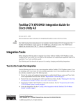
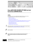
1
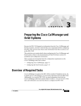
Ericsson MD-110 Serial Integration
Guide
Cisco Unity
Corporate Headquarters
Cisco Systems, Inc.
170 West Tasman Drive
San Jose, CA 95134-1706
USA
http://www.cisco.com
Tel: 408 526-4000
800 553-NETS (6387)
Fax: 408 526-4100
Text Part Number: OL-1290-01
THE SPECIFICATIONS AND INFORMATION REGARDING THE PRODUCTS IN THIS MANUAL ARE SUBJECT TO CHANGE WITHOUT
NOTICE. ALL STATEMENTS, INFORMATION, AND RECOMMENDATIONS IN THIS MANUAL ARE BELIEVED TO BE ACCURATE BUT
ARE PRESENTED WITHOUT WARRANTY OF ANY KIND, EXPRESS OR IMPLIED. USERS MUST TAKE FULL RESPONSIBILITY FOR
THEIR APPLICATION OF ANY PRODUCTS.
THE SOFTWARE LICENSE AND LIMITED WARRANTY FOR THE ACCOMPANYING PRODUCT ARE SET FORTH IN THE INFORMATION
PACKET THAT SHIPPED WITH THE PRODUCT AND ARE INCORPORATED HEREIN BY THIS REFERENCE. IF YOU ARE UNABLE TO
LOCATE THE SOFTWARE LICENSE OR LIMITED WARRANTY, CONTACT YOUR CISCO REPRESENTATIVE FOR A COPY.
The Cisco implementation of TCP header compression is an adaptation of a program developed by the University of California, Berkeley (UCB) as
part of UCB’s public domain version of the UNIX operating system. All rights reserved. Copyright © 1981, Regents of the University of California.
NOTWITHSTANDING ANY OTHER WARRANTY HEREIN, ALL DOCUMENT FILES AND SOFTWARE OF THESE SUPPLIERS ARE
PROVIDED “AS IS” WITH ALL FAULTS. CISCO AND THE ABOVE-NAMED SUPPLIERS DISCLAIM ALL WARRANTIES, EXPRESSED
OR IMPLIED, INCLUDING, WITHOUT LIMITATION, THOSE OF MERCHANTABILITY, FITNESS FOR A PARTICULAR PURPOSE AND
NONINFRINGEMENT OR ARISING FROM A COURSE OF DEALING, USAGE, OR TRADE PRACTICE.
IN NO EVENT SHALL CISCO OR ITS SUPPLIERS BE LIABLE FOR ANY INDIRECT, SPECIAL, CONSEQUENTIAL, OR INCIDENTAL
DAMAGES, INCLUDING, WITHOUT LIMITATION, LOST PROFITS OR LOSS OR DAMAGE TO DATA ARISING OUT OF THE USE OR
INABILITY TO USE THIS MANUAL, EVEN IF CISCO OR ITS SUPPLIERS HAVE BEEN ADVISED OF THE POSSIBILITY OF SUCH
DAMAGES.
AccessPath, AtmDirector, Browse with Me, CCIP, CCSI, CD-PAC, CiscoLink, the Cisco Powered Network logo, Cisco Systems Networking
Academy, the Cisco Systems Networking Academy logo, Fast Step, Follow Me Browsing, FormShare, FrameShare, GigaStack, IGX, Internet
Quotient, IP/VC, iQ Breakthrough, iQ Expertise, iQ FastTrack, the iQ Logo, iQ Net Readiness Scorecard, MGX, the Networkers logo, Packet,
RateMUX, ScriptBuilder, ScriptShare, SlideCast, SMARTnet, TransPath, Unity, Voice LAN, Wavelength Router, and WebViewer are trademarks
of Cisco Systems, Inc.; Changing the Way We Work, Live, Play, and Learn, Discover All That’s Possible, and Empowering the Internet Generation,
are service marks of Cisco Systems, Inc.; and Aironet, ASIST, BPX, Catalyst, CCDA, CCDP, CCIE, CCNA, CCNP, Cisco, the Cisco Certified
Internetwork Expert logo, Cisco IOS, the Cisco IOS logo, Cisco Systems, Cisco Systems Capital, the Cisco Systems logo, Enterprise/Solver,
EtherChannel, EtherSwitch, FastHub, FastSwitch, IOS, IP/TV, LightStream, MICA, Network Registrar, PIX, Post-Routing, Pre-Routing, Registrar,
StrataView Plus, Stratm, SwitchProbe, TeleRouter, and VCO are registered trademarks of Cisco Systems, Inc. and/or its affiliates in the U.S. and
certain other countries.
All other trademarks mentioned in this document or Web site are the property of their respective owners. The use of the word partner does not imply
a partnership relationship between Cisco and any other company. (0106R)
Ericsson MD-110 Serial Integration Guide
Copyright © 2001, Cisco Systems, Inc.
All rights reserved.
C O N T E N T S
Preface v
Purpose v
Audience v
Organization vi
Conventions vi
Cisco Unity Documentation vii
Obtaining Documentation viii
Obtaining Technical Assistance x
CHAPTER
1
Ericsson MD-110 Serial Integration 1-1
Integration Overview 1-1
Integration Description 1-3
Configuring Cisco Unity for the Integration 1-5
Programming the Phone System 1-7
Testing the Integration 1-9
CHAPTER
2
Dual Phone System Integration 2-1
Dual Phone System Integration Overview 2-1
Changing Cisco Unity Administrator Settings 2-3
Changing the Number of Installed Ports 2-8
APPENDIX
A
Exiting and Starting the Cisco Unity Software and Server A-1
Exiting the Cisco Unity Software A-1
Ericsson MD-110 Serial Integration Guide
OL-1290-01
iii
Contents
Shutting Down or Restarting the Cisco Unity Server A-2
Starting the Cisco Unity Software A-2
APPENDIX
B
Assigning Dialogic Ports for a Dual Phone System Integration B-1
Ericsson MD-110 Serial Integration Guide
iv
OL-1290-01
Preface
This preface describes the purpose, audience, organization, and conventions of the
Ericsson MD-110 Serial Integration Guide. It also provides information on how
to obtain related documentation.
Purpose
The Ericsson MD-110 Serial Integration Guide provides instructions for
integrating the phone system with the Cisco Unity voice messaging system. This
guide includes:
•
An overview of the process.
•
The requirements for setting up the integration.
•
A description of how the integration works.
•
The features supported by the integration.
•
Descriptions of procedural tasks.
Audience
The Ericsson MD-110 Serial Integration Guide is written for technicians who
configure the phone system and Cisco Unity to work with each other. This guide
requires knowledge of and access to both the phone system and the voice
messaging system.
Ericsson MD-110 Serial Integration Guide
OL-1290-01
v
Preface
Organization
Organization
Chapter 1 of the Ericsson MD-110 Serial Integration Guide describes the steps
needed to integrate the phone system and the voice messaging system.
Chapter 2 describes the steps needed for a “dual phone system integration”—an
integration of the voice messaging system with both Cisco CallManager and a
traditional, circuit-switched phone system at the same time.
Conventions
The Ericsson MD-110 Serial Integration Guide uses the following conventions.
Table 1
Ericsson MD-110 Serial Integration Guide conventions
Convention
Description
boldfaced text
Boldfaced text is used for:
•
Key and button names. (Example: Click OK.)
•
Information that you enter. (Example: Enter
Administrator in the User Name box.)
<>
(angle brackets)
Angle brackets are used around parameters for which you
supply a value. (Example: In the Command Prompt
window, enter ping <IP address>.)
(hyphen)
Hyphens separate keys that must be pressed
simultaneously (for example, Ctrl-Alt-Delete).
>
(right angle
bracket)
A right angle bracket is used to separate selections that
you make:
•
On menus. (Example: On the Windows Start menu,
click Settings > Control Panel > Phone and
Modem Options.)
•
In the navigation bar of the Cisco Unity
Administrator. (Example: Go to System >
Configuration > Settings.)
Ericsson MD-110 Serial Integration Guide
vi
OL-1290-01
Preface
Cisco Unity Documentation
The Ericsson MD-110 Serial Integration Guide also uses the following
convention:
Caution
Means reader be careful. In this situation, you might do something that could
result in equipment damage or loss of data.
Cisco Unity Documentation
Table 2
Cisco Unity Documentation Set
Document
Location
Cisco Unity Customization Worksheets
Available in PDF format on the Cisco Unity
Documentation compact disc and on Cisco.com at
http://www.cisco.com/univercd/cc/td/doc/product/
voice/c_unity/index.htm.
Cisco Unity Release Notes
Available in print and on Cisco.com at
http://www.cisco.com/univercd/cc/td/doc/product/
voice/c_unity/index.htm.
AV-Cisco TSP Release Notes
Available on Cisco.com at http://www.cisco.com/
univercd/cc/td/doc/product/voice/c_unity/index.htm.
Cisco Unity Installation Guide
Available in print, and in HTML and PDF formats on
the Cisco Unity Documentation compact disc and on
Cisco.com at http://www.cisco.com/univercd/
cc/td/doc/product/voice/c_unity/index.htm.
Cisco Unity System Administration Guide
Available in HTML and PDF formats on the
Cisco Unity Documentation compact disc and on
Cisco.com at http://www.cisco.com/univercd/
cc/td/doc/product/voice/c_unity/index.htm.
Also available in the Cisco Unity Administrator Help.
Ericsson MD-110 Serial Integration Guide
OL-1290-01
vii
Preface
Obtaining Documentation
Table 2
Cisco Unity Documentation Set
Document
Location
Cisco Unity Troubleshooting Guide
Available in HTML and PDF formats on the
Cisco Unity Documentation compact disc and on
Cisco.com at http://www.cisco.com/univercd/
cc/td/doc/product/voice/c_unity/index.htm.
Also available in the Cisco Unity Administrator Help.
Cisco Unity User Guide
Available in print and PDF formats on the Cisco Unity
Documentation compact disc and on Cisco.com at
http://www.cisco.com/univercd/
cc/td/doc/product/voice/c_unity/index.htm.
Cisco Unity at a Glance for Standard
Conversation card
Available in print and PDF formats on the Cisco Unity
Documentation compact disc and on Cisco.com at
http://www.cisco.com/univercd/
cc/td/doc/product/voice/c_unity/index.htm.
Cisco Unity at a Glance for Optional
Conversation card
Available in print and PDF formats on the Cisco Unity
Documentation compact disc and on Cisco.com at
http://www.cisco.com/univercd/
cc/td/doc/product/voice/c_unity/index.htm.
Obtaining Documentation
The following sections provide sources for obtaining documentation from Cisco
Systems.
World Wide Web
You can access the most current Cisco documentation on the World Wide Web at
the following sites:
•
http://www.cisco.com
•
http://www-china.cisco.com
•
http://www-europe.cisco.com
Ericsson MD-110 Serial Integration Guide
viii
OL-1290-01
Preface
Obtaining Documentation
Documentation CD-ROM
Cisco documentation and additional literature are available in a CD-ROM
package, which ships with your product. The Documentation CD-ROM is updated
monthly and may be more current than printed documentation. The CD-ROM
package is available as a single unit or as an annual subscription.
Ordering Documentation
Cisco documentation is available in the following ways:
•
Registered Cisco Direct Customers can order Cisco Product documentation
from the Networking Products MarketPlace:
http://www.cisco.com/cgi-bin/order/order_root.pl
•
Registered Cisco.com users can order the Documentation CD-ROM through
the online Subscription Store:
http://www.cisco.com/go/subscription
•
Nonregistered Cisco.com users can order documentation through a local
account representative by calling Cisco corporate headquarters (California,
USA) at 408 526-7208 or, in North America, by calling 800
553-NETS(6387).
Documentation Feedback
If you are reading Cisco product documentation on the World Wide Web, you can
submit technical comments electronically. Click Feedback in the toolbar and
select Documentation. After you complete the form, click Submit to send it to
Cisco.
You can e-mail your comments to [email protected].
To submit your comments by mail, write to the following address:
Attn Document Resource Connection
Cisco Systems, Inc.
170 West Tasman Drive
San Jose, CA 95134-9883
We appreciate your comments.
Ericsson MD-110 Serial Integration Guide
OL-1290-01
ix
Preface
Obtaining Technical Assistance
Obtaining Technical Assistance
Cisco provides Cisco.com as a starting point for all technical assistance.
Customers and partners can obtain documentation, troubleshooting tips, and
sample configurations from online tools. For Cisco.com registered users,
additional troubleshooting tools are available from the TAC website.
Cisco.com
Cisco.com is the foundation of a suite of interactive, networked services that
provides immediate, open access to Cisco information and resources at anytime,
from anywhere in the world. This highly integrated Internet application is a
powerful, easy-to-use tool for doing business with Cisco.
Cisco.com provides a broad range of features and services to help customers and
partners streamline business processes and improve productivity. Through
Cisco.com, you can find information about Cisco and our networking solutions,
services, and programs. In addition, you can resolve technical issues with online
technical support, download and test software packages, and order Cisco learning
materials and merchandise. Valuable online skill assessment, training, and
certification programs are also available.
Customers and partners can self-register on Cisco.com to obtain additional
personalized information and services. Registered users can order products, check
on the status of an order, access technical support, and view benefits specific to
their relationships with Cisco.
To access Cisco.com, go to the following website:
http://www.cisco.com
Technical Assistance Center
The Cisco TAC website is available to all customers who need technical assistance
with a Cisco product or technology that is under warranty or covered by a
maintenance contract.
Ericsson MD-110 Serial Integration Guide
x
OL-1290-01
Preface
Obtaining Technical Assistance
Contacting TAC by Using the Cisco TAC Website
If you have a priority level 3 (P3) or priority level 4 (P4) problem, contact TAC
by going to the TAC website:
http://www.cisco.com/tac
P3 and P4 level problems are defined as follows:
•
P3—Your network performance is degraded. Network functionality is
noticeably impaired, but most business operations continue.
•
P4—You need information or assistance on Cisco product capabilities,
product installation, or basic product configuration.
In each of the above cases, use the Cisco TAC website to quickly find answers to
your questions.
To register for Cisco.com, go to the following website:
http://www.cisco.com/register/
If you cannot resolve your technical issue by using the TAC online resources,
Cisco.com registered users can open a case online by using the TAC Case Open
tool at the following website:
http://www.cisco.com/tac/caseopen
Contacting TAC by Telephone
If you have a priority level 1(P1) or priority level 2 (P2) problem, contact TAC by
telephone and immediately open a case. To obtain a directory of toll-free numbers
for your country, go to the following website:
http://www.cisco.com/warp/public/687/Directory/DirTAC.shtml
P1 and P2 level problems are defined as follows:
•
P1—Your production network is down, causing a critical impact to business
operations if service is not restored quickly. No workaround is available.
•
P2—Your production network is severely degraded, affecting significant
aspects of your business operations. No workaround is available.
Ericsson MD-110 Serial Integration Guide
OL-1290-01
xi
Preface
Obtaining Technical Assistance
Ericsson MD-110 Serial Integration Guide
xii
OL-1290-01
C H A P T E R
1
Ericsson MD-110 Serial Integration
Integration Overview
Before performing the following integration steps, confirm that the Cisco Unity™
server is ready for the integration by completing the appropriate tasks in Chapters
1 through 3 of the Cisco Unity Installation Guide.
Integration Steps
Follow these steps to set up this integration.
1.
Review the system and equipment requirements to confirm that all phone
system and Cisco Unity server requirements have been met. See the
“Requirements” section on page 1-2.
2.
Configure Cisco Unity for the integration. See the “Configuring Cisco Unity
for the Integration” section on page 1-5.
3.
Program the phone system and extensions. See the “Programming the Phone
System” section on page 1-7.
4.
Test the integration. See the “Testing the Integration” section on page 1-9.
Ericsson MD-110 Serial Integration Guide
OL-1290-01
1-1
Chapter 1
Ericsson MD-110 Serial Integration
Integration Overview
Requirements
The Ericsson MD-110 integration supports configurations of the following
components:
Phone System
•
Ericsson MD-110
•
Software level BC6 or later
•
ICU card installed to provide the serial data port
•
The serial data port in the phone system connected to a serial port (COM1 is
the default) on the Unity server with an RS-232 serial cable
•
The voice messaging ports in the phone system connected to the voice cards
in the Cisco Unity server
•
The phone system ready for the integration as described in the installation
guide for the phone system
Cisco Unity Server
Caution
•
The Dialogic® D/41EPCI ™, D/120JCT-LS ™, or D/120JCT-Euro ™ voice
cards installed
•
Cisco Unity installed and ready for the integration as described in the
Cisco Unity Installation Guide
To prevent Windows from mistaking the serial connection for a serial mouse
when rebooting the Cisco Unity server, confirm that the Boot.ini file is set
according to instructions. Otherwise, the integration will not work properly.
For details on setting up the Boot.ini file, refer to “Installing Windows 2000
Server” in Chapter 3 of the Cisco Unity Installation Guide.
•
A system key that enables the integration and the appropriate number of voice
messaging ports
•
An available serial port (COM1 is the default)
Ericsson MD-110 Serial Integration Guide
1-2
OL-1290-01
Chapter 1
Ericsson MD-110 Serial Integration
Integration Description
Integration Description
The Ericsson MD-110 integration uses a data link, which consists of an RS-232
serial cable connecting the phone system and the Cisco Unity server. The voice
messaging lines from the phone system connect to the analog voice cards in the
Cisco Unity server. The following illustration shows the required connections.
Connections Between the Phone System and Cisco Unity
Phone system
Cisco Unity server
RS-232 serial cable
Analog lines
55423
Figure 1-1
The phone system sends the following information through the data link:
•
The extension of the called party
•
The reason for the forward (the extension is busy, does not answer, or is set
to forward all calls)
•
The extension of the calling party (for internal calls) or the phone number of
the calling party (if it is an external call and the system uses caller ID)
Cisco Unity uses this information to answer the call appropriately. For example,
a call forwarded to Cisco Unity is answered with the personal greeting of the
subscriber. If the phone system routes the call to Cisco Unity without this
information, Cisco Unity answers with the opening greeting.
Ericsson MD-110 Serial Integration Guide
OL-1290-01
1-3
Chapter 1
Ericsson MD-110 Serial Integration
Integration Description
Integration Features
The Ericsson MD-110 integration with Cisco Unity provides the following
features:
Call forward to personal greeting
When an incoming call is routed to an
unanswered or busy extension, the call is
forwarded to the voice mail of the subscriber.
The caller then hears the personal greeting of
the subscriber and can leave a message.
Caller ID
Cisco Unity receives caller ID information
from the phone system (if available). This
information appears in the subject line of the
message in the desktop messaging
application.
Easy message access
A subscriber can retrieve messages without
entering an ID. Cisco Unity identifies a
subscriber based on the extension from which
the call originated. A password may be
required.
Identified subscriber messaging
Cisco Unity automatically identifies a
subscriber who leaves a message during a
forwarded internal call, based on the
extension from which the call originated.
Message waiting indication
When a message is waiting for a subscriber,
Cisco Unity notifies the phone system to
activate the message waiting indicator (MWI)
on the subscriber’s extension (a lamp or a
stutter dial tone).
Ericsson MD-110 Serial Integration Guide
1-4
OL-1290-01
Chapter 1
Ericsson MD-110 Serial Integration
Configuring Cisco Unity for the Integration
Configuring Cisco Unity for the Integration
After ensuring that the Cisco Unity server is ready for the integration by
completing the appropriate tasks in Chapters 1 through 3 of the Cisco Unity
Installation Guide, perform the following procedures to confirm that the
integration is enabled and to enter the port settings.
To confirm that the integration is enabled
Step 1
On the Cisco Unity server, go to the Cisco Unity Administrator by doing one of
the following:
•
In Internet Explorer, go to http://<server name>/web/sa.
•
Double-click the desktop shortcut to the Cisco Unity Administrator.
Step 2
Go to System > Licensing > Licensed Features.
Step 3
In the Integration field, confirm that the setting is Serial for a single phone system
integration or Multiple Integrations for a dual phone system integration.
Step 4
If the setting is not Serial or Multiple Integrations, contact your sales
representative for the necessary system key.
Step 5
Go to System > Switch. Confirm that the settings match those in the following
table. If the settings are incorrect, integration features may not be enabled.
Table 1-1
Step 6
Switch Settings
Switch Parameter
Required Setting
Manufacturer
Ericsson
Model
MD110
Switch PBX Software Version
All
Integration
Serial
Click the Save icon.
Ericsson MD-110 Serial Integration Guide
OL-1290-01
1-5
Chapter 1
Ericsson MD-110 Serial Integration
Configuring Cisco Unity for the Integration
To enter port settings
Step 1
In the Cisco Unity Administrator, go to System > Ports.
Step 2
Select a port in the table.
Step 3
Indicate the settings for the port.
For a hunt group, use the first voice-messaging ports for incoming calls and the
last ports to dial out. This helps minimize the possibility of a collision, in which
an incoming call arrives on a port at the same time that Cisco Unity takes the port
off-hook to dial out.
Step 4
Type the extension for the port.
Step 5
Repeat Steps 2 through 4 for the remaining ports.
Step 6
Click the Save icon.
Step 7
For the settings to take effect, exit the Cisco Unity software. For more
information, see the appendix, “Exiting and Starting the Cisco Unity Software and
Server.”
If your phone system uses extension numbers that begin with zero (for example,
0123 or 09876), perform the following procedure.
Note that after the procedure is performed all extension numbers must have the
same number of digits. In this case, for example, 0123 and 1234 are both allowed,
but 0123 and 234 are not allowed.
To enable extensions beginning with zero
Step 1
On the Cisco Unity server, navigate to the \CommServer\Intlib directory on the
drive you installed Cisco Unity.
Step 2
In the Intlib directory, locate the file Ericsson0001.ini.
Step 3
Open the file in a text editor.
Step 4
In the Configuration section of the file, locate the following line:
AllowZeroLeadingExtensions=0
Step 5
Change the final digit to 1, so the line reads:
AllowZeroLeadingExtensions=1
Ericsson MD-110 Serial Integration Guide
1-6
OL-1290-01
Chapter 1
Ericsson MD-110 Serial Integration
Programming the Phone System
Step 6
Save the file and close the text editor.
Step 7
For the setting to take effect, exit the Cisco Unity software, then restart the server.
For more information, see the appendix, “Exiting and Starting the Cisco Unity
Software and Server.”
Programming the Phone System
If you use programming options other than those supplied in the following
procedure, the performance of the integration may be affected.
To program the phone system
Step 1
Use the EXTEI command to program the ELU extensions for connecting to the
voice messaging ports. You must program the ports for:
•
No call waiting
•
No diversion
•
No conferencing
•
No intrusion
The ELU1 extension does not support message waiting indication for analog
phones. The ELU24 extension provides stutter dial tone for message waiting
indication.
Step 2
Use the VMPOI command to match the extensions and their ICU port numbers
with the voice messaging ports on the Cisco Unity server. For example, the
Cisco Unity port 01 must match Ericsson ICU port 1, extension 3500;
Cisco Unity port 02 must match Ericsson ICU port 2, extension 3501; and so on.
The results of this example would be as follows:
VMPOI:ICUIND=1,DIR=3500,PORT=01
VMPOI:ICUIND=2,DIR=3501,PORT=02
Ericsson MD-110 Serial Integration Guide
OL-1290-01
1-7
Chapter 1
Ericsson MD-110 Serial Integration
Programming the Phone System
Step 3
Use the GH command to create a hunt group for the voice messaging ports.
Make sure that the phone system sends calls only to Cisco Unity voice ports that
are set to Answer Calls on the System > Ports page in the Cisco Unity
Administrator. Calls sent to a voice port not set to Answer Calls cannot be
answered by Cisco Unity. And, if certain voice cards are installed, the call will not
be dropped, but the port remains unavailable for use until the Cisco Unity server
is restarted.
Step 4
Use the VMPOI command to associate the hunt group with Cisco Unity.
Step 5
Use the KS command to provide message waiting indication on DTS phones.
Step 6
Program each phone to forward calls to the pilot number assigned to the voice
messaging ports, based on one of the following Cisco Unity call transfer types.
Table 1-2
Call Transfer Types
Transfer type
Usage
Release transfer
(blind transfer)
Program the phone to forward calls to the pilot
number when:
Supervised transfer
•
The extension is busy
•
The call is not answered
Program the phone to forward calls to the pilot
number only when the call is not answered.
Confirm that call forwarding is disabled when the
extension is busy.
Ericsson MD-110 Serial Integration Guide
1-8
OL-1290-01
Chapter 1
Ericsson MD-110 Serial Integration
Testing the Integration
Testing the Integration
To test whether Cisco Unity and the phone system are integrated correctly,
perform the procedures in the order listed.
If any of the steps indicates a failure, see the following documentation as
appropriate:
•
The installation guide for the phone system
•
Cisco Unity Troubleshooting Guide
•
This integration guide
To set up the test configuration
Step 1
Set up two test extensions (Phone 1 and Phone 2) on the same phone system that
Cisco Unity is connected to.
Step 2
Set Phone 1 to forward calls to the Cisco Unity pilot number when calls are not
answered.
Step 3
In the Cisco Unity Administrator, go to Subscribers > Subscribers > Profile.
If Example Subscriber is not displayed, click the Find icon (the magnifying glass)
in the title bar, then click Find, and select Example Subscriber in the list that
appears.
Step 4
In the Extension field, enter the extension of Phone 1.
Step 5
Click the Save icon.
Step 6
In the navigation bar, click Call Transfer to go to Subscribers > Subscribers >
Call Transfer for Example Subscriber.
For more information on transfer settings, refer to the “Subscriber Template Call
Transfer Settings” section in the Help for the Cisco Unity Administrator.
Step 7
Under Transfer Incoming Calls, click Yes, Ring Subscriber’s Extension, and
confirm that the extension number is for Phone 1.
Step 8
Under Transfer Type, click Release to Switch.
Step 9
Click the Save icon.
Step 10
In the navigation bar, click Messages to go to Subscribers > Subscribers >
Messages for Example Subscriber.
Ericsson MD-110 Serial Integration Guide
OL-1290-01
1-9
Chapter 1
Ericsson MD-110 Serial Integration
Testing the Integration
Step 11
Under Message Waiting Indicators (MWIs), check Use MWI for Message
Notification.
Step 12
In the Extension field, enter x.
Step 13
Click the Save icon.
Step 14
Open the Status Monitor by doing one of the following:
•
In Internet Explorer, go to http://<server name>/web/sm.
•
Double-click the desktop shortcut to the Status Monitor.
•
In the Windows systray, right-click the Cisco Unity icon and click Status
Monitor.
To test an external call with release transfer
Step 1
From Phone 2, enter the access code necessary to get an outside line, then enter
the number outside callers use to dial directly to Cisco Unity.
Step 2
On the Status Monitor, note the port that handles this call.
Step 3
When you hear the opening greeting, enter the extension for Phone 1. Hearing the
opening greeting means that the port is configured correctly.
Step 4
Confirm that Phone 1 rings and that you hear a ringback tone on Phone 2. Hearing
a ringback tone means that Cisco Unity released the call and transferred it to
Phone 1.
Step 5
Do not answer Phone 1, and confirm that the state of the port handling the call
changes to “Idle.” This state means that release transfer succeeds.
Step 6
Confirm that, after the number of rings that the phone system is set to wait, the
call is forwarded to Cisco Unity and that you hear the greeting for Example
Subscriber. Hearing the greeting means that the phone system forwarded the
unanswered call and the call-forward information to Cisco Unity, which correctly
interpreted the information.
Step 7
On the Status Monitor, note the port that handles this call.
Step 8
Leave a message for Example Subscriber and hang up Phone 2.
Step 9
On the Status Monitor, confirm that the state of the port handling the call changes
to “Idle.” This state means that the port was successfully released when the call
ended.
Ericsson MD-110 Serial Integration Guide
1-10
OL-1290-01
Chapter 1
Ericsson MD-110 Serial Integration
Testing the Integration
Step 10
Confirm that the MWI on Phone 1 is activated. The activated MWI means that the
phone system and Cisco Unity are successfully integrated for turning on MWIs.
To test an internal call with release transfer
Step 1
From Phone 1, enter the internal pilot number for Cisco Unity.
Step 2
When asked for your password, enter 12345. Hearing the request for your
password means that the phone system sent the necessary call information to
Cisco Unity, which correctly interpreted the information.
Step 3
Confirm that you hear the recorded voice name for Example Subscriber. Hearing
the voice name means that Cisco Unity correctly identified the subscriber by the
extension.
Step 4
When asked whether you want to listen to your messages, press 1.
Step 5
After listening to the message, press 3 to delete the message.
Step 6
Confirm that the MWI on Phone 1 is deactivated. The deactivated MWI means
that the phone system and Cisco Unity are successfully integrated for turning off
MWIs.
Step 7
Hang up Phone 1.
Step 8
On the Status Monitor, confirm that the state of the port handling the call changes
to “Idle.” This state means that the port was successfully released when the call
ended.
To set up supervised transfer on Cisco Unity
Step 1
In the Cisco Unity Administrator, go to Subscribers > Subscribers > Call
Transfer.
If Example Subscriber is not displayed, click the Find icon (the magnifying glass)
in the title bar, then click Find, and select Example Subscriber in the list that
appears.
For more information on transfer settings, refer to the “Subscriber Template Call
Transfer Settings” section in the Help for the Cisco Unity Administrator.
Step 2
Under Transfer Type, click Supervise Transfer.
Ericsson MD-110 Serial Integration Guide
OL-1290-01
1-11
Chapter 1
Ericsson MD-110 Serial Integration
Testing the Integration
Step 3
Set the Rings to Wait For field to 3.
Step 4
Click the Save icon.
To test supervised transfer
Step 1
From Phone 2, enter the access code necessary to get an outside line, then enter
the number outside callers use to dial directly to Cisco Unity.
Step 2
On the Status Monitor, note the port that handles this call.
Step 3
When you hear the opening greeting, enter the extension for Phone 1. Hearing the
opening greeting means that the port is configured correctly.
Step 4
Confirm that Phone 1 rings and that you do not hear a ringback tone on Phone 2.
Instead, you should hear the indication your phone system uses to mean that the
call is on hold (for example, music or beeps).
Step 5
Do not answer Phone 1, and confirm that the state of the port handling the call
remains “Busy.” This state and hearing an indication that you are on hold mean
that Cisco Unity is supervising the transfer.
Step 6
Confirm that, after three rings, you hear the greeting for Example Subscriber.
Hearing the greeting means that Cisco Unity successfully recalled the
supervised-transfer call.
Step 7
During the greeting, hang up Phone 2.
Step 8
On the Status Monitor, confirm that the state of the port handling the call changes
to “Idle.” This state means that the port was successfully released when the call
ended.
To return Example Subscriber to the default settings
Step 1
In the Cisco Unity Administrator, go to Subscribers > Subscribers > Call
Transfer.
If Example Subscriber is not displayed, click the Find icon (the magnifying glass)
in the title bar, then click Find, and select Example Subscriber in the list that
appears.
Ericsson MD-110 Serial Integration Guide
1-12
OL-1290-01
Chapter 1
Ericsson MD-110 Serial Integration
Testing the Integration
Step 2
Under Transfer Incoming Calls, click No (Send Directly to Subscriber’s
Greeting).
Step 3
In the navigation bar, click Profile to go to Subscribers > Subscribers > Profile.
Step 4
In the Extension field, enter 99990.
Step 5
Click the Save icon.
Step 6
In the navigation bar, click Messages to go to Subscribers > Subscribers >
Messages for Example Subscriber.
Step 7
Under Message Waiting Indicators (MWIs), uncheck Use MWI for Message
Notification.
Step 8
Click the Save icon.
Ericsson MD-110 Serial Integration Guide
OL-1290-01
1-13
Chapter 1
Ericsson MD-110 Serial Integration
Testing the Integration
Ericsson MD-110 Serial Integration Guide
1-14
OL-1290-01
C H A P T E R
2
Dual Phone System Integration
Cisco Unity can be integrated with one each of the following phone systems at the
same time:
•
A traditional, circuit-switched phone system. Any traditional phone system
that Cisco Unity integrates with can be used in a dual phone system
integration.
•
Cisco CallManager.
All extensions for subscribers and call handlers must be unique regardless of
which phone system a subscriber (or call handler) uses. To transfer calls from one
phone system to the other, Cisco Unity must dial the same access codes that a
subscriber dials when calling someone on the other phone system.
Dual Phone System Integration Overview
Before performing the following integration steps, confirm that the Cisco Unity™
server is ready for the integration by completing the appropriate tasks in Chapters
1 through 3 of the Cisco Unity Installation Guide.
Integration Steps When No Phone Systems Are Installed
Follow these steps to set up the dual phone system integration when no phone
systems are installed.
1.
Install the traditional phone system.
Ericsson MD-110 Serial Integration Guide
OL-1290-01
2-1
Chapter 2
Dual Phone System Integration
Dual Phone System Integration Overview
2.
Integrate the traditional phone system and Cisco Unity. See Chapter 1 of this
integration guide.
3.
Install Cisco CallManager.
4.
Integrate Cisco CallManager and Cisco Unity. See the PDF of the Cisco
CallManager Integration Guide, which is located In the Integrations
directory on the Cisco Unity Documentation compact disc.
5.
Change the Cisco Unity Administrator settings. See the “Changing
Cisco Unity Administrator Settings” section on page 2-3.
Integration Steps When a Traditional Phone System Is Already
Installed
Follow these steps to set up the dual phone system integration when the traditional
phone system is already installed and Cisco CallManager is being newly installed.
1.
Install Cisco CallManager.
2.
Integrate Cisco CallManager and Cisco Unity. See the PDF of the Cisco
CallManager Integration Guide, which is located in the Integrations
directory on the Cisco Unity Documentation compact disc.
3.
Change the Cisco Unity Administrator settings. See the “Changing
Cisco Unity Administrator Settings” section on page 2-3.
Integration Steps When Cisco CallManager Is Already Installed
Follow these steps to set up the dual phone system integration when Cisco
CallManager is already installed and a traditional phone system is being newly
installed.
1.
Remove the existing AV-Cisco TSP on Cisco Unity. See the “To remove the
existing AV-Cisco TSP” section on page 2-9.
2.
Install the traditional phone system.
3.
Integrate the traditional phone system and Cisco Unity. See Chapter 1 of this
integration guide.
4.
Reinstall the AV-Cisco TSP. See the “To reinstall the AV-Cisco TAPI service
provider” section on page 2-9.
Ericsson MD-110 Serial Integration Guide
2-2
OL-1290-01
Chapter 2
Dual Phone System Integration
Changing Cisco Unity Administrator Settings
5.
Change the Cisco Unity Administrator settings. See the “Changing
Cisco Unity Administrator Settings” section on page 2-3.
Requirements
The dual phone system integration supports configurations of the following
components:
•
A Cisco Unity system key with the integration type set to “Multiple
integrations” and with the appropriate number of voice messaging ports
enabled.
•
The Cisco Unity server set up and Cisco Unity 3.0(1) or later installed, as
described in the Cisco Unity Installation Guide.
•
A traditional phone system installed and integrated with Cisco Unity. For
details, see Chapter 1 of this integration guide. The traditional phone system
(including the voice card software used in the integration) must be installed
and integrated with Cisco Unity before Cisco CallManager is integrated.
•
Cisco CallManager, version 3.1(1) or later, and the AV-Cisco TAPI service
provider (TSP) installed and configured. For information about integrating
Cisco Unity with Cisco CallManager and the AV-Cisco TAPI Service
Provider, see the PDF of the Cisco CallManager Integration Guide, which is
located on the Cisco Unity Documentation compact disc.
Changing Cisco Unity Administrator Settings
After Cisco Unity is installed and the phone systems have been separately
integrated, you need to adjust settings on pages in the Cisco Unity Administrator
so that Cisco Unity can work with both phone systems.
Follow these steps to set up the dual phone system integration.
1.
Specify settings for the traditional phone system on the System > Switch >
Switch page. For details, see the “To specify switch settings for the traditional
phone system” section on page 2-4.
Ericsson MD-110 Serial Integration Guide
OL-1290-01
2-3
Chapter 2
Dual Phone System Integration
Changing Cisco Unity Administrator Settings
Caution
Caution
Specify settings for the traditional phone system before specifying settings for
Cisco CallManager. You must proceed in this order, or the integration may not
work.
2.
Specify settings for Cisco CallManager on the IP Switch page. For details,
see the “To specify switch settings for Cisco CallManager” section on
page 2-5.
3.
On the Ports page, assign port ranges to the traditional phone system first,
then to CallManager, and adjust settings for the ports assigned to each phone
system. For details, see the “To modify voice port settings” section on
page 2-5.
4.
Select the phone system that subscribers and call handlers use. For details, see
the “To select which phone system subscribers and call handlers use” section
on page 2-7.
5.
Select the phone system that Cisco Unity uses when dialing out to send
message notifications. For details, see the “To select which phone system
Cisco Unity uses for message notification” section on page 2-7.
If you need to add or remove voice cards or uninstall the voice card software
after the dual phone system integration is set up, you must also reinstall the
AV-Cisco TAPI service provider. Do not reinstall the AV-Cisco TAPI service
provider until after you have set up the voice cards or reinstalled the voice card
software. For more information, see the “Changing the Number of Installed
Ports” section on page 2-8.
To specify switch settings for the traditional phone system
Step 1
Go to System > Switch > Switch. The settings for the traditional phone system
selected during the Cisco Unity Setup program appear.
Step 2
In the Access Code field, enter the trunk access code that Cisco Unity must dial
to transfer calls to Cisco CallManager from the traditional phone system.
The access code is the same number that subscribers on the traditional phone
system dial to reach someone on the Cisco CallManager system.
Ericsson MD-110 Serial Integration Guide
2-4
OL-1290-01
Chapter 2
Dual Phone System Integration
Changing Cisco Unity Administrator Settings
Step 3
Adjust other settings as appropriate. For more information about the other settings
on the Switch page, see the online Help in the Cisco Unity Administrator.
Step 4
Click the Save icon, then click OK in the Warning dialog box.
To specify switch settings for Cisco CallManager
Step 1
Go to System > Switch > IP Switch.
Step 2
In the Set Active Switch Type section, enter values as shown in the following
table:
Table 2-1
Switch Settings
Switch Parameter
Required Setting
Manufacturer
Cisco
Model
CallManager
Switch PBX software version
3.01 or later
Integration
TAPI
Step 3
Click Set As Active, then click OK in the Warning dialog box.
Step 4
In the Access Code field, enter the trunk access code that Cisco Unity must dial
to transfer calls to the traditional phone system from Cisco CallManager.
The access code is the same number that subscribers on Cisco CallManager dial
to reach someone on the traditional phone system.
Step 5
Click the Save icon, then click OK in the Warning dialog box.
To modify voice port settings
Step 1
Go to System > Ports.
Ericsson MD-110 Serial Integration Guide
OL-1290-01
2-5
Chapter 2
Dual Phone System Integration
Changing Cisco Unity Administrator Settings
Step 2
Caution
In the Port Assignments section, indicate the range of ports to be assigned to the
traditional phone system. The port range for the traditional phone system is port
1 through x, where x is the number of ports on the installed voice cards. Do not
assign more ports to the traditional phone system than the number of ports on the
voice cards.
If you assign fewer voice ports to the traditional phone system than are
available on the installed voice cards, you must edit the registry for this port
range to take effect. Otherwise, all available voice ports on the voice cards are
used in the integration regardless of the Port Assignments settings. For
information on editing the registry for the port range, see the appendix
“Assigning Dialogic Ports for a Dual Phone System Integration.”
Step 3
In the Port Assignments section, indicate the range of ports to be assigned to
Cisco CallManager. The port range must begin with the next port after the last port
for the traditional phone system. The range for Cisco CallManager is x + 1
through y, where y is the port number of the last port displayed on the Ports page
or the number of licensed voice ports on the system key, whichever is lower. The
number of ports available for Cisco CallManager is the difference between the
number of licensed voice ports on the system key and the number of ports
assigned to the traditional phone system.
Step 4
Enter an extension for each port.
Step 5
Specify other settings as appropriate. For each phone system, confirm that an
appropriate number of ports are used to answer calls and to dial out for message
waiting indicators (MWIs), message notifications, and Media Master recordings
by phone.
Step 6
Click the Save icon.
Caution
The port range for each phone system must be set as specified in Steps 2 and
3 above. If there is a port range mismatch, Cisco Unity will be unable to
answer incoming calls and to dial out.
Ericsson MD-110 Serial Integration Guide
2-6
OL-1290-01
Chapter 2
Dual Phone System Integration
Changing Cisco Unity Administrator Settings
To select which phone system subscribers and call handlers use
For existing subscriber templates, subscriber accounts, and call handlers,
Cisco Unity uses the traditional phone system as its default. Therefore, during the
initial setup of the dual phone integration, you will modify only those pages that
will be using Cisco CallManager. Note that changes made to subscriber templates
do not affect existing subscriber accounts.
Step 1
In Cisco Unity Administrator, go to the appropriate page:
•
Subscribers > Subscriber Template > Profile
•
Subscribers > Subscribers > Profile
•
Call Management > Call Handlers > Profile
Step 2
In the Switch list, select the appropriate phone system.
Step 3
Adjust other settings as appropriate. For more information, see the online Help in
the Cisco Unity Administrator.
Caution
If the Switch setting on the Profile page for the subscriber or call handler does
not match the phone system actually used by a subscriber or call handler,
Cisco Unity will not be able to transfer calls to or from the subscriber or call
handler. Additionally, Cisco Unity will be unable to turn the MWIs for the
subscriber on or off and will be unable to reach the extension for the subscriber
when recording by phone with Media Master.
To select which phone system Cisco Unity uses for message notification
If subscribers use message notification, you can select which phone system
Cisco Unity dials out on when notifying subscribers of new messages. Note that
changes made to subscriber templates do not affect existing subscribers.
Step 1
In Cisco Unity Administrator, go to the appropriate page:
•
Subscribers > Subscriber Template > Message Notification
•
Subscribers > Message Notification.
Ericsson MD-110 Serial Integration Guide
OL-1290-01
2-7
Chapter 2
Dual Phone System Integration
Changing the Number of Installed Ports
Step 2
For each device, in the Switch list select the phone system that Cisco Unity uses
to dial out when notifying subscribers of new messages. Each notification device
can be associated with a specific phone system (except for text pagers).
Cisco Unity uses the phone system specified on the subscriber template’s Profile
page as the default.
Step 3
Caution
Adjust other settings as appropriate. For more information, see the online Help in
the Cisco Unity Administrator.
The selected phone system must have at least one port set to dial out for
message notifications on the System > Ports page. If the selected phone system
does not have any ports set for this function, notifications will fail.
Changing the Number of Installed Ports
After the dual phone system integration is set up, if you need to add or remove
voice cards or uninstall voice card software, follow these steps:
1.
Remove the existing AV-Cisco TAPI service provider. For details, see the “To
remove the existing AV-Cisco TSP” section on page 2-9.
2.
As appropriate, remove or add voice cards, or uninstall and reinstall the voice
card software. For information about removing Dialogic voice card software,
refer to the chapter “Adding, Changing, or Removing Voice Cards” in the
Cisco Unity Installation Guide.
3.
Reinstall the AV-Cisco TAPI service provider after you have set up the voice
cards or reinstalled the voice card software. For details, see “To reinstall the
AV-Cisco TAPI service provider” section on page 2-9.
4.
Adjust the port assignments on the System > Ports page. The voice messaging
ports must appear in this order in the list of ports: first are all the ports
connected to the traditional phone system, second are the ports connected to
CallManager.
Ericsson MD-110 Serial Integration Guide
2-8
OL-1290-01
Chapter 2
Dual Phone System Integration
Changing the Number of Installed Ports
If you completely remove the traditional phone system, you must adjust the port
assignments for Cisco CallManager on the System > Ports page, after the voice
cards and voice card software used in the integration with the traditional phone
system have been removed.
To remove the existing AV-Cisco TSP
Step 1
On the Cisco Unity server, log on to Windows as an administrator.
Step 2
Stop Cisco Unity (right-click the Cisco Unity icon in the system tray, then click
Stop Unity).
Step 3
On the Windows Start menu, click Settings > Control Panel > Add/Remove
Programs.
Step 4
In the list, click AV-Cisco TSP.
Step 5
Click Remove.
Step 6
Click Yes.
Step 7
Close Control Panel.
To reinstall the AV-Cisco TAPI service provider
Step 1
On the Cisco Unity server, log on to Windows as an administrator.
Step 2
On the Windows Start menu, click Settings > Control Panel.
Step 3
Double-click Phone and Modem Options. The Phone and Modem Options
dialog box appears.
Step 4
Click the Advanced tab.
Step 5
Click Add. The Add Driver dialog box appears.
Step 6
Click AV-Cisco Service Provider, then click Add. A dialog box appears
confirming the installation of the TSP.
Step 7
Click OK to close the dialog box.
Step 8
Click Close to close the Phone and Modem Options dialog box.
Step 9
Close Control Panel.
Ericsson MD-110 Serial Integration Guide
OL-1290-01
2-9
Chapter 2
Dual Phone System Integration
Changing the Number of Installed Ports
Step 10
Restart the Cisco Unity server.
Ericsson MD-110 Serial Integration Guide
2-10
OL-1290-01
A P P E N D I X
A
Exiting and Starting the Cisco Unity
Software and Server
Exiting the Cisco Unity Software
This section provides two procedures for exiting the software: from the
Cisco Unity server and from another computer.
To exit the Cisco Unity software from the Cisco Unity server
Step 1
If the system uses the automated attendant, route all calls to the operator.
Step 2
Log on to Windows as a Cisco Unity administrator.
Step 3
Right-click the Cisco Unity icon in the status area of the taskbar.
Step 4
Click Stop Cisco Unity. An “X” appears in the Cisco Unity icon when
Cisco Unity stops running.
Step 5
Press Ctrl-Alt-Delete, then lock or log off Windows to prevent access by
unauthorized users.
To exit the Cisco Unity software from another computer
Step 1
If the system uses the automated attendant, route all calls to the operator.
Step 2
Start Internet Explorer, and go to http://<Cisco Unity server name>/status. If
prompted, enter the name and password of a Cisco Unity administrator.
Ericsson MD-110 Serial Integration Guide
OL-1290-01
A-1
Appendix A
Exiting and Starting the Cisco Unity Software and Server
Shutting Down or Restarting the Cisco Unity Server
Step 3
In the Cisco Unity Status Monitor, under Shutting Down Unity, choose a method:
Cisco Unity stops running after all calls are finished, or Cisco Unity interrupts
calls in progress with a voice message, disconnects all calls, then stops running.
Step 4
Click Shut Down.
Shutting Down or Restarting the Cisco Unity Server
If an expansion chassis is connected to the Cisco Unity server, and if both the
expansion chassis and the server are turned off, turn on the expansion chassis
before you turn on the server. Otherwise, the server may not detect the voice cards
in the expansion chassis.
To shut down or restart the Cisco Unity server
Step 1
Exit the Cisco Unity software, if it is running, by using a procedure in the “Exiting
the Cisco Unity Software” section on page A-1.
Step 2
On the Windows Start menu, click Shut Down.
Step 3
Click Shut Down or Restart.
During a restart, the Cisco Unity software starts automatically.
When Cisco Unity starts successfully, three tones play and a check mark appears
in the Cisco Unity icon in the status area of the taskbar.
When Cisco Unity does not start successfully, two tones play and an “X” appears
in the Cisco Unity icon in the status area of the taskbar.
Starting the Cisco Unity Software
This section provides two procedures for starting the software: from the
Cisco Unity server and from another computer.
Ericsson MD-110 Serial Integration Guide
A-2
OL-1290-01
Appendix A
Exiting and Starting the Cisco Unity Software and Server
Starting the Cisco Unity Software
Cisco Unity is a Windows 2000 service that is configured to start automatically
when you turn on or restart the server. Do one of the following procedures only if
you exited the Cisco Unity software but did not restart the server.
Exchange must be running before you start the Cisco Unity software. Like
Cisco Unity, Exchange starts automatically when you turn on or restart the server.
If you exited Exchange manually but did not restart the Cisco Unity server, start
Exchange first.
To start the Cisco Unity software from the Cisco Unity server
Step 1
Log on to Windows as a Cisco Unity administrator.
Step 2
Right-click the Cisco Unity icon in the status area of the taskbar.
Step 3
Click Start Cisco Unity.
When Cisco Unity starts successfully, three tones play and a check mark appears
in the Cisco Unity icon.
When Cisco Unity does not start successfully, two tones play and an “X” appears
in the Cisco Unity icon.
Step 4
Press Ctrl-Alt-Delete, then lock or log off Windows to prevent access by
unauthorized users.
Step 5
If the system uses the automated attendant and you routed calls to the operator
before you exited the Cisco Unity software, reroute calls to Cisco Unity.
To start the Cisco Unity software from another computer
Step 1
Start Internet Explorer, and go to http://<Cisco Unity server name>/status. If
prompted, enter the name and password of a Cisco Unity administrator.
Step 2
In the Cisco Unity Status Monitor, click the System Status icon (the first icon),
at the top of the page.
Step 3
Click Start.
Step 4
If the system uses the automated attendant and you routed calls to the operator
before you exited the Cisco Unity software, reroute calls to Cisco Unity.
Ericsson MD-110 Serial Integration Guide
OL-1290-01
A-3
Appendix A
Exiting and Starting the Cisco Unity Software and Server
Starting the Cisco Unity Software
Ericsson MD-110 Serial Integration Guide
A-4
OL-1290-01
A P P E N D I X
B
Assigning Dialogic Ports for a Dual
Phone System Integration
In a dual phone system integration, Cisco Unity assigns a voice messaging port to
the traditional phone system for every port available on the installed voice cards
before assigning voice messaging ports to Cisco CallManager. The result is that
Cisco Unity may not have enough voice messaging ports remaining to assign to
Cisco CallManager.
The maximum number of voice messaging ports are assigned to the traditional
phone system in spite of the settings on the Ports page in the System
Administrator.
For example, a dual phone system integration might have the following
configuration:
•
A traditional phone system has a four-port voice card installed.
•
Cisco CallManager has six Voice Mail ports set up.
•
The Cisco Unity server has a system key enabled for a total of eight ports.
•
The Ports page on System Administrator indicates that Ports 1 and 2 are
assigned to the traditional phone system and Ports 3 through 8 are assigned
to Cisco CallManager.
Even so, Ports 1 through 4 (the total voice card ports) will be assigned to the
traditional phone system, and Ports 5 through 6 will be assigned to Cisco
CallManager.
If you want to assign fewer than the total voice card ports to the traditional phone
system, you must first set the Port assignments on the Ports page of the System
Administrator, then perform the following procedure.
Ericsson MD-110 Serial Integration Guide
OL-1290-01
B-1
Appendix B
Assigning Dialogic Ports for a Dual Phone System Integration
To set the Port assignments in the Registry
Step 1
On the Cisco Unity server, click Start > Run.
Step 2
In the Open field, enter Regedit and press Enter. The Registry Editor appears.
Step 3
Go to HKEY_LOCAL_MACHINE\Software\ActiveVoice\MIU\1.0\
Initialization\ServiceProvider <x>, where <x> is a number.
You will find several subkeys with this name.
Step 4
Locate the subkey in which the value Service Provider Name is D41MT.TSP.
Step 5
In this subkey, in the Edit menu click New > DWORD Value. A new value
appears in the subkey.
Step 6
Enter the name DeviceID Lower Bound and press Enter.
Step 7
Double-click the DeviceID Lower Bound value. The Edit DWORD Value dialog
box appears.
Step 8
In the Value Data field, enter 1 and click OK.
Step 9
in the Edit menu click New > DWORD Value. A new value appears in the subkey.
Step 10
Enter the name DeviceID Upper Bound and press Enter.
Step 11
Double-click the DeviceID Upper Bound value. The Edit DWORD Value dialog
box appears.
Step 12
In the Value Data field, enter the number of Dialogic ports you want to assign and
click OK.
Step 13
Close the Registry Editor.
Step 14
For the settings to take effect, exit and restart the Cisco Unity software. For more
information, see Appendix A, “Exiting and Starting the Cisco Unity Software and
Server.”
Ericsson MD-110 Serial Integration Guide
B-2
OL-1290-01