1
Cisco AS5350 Universal Gateway Chassis
Installation Guide
Corporate Headquarters
Cisco Systems, Inc.
170 West Tasman Drive
San Jose, CA 95134-1706
USA
http://www.cisco.com
Tel: 408 526-4000
800 553-NETS (6387)
Fax: 408 526-4100
Customer Order Number: DOC-7810754=
Text Part Number: 78-10754-03 0A
THE SPECIFICATIONS AND INFORMATION REGARDING THE PRODUCTS IN THIS MANUAL ARE SUBJECT TO CHANGE WITHOUT NOTICE. ALL
STATEMENTS, INFORMATION, AND RECOMMENDATIONS IN THIS MANUAL ARE BELIEVED TO BE ACCURATE BUT ARE PRESENTED WITHOUT
WARRANTY OF ANY KIND, EXPRESS OR IMPLIED. USERS MUST TAKE FULL RESPONSIBILITY FOR THEIR APPLICATION OF ANY PRODUCTS.
THE SOFTWARE LICENSE AND LIMITED WARRANTY FOR THE ACCOMPANYING PRODUCT ARE SET FORTH IN THE INFORMATION PACKET THAT
SHIPPED WITH THE PRODUCT AND ARE INCORPORATED HEREIN BY THIS REFERENCE. IF YOU ARE UNABLE TO LOCATE THE SOFTWARE LICENSE
OR LIMITED WARRANTY, CONTACT YOUR CISCO REPRESENTATIVE FOR A COPY.
The following information is for FCC compliance of Class A devices: This equipment has been tested and found to comply with the limits for a Class A digital device, pursuant
to part 15 of the FCC rules. These limits are designed to provide reasonable protection against harmful interference when the equipment is operated in a commercial
environment. This equipment generates, uses, and can radiate radio-frequency energy and, if not installed and used in accordance with the instruction manual, may cause
harmful interference to radio communications. Operation of this equipment in a residential area is likely to cause harmful interference, in which case users will be required
to correct the interference at their own expense.
The following information is for FCC compliance of Class B devices: The equipment described in this manual generates and may radiate radio-frequency energy. If it is not
installed in accordance with Cisco’s installation instructions, it may cause interference with radio and television reception. This equipment has been tested and found to
comply with the limits for a Class B digital device in accordance with the specifications in part 15 of the FCC rules. These specifications are designed to provide reasonable
protection against such interference in a residential installation. However, there is no guarantee that interference will not occur in a particular installation.
Modifying the equipment without Cisco’s written authorization may result in the equipment no longer complying with FCC requirements for Class A or Class B digital
devices. In that event, your right to use the equipment may be limited by FCC regulations, and you may be required to correct any interference to radio or television
communications at your own expense.
You can determine whether your equipment is causing interference by turning it off. If the interference stops, it was probably caused by the Cisco equipment or one of its
peripheral devices. If the equipment causes interference to radio or television reception, try to correct the interference by using one or more of the following measures:
• Turn the television or radio antenna until the interference stops.
• Move the equipment to one side or the other of the television or radio.
• Move the equipment farther away from the television or radio.
• Plug the equipment into an outlet that is on a different circuit from the television or radio. (That is, make certain the equipment and the television or radio are on circuits
controlled by different circuit breakers or fuses.)
Modifications to this product not authorized by Cisco Systems, Inc. could void the FCC approval and negate your authority to operate the product.
The Cisco implementation of TCP header compression is an adaptation of a program developed by the University of California, Berkeley (UCB) as part of UCB’s public
domain version of the UNIX operating system. All rights reserved. Copyright © 1981, Regents of the University of California.
NOTWITHSTANDING ANY OTHER WARRANTY HEREIN, ALL DOCUMENT FILES AND SOFTWARE OF THESE SUPPLIERS ARE PROVIDED “AS IS” WITH
ALL FAULTS. CISCO AND THE ABOVE-NAMED SUPPLIERS DISCLAIM ALL WARRANTIES, EXPRESSED OR IMPLIED, INCLUDING, WITHOUT
LIMITATION, THOSE OF MERCHANTABILITY, FITNESS FOR A PARTICULAR PURPOSE AND NONINFRINGEMENT OR ARISING FROM A COURSE OF
DEALING, USAGE, OR TRADE PRACTICE.
IN NO EVENT SHALL CISCO OR ITS SUPPLIERS BE LIABLE FOR ANY INDIRECT, SPECIAL, CONSEQUENTIAL, OR INCIDENTAL DAMAGES, INCLUDING,
WITHOUT LIMITATION, LOST PROFITS OR LOSS OR DAMAGE TO DATA ARISING OUT OF THE USE OR INABILITY TO USE THIS MANUAL, EVEN IF CISCO
OR ITS SUPPLIERS HAVE BEEN ADVISED OF THE POSSIBILITY OF SUCH DAMAGES.
CCIP, CCSP, the Cisco Arrow logo, the Cisco Powered Network mark, Cisco Unity, Follow Me Browsing, FormShare, and StackWise are trademarks of Cisco Systems, Inc.;
Changing the Way We Work, Live, Play, and Learn, and iQuick Study are service marks of Cisco Systems, Inc.; and Aironet, ASIST, BPX, Catalyst, CCDA, CCDP, CCIE, CCNA
CCNP, Cisco, the Cisco Certified Internetwork Expert logo, Cisco IOS, the Cisco IOS logo, Cisco Press, Cisco Systems, Cisco Systems Capital, the Cisco Systems logo,
Empowering the Internet Generation, Enterprise/Solver, EtherChannel, EtherFast, EtherSwitch, Fast Step, GigaDrive, GigaStack, HomeLink, Internet Quotient, IOS, IP/TV, iQ
Expertise, the iQ logo, iQ Net Readiness Scorecard, LightStream, Linksys, MeetingPlace, MGX, the Networkers logo, Networking Academy, Network Registrar, Packet, PIX,
Post-Routing, Pre-Routing, ProConnect, RateMUX, Registrar, ScriptShare, SlideCast, SMARTnet, StrataView Plus, SwitchProbe, TeleRouter, The Fastest Way to Increase Your
Internet Quotient, TransPath, and VCO are registered trademarks of Cisco Systems, Inc. and/or its affiliates in the United States and certain other countries.
All other trademarks mentioned in this document or Website are the property of their respective owners. The use of the word partner does not imply a partnership relationship
between Cisco and any other company. (0403R)
Cisco AS5350 Universal Gateway Chassis Installation Guide
Copyright © 2000-2004, Cisco Systems, Inc. All rights reserved.
C O N T E N T S
Preface
vii
Document Organization
vii
Document Conventions viii
Warning Definition ix
Related Documentation
xii
New Hardware Features
xiii
Obtaining Documentation xiii
Cisco.com xiii
Documentation CD-ROM xiii
Ordering Documentation xiv
Documentation Feedback xiv
Obtaining Technical Assistance xiv
Cisco.com xiv
Technical Assistance Center xv
Obtaining Additional Publications and Information
CHA PTER
1
Overview
1-1
Chassis Components
1-1
Dial Feature Cards (DFCs)
Power Supply
2
1-2
1-3
Chassis Specifications
CHA PTER
xvi
1-3
Preparing to Install the Cisco AS5350 Chassis
Safety Recommendations 2-1
Maintaining Safety with Electricity 2-1
Preventing Electrostatic Discharge Damage
Required Tools and Equipment
2-1
2-2
2-3
Preparing to Connect to a Network 2-3
Ethernet Connections 2-4
Console and Auxiliary Ports 2-4
2T Serial Ports 2-5
Alarm Port 2-5
BITS Port 2-5
Cisco AS5350 Universal Gateway Chassis Installation Guide
78-10754-03 0A
iii
Contents
Power Supply Considerations
CHA PTER
Installing the Cisco AS5350
3
2-6
3-1
Setting Up the Chassis 3-2
Setting the Chassis on a Desktop 3-2
Rack-Mounting the Chassis 3-3
Connecting to the Network 3-6
Connecting to an Ethernet Network
Connecting to a WAN 3-7
3-7
Connecting to the Console and Auxiliary Ports 3-11
Connecting to the Console Port 3-11
Connecting a Modem to the Auxiliary Port 3-12
Connecting a Signal Generator to the BITS Port
Connecting an Alarm to the Alarm Port
Supplying Power
Troubleshooting
4
LEDs
3-14
3-15
Where to Go Next
CHA PTER
3-13
3-19
4-1
4-1
Monitoring Environment 4-3
Displaying Environment Status
Troubleshooting Network Interfaces
4-4
4-6
Replacing the Fan Tray 4-6
Removing the Fan Tray 4-6
Installing the Fan Tray 4-10
Getting Help
APPENDIX
A
4-12
Replacing Memory Components
A-1
Removing the Chassis Cover A-1
Required Tools A-1
Safety Recommendations A-1
Chassis Cover Removal A-2
Replacing the Boot ROM A-4
Required Tools and Equipment
Boot ROM Replacement A-4
A-4
Replacing SDRAM DIMMs A-7
Required Tools and Equipment A-7
SDRAM DIMM Replacement A-7
Cisco AS5350 Universal Gateway Chassis Installation Guide
iv
78-10754-03 0A
Contents
Replacing Flash Memory SIMMs A-9
Required Tools and Equipment A-10
Flash Memory SIMM Replacement A-10
Replacing the Chassis Cover A-12
Required Tools and Equipment A-12
Chassis Cover Replacement A-12
APPENDIX
B
Replacing the Power Supply
Overview
B-1
B-1
Safety Recommendations
B-1
Required Tools and Equipment
Removing the Chassis Cover
B-2
B-3
Removing the Old Power Supply
Installing the Power Supply
Replacing the Chassis Cover
APPENDIX
C
Cabling Specifications
B-6
B-10
B-12
C-1
Console and Auxiliary Port Cables and Pinouts
Identifying a Rollover Cable C-2
Console Port Cables and Pinouts C-2
Auxiliary Port Cables and Pinouts C-4
Ethernet Port Pinouts
BITS Port Pinouts
Alarm Port Pinouts
C-1
C-5
C-5
C-5
Bantam Jack Port Pinouts
C-5
INDEX
Cisco AS5350 Universal Gateway Chassis Installation Guide
78-10754-03 0A
v
Contents
Cisco AS5350 Universal Gateway Chassis Installation Guide
vi
78-10754-03 0A
Preface
This preface describes the objectives and organization of this document and explains how to find
additional information on related products and services. This preface contains the following sections:
•
Document Organization, page vii
•
Document Conventions, page viii
•
Related Documentation, page xii
•
New Hardware Features, page xiii
•
Related Documentation, page xii
•
Obtaining Technical Assistance, page xiv
Document Organization
This publication is designed for people who have some experience installing networking equipment such
as routers, hubs, servers, and switches. The person installing the universal gateway should be familiar
with electronic circuitry and wiring practices and have experience as an electronic or electromechanical
technician.
This table describes the contents of each chapter in this document.
Table 1
Organization
Chapter
Title
Description
Chapter 1
Overview
Overview of the Cisco AS5350 universal gateway.
Chapter 2
Preparing to Install the
Cisco AS5350 Chassis
Describes the tasks you must perform before you begin to
install the chassis.
Chapter 3
Installing the Cisco AS5350 Describes the tasks you must perform to install the
Cisco AS5350 chassis.
Chapter 4
Troubleshooting
Appendix A Replacing Memory
Components
Describes how to troubleshoot the chassis by referring to
the chassis LEDs.
Describes how to replace memory chips in the chassis
field-replaceable units.
Appendix B Replacing the Power Supply Describes how to replace the power supply.
Appendix C Cabling Specifications
Describes cabling and pinout information for the chassis.
Cisco AS5350 Universal Gateway Chassis Installation Guide
78-10754-03 0A
vii
Document Conventions
Document Conventions
This publication uses the following conventions to convey instructions and information.
Note
Timesaver
Caution
Tip
Convention
Description
boldface font
Commands and keywords.
italic font
Variables for which you supply values.
[
Keywords or arguments that appear within square brackets are optional.
]
{x | y | z}
A choice of required keywords appears in braces separated by vertical bars. You
must select one.
screen font
Examples of information displayed on the screen.
boldface
screen font
Examples of information you must enter.
<
>
Nonprinting characters, for example passwords, appear in angle brackets in
contexts where italic font is not available.
[
]
Default responses to system prompts appear in square brackets.
This symbol means reader take note. Notes contain helpful suggestions or references to additional
information and material.
This symbol means the described action saves time. You can save time by performing the action
described in the paragraph.
This symbol means reader be careful. In this situation, you might do something that could result in
equipment damage or loss of data.
This symbol means the following information will help you solve a problem. The tips information might
not be troubleshooting or even an action, but could be useful information, similar to a Timesaver.
Cisco AS5350 Universal Gateway Chassis Installation Guide
viii
78-10754-03 0A
Document Conventions
Warning Definition
Warning
IMPORTANT SAFETY INSTRUCTIONS
This warning symbol means danger. You are in a situation that could cause bodily injury. Before you
work on any equipment, be aware of the hazards involved with electrical circuitry and be familiar
with standard practices for preventing accidents. To see translations of the warnings that appear in
this publication, refer to the translated safety warnings that accompanied this device.
Note: SAVE THESE INSTRUCTIONS
Note: This documentation is to be used in conjunction with the specific product installation guide
that shipped with the product. Please refer to the Installation Guide, Configuration Guide, or other
enclosed additional documentation for further details.
Waarschuwing
BELANGRIJKE VEILIGHEIDSINSTRUCTIES
Dit waarschuwingssymbool betekent gevaar. U verkeert in een situatie die lichamelijk letsel kan
veroorzaken. Voordat u aan enige apparatuur gaat werken, dient u zich bewust te zijn van de bij
elektrische schakelingen betrokken risico's en dient u op de hoogte te zijn van de standaard
praktijken om ongelukken te voorkomen. Voor een vertaling van de waarschuwingen die in deze
publicatie verschijnen, dient u de vertaalde veiligheidswaarschuwingen te raadplegen die bij dit
apparaat worden geleverd.
Opmerking BEWAAR DEZE INSTRUCTIES.
Opmerking Deze documentatie dient gebruikt te worden in combinatie met de
installatiehandleiding voor het specifieke product die bij het product wordt geleverd. Raadpleeg de
installatiehandleiding, configuratiehandleiding of andere verdere ingesloten documentatie voor
meer informatie.
Varoitus
TÄRKEITÄ TURVALLISUUTEEN LIITTYVIÄ OHJEITA
Tämä varoitusmerkki merkitsee vaaraa. Olet tilanteessa, joka voi johtaa ruumiinvammaan. Ennen
kuin työskentelet minkään laitteiston parissa, ota selvää sähkökytkentöihin liittyvistä vaaroista ja
tavanomaisista onnettomuuksien ehkäisykeinoista. Tässä asiakirjassa esitettyjen varoitusten
käännökset löydät laitteen mukana toimitetuista ohjeista.
Huomautus SÄILYTÄ NÄMÄ OHJEET
Huomautus Tämä asiakirja on tarkoitettu käytettäväksi yhdessä tuotteen mukana tulleen
asennusoppaan kanssa. Katso lisätietoja asennusoppaasta, kokoonpano-oppaasta ja muista
mukana toimitetuista asiakirjoista.
Cisco AS5350 Universal Gateway Chassis Installation Guide
78-10754-03 0A
ix
Document Conventions
Attention
IMPORTANTES INFORMATIONS DE SÉCURITÉ
Ce symbole d'avertissement indique un danger. Vous vous trouvez dans une situation pouvant causer
des blessures ou des dommages corporels. Avant de travailler sur un équipement, soyez conscient
des dangers posés par les circuits électriques et familiarisez-vous avec les procédures couramment
utilisées pour éviter les accidents. Pour prendre connaissance des traductions d'avertissements
figurant dans cette publication, consultez les consignes de sécurité traduites qui accompagnent cet
appareil.
Remarque CONSERVEZ CES INFORMATIONS
Remarque Cette documentation doit être utilisée avec le guide spécifique d'installation du produit
qui accompagne ce dernier. Veuillez vous reporter au Guide d'installation, au Guide de
configuration, ou à toute autre documentation jointe pour de plus amples renseignements.
Warnung
WICHTIGE SICHERHEITSANWEISUNGEN
Dieses Warnsymbol bedeutet Gefahr. Sie befinden sich in einer Situation, die zu einer
Körperverletzung führen könnte. Bevor Sie mit der Arbeit an irgendeinem Gerät beginnen, seien Sie
sich der mit elektrischen Stromkreisen verbundenen Gefahren und der Standardpraktiken zur
Vermeidung von Unfällen bewusst. Übersetzungen der in dieser Veröffentlichung enthaltenen
Warnhinweise sind im Lieferumfang des Geräts enthalten.
Hinweis BEWAHREN SIE DIESE SICHERHEITSANWEISUNGEN AUF
Hinweis Dieses Handbuch ist zum Gebrauch in Verbindung mit dem Installationshandbuch für Ihr
Gerät bestimmt, das dem Gerät beiliegt. Entnehmen Sie bitte alle weiteren Informationen dem
Handbuch (Installations- oder Konfigurationshandbuch o. Ä.) für Ihr spezifisches Gerät.
Figyelem!
FONTOS BIZTONSÁGI ELÕÍRÁSOK
Ez a figyelmezetõ jel veszélyre utal. Sérülésveszélyt rejtõ helyzetben van. Mielõtt bármely
berendezésen munkát végezte, legyen figyelemmel az elektromos áramkörök okozta kockázatokra,
és ismerkedjen meg a szokásos balesetvédelmi eljárásokkal. A kiadványban szereplõ
figyelmeztetések fordítása a készülékhez mellékelt biztonsági figyelmeztetések között található.
Megjegyzés ÕRIZZE MEG EZEKET AZ UTASÍTÁSOKAT!
Megjegyzés Ezt a dokumentációt a készülékhez mellékelt üzembe helyezési útmutatóval együtt kell
használni. További tudnivalók a mellékelt Üzembe helyezési útmutatóban (Installation Guide),
Konfigurációs útmutatóban (Configuration Guide) vagy más dokumentumban találhatók.
Avvertenza
IMPORTANTI ISTRUZIONI SULLA SICUREZZA
Questo simbolo di avvertenza indica un pericolo. La situazione potrebbe causare infortuni alle
persone. Prima di intervenire su qualsiasi apparecchiatura, occorre essere al corrente dei pericoli
relativi ai circuiti elettrici e conoscere le procedure standard per la prevenzione di incidenti. Per le
traduzioni delle avvertenze riportate in questo documento, vedere le avvertenze di sicurezza che
accompagnano questo dispositivo.
Nota CONSERVARE QUESTE ISTRUZIONI
Nota La presente documentazione va usata congiuntamente alla guida di installazione specifica
spedita con il prodotto. Per maggiori informazioni, consultare la Guida all'installazione, la Guida
alla configurazione o altra documentazione acclusa.
Cisco AS5350 Universal Gateway Chassis Installation Guide
x
78-10754-03 0A
Document Conventions
Advarsel
VIKTIGE SIKKERHETSINSTRUKSJONER
Dette varselssymbolet betyr fare. Du befinner deg i en situasjon som kan forårsake personskade.
Før du utfører arbeid med utstyret, bør du være oppmerksom på farene som er forbundet med
elektriske kretssystemer, og du bør være kjent med vanlig praksis for å unngå ulykker. For å se
oversettelser av advarslene i denne publikasjonen, se de oversatte sikkerhetsvarslene som følger
med denne enheten.
Merk TA VARE PÅ DISSE INSTRUKSJONENE
Merk Denne dokumentasjonen skal brukes i forbindelse med den spesifikke
installasjonsveiledningen som fulgte med produktet. Vennligst se installasjonsveiledningen,
konfigureringsveiledningen eller annen vedlagt tilleggsdokumentasjon for detaljer.
Aviso
INSTRUÇÕES IMPORTANTES DE SEGURANÇA
Este símbolo de aviso significa perigo. O utilizador encontra-se numa situação que poderá ser
causadora de lesões corporais. Antes de iniciar a utilização de qualquer equipamento, tenha em
atenção os perigos envolvidos no manuseamento de circuitos eléctricos e familiarize-se com as
práticas habituais de prevenção de acidentes. Para ver traduções dos avisos incluídos nesta
publicação, consulte os avisos de segurança traduzidos que acompanham este dispositivo.
Nota GUARDE ESTAS INSTRUÇÕES
Nota Esta documentação destina-se a ser utilizada em conjunto com o manual de instalação
incluído com o produto específico. Consulte o manual de instalação, o manual de configuração ou
outra documentação adicional inclusa, para obter mais informações.
¡Advertencia!
INSTRUCCIONES IMPORTANTES DE SEGURIDAD
Este símbolo de aviso indica peligro. Existe riesgo para su integridad física. Antes de manipular
cualquier equipo, considere los riesgos de la corriente eléctrica y familiarícese con los
procedimientos estándar de prevención de accidentes. Vea las traducciones de las advertencias
que acompañan a este dispositivo.
Nota GUARDE ESTAS INSTRUCCIONES
Nota Esta documentación está pensada para ser utilizada con la guía de instalación del producto
que lo acompaña. Si necesita más detalles, consulte la Guía de instalación, la Guía de
configuración o cualquier documentación adicional adjunta.
Varning!
VIKTIGA SÄKERHETSANVISNINGAR
Denna varningssignal signalerar fara. Du befinner dig i en situation som kan leda till personskada.
Innan du utför arbete på någon utrustning måste du vara medveten om farorna med elkretsar och
känna till vanliga förfaranden för att förebygga olyckor. Se översättningarna av de
varningsmeddelanden som finns i denna publikation, och se de översatta säkerhetsvarningarna som
medföljer denna anordning.
OBS! SPARA DESSA ANVISNINGAR
OBS! Denna dokumentation ska användas i samband med den specifika
produktinstallationshandbok som medföljde produkten. Se installationshandboken,
konfigurationshandboken eller annan bifogad ytterligare dokumentation för närmare detaljer.
Cisco AS5350 Universal Gateway Chassis Installation Guide
78-10754-03 0A
xi
Related Documentation
Related Documentation
This guide describes how to install and maintain the Cisco AS5350 universal gateway chassis. You will
also need the following publications to configure the universal gateway:
•
Refer to the Cisco AS5350 Universal Gateway Regulatory Compliance and Safety Information
document to see translations of the warnings that appear in this publication.
•
Use the Cisco AS5350 Universal Gateway Card Installation Guide to install, replace, and
troubleshoot dial feature cards.
•
Refer to the Cisco AS5350 and Cisco AS5400 Universal Gateway Software Configuration Guide for
basic software configuration instructions.
Cisco AS5350 Universal Gateway Chassis Installation Guide
xii
78-10754-03 0A
New Hardware Features
•
For information about isolating problems with the network connections to your Cisco AS5350, refer
to the publication Internetwork Troubleshooting Guide available on the Cisco Documentation
CD-ROM.
•
Refer to the appropriate Cisco IOS software configuration guides, command reference publications,
Cisco IOS Dial Technologies Configuration Guide, Release 12.2T, and the Cisco IOS Dial
Technologies Command Reference, Release 12.2T for more advanced configuration topics. These
publications are available on the Documentation CD-ROM that came with your universal gateway,
on the World Wide Web from the Cisco home page, or you can order printed copies.
New Hardware Features
A description of new hardware features available after the release of this document can be found at the
following URL:
http://www.cisco.com/univercd/cc/td/doc/product/access/acs_serv/5350/index.htm
Obtaining Documentation
Cisco provides several ways to obtain documentation, technical assistance, and other technical
resources. These sections explain how to obtain technical information from Cisco Systems.
Cisco.com
You can access the most current Cisco documentation on the World Wide Web at this URL:
http://www.cisco.com/univercd/home/home.htm
You can access the Cisco website at this URL:
http://www.cisco.com
International Cisco web sites can be accessed from this URL:
http://www.cisco.com/public/countries_languages.shtml
Documentation CD-ROM
Cisco documentation and additional literature are available in a Cisco Documentation CD-ROM
package, which may have shipped with your product. The Documentation CD-ROM is updated monthly
and may be more current than printed documentation. The CD-ROM package is available as a single unit
or through an annual subscription.
Registered Cisco.com users can order the Documentation CD-ROM (product number
DOC-CONDOCCD=) through the online Subscription Store:
http://www.cisco.com/go/subscription
Cisco AS5350 Universal Gateway Chassis Installation Guide
78-10754-03 0A
xiii
Obtaining Technical Assistance
Ordering Documentation
You can find instructions for ordering documentation at this URL:
http://www.cisco.com/univercd/cc/td/doc/es_inpck/pdi.htm
You can order Cisco documentation in these ways:
•
Registered Cisco.com users (Cisco direct customers) can order Cisco product documentation from
the Networking Products MarketPlace:
http://www.cisco.com/en/US/partner/ordering/index.shtml
•
Registered Cisco.com users can order the Documentation CD-ROM (Customer Order Number
DOC-CONDOCCD=) through the online Subscription Store:
http://www.cisco.com/go/subscription
•
Nonregistered Cisco.com users can order documentation through a local account representative by
calling Cisco Systems Corporate Headquarters (California, U.S.A.) at 408 526-7208 or, elsewhere
in North America, by calling 800 553-NETS (6387).
Documentation Feedback
You can submit comments electronically on Cisco.com. On the Cisco Documentation home page, click
Feedback at the top of the page.
You can e-mail your comments to [email protected].
You can submit your comments by mail by using the response card behind the front cover of your
document or by writing to the following address:
Cisco Systems
Attn: Customer Document Ordering
170 West Tasman Drive
San Jose, CA 95134-9883
We appreciate your comments.
Obtaining Technical Assistance
Cisco provides Cisco.com, which includes the Cisco Technical Assistance Center (TAC) Website, as a
starting point for all technical assistance. Customers and partners can obtain online documentation,
troubleshooting tips, and sample configurations from the Cisco TAC website. Cisco.com registered users
have complete access to the technical support resources on the Cisco TAC website, including TAC tools
and utilities.
Cisco.com
Cisco.com offers a suite of interactive, networked services that let you access Cisco information,
networking solutions, services, programs, and resources at any time, from anywhere in the world.
Cisco.com provides a broad range of features and services to help you with these tasks:
•
Streamline business processes and improve productivity
•
Resolve technical issues with online support
Cisco AS5350 Universal Gateway Chassis Installation Guide
xiv
78-10754-03 0A
Obtaining Technical Assistance
•
Download and test software packages
•
Order Cisco learning materials and merchandise
•
Register for online skill assessment, training, and certification programs
To obtain customized information and service, you can self-register on Cisco.com at this URL:
http://www.cisco.com
Technical Assistance Center
The Cisco TAC is available to all customers who need technical assistance with a Cisco product,
technology, or solution. Two levels of support are available: the Cisco TAC website and the Cisco TAC
Escalation Center. The avenue of support that you choose depends on the priority of the problem and the
conditions stated in service contracts, when applicable.
We categorize Cisco TAC inquiries according to urgency:
•
Priority level 4 (P4)—You need information or assistance concerning Cisco product capabilities,
product installation, or basic product configuration.
•
Priority level 3 (P3)—Your network performance is degraded. Network functionality is noticeably
impaired, but most business operations continue.
•
Priority level 2 (P2)—Your production network is severely degraded, affecting significant aspects
of business operations. No workaround is available.
•
Priority level 1 (P1)—Your production network is down, and a critical impact to business operations
will occur if service is not restored quickly. No workaround is available.
Cisco TAC Website
You can use the Cisco TAC website to resolve P3 and P4 issues yourself, saving both cost and time. The
site provides around-the-clock access to online tools, knowledge bases, and software. To access the
Cisco TAC website, go to this URL:
http://www.cisco.com/tac
All customers, partners, and resellers who have a valid Cisco service contract have complete access to
the technical support resources on the Cisco TAC website. Some services on the Cisco TAC website
require a Cisco.com login ID and password. If you have a valid service contract but do not have a login
ID or password, go to this URL to register:
http://tools.cisco.com/RPF/register/register.do
If you are a Cisco.com registered user, and you cannot resolve your technical issues by using the Cisco
TAC website, you can open a case online at this URL:
http://www.cisco.com/en/US/support/index.html
If you have Internet access, we recommend that you open P3 and P4 cases through the Cisco TAC
website so that you can describe the situation in your own words and attach any necessary files.
Cisco AS5350 Universal Gateway Chassis Installation Guide
78-10754-03 0A
xv
Obtaining Additional Publications and Information
Cisco TAC Escalation Center
The Cisco TAC Escalation Center addresses priority level 1 or priority level 2 issues. These
classifications are assigned when severe network degradation significantly impacts business operations.
When you contact the TAC Escalation Center with a P1 or P2 problem, a Cisco TAC engineer
automatically opens a case.
To obtain a directory of toll-free Cisco TAC telephone numbers for your country, go to this URL:
http://www.cisco.com/warp/public/687/Directory/DirTAC.shtml
Before calling, please check with your network operations center to determine the level of Cisco support
services to which your company is entitled: for example, SMARTnet, SMARTnet Onsite, or Network
Supported Accounts (NSA). When you call the center, please have available your service agreement
number and your product serial number.
Obtaining Additional Publications and Information
Information about Cisco products, technologies, and network solutions is available from various online
and printed sources.
•
The Cisco Product Catalog describes the networking products offered by Cisco Systems as well as
ordering and customer support services. Access the Cisco Product Catalog at this URL:
http://www.cisco.com/en/US/products/products_catalog_links_launch.html
•
Cisco Press publishes a wide range of networking publications. Cisco suggests these titles for new
and experienced users: Internetworking Terms and Acronyms Dictionary, Internetworking
Technology Handbook, Internetworking Troubleshooting Guide, and the Internetworking Design
Guide. For current Cisco Press titles and other information, go to Cisco Press online at this URL:
http://www.ciscopress.com
•
Packet magazine is the Cisco monthly periodical that provides industry professionals with the latest
information about the field of networking. You can access Packet magazine at this URL:
http://www.cisco.com/en/US/about/ac123/ac114/about_cisco_packet_magazine.html
•
iQ Magazine is the Cisco monthly periodical that provides business leaders and decision makers
with the latest information about the networking industry. You can access iQ Magazine at this URL:
http://business.cisco.com/prod/tree.taf%3fasset_id=44699&public_view=true&kbns=1.html
•
Internet Protocol Journal is a quarterly journal published by Cisco Systems for engineering
professionals involved in the design, development, and operation of public and private internets and
intranets. You can access the Internet Protocol Journal at this URL:
http://www.cisco.com/en/US/about/ac123/ac147/about_cisco_the_internet_protocol_journal.html
•
Training—Cisco offers world-class networking training, with current offerings in network training
listed at this URL:
http://www.cisco.com/en/US/learning/le31/learning_recommended_training_list.html
Cisco AS5350 Universal Gateway Chassis Installation Guide
xvi
78-10754-03 0A
C H A P T E R
1
Overview
This chapter provides an overview of the Cisco AS5350 universal gateway, a versatile data and voice
communications platform that provides high performance, high density, and hot-swap capability in only
one rack unit.
The Cisco AS5350 is intended for small- to medium-size companies who require dense and scalable
solutions to create new multiservice access networks, replace existing gateway hardware, or expand and
enhance their current access offering. The Cisco AS5350 provides you with a cost-effective platform for
deploying the widest range of IP-based services.
This chapter includes the following sections:
•
Chassis Components, page 1-1
•
Dial Feature Cards (DFCs), page 1-2
•
Power Supply, page 1-3
•
Chassis Specifications, page 1-3
Chassis Components
The chassis consists of the following components:
•
One modular chassis with motherboard, high-speed backplane and three DFC slots (see Figure 1-1
and Figure 1-2)
•
Building Integrated Timing System (BITS) interface port
•
Two Fast Ethernet (2FE) LAN ports
•
Two T serial ports for backhaul WAN support
•
Fast console auxiliary ports for local administrative access
•
An integral AC or DC power supply
•
Replaceable fan tray
Cisco AS5350 Universal Gateway Chassis Installation Guide
78-10754-03 0A
1-1
Chapter 1
Overview
Dial Feature Cards (DFCs)
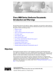
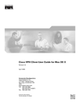
Figure 1-1
Cisco AS5350 Front Panel
35663
3
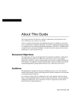
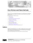
Cisco AS5350 Rear Panel
35665
Figure 1-2
Dial Feature Cards (DFCs)
The Dial Feature Card (DFC) is a 5.1 by 13 inch PCI-based interface board that allows online insertion
and removal (OIR) of trunk ingress, and modem cards without rebooting or powering off the system.
The chassis includes one backplane slot which accepts a DFC carrier card. The DFC carrier card accepts
two DFCs, which allow OIR. The motherboard accepts one DFC in its own dedicated slot.
Cisco AS5350 Universal Gateway Chassis Installation Guide
1-2
78-10754-03 0A
Chapter 1
Overview
Power Supply
Note
For details on cards, installation, and troubleshooting, see the Cisco AS5350 Universal Gateway Card
Installation Guide. This document is available on the World Wide Web and the documentation CD-ROM
that comes with your universal gateway. (See the “Related Documentation” section on page xii.)
Power Supply
The power system is comprised of a single AC or DC power supply or a redundant AC or DC power
supply. Cooling is provided by two self-contained fans.
Note
The Cisco AS5350 redundant power supply is supported in Cisco IOS Release 12.2(2)XB5 or later.
Each power module is capable of supplying a maximum DC load of 150 watts, and is composed of four
independent output voltages: 3.3V, 5V, 12V, and -12V. AC input units have power factor correction, and
low Total Harmonic Distortion. Power failures are reported through environmental monitoring software.
Check the power at your site to ensure that you are receiving “clean” power (free of spikes and noise).
Install a power conditioner if necessary.
Chassis Specifications
Table 1-1
Chassis Specifications
Description
Specification
Dimensions (H x W x D)
1.73 x 17.5 x 20.5 in. (4.39 x 44.45 x 52.07 cm)
Weight
22 lb maximum (10 kg)
Processor
250 MHz
Operating temperature
32 to 104° F (0 to 40° C)
Operating humidity
5 to 95%, noncondensing
Noise level
55 dB1 @ 3 ft (0.914 m)
Input voltage, AC power supply
Current
Frequency
Power factor
Input AC power
100 to 240 VAC 2; -10%, +6% tolerance
2.0 to 1.0 A; dependent on load
50/60 Hz
0.80 to 0.90
140 to 170W; dependent on load
Input voltage, DC power supply
Maximum input current
Input DCpower
-48/-60 Vdc, -10%, +10% tolerance
3 A (1.5-2.0 A typical)
150 W (maximum)
WAN interface options
T1 and E1 dial feature cards
Serial interfaces (for backhaul
WAN support)
2 serial line interfaces
LAN interface options
2 Fast Ethernet 10/100BASE-T (RJ-45) ports
Cisco AS5350 Universal Gateway Chassis Installation Guide
78-10754-03 0A
1-3
Chapter 1
Overview
Chassis Specifications
Table 1-1
Chassis Specifications (continued)
Description
Specification
Console and auxiliary ports
Asynchronous serial (RJ-45)
Regulatory compliance
See the Regulatory Compliance and Safety
Information document that shipped with your
universal gateway. This document is available on
the World Wide Web and the documentation
CD-ROM that comes with your universal
gateway. (See the “Related Documentation”
section on page xii.)
1. dB = decibels.
2. VAC = volts alternating current.
Cisco AS5350 Universal Gateway Chassis Installation Guide
1-4
78-10754-03 0A
C H A P T E R
2
Preparing to Install the Cisco AS5350 Chassis
This chapter describes the tasks you must perform before you begin to install the Cisco AS5350 and
includes the following sections:
•
Safety Recommendations, page 2-1
•
Required Tools and Equipment, page 2-3
•
Preparing to Connect to a Network, page 2-3
Safety Recommendations
Any device that uses electricity must be handled carefully; follow these guidelines to ensure general
safety:
Warning
•
Keep the chassis area clear and dust-free during and after installation.
•
Put the removed chassis cover in a safe place.
•
Keep tools away from walk areas where you and others could fall over them.
•
Do not wear loose clothing that could get caught in the chassis. Fasten your tie or scarf and roll up
your sleeves.
•
Wear safety glasses if you are working under any conditions that might be hazardous to your eyes.
•
Do not perform any action that creates a potential hazard to people or makes the equipment unsafe.
Ultimate disposal of this product should be handled according to all national laws and regulations.
To see translations of the warnings that appear in the publication, refer to the Regulatory Compliance
and Safety Information document that accompanied this device.
Maintaining Safety with Electricity
Warning
Before working on equipment that is connected to power lines, remove jewelry (including rings,
necklaces, and watches). Metal objects will heat up when connected to power and ground and can
cause serious burns or can weld the metal object to the terminals. To see translations of the warnings
that appear in the publication, refer to the Regulatory Compliance and Safety Information document
that accompanied this device.
Cisco AS5350 Universal Gateway Chassis Installation Guide
78-10754-03 0A
2-1
Chapter 2
Preparing to Install the Cisco AS5350 Chassis
Safety Recommendations
Follow these guidelines when you work on equipment powered by electricity.
•
Locate the emergency power-OFF switch for the room in which you are working. Then, if an
electrical accident occurs, you can act quickly to turn OFF the power.
•
Before working on the system, unplug the power cord.
•
Disconnect all power before doing the following:
– Installing or removing a chassis
– Working near power supplies
Warning
When installing the unit, the ground connection must always be made first and disconnected last. Do
not work alone if potentially hazardous conditions exist. To see translations of the warnings that
appear in this publication, refer to the Regulatory Compliance and Safety Information document that
accompanied this device.
•
Warning
Never assume that power is disconnected from a circuit. Always check.
Read the installation instructions before you connect the system to its power source. To see
translations of the warnings that appear in the publication, refer to the Regulatory Compliance and
Safety Information document that accompanied this device.
•
Look carefully for possible hazards in your work area, such as moist floors, ungrounded power
extension cables, frayed power cords, and missing safety grounds.
•
If an electrical accident occurs, proceed as follows:
– Use caution; do not become a victim yourself.
– Turn OFF power to the system.
– If possible, send another person to get medical aid. Otherwise, assess the condition of the victim
and then call for help.
– Determine if the person needs rescue breathing or external cardiac compressions; then take
appropriate action.
Warning
This product relies on the building’s installation for short-circuit (overcurrent) protection. Ensure that
a fuse or circuit breaker no larger than 120 VAC, 15A U.S. (240 VAC, 10A international) is used on the
phase conductors (all current-carrying conductors). To see translations of the warnings that appear
in the publication, refer to the Regulatory Compliance and Safety Information document that
accompanied this device.
Preventing Electrostatic Discharge Damage
Electrostatic discharge (ESD) can damage equipment and impair electrical circuitry. ESD damage occurs
when electronic components are improperly handled and can result in complete or intermittent failures.
Always follow ESD-prevention procedures when you remove and replace components. Ensure that the
chassis is electrically connected to earth ground. Wear an ESD-preventive wrist strap, ensuring that it
makes good skin contact. Connect the grounding clip to an unpainted surface of the chassis frame to
Cisco AS5350 Universal Gateway Chassis Installation Guide
2-2
78-10754-03 0A
Chapter 2
Preparing to Install the Cisco AS5350 Chassis
Required Tools and Equipment
safely ground unwanted ESD voltages. To guard against ESD damage and shocks, the wrist strap and
cord must operate properly. If no wrist strap is available, ground yourself by touching the metal part of
the chassis.
Caution
For safety, periodically check the resistance value of the antistatic strap, which should be between 1 and
10 megohm (Mohm).
Required Tools and Equipment
The following items are included with the universal gateway:
•
19- and 24-inch rack-mount kits
•
Rubber feet for desktop installation
•
RJ-45-to-DB-9 female DTE adapter (labeled TERMINAL)
•
RJ-45-to-DB-25 female DTE adapter (labeled TERMINAL)
•
RJ-45-to-DB-25 male DCE adapter (labeled MODEM)
•
RJ-45-to-RJ-45 rollover console cable
•
ESD-preventive wrist strap
•
Nylon cable tie
•
Cable tie holder
•
Grounding lug
You might need the following equipment, which is not included:
•
Straight-through RJ-45-to-RJ-45 cable for an Ethernet connection
•
Up to two straight-through RJ-45-to-RJ-45 cables for T1 connections
•
Up to two E1 cables for E1 connections
•
Ethernet hub or PC with a network interface card for Ethernet LAN connections
•
PC running terminal emulation software for local administrative access
•
Modem for remote administrative access
Preparing to Connect to a Network
When you set up your universal gateway, consider distance limitations and potential electromagnetic
interference (EMI) as defined by the Electronic Industries Association (EIA).
Warning
Hazardous network voltages are present in WAN ports regardless of whether power to the router is
OFF or ON. To avoid electric shock, use caution when working near WAN ports. When detaching
cables, detach the end away from the router first. To see translations of the warnings that appear in
the publication, refer to the Regulatory Compliance and Safety Information document that
accompanied this device.
Cisco AS5350 Universal Gateway Chassis Installation Guide
78-10754-03 0A
2-3
Chapter 2
Preparing to Install the Cisco AS5350 Chassis
Preparing to Connect to a Network
Warning
The ISDN connection is regarded as a source of voltage that should be inaccessible to user contact.
Do not attempt to tamper with or open any public telephone operator (PTO)-provided equipment or
connection hardware. Any hardwired connection (other than by a nonremovable,
connect-one-time-only plug) must be made only by PTO staff or suitably trained engineers. To see
translations of the warnings that appear in the publication, refer to the Regulatory Compliance and
Safety Information document that accompanied this device.
Ethernet Connections
Two Fast Ethernet (FE) ports, RJ-45 ports, are located on the rear panel of the universal gateway: FE0
and FE1 (selectable). To configure the Ethernet ports, refer to the Cisco AS5350 and Cisco AS5400
Universal Gateway Software Configuration Guide. Both ports use unshielded twisted-pair (UTP) cable
and require Category 5 cable. The maximum segment distance is 328 feet (100 meters).
Note
UTP cables look like the cables used for ordinary telephones; however, UTP cables meet certain
electrical standards that telephone cables do not. Cables are not included.
Console and Auxiliary Ports
The Cisco AS5350 includes an asynchronous serial console port and an auxiliary port. The console and
auxiliary ports provide access to the universal gateway either locally (with a console terminal) or
remotely (with a modem). This section discusses important cabling information to consider before
connecting a console terminal (an ASCII terminal or PC running terminal emulation software) to the
console port, or modem to the auxiliary port.
Console Port
The Cisco AS5350 includes an EIA/TIA-232 asynchronous serial console port (RJ-45). Depending on
the cable and the adapter used, this port will appear as a data terminal equipment (DTE) or data
communications equipment (DCE) device at the end of the cable. Your universal gateway arrives with
cables and adapters to connect a console terminal (an ASCII terminal or PC running terminal emulation
software) to the console port. To connect an ASCII terminal to the console port, use the RJ-45 rollover
cable with the female RJ-45-to-DB-25 adapter (labeled TERMINAL).
To connect a PC running terminal emulation software to the console port, use the RJ-45 rollover cable
with the female RJ-45-to-DB-9 adapter (labeled TERMINAL). The default parameters for the console
port are 9600 baud, 8 data bits, no parity, and 2 stop bits. The console port does not support hardware
flow control.
For detailed information about installing a console terminal, see Chapter 3, “Installing the
Cisco AS5350.” See Appendix C, “Cabling Specifications,” for cable and port pinouts.
Cisco AS5350 Universal Gateway Chassis Installation Guide
2-4
78-10754-03 0A
Chapter 2
Preparing to Install the Cisco AS5350 Chassis
Preparing to Connect to a Network
Auxiliary Port
The Cisco AS5350 includes an EIA/TIA-232 asynchronous serial auxiliary port (RJ-45) that supports
flow control. Depending on the cable and the adapter used, this port will appear as a DTE or DCE device
at the end of the cable. Your universal gateway arrives with a cable and an adapter to connect a modem
to the auxiliary port. To connect a modem to the auxiliary port, use the RJ-45 rollover cable with the
male RJ-45-to-DB-25 adapter (labeled MODEM).
For detailed information about connecting devices to the auxiliary port, see Chapter 3, “Installing the
Cisco AS5350.” See Appendix C, “Cabling Specifications,” for cable and port pinouts.
2T Serial Ports
Two high speed 12-in-1 serial ports on the rear panel of the Cisco AS5350 provide backhaul WAN and
IP support.
The following types of serial interface standards (in DTE/DCE) are supported:
•
EIA/TIA-232
•
EIA/TIA-449
•
EIA/TIA-530
•
EIA/TIA-530A
•
EIA/TIA-X.21
•
ITU-T V.35
Each interface supports up to 8 Mbps.
Alarm Port
The three pins on the alarm port are connected to the output of a relay. This relay is controlled by system
software. To configure the Alarm port, refer to the Cisco AS5350 and Cisco AS5400 Universal Gateway
Software Configuration Guide. This document is available on CCO and the documentation CD-ROM
that comes with your universal gateway. (See the “Related Documentation” section on page xii.) With
the alarm ports connected and configured, Cisco IOS software polls every one second to detect the
failure events that are configured and turns ON the alarm when it detects any failure event. See
Appendix C, “Cabling Specifications,” for pinouts and cable specifications.
BITS Port
The BITS port is a coaxial interface that provides external synchronized clocking through a Timing
Signal Generator (TSG). To configure the BITS port, refer to the Cisco AS5350 and Cisco AS5400
Universal Gateway Software Configuration Guide. This document is available on CCO and the
documentation CD-ROM that comes with your universal gateway. (See the “Related Documentation”
section on page xii.) See Appendix C, “Cabling Specifications,” for pinouts and cable specifications.
Cisco AS5350 Universal Gateway Chassis Installation Guide
78-10754-03 0A
2-5
Chapter 2
Preparing to Install the Cisco AS5350 Chassis
Preparing to Connect to a Network
Power Supply Considerations
Check the power at your site to ensure that you are receiving “clean” power (free of spikes and noise).
Install a power conditioner if necessary.
Warning
The device is designed to work with TN power systems. To see translations of the warnings that
appear in the publication, refer to the Regulatory Compliance and Safety Information document that
accompanied this device.
Warning
This product relies on the building’s installation for short-circuit (overcurrent) protection. Ensure that
a fuse or circuit breaker no larger than 120 VAC, 15A U.S. (240 VAC, 10A international) is used on the
phase conductors (all current-carrying conductors). To see translations of the warnings that appear
in the publication, refer to the Regulatory Compliance and Safety Information document that
accompanied this device.
The universal gateway AC power supply includes the following features:
•
Full range operation—100 to 240 VAC.
•
All units include a 6-foot (1.8-m) electrical power cord. (A label near the power inlet indicates the
correct voltage, frequency, and current draw for the unit.)
Note
The redundant AC power supply has a power cord with a special connector.
The universal gateway DC power supply includes the following features:
•
150 W output
•
Dual input connections for power source redundancy
•
Removable DC connector (A label near the power inlets indicates the correct voltage, current draw,
and power dissipation for the unit.)
•
Double-hole grounding lug for reliable grounding to the chassis
Cisco AS5350 Universal Gateway Chassis Installation Guide
2-6
78-10754-03 0A
C H A P T E R
3
Installing the Cisco AS5350
This chapter guides you through the installation of the Cisco AS5350 universal gateway and includes the
following sections:
•
Setting Up the Chassis, page 3-2
•
Connecting to the Network, page 3-6
•
Connecting to the Console and Auxiliary Ports, page 3-11
•
Connecting a Signal Generator to the BITS Port, page 3-13
•
Connecting an Alarm to the Alarm Port, page 3-14
•
Supplying Power, page 3-15
•
Where to Go Next, page 3-19
Warning
Only trained and qualified personnel should be allowed to install or replace this equipment. To see
translations of the warnings that appear in the publication, refer to the Regulatory Compliance and
Safety Information document that accompanied this device.
Warning
This equipment is intended to be grounded. Ensure that the host is connected to earth ground during
normal use. To see translations of the warnings that appear in the publication, refer to the Regulatory
Compliance and Safety Information document that accompanied this device.
Warning
Incorrect connection of this or connected equipment to the general purpose outlet could result in a
hazardous situation. To see translations of the warnings that appear in the publication, refer to the
Regulatory Compliance and Safety Information document that accompanied this device.
Cisco AS5350 Universal Gateway Chassis Installation Guide
78-10754-03 0A
3-1
Chapter 3
Installing the Cisco AS5350
Setting Up the Chassis
Setting Up the Chassis
You can set the chassis on a desktop or install it in a rack. Use the procedure in this section that best
meets the needs of your network:
•
Setting the Chassis on a Desktop
•
Rack-Mounting the Chassis
Warning
When installing the unit, the ground connection must always be made first and disconnected last. To
see translations of the warnings that appear in the publication, refer to the Regulatory Compliance
and Safety Information document that accompanied this device.
Warning
This unit is intended for installation in restricted access areas. A restricted access area is where
access can only be gained by service personnel through the use of a special tool, lock and key, or
other means of security, and is controlled by the authority responsible for the location. To see
translations of the warnings that appear in the publication, refer to the Regulatory Compliance and
Safety Information document that accompanied this device.
Setting the Chassis on a Desktop
The location of the chassis is extremely important for proper operation. Equipment placed too close
together, inadequate ventilation, and inaccessible panels can cause malfunctions and shutdowns, and can
make maintenance difficult. The following information will help you plan the location of the chassis:
•
Plan for access to both front and rear panels of the chassis.
•
Ensure that the room where the chassis operates has adequate ventilation. Remember that electrical
equipment generates heat. Ambient air temperature may not cool equipment to acceptable operating
temperatures without adequate ventilation.
Attaching the Rubber Feet
To attach the rubber feet to the chassis, follow this procedure:
Step 1
Carefully turn the chassis over so you can see the four small depressions made for attaching the rubber
feet. (See Figure 3-1.) The rubber feet are included in the accessory kit that shipped with your universal
gateway.
Step 2
Remove the wax paper from the bottom of each rubber foot and press the foot into the small depression
on the bottom of the chassis. (See Figure 3-1.)
Cisco AS5350 Universal Gateway Chassis Installation Guide
3-2
78-10754-03 0A
Chapter 3
Installing the Cisco AS5350
Setting Up the Chassis
Attaching the Rubber Feet
37208
Figure 3-1
Universal gateway
chassis bottom
Rack-Mounting the Chassis
This section describes how to rack-mount the chassis. The universal gateway arrives with 19-inch
rack-mount brackets and larger brackets for use with a 23- or 24-inch rack (See Figure 3-2).
The following information will help you plan your equipment rack configuration:
Warning
•
Enclosed racks must have adequate ventilation. Ensure that the rack is not congested, because each
unit generates heat. An enclosed rack should have louvered sides and a fan to provide cooling air.
Heat generated by equipment near the bottom of the rack can be drawn upward into the intake ports
of the equipment above.
•
When mounting a chassis in an open rack, ensure that the rack frame does not block the intake or
exhaust ports. If the chassis is installed on slides, check the position of the chassis when it is seated
in the rack.
•
Baffles can isolate exhaust air from intake air, which also helps to draw cooling air through the
chassis. The best placement of the baffles depends on the airflow patterns in the rack, which can be
found by experimenting with different configurations.
Before working on a chassis or working near power supplies, unplug the power cord on AC units;
disconnect the power at the circuit breaker on DC units. To see translations of the warnings that
appear in the publication, refer to the Regulatory Compliance and Safety Information document that
accompanied this device.
Cisco AS5350 Universal Gateway Chassis Installation Guide
78-10754-03 0A
3-3
Chapter 3
Installing the Cisco AS5350
Setting Up the Chassis
Required Tools and Equipment
You need the following tools and equipment to rack-mount the chassis:
•
Number 2 Phillips screwdriver (not included)
•
Medium flat-blade screwdriver (not included)
•
Screws for attaching the chassis to the rack (not included)
•
Standard rack-mount brackets (included)
•
Screws for attaching the brackets to the chassis (included)
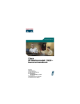
Standard Rack-Mount Brackets
Bracket for 19-inch rack
Bracket for 23-inch rack
36012
Figure 3-2
Attaching the Brackets
To attach the mounting brackets to the chassis, follow this procedure:
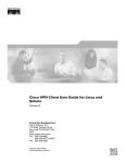
Step 1
Set the chassis on a flat surface. (See Figure 3-3.)
Note
Step 2
The chassis may be installed with either the front or rear panel facing forward.
Attach the standard 19 or 23-inch rack brackets to the sides of the chassis. Use the screws provided with
the mounting brackets. (See Figure 3-3.)
Note
There are three sets of mounting holes on the sides of the chassis. Attach the brackets for front,
rear, or middle mounting.
Standard Bracket Installation—Front Panel Forward
35669
Figure 3-3
Note: The second bracket attaches to the other side of the chassis.
The chassis can also be installed with the rear panel forward.
Cisco AS5350 Universal Gateway Chassis Installation Guide
3-4
78-10754-03 0A
Chapter 3
Installing the Cisco AS5350
Setting Up the Chassis
Installing in a Rack
Caution
Do not use the handles on the dial feature cards to assist in lifting the chassis.
To install the chassis into the equipment rack, follow this procedure:
Step 1
With the mounting brackets attached to the chassis, support the chassis and align the holes in the brackets
with the screw holes in the rack. (See Figure 3-4.)
Step 2
Attach the chassis to the rack with the screws you have provided. (See Figure 3-4.)
Attaching the Chassis to a 19-Inch Rack—Rear Panel Forward
35659
Figure 3-4
Note: The second bracket attaches to the rack at the other side
of the chassis. The chassis can also be installed with the
front panel forward.
Connecting the Chassis Ground
You must connect the chassis to a reliable earth ground using the ground lug (provided) and size AWG 6
(13 mm2) wire.
To attach the chassis ground, take the following steps:
Step 1
Strip one end of the ground wire to expose approximately 0.75 in. (20 mm) of conductor.
Step 2
Crimp the ground wire to the ground lug, using a crimp tool of the appropriate size.
Step 3
Attach the ground lug to the chassis. (See Figure 3-5 or Figure 3-6.) Use a medium flat-blade
screwdriver and the screws supplied with the ground lug. Tighten the screws to a torque of 8 to 10 in-lb
(0.9 to 1.1 N-m).
Step 4
Connect the other end of the ground wire to a suitable grounding point at your site.
Cisco AS5350 Universal Gateway Chassis Installation Guide
78-10754-03 0A
3-5
Chapter 3
Installing the Cisco AS5350
Connecting to the Network
Cisco AS5350 Ground Lug Attachment
82735
Figure 3-5
Ground lug
attachment
Cisco AS5400 Ground Lug Attachment
82734
Figure 3-6
Ground lug
attachment
Connecting to the Network
This section describes how to connect the Cisco AS5350 to your network. The cables required to connect
the universal gateway to a network are not provided. For ordering information, contact customer service.
See the “Obtaining Technical Assistance” section on page xiv, or see Appendix C, “Cabling
Specifications,” for cable and port pinouts.
Warning
To avoid electric shock, do not connect safety extra-low voltage (SELV) circuits to telephone-network
voltage (TNV) circuits. LAN ports contain SELV circuits, and WAN ports contain TNV circuits. Some
LAN and WAN ports use both RJ-45 connectors. Use caution when connecting cables. To see
translations of the warnings that appear in the publication, refer to the Regulatory Compliance and
Safety Information document that accompanied this device.
Warning
Do not work on the system or connect or disconnect cables during periods of lightning activity. To see
translations of the warnings that appear in the publication, refer to the Regulatory Compliance and
Safety Information document that accompanied this device.
Cisco AS5350 Universal Gateway Chassis Installation Guide
3-6
78-10754-03 0A
Chapter 3
Installing the Cisco AS5350
Connecting to the Network
Caution
If the universal gateway is configured with fewer than three DFCs, make sure that a blank slot cover is
installed over each open slot to ensure proper airflow.
Note
The Cisco AS5350 arrives with all carrier cards and DFCs already installed, unless you order a card
separately as a spare. Refer to the Cisco AS5350 Universal Gateway Card Installation Guide for card
installation instructions. This document is available on Cisco.com and the documentation CD-ROM that
comes with your universal gateway. (See the “Obtaining Documentation” section on page xiii.)
Connecting to an Ethernet Network
Connect an Cisco AS5350 Fast Ethernet port to an Ethernet hub using a straight-through,
RJ-45-to-RJ-45, Ethernet cable. (See Figure 3-7.)
Figure 3-7
Connecting to an Ethernet Hub (10/100BASE-T Shown)
FE1
10/100BASE-T port
(RJ-45)
Ethernet hub
8
7
35670
1
Straight-through
Ethernet cable
Connecting to a WAN
Warning
To reduce the risk of fire, use only No. 26 AWG or larger telecommunication line cord. To see
translations of the warnings that appear in the publication, refer to the Regulatory Compliance and
Safety Information document that accompanied this device.
Warning
This equipment is to be installed and maintained by service personnel only as defined by AS/NZS 3260
Clause 1.2.14.3 Service Personnel. To see translations of the warnings that appear in the publication,
refer to the Regulatory Compliance and Safety Information document that accompanied this device.
Cisco AS5350 Universal Gateway Chassis Installation Guide
78-10754-03 0A
3-7
Chapter 3
Installing the Cisco AS5350
Connecting to the Network
Warning
Hazardous network voltages are present in WAN ports regardless of whether power to the router is
OFF or ON. To avoid electric shock, use caution when working near WAN ports. When detaching
cables, detach the end away from the router first. To see translations of the warnings that appear in
the publication, refer to the Regulatory Compliance and Safety Information document that
accompanied this device.
Warning
The telecommunications lines must be disconnected 1) before unplugging the main power connector
and/or 2) while the housing is open. To see translations of the warnings that appear in the publication,
refer to the Regulatory Compliance and Safety Information document that accompanied this device.
You can connect the Cisco AS5350 to a WAN in the following ways:
Connect each T1/PRI port to an RJ-45 jack with a straight-through RJ-45 to RJ-45 cable. (See
Figure 3-8 and Figure 3-9.)
Figure 3-8
Connecting a 2-Port or 4-Port DFC to an RJ-45 (T1) Jack
Straight-through
RJ-45-to-RJ-45 cable
RJ-45 jack
35672
•
Cisco AS5350 Universal Gateway Chassis Installation Guide
3-8
78-10754-03 0A
Chapter 3
Installing the Cisco AS5350
Connecting to the Network
Connecting an 8-Port DFC to a RJ-45 (T1) Jack
P
0
P
1
P
2
P
3
P
4
P
5
P
6
P
7
56057
Figure 3-9
T1/E1 8 PRI
connector
Straight-through
RJ-45-to-RJ-45 cable
Note
Use software commands to choose a specific port and the line termination on that port. For information
on software commands, see the Cisco AS5350 and Cisco AS5400 Universal Gateway Software
Configuration Guide. This document is available on the Cisco.com and the documentation CD-ROM that
comes with your universal gateway. (See the “Obtaining Documentation” section on page xiii.) If you
choose a port with 75-ohm input impedance, use an RJ-45-to-75-ohm coaxial cable adapter and plug it
into that port.
•
Warning
RJ-45 jack
Connect each E1/PRI port to an RJ-45 jack with a straight-through RJ-45 to RJ-45 cable. (See
Figure 3-10 and Figure 3-11.)
The E1 interface card may only be installed in an ACA-permitted customer equipment or a Data
Terminal Equipment (DTE) that is exempted from ACA’s permit requirements. The customer equipment
must only be housed in a cabinet that has screw-down lids to stop user access to overvoltages on the
customer equipment. The customer equipment has circuitry that may have telecommunications
network voltages on them. To see translations of the warnings that appear in the publication, refer to
the Regulatory Compliance and Safety Information document that accompanied this device.
Cisco AS5350 Universal Gateway Chassis Installation Guide
78-10754-03 0A
3-9
Chapter 3
Installing the Cisco AS5350
Connecting to the Network
35673
Figure 3-10 Connecting a 2-Port or 4-Port DFC to an RJ-45 Jack
RJ-45 jack
E1 cable
P
0
P
1
P
2
P
3
P
4
P
5
P
6
P
7
56058
Figure 3-11 Connecting an 8-Port DFC to an RJ-45 Jack
T1/E1 8 PRI
connector
E1 cable
RJ-45 jack
Cisco AS5350 Universal Gateway Chassis Installation Guide
3-10
78-10754-03 0A
Chapter 3
Installing the Cisco AS5350
Connecting to the Console and Auxiliary Ports
•
Connect a synchronous serial port to a modem or a CSU/DSU with a serial transition cable. (See
Figure 3-12.)
35675
Figure 3-12 Connecting to a CSU/DSU
Synchronous serial
port (DB-26)
Internet
CSU/DSU or
other DCE or DTE
Serial
transition
cable
EIA/TIA-232, EIA/TIA-449, EIA/TIA-530A,
EIA/TIA-530, V.35, or X.21 connector
Connecting to the Console and Auxiliary Ports
Use the console terminal for local administrative access to the universal gateway. You can only connect
a terminal to the console port. You can use the auxiliary port to connect a terminal or a modem for remote
access to the universal gateway.
Connecting to the Console Port
To connect a terminal (an ASCII terminal or a PC running terminal emulation software) to the console
port on the Cisco AS5350, follow this procedure:
Step 1
Connect the terminal to the console port using an RJ-45 rollover cable and an RJ-45-to-DB-25 or
RJ-45-to-DB-9 adapter. The adapters provided are labeled TERMINAL. The adapters and the rollover
cable are included in the accessory kit that comes with the universal gateway. (See Figure 3-13.)
Note
For additional information on rollover cable pinouts, see Appendix C, “Cabling Specifications.”
Step 2
Configure your terminal or PC terminal emulation software for 9600 baud, 8 data bits, no parity, and
2 stop bits.
Step 3
Configure the console port. See the Cisco AS5350 and Cisco AS5400 Universal Gateway Software
Configuration Guide. This document is available on the World Wide Web and the documentation
CD-ROM that comes with your universal gateway. (See the “Obtaining Documentation” section on
page xiii.)
Cisco AS5350 Universal Gateway Chassis Installation Guide
78-10754-03 0A
3-11
Chapter 3
Installing the Cisco AS5350
Connecting to the Console and Auxiliary Ports
Figure 3-13 Connecting the Console Terminal
35676
Console port
(RJ-45)
RJ-45-to-RJ-45
rollover cable
PC (laptop)
RJ-45
Connecting a Modem to the Auxiliary Port
To connect a modem to the auxiliary port, follow this procedure:
Step 1
Connect a modem to the auxiliary port on the Cisco AS5350 using an RJ-45 rollover cable with an
RJ-45-to-DB-25 adapter. The adapter provided is labeled MODEM. The adapter and the rollover cable
are included in the accessory kit that comes with the universal gateway.(See Figure 3-14.)
Note
Make sure that your modem and the auxiliary port on the Cisco AS5350 are configured for the
same transmission speed (38400 baud is typical) and hardware flow control with Data Carrier
Detect (DCD) and Data Terminal Ready (DTR) operations.
Cisco AS5350 Universal Gateway Chassis Installation Guide
3-12
78-10754-03 0A
Chapter 3
Installing the Cisco AS5350
Connecting a Signal Generator to the BITS Port
Figure 3-14 Connecting a Modem to the Auxiliary Port
Modem
35677
RJ-45-to-RJ-45
rollover cable
Auxiliary port
(RJ-45)
RJ-45-to-DB-25 adapter
(labeled MODEM)
Connecting a Signal Generator to the BITS Port
Use a coaxial cable to connect a Timing Signal Generator (TSG) to the BITS port. The BITS port is used
for external clocking. (See Figure 3-15.)
35841
Figure 3-15 Connecting to the BITS Port
To timing signal
generator
Coaxial cable
BITS port
connector
Cisco AS5350 Universal Gateway Chassis Installation Guide
78-10754-03 0A
3-13
Chapter 3
Installing the Cisco AS5350
Connecting an Alarm to the Alarm Port
Connecting an Alarm to the Alarm Port
To connect an alarm device to the alarm port, follow this procedure:
Note
The alarm connector is a 3-wire connector that plugs into a receptacle in the rear of the chassis. The
connector is provided in the accessory kit that ships with the Cisco AS5350.
Step 1
Insert the three pin alarm port connector (included in the accessory kit) into the alarm port terminal
block.
Step 2
Strip a minimum 1/4 in. (0.625 cm) off the wire insulation to connect the stranded wires to the alarm
connector. The maximum insulation strip length is 0.31 in. (0.78 cm).
Note
Step 3
Caution
Connect the alarm port only to a safety extra-low voltage (SELV) source using 22 AWG, or
thicker, copper wire. SELV ratings are maximum 30 Volts AC (RMS), maximum 60 Volts DC,
and maximum 50 VA power. The alarm port is rated for 2.0 Amp maximum current.
Secure the wires to the alarm connector with the screws on the connector. See Appendix C, “Cabling
Specifications,” for alarm port pinouts.
The maximum tightening torque on the screws is 7 in.-lb (0.79 N-m).
Step 4
Attach two cable ties to the chassis and connect the wires to the cable ties. (See Figure 3-16.)
Step 5
Attach the alarm wires to the alarm device.
Figure 3-16 Connecting to the Alarm Port
To alarm device
Cable ties
#1
#3
#2
35967
Alarm port
connector
Cisco AS5350 Universal Gateway Chassis Installation Guide
3-14
78-10754-03 0A
Chapter 3
Installing the Cisco AS5350
Supplying Power
Supplying Power
The power system comprises an AC or DC power supply or a redundant AC or DC power supply, with
internal cooling provided by two self-contained fans.
Note
The redundant power supply is supported in Cisco IOS Release 12.2(2)XB5 or later releases.
Each power module is capable of supplying a maximum DC load of 150 watts, and is composed of four
independent output voltages: 3.3V, 5V, 12V, and -12V. AC input units have power factor correction, and
low Total Harmonic Distortion. Power failures are reported through environmental monitoring software.
Check the power at your site to ensure that you are receiving “clean” power (free of spikes and noise).
Install a power conditioner if necessary.
The universal gateway AC power supply includes the following features:
•
Full range operation—100 to 240 VAC.
•
All AC units include a 6-foot (1.8-meter) electrical power cord (A label near the power inlets
indicates the correct voltage, frequency, current draw, and power dissipation for the unit.)
Note
The redundant AC power supply has a non-standard connector. Use the electrical power cord that
came with your universal gateway.
The universal gateway DC power supply includes the following features:
•
150 W output
•
Dual input connections for power source redundancy
•
Removable DC connector (A label near the power inlets indicates the correct voltage, current draw,
and power dissipation for the unit.)
•
Double-hole grounding lug for reliable grounding to the chassis
Follow this procedure to connect power to the universal gateway:
Step 1
Connect one end of the AC power cord to the power connector on the rear panel of the Cisco AS5350 (See
Figure 3-17 or Figure 3-18.) Or, if you are using a DC-powered unit, refer to Figure 3-19 or Figure 3-20,
and complete Step a through Step e.
Step 2
Connect the other end of the AC power cord to the power outlet.
Warning
This product relies on the building’s installation for short-circuit (overcurrent) protection. Ensure that
a fuse or circuit breaker no larger than 120 VAC, 15A U.S. (240 VAC, 10A international) is used on the
phase conductors (all current-carrying conductors). To see translations of the warnings that appear
in the publication, refer to the Regulatory Compliance and Safety Information document that
accompanied this device.
Warning
The device is designed to work with TN power systems. To see translations of the warnings that appear in
the publication, refer to the Regulatory Compliance and Safety Information document that accompanied this
device.
Cisco AS5350 Universal Gateway Chassis Installation Guide
78-10754-03 0A
3-15
Chapter 3
Installing the Cisco AS5350
Supplying Power
Warning
The plug-socket combination must be accessible at all times because it serves as the main
disconnecting device.To see translations of the warnings that appear in the publication, refer to the
Regulatory Compliance and Safety Information document that accompanied this device.
35678
Figure 3-17 Connecting the AC Power Cord
Power switch
82079
Figure 3-18 Connecting the AC Power Cord to the Redundant Power Supply
Power cables
Warning
Before performing any of the following procedures, ensure that power is removed from the DC circuit.
To ensure that all power is OFF, locate the circuit breaker on the panel board that services the DC
circuit, switch the circuit breaker to the OFF position, and tape the switch handle of the circuit
breaker in the OFF position. To see translations of the warnings that appear in this publication, refer
to the Regulatory Compliance and Safety Information document that accompanied this device.
Cisco AS5350 Universal Gateway Chassis Installation Guide
3-16
78-10754-03 0A
Chapter 3
Installing the Cisco AS5350
Supplying Power
Warning
The illustration shows the DC power supply terminal block. Wire the DC power supply using the
appropriate wire terminations at the wiring end, as illustrated. The proper wiring sequence is ground
to ground, return to return, and negative to negative. Note that the ground wire should always be
connected first and disconnected last. To see translations of the warnings that appear in this
publication, refer to the Regulatory Compliance and Safety Information document that accompanied
this device.
Figure 3-19 DC Power Supply Connections—Single Power Supply
Power switch
To DC source
56022
DC connector
Source A - NEG
Ground
Source B - RTN
Source A - RTN
Source B - NEG
Caution
Do not overtorque the terminal block contact screws. The recommended torque is 4.5 lb-in (0.50 N-m).
Cisco AS5350 Universal Gateway Chassis Installation Guide
78-10754-03 0A
3-17
Chapter 3
Installing the Cisco AS5350
Supplying Power
Figure 3-20 DC Power Supply Connections—Redundant Power Supply
To DC source
Power switch
A- A+ B- B+
82637
DC connector
Ground
Source A - NEG
Source B - RTN
Source A - RTN
Source B - NEG
Note
This product is intended for installation in restricted access areas and is approved for connection
using 12 or 14 AWG copper conductors only. The installation must comply with all applicable
codes.
Note
If you are installing a redundant power supply, you should attach appropriate sized spade
terminals to the stripped ends of the ground and input wires.
a.
Strip off a quarter of an inch (1/4 in. [0.625 cm]) of insulation on the safety ground, +48 VDC, and
-48 VDC input wires.
b.
Insert the safety ground (green wire) into the DC connector ground connector and tighten the
locking screws. Ensure that no bare wire is exposed.
c.
Insert the 48 VDC Return wires into the DC connector positive connectors (+) and tighten the
locking screws. Ensure that no bare wire is exposed.
d.
Insert the -48 VDC wires into the DC connector negative connectors (-) and tighten the locking
screws. Ensure that no bare wire is exposed.
e.
Make sure that the power supply wires are secured to cable strain-relief clamps with cable ties.
Cisco AS5350 Universal Gateway Chassis Installation Guide
3-18
78-10754-03 0A
Chapter 3
Installing the Cisco AS5350
Where to Go Next
Warning
Step 3
After wiring the DC power supply, remove the tape from the circuit breaker switch handle and
reinstate power by moving the handle of the circuit breaker to the ON position. To see translations of
the warnings that appear in this publication, refer to the Regulatory Compliance and Safety
Information document that accompanied this device.
Power on the universal gateway.
The internal power supply fan should power on.
Where to Go Next
When you power ON the Cisco AS5350 for the first time, messages will begin to appear on your console
screen. Refer to the Cisco AS5350 and Cisco AS5400 Universal Gateway Software Configuration Guide
for configuration instructions. This document is available on the World Wide Web and the
documentation CD-ROM that comes with your Cisco AS5350. (See the “Obtaining Documentation”
section on page xiii.)
The remaining chapters of this guide include reference material for replacing spare parts,
troubleshooting, and creating your own cables:
•
Chapter 4, “Troubleshooting”
•
Appendix A, “Replacing Memory Components”
•
Appendix B, “Replacing the Power Supply”
•
Appendix C, “Cabling Specifications”
Cisco AS5350 Universal Gateway Chassis Installation Guide
78-10754-03 0A
3-19
Chapter 3
Installing the Cisco AS5350
Where to Go Next
Cisco AS5350 Universal Gateway Chassis Installation Guide
3-20
78-10754-03 0A
C H A P T E R
4
Troubleshooting
This chapter describes troubleshooting techniques for the Cisco AS5350. The chapter contains the
following sections:
•
LEDs, page 4-1
•
Monitoring Environment, page 4-3
•
Troubleshooting Network Interfaces, page 4-6
•
Replacing the Fan Tray, page 4-6
•
Getting Help, page 4-12
LEDs
The LEDs indicate the current operating condition of the Cisco AS5350. You can observe the LEDs, note
any fault condition that the product is encountering, and then contact your system administrator or a
customer service representative (see the “Obtaining Technical Assistance” section on page xiv), if
necessary. Refer to Figure 4-1 for a diagram illustrating the rear panel LEDs and Table 4-1 for a
description of the LEDs.
For information about LEDs and troubleshooting on Cisco AS5350 dial feature cards, see the
Cisco AS5350 Universal Gateway Card Installation Guide. This document is available on the World
Wide Web and the documentation CD-ROM that comes with your universal gateway. (See the “Obtaining
Documentation” section on page xiii.)
Cisco AS5350 Universal Gateway Chassis Installation Guide
78-10754-03 0A
4-1
Chapter 4
Troubleshooting
LEDs
Figure 4-1
Rear Panel LEDs
T0
BITS
T1
LNK
BOARD OK
LED
ACTIVITY (ACT)
LNK
35679
ACTIVITY (ACT)
Table 4-1
Chassis LEDs
Function
LED
State
Description
Alarm
Alarm
On
An alarm error is detected.
Fast Ethernet
Activity (ACT)
Flickering
The Fast Ethernet LAN connection
is transmitting and receiving data
normally.
Off
The Fast Ethernet LAN connection
is not transmitting or receiving data.
On
Fast Ethernet cable is connected
properly.
Off
The Fast Ethernet port is not
connected.
Flickering
The console or auxiliary connection
is transmitting and receiving data
normally.
Off
The console or auxiliary connection
is not transmitting or receiving data.
On
The console or auxiliary cable is
connected properly.
Off
The console or auxiliary port is not
connected.
On
System board is operating normally.
Off
Power is off or system has not
booted.
Blinking
A memory failure occurred.
Link (LNK)
Console/Auxiliary
Activity (ACT)
Link (LNK)
System Board Status
(Located to right of
Console/Auxiliary ports)
OK
Cisco AS5350 Universal Gateway Chassis Installation Guide
4-2
78-10754-03 0A
Chapter 4
Troubleshooting
Monitoring Environment
Table 4-1
Chassis LEDs (continued)
Function
LED
State
Description
Serial Ports
T0, T1
Flickering
Indicates data activity on the serial
ports.
Off
The serial port connection is not
transmitting or receiving data.
ON
Indicates a valid signal on the BITS
port.
BITS Port
BITS
Monitoring Environment
The Cisco AS5350 contains temperature sensors to detect abnormal temperature conditions during
system operation. The three levels of sensor detection are as follows:
•
If the operating temperature of the system exceeds 45° C, the system reaches a warning state. A
warning message appears on the console. When the operating temperature of the system drops below
45° C, another message is displayed on the console indicating a recovery. At this level of sensor
detection, there is no disruption in system operation.
•
When the operating temperature of the system continues to rise above 45° C and reaches a
temperature of 60° C, the system reaches a critical state. Cisco IOS software gracefully shuts down
the first DFC. If the operating temperature continues to be critical after 10 minutes, Cisco IOS
software shuts down another DFC.
Note
DFC slot numbering starts from the motherboard and works up from left to right. Slot 0 is
reserved for the motherboard. The DFC slots are numbered sequentially from 1 to 3. (See
Figure 4-2.)
Cisco AS5350 Slot Numbering
Slot 2
Slot 0
36006
Figure 4-2
Slot 1
Slot 3
This process is repeated at 10 minute intervals until the final DFC is shut down. The console displays
the slot number of the DFC and the type of DFC that was shut down.
If the operating temperature cools down to 45° C, Cisco IOS software powers on the first DFC,
repeating the process for each DFC at 10 minute intervals.
•
When the operating temperature of the system rises above 65° C, Cisco IOS software shuts down all
DFCs immediately.
Cisco AS5350 Universal Gateway Chassis Installation Guide
78-10754-03 0A
4-3
Chapter 4
Troubleshooting
Monitoring Environment
Displaying Environment Status
You can use the command-line interface (CLI) to check environment monitoring status of the
Cisco AS5350.
To check environment monitoring, enter the show environment command in privileged EXEC mode, as
follows:
Router# show environment
The display shown below appears on your console during normal operating conditions. The slot number
corresponds to the DFC in that slot. The outlet and inlet sensors read the temperature of the air
circulating inside the chassis.
Router# show environment
Temperature:
Temperature Reading:
Temperature at inlet is measured as 22C/71F.
Temperature at outlet is measured as 27C/80F.
Temperature State:
Temperature is in normal state.
Fans:
Fans temperature delta is measured as 5C.
All fans are running well.
Power Supply:
Power System is present.
The display below appears on your console when the system reaches a warning state:
Router# show environment
Temperature:
Temperature Reading:
Temperature at inlet is measured as 52C/125F.
Temperature at outlet is measured as 64C/147F.
Temperature State:
Temperature is in warning state.
Fans:
Fans temperature delta is measured as 6C.
All fans are running well.
Power Supply:
Power System is not present.
PS Input Voltage status: normal
PS Output Voltage status: normal
PS Fan status: normal
PS Thermal status: normal
PS OverVoltage status: normal
Environmental monitor experienced the following events:
Temperature:sensor failed.
Fans:monitor dropped.
Temperature:warning.
Temperature:sensor recovered.
Fans:monitor recovered.
Fans:normal.
Cisco AS5350 Universal Gateway Chassis Installation Guide
4-4
78-10754-03 0A
Chapter 4
Troubleshooting
Monitoring Environment
The display below appears on your console when the system reaches a critical state:
Router# show environment
Temperature:
Temperature Reading:
Temperature at inlet is measured as 62C/143F.
Temperature at outlet is measured as 74C/165F.
Temperature State:
Temperature is in critical state.
DFC Busyout/Power-down:
A DFC is powered down. Slot:1, Type:NP60 DFC
A DFC is busyout. Slot:2, Type:T1 2 PRI DFC
A DFC is busyout. Slot:3, Type:NP60 DFC
Fans:
Fans temperature delta is measured as 6C.
All fans are running well.
Power Supply:
Power System is present.
PS Input Voltage status: normal
PS Output Voltage status: normal
PS Fan status: normal
PS Thermal status: normal
PS OverVoltage status: normal
Environmental monitor experienced the following events:
Temperature:sensor failed.
Fans:monitor dropped.
Temperature:warning.
Temperature:sensor recovered.
Fans:monitor recovered.
Fans:normal.
Temperature:critical.
The display below appears on your console when the system reaches a shutdown state:
Router# show environment
Temperature:
Temperature Reading:
Temperature at inlet is measured as 70C/158F.
Temperature at outlet is measured as 82C/179F.
Temperature State:
Temperature is in shutdown state.
DFC Busyout/Power-down:
A DFC is powered down. Slot:1, Type:NP60 DFC
A DFC is powered down. Slot:2, Type:T1 2 PRI DFC
A DFC is powered down. Slot:3, Type:NP60 DFC
Fans:
Fans temperature delta is measured as 6C.
All fans are running well.
Power Supply:
Power System is present.
PS Input Voltage status: normal
PS Output Voltage status: normal
PS Fan status: normal
PS Thermal status: normal
PS OverVoltage status: normal
Cisco AS5350 Universal Gateway Chassis Installation Guide
78-10754-03 0A
4-5
Chapter 4
Troubleshooting
Troubleshooting Network Interfaces
Environmental monitor experienced the following events:
Temperature:sensor failed.
Fans:monitor dropped.
Temperature:warning.
Temperature:sensor recovered.
Fans:monitor recovered.
Fans:normal.
Temperature:critical.
Temperature:shutdown.
Troubleshooting Network Interfaces
For information about isolating problems with the network connections to your Cisco AS5350, refer to
the publication Internetwork Troubleshooting Guide available on the Cisco Documentation CD-ROM.
For more information, see the section “Related Documentation” section on page xii.
Replacing the Fan Tray
Warning
Caution
Before working on a system that has an on/off switch, turn OFF the power and unplug the power
cord.To see translations of the warnings that appear in this publication, refer to the Regulatory
Compliance and Safety Information document that accompanied this device.
Before you remove the fan tray, read the “Safety Recommendations” section on page 21.
Removing the Fan Tray
To remove the fan tray, follow this procedure:
Step 1
Caution
Use the power switch on the chassis to power down the chassis.
The fan tray is not hot swappable. You must power down the system before removing the fan tray.
Cisco AS5350 Universal Gateway Chassis Installation Guide
4-6
78-10754-03 0A
Chapter 4
Troubleshooting
Replacing the Fan Tray
Step 2
Position the chassis with the front panel facing you. (See Figure 4-3.) The front panel contains the fan
tray.
Figure 4-3
Cisco AS5350 Front Panel
35663
3
Step 3
Loosen the four screws securing the fan tray to the chassis. (See Figure 4-4.)
Figure 4-4
Loosen Fan Tray Screws
35703
3
Step 4
Grasp the edge of the fan tray near the two end-screws and carefully pull it towards you. (See
Figure 4-5.) The fan tray power connector disconnects from its receptacle. (See Figure 4-6.)
Cisco AS5350 Universal Gateway Chassis Installation Guide
78-10754-03 0A
4-7
Chapter 4
Troubleshooting
Replacing the Fan Tray
Figure 4-5
Pulling the Edge of the Fan Tray
35704
3
Figure 4-6
Fan Tray Power Connector Disconnecting From Receptacle
35941
3
Step 5
Slide the metal tabs located at the other end of the fan tray out of their slots. (See Figure 4-7.)
Cisco AS5350 Universal Gateway Chassis Installation Guide
4-8
78-10754-03 0A
Chapter 4
Troubleshooting
Replacing the Fan Tray
Figure 4-7
Slide Metal Tabs out of Slots
Tabs
3
35705
3
Cisco AS5350 Universal Gateway Chassis Installation Guide
78-10754-03 0A
4-9
Chapter 4
Troubleshooting
Replacing the Fan Tray
Installing the Fan Tray
To install the fan tray, follow this procedure:
Step 1
Insert the metal tabs located at the end of the fan tray into their slots. (See Figure 4-8.) Use your left
hand to hold that end of the fan tray against the chassis to ensure that the metal tabs do not slip out of
their slots.
Figure 4-8
Inserting the Metal Tabs into Slots
Tabs
3
35706
3
Cisco AS5350 Universal Gateway Chassis Installation Guide
4-10
78-10754-03 0A
Chapter 4
Troubleshooting
Replacing the Fan Tray
Step 2
Use your right hand to rotate the other end of the fan tray towards the front panel of the chassis. Make
sure the fan tray power connector slides into the receptacle. (See Figure 4-9.)
Figure 4-9
Sliding the Fan Tray Power Connector into Receptacle
35942
3
Step 3
Carefully slide the fan tray connector into its receptacle until the fan tray touches the front panel. (See
Figure 4-9.)
Cisco AS5350 Universal Gateway Chassis Installation Guide
78-10754-03 0A
4-11
Chapter 4
Troubleshooting
Getting Help
Step 4
Tighten the four screws to secure the fan tray to the chassis. (See Figure 4-10.)
Figure 4-10 Tightening Fan Tray Screws
35709
3
Getting Help
For information about technical support, onsite service, and exchange and repair services, refer to the
“Obtaining Technical Assistance” section on page xiv.
Cisco AS5350 Universal Gateway Chassis Installation Guide
4-12
78-10754-03 0A
A P P E N D I X
A
Replacing Memory Components
This appendix contains procedures on how to replace memory chips in the Cisco AS5350
field-replaceable units. The appendix contains the following sections:
•
Removing the Chassis Cover, page A-1
•
Replacing the Boot ROM, page A-4
•
Replacing SDRAM DIMMs, page A-7
•
Replacing Flash Memory SIMMs, page A-9
•
Replacing the Chassis Cover, page A-12
Removing the Chassis Cover
This section describes how to open the chassis by removing the chassis cover.
Required Tools
You need the following tools:
•
Medium Phillips screwdriver
•
Small or medium flat-blade screwdriver
Safety Recommendations
Note the following safety recommendations:
Warning
Before opening the chassis, disconnect the telephone-network cables to avoid contact with
telephone-network voltages. To see translations of the warnings that appear in this publication, refer
to the Regulatory Compliance and Safety Information document that accompanied this device.
Warning
Do not work on the system or connect or disconnect cables during periods of lightning activity. To see
translations of the warnings that appear in this publication, refer to the Regulatory Compliance and
Safety Information document that accompanied this device.
Cisco AS5350 Universal Gateway Chassis Installation Guide
78-10754-03 0A
-1
Appendix
Removing the Chassis Cover
NVRAM in the universal gateway uses an internal lithium battery to maintain data. Although this is not
a field-serviceable component, we are required to provide the following safety warnings:
Warning
Before working on a system that has an on/off switch, turn OFF the power and unplug the power cord.
To see translations of the warnings that appear in this publication, refer to the Regulatory Compliance
and Safety Information document that accompanied this device.
Warning
There is the danger of explosion if the battery is replaced incorrectly. Replace the battery only with
the same or equivalent type recommended by the manufacturer. Dispose of used batteries according
to the manufacturer’s instructions. To see translations of the warnings that appear in this publication,
refer to the Regulatory Compliance and Safety Information document that accompanied this device.
Warning
Before working on equipment that is connected to power lines, remove jewelry (including rings,
necklaces, and watches). Metal objects will heat up when connected to power and ground and can
cause serious burns or weld the metal object to the terminals. To see translations of the warnings that
appear in this publication, refer to the Regulatory Compliance and Safety Information document that
accompanied this device.
Chassis Cover Removal
You must open the universal gateway chassis to gain access to its interior components: boot read-only
memory (ROM) software, synchronous dynamic random-access memory, dual in-line memory (SDRAM
DIMMs) modules, and Flash memory SIMMs. (When you replace the boot ROM, you must also remove
all feature cards in the chassis.)
To remove the chassis cover, follow this procedure:
Step 1
Turn the power switch on the universal gateway off and disconnect site power.
Step 2
Remove all interface cables from the rear panel of the universal gateway.
Step 3
Place the gateway so that the front panel is facing you.
Cisco AS5350 Universal Gateway Chassis Installation Guide
-2
78-10754-03 0A
Appendix
Removing the Chassis Cover
Step 4
Remove the five screws on the chassis cover, as shown in Figure A-1.
Figure A-1
Removing the Chassis Cover Screws
35660
3
Step 5
Gently pry the cover off with a flat-blade screwdriver. Lift the chassis cover upward, as shown in
Figure A-2, and pull it away from the tabs on the rear of the chassis.
Figure A-2
Removing the Chassis Cover
Chassis cover
35661
3
Front panel
Chassis bottom
Cisco AS5350 Universal Gateway Chassis Installation Guide
78-10754-03 0A
-3
Appendix
Replacing the Boot ROM
Replacing the Boot ROM
To upgrade the boot ROM software to a new software image, you must replace the existing boot ROM.
Required Tools and Equipment
You will need the following tools and equipment:
•
ROM extraction tool
•
One boot ROM
•
ESD-preventive wrist strap
Boot ROM Replacement
Caution
A PLCC-type boot ROM does not have pins that plug into the socket; instead, the contacts are on the
sides of the boot ROM and along the inner sides of the socket. Therefore, you cannot use a small
flat-blade screwdriver to remove a PLCC-type boot ROM. Forcing a small screwdriver or other tool
between the boot ROM and the sides of the socket to pry out the boot ROM will damage the component,
the socket, or both.
To replace the boot ROM, follow these steps:
Step 1
Warning
Turn the power switch on the universal gateway off and disconnect site power.
Before opening the chassis, disconnect the telephone-network cables to avoid contact with
telephone-network voltages. To see translations of the warnings that appear in this publication, refer
to the Regulatory Compliance and Safety Information document that accompanied this device.
Step 2
Remove all interface cables from the rear panel of the universal gateway.
Step 3
Attach an ESD-preventive wrist strap.
Step 4
Remove the chassis cover. (See the instructions in the section “Removing the Chassis Cover” section on
page A1.)
Step 5
Remove the carrier card to access the system board. (See the Cisco AS5350 Universal Gateway Card
Installation Guide for instructions on removing the carrier card. This document is available on
Cisco.com and the documentation CD-ROM that comes with your universal gateway. See the “Obtaining
Documentation” section on page xiii.)
Cisco AS5350 Universal Gateway Chassis Installation Guide
-4
78-10754-03 0A
Appendix
Replacing the Boot ROM
Step 6
Locate the boot ROM on the system board. (See Figure A-3.)
Figure A-3
System Board Layout
Backplane
connector
Shared memory
Main memory
SDRAM
DIMMS
Socket 0
36008
Socket 1
Socket 2
System board DFC
connector
Flash
SIMMS
Boot ROM
Socket 0
Socket 1
Socket 2
Flash memory
Boot memory
FE0 FE1
2T serial
Interface
Alarm
port
CON AUX
BITS
port
Cisco AS5350 Universal Gateway Chassis Installation Guide
78-10754-03 0A
-5
Appendix
Replacing the Boot ROM
Step 7
Gently extract the old ROM with a PLCC-type ROM extraction tool and set the old boot ROM on a
nonconducting surface. Do not use excessive force because the socket might break. (See Figure A-4.)
Figure A-4
Extracting Boot ROM
Squeeze here
Squeeze here
PLCC extractor slot
PLCC socket
Step 8
Caution
PLCC PROM
PLCC extractor slot
H1579a
PLCC extractor tool
Insert the new boot ROM into the socket.
The notch in the ROM must align with the notch in the socket on the system board. If the ROM is
installed backwards, damage will occur when the gateway is powered on.
Step 9
Replace the carrier card. (See the AS5350 Universal Gateway Card Installation Guide for instructions
on installing the carrier card. This document is available on the World Wide Web and the documentation
CD-ROM that comes with your gateway. See the “Obtaining Documentation” section on page xiii.)
Step 10
Replace the gateway chassis cover. (See the instructions in the “Replacing the Chassis Cover” section
on page A12.)
Step 11
Power on the universal gateway. If error messages relating to memory are displayed, remove the new
boot ROM and reinstall it, taking care to seat the ROM firmly in its socket.
Cisco AS5350 Universal Gateway Chassis Installation Guide
-6
78-10754-03 0A
Appendix
Replacing SDRAM DIMMs
Replacing SDRAM DIMMs
This section describes how to replace SDRAM DIMMs on the system board. You might need to upgrade
the SDRAM DIMMs for the following reasons:
•
You have upgraded to a new Cisco IOS feature set or release that requires more memory.
•
You are using very large routing tables or many protocols (for example, when the universal gateway
is set up as a connection device between large external networks and your internal network).
The system board contains three sockets for SDRAM DIMMs (see Figure A-3):
•
Two sockets hold main memory SDRAM DIMMs. Main memory is used by the CPU to store the
operating configuration, routing tables, and queues. The DIMMs can be 128 or 256 MB, and the
capacity of the DIMMs in both sockets must match.
– For main memory, the total capacity is 512 MB (two, 256 MB DIMMs).
•
One socket holds a shared memory SDRAM DIMM. Shared memory is used to store incoming and
outgoing packets. This DIMM can be 64 or 128 MB.
– For shared memory, the total capacity is 128 MB (one, 128 MB DIMM).
Required Tools and Equipment
You need the following tools and equipment:
•
ESD-preventive wrist strap
•
The appropriate SDRAM DIMM(s) for your universal gateway
SDRAM DIMM Replacement
To replace the SDRAMM, follow this procedure:
Step 1
Turn the power switch on the universal gateway off and disconnect site power.
Step 2
Remove all interface cables from the rear panel of the universal gateway.
Warning
Before opening the chassis, disconnect the telephone-network cables to avoid contact with
telephone-network voltages. To see translations of the warnings that appear in this publication, refer
to the Regulatory Compliance and Safety Information document that accompanied this device.
Step 3
Attach an ESD-preventive wrist strap.
Step 4
Remove the chassis cover. (See the instructions in the “Removing the Chassis Cover” section on
page A1.)
Step 5
Use Figure A-3 to locate the DIMM you are replacing.
Cisco AS5350 Universal Gateway Chassis Installation Guide
78-10754-03 0A
-7
Appendix
Replacing SDRAM DIMMs
Step 6
Caution
Pull the socket latches away from the DIMM, and then pull the DIMM out of the socket. (See
Figure A-5.) The latches hold the DIMM tightly, so be careful not to break the socket.
To prevent damage, do not press on the center of the DIMM. Handle the DIMM carefully.
Removing and Replacing the SDRAM DIMM
35685
Figure A-5
Step 7
Position the new DIMM so that the polarization notch is located at the right end of the DIMM socket.
Cisco AS5350 Universal Gateway Chassis Installation Guide
-8
78-10754-03 0A
Appendix
Replacing Flash Memory SIMMs
Step 8
Insert the new SDRAM DIMM by sliding the end with the metal fingers into the DIMM socket, as shown
in Figure A-6.
Inserting the New SDRAM DIMM into the Socket
35688
Figure A-6
Step 9
Snap the latches into place. Do not use excessive force because the socket might break.
Step 10
Replace the gateway chassis cover. (See the “Replacing the Chassis Cover” section on page A12.)
Step 11
Power on the universal gateway. If error messages relating to memory are displayed, remove the SDRAM
DIMM and reinstall it, taking care to seat the DIMM firmly in its socket.
Replacing Flash Memory SIMMs
The system board contains three sockets for 5V Flash memory SIMMs (see Figure A-3):
•
The first two Flash memory sockets hold SIMMs containing the Cisco IOS software image. Cisco
recommends that you install the first SIMM into the first Flash memory socket. (Socket 0 in
Figure A-3.) For future expansion, install the second SIMM in the second Flash memory socket. The
SIMMs are 32 MB, and the capacity of both SIMMs must match.
– For system memory, the total capacity is 64 MB (two, 32 MB SIMMs).
Cisco AS5350 Universal Gateway Chassis Installation Guide
78-10754-03 0A
-9
Appendix
Replacing Flash Memory SIMMs
•
The third Flash memory socket holds a SIMM for the boot helper image (rxboot) software. The
SIMM can be 8 or 16 MB.
– For boot memory, the total capacity is 16 MB (one, 16 MB SIMM).
The Flash memory SIMMs must be purchased from Cisco. For ordering information, refer to the
“Obtaining Technical Assistance” section on page xiv.
Required Tools and Equipment
You need the following tools and equipment:
•
ESD-preventive wrist strap
•
The appropriate Flash memory SIMM(s) for your universal gateway
Flash Memory SIMM Replacement
To replace the 5V Flash memory SIMMs, follow this procedure:
Step 1
Turn the power switch on the universal gateway off and disconnect site power.
Step 2
Remove all interface cables from the rear panel of the universal gateway.
Step 3
Attach an ESD-preventive wrist strap.
Step 4
Remove the chassis cover. (See the previous procedure in the “Removing the Chassis Cover” section on
page A1.)
Step 5
Place the chassis so that the system board is oriented as shown in Figure A-3, with the Flash memory
SIMMs toward you.
Step 6
Remove the existing Flash memory SIMM by pulling outward on the socket latches and then lifting the
SIMM out of the socket (see Figure A-7).
Caution
Step 7
To prevent damage, do not press on the center of the SIMMs. Handle each SIMM carefully.
Repeat these steps for all the Flash memory SIMMs that you need to replace.
Cisco AS5350 Universal Gateway Chassis Installation Guide
-10
78-10754-03 0A
Appendix
Replacing Flash Memory SIMMs
Removing the Flash Memory SIMM
35689
Figure A-7
Caution
Step 8
Some Flash memory SIMMs have the components mounted on the rear side. To prevent damage when
you insert the SIMM, always use the polarization notch as a reference, not the position of the
components on the SIMM.
Insert the new SIMM by sliding the end with the metal fingers into the appropriate SIMM socket at
approximately a 45-degree angle to the system board as shown in Figure A-8.
Figure A-8
Inserting the Flash Memory SIMM
35690
45
Step 9
Gently rotate the SIMM until the latch on either side snaps into place. Do not use excessive force because
the connector might break. When inserting the new SIMM, make sure that the polarization notch is
located at the right end of the SIMM socket.
Cisco AS5350 Universal Gateway Chassis Installation Guide
78-10754-03 0A
-11
Appendix
Replacing the Chassis Cover
Step 10
Replace the gateway chassis cover. (See the instructions in the following section “Replacing the Chassis
Cover.”)
Step 11
Connect the gateway to a console terminal.
Step 12
Power on the universal gateway. If any memory-related error messages appear, remove the Flash memory
SIMM and reinstall it, taking care to seat the SIMM firmly in the socket.
Replacing the Chassis Cover
This section describes the procedure for replacing the chassis cover.
Required Tools and Equipment
•
Medium Phillips screwdriver
•
Five screws
Chassis Cover Replacement
To replace the chassis cover, follow this procedure:
Step 1
Place the chassis bottom so that the front panel is facing you. (See Figure A-9.)
Figure A-9
Replacing the Chassis Cover
Chassis cover
35662
3
Front panel
Chassis bottom
Step 2
Hold the chassis cover over the chassis bottom, and align each of the cover tabs with the chassis tabs at
the top rear of the chassis.
Cisco AS5350 Universal Gateway Chassis Installation Guide
-12
78-10754-03 0A
Appendix
Replacing the Chassis Cover
Step 3
Lower the front of the top cover to close the chassis, and ensure the following:
•
The chassis cover tabs fit under the edge of the chassis rear panel so that they are not exposed.
•
The chassis tabs fit under the chassis cover so that they are not exposed.
•
The chassis cover side tabs on both sides fit inside the chassis side panels so that they are not
exposed.
When the chassis cover is properly assembled, no tabs are visible. (See Figure A-10.)
Figure A-10 Cisco AS5350 Chassis
35663
3
Step 4
Secure the chassis cover with five screws.
Step 5
Reinstall the chassis on a rack, desktop, or table.
Step 6
Reinstall all interface cables.
Step 7
Reconnect the AC power cord to the power supply. Power on the universal gateway.
The internal power supply fan should power on.
Cisco AS5350 Universal Gateway Chassis Installation Guide
78-10754-03 0A
-13
Appendix
Replacing the Chassis Cover
Cisco AS5350 Universal Gateway Chassis Installation Guide
-14
78-10754-03 0A
A P P E N D I X
B
Replacing the Power Supply
This appendix includes information on how to replace the power supply for the Cisco AS5350 and
contains the following sections:
•
Safety Recommendations, page B-1
•
Required Tools and Equipment, page B-2
•
Removing the Chassis Cover, page B-3
•
Removing the Old Power Supply, page B-6
•
Installing the Power Supply, page B-10
•
Replacing the Chassis Cover, page B-12
Overview
The Cisco AS5350 universal gateway can have a single AC or DC power supply or a redundant AC or
DC power supply.
Note
The redundant power supply is supported in Cisco IOS Release 12.2(2)XB5 or later releases.
Safety Recommendations
Note the following safety recommendations:
Warning
Before opening the chassis, disconnect the telephone-network cables to avoid contact with
telephone-network voltages. To see translations of the warnings that appear in this publication, refer
to the Regulatory Compliance and Safety Information document that accompanied this device.
Warning
Do not work on the system or connect or disconnect cables during periods of lightning activity. To see
translations of the warnings that appear in this publication, refer to the Regulatory Compliance and
Safety Information document that accompanied this device.
Cisco AS5350 Universal Gateway Chassis Installation Guide
78-10754-03 0A
-1
Appendix
Required Tools and Equipment
Warning
Before working on a system that has an on/off switch, turn OFF the power and unplug the power cord.
To see translations of the warnings that appear in this publication, refer to the Regulatory Compliance
and Safety Information document that accompanied this device.
Warning
Before working on equipment that is connected to power lines, remove jewelry (including rings,
necklaces, and watches). Metal objects will heat up when connected to power and ground and can
cause serious burns or weld the metal object to the terminals. To see translations of the warnings that
appear in this publication, refer to the Regulatory Compliance and Safety Information document that
accompanied this device.
Warning
Only trained and qualified service personnel should be allowed to install or replace this equipment.
To see translations of the warnings that appear in this publication, refer to the Regulatory Compliance
and Safety Information document that accompanied this device.
Warning
This product relies on the building's installation for short-circuit (overcurrent) protection. Ensure that
a UL Listed and Certified fuse or circuit breaker no larger than 60 VDC, 15 A is used on all
current-carrying conductors. To see translations of the warnings that appear in this publication, refer
to the Regulatory Compliance and Safety Information document that accompanied this device.
Caution
Before opening the chassis, ensure that you have discharged all static electricity from your body and be
sure that the power is off.
Required Tools and Equipment
You need the following tools and equipment:
•
Medium-size Phillips screwdriver
•
Small or medium flat-blade screwdriver
•
ESD-preventive wrist strap
•
Tie-wraps (optional)
•
Antistatic bag (optional)
Cisco AS5350 Universal Gateway Chassis Installation Guide
-2
78-10754-03 0A
Appendix
Removing the Chassis Cover
Removing the Chassis Cover
You must open the universal gateway chassis to gain access to its interior components.
To open the chassis cover, follow this procedure:
Step 1
Warning
Turn the power switch on the universal gateway off and disconnect site power.
Note
Note that the power switch is part of the power supply.
Note
If you are using a DC-powered unit, refer to Figure B-1 or Figure B-2 and complete the Step a
through Step d.
Before performing any of the following procedures, ensure that power is removed from the DC circuit.
To ensure that all power is OFF, locate the circuit breaker on the panel board that services the DC
circuit, switch the circuit breaker to the OFF position, and tape the switch handle of the circuit
breaker in the OFF position. To see translations of the warnings that appear in this publication, refer
to the Regulatory Compliance and Safety Information document that accompanied this device.
Figure B-1
DC Power Supply Connections—Single Power Supply
Power switch
To DC source
56022
DC connector
Source A - NEG
Ground
Source B - RTN
Source A - RTN
Source B - NEG
Cisco AS5350 Universal Gateway Chassis Installation Guide
78-10754-03 0A
-3
Appendix
Removing the Chassis Cover
Figure B-2
DC Power Supply Connections—Redundant Power Supply
To DC source
Power switch
A- A+ B- B+
82637
DC connector
Ground
Source A - NEG
Source B - RTN
Source A - RTN
Source B - NEG
a.
Loosen the five locking screws for the negative, return, and ground connectors on the DC connector.
b.
Remove the +48 VDC return wires from the DC connectors.
c.
Remove the -48 VDC wires into the DC negative connectors.
d.
Remove the safety ground wire from the DC connector.
Step 2
Remove all interface cables from the rear panel of the universal gateway.
Step 3
Place the universal gateway so that the front panel is facing you.
Cisco AS5350 Universal Gateway Chassis Installation Guide
-4
78-10754-03 0A
Appendix
Removing the Chassis Cover
Step 4
Remove the five screws on the chassis cover. (See Figure B-3.)
Figure B-3
Removing the Chassis Cover Screws
35660
3
Step 5
Gently pry the cover off with a flat-blade screwdriver. Lift the chassis cover upward, as shown in
Figure B-4, and pull it away from the tabs on the rear of the chassis.
Figure B-4
Removing the Chassis Cover
Chassis cover
35661
3
Front panel
Chassis bottom
Step 6
Continue with the “Removing the Old Power Supply” section on page B-6.
Cisco AS5350 Universal Gateway Chassis Installation Guide
78-10754-03 0A
-5
Appendix
Removing the Old Power Supply
Removing the Old Power Supply
This section describes how to remove the power supply. Note the following safety warnings before you
remove the power supply:
Warning
Ultimate disposal of this product should be handled according to all national laws and regulations.
To see translations of the warnings that appear in this publication, refer to the Regulatory Compliance
and Safety Information document that accompanied this device.
Warning
Only trained and qualified personnel should be allowed to install or replace this equipment. To see
translations of the warnings that appear in this publication, refer to the Regulatory Compliance and
Safety Information document that accompanied this device.
Warning
Read the installation instructions before you connect the system to its power source. To see
translations of the warnings that appear in this publication, refer to the Regulatory Compliance and
Safety Information document that accompanied this device.
Warning
Before working on a system that has an on/off switch, turn OFF the power and unplug the power cord.
To see translations of the warnings that appear in this publication, refer to the Regulatory Compliance
and Safety Information document that accompanied this device.
Warning
Before working on equipment that is connected to power lines, remove jewelry (including rings,
necklaces, and watches). Metal objects will heat up when connected to power and ground and can
cause serious burns or weld the metal object to the terminals. To see translations of the warnings that
appear in this publication, refer to the Regulatory Compliance and Safety Information document that
accompanied this device.
To remove the power supply, follow this procedure:
Step 1
Place the universal gateway so that the rear panel is facing you.
Step 2
Remove the mounting screw that secures the power supply to the chassis and set it aside. (See Figure B-5
or Figure B-6.)
Note
Although the following illustrations show only the AC power supply, the procedures are the
same for the DC power supply.
Cisco AS5350 Universal Gateway Chassis Installation Guide
-6
78-10754-03 0A
Appendix
Removing the Old Power Supply
Removing the Mounting Screw on the Single AC Power Supply
Power supply Mounting
screw
Removing the Mounting Screw on the Redundant AC Power Supply
Mounting
screw
82078
Figure B-6
35664
Figure B-5
Step 3
Turn the universal gateway so that the front panel is facing you.
Step 4
Lift the air separator out of the chassis. (See Figure B-7.)
Cisco AS5350 Universal Gateway Chassis Installation Guide
78-10754-03 0A
-7
Appendix
Removing the Old Power Supply
Figure B-7
Removing the Air Separator
Power
supply
35692
3
Front panel
Chassis bottom
There are two power connectors on the power supply. One connects to the backplane and the
other to the system board. (See Figure B-8.)
Figure B-8
Power Supply Connectors
Power
supply
36016
Note
Backplane
connector
System board
connector
Step 5
Disconnect both power supply connectors. Disconnect the backplane connector first, followed by the
system board connector. (See Figure B-9.)
Cisco AS5350 Universal Gateway Chassis Installation Guide
-8
78-10754-03 0A
Appendix
Removing the Old Power Supply
Note
The system board connector is located on the system board, below and left of the backplane
connector.
Figure B-9
Disconnecting the Power Connectors from the Backplane
Power
supply
35693
3
Front panel
Power connector
Chassis bottom
Backplane
Step 6
Slide the power supply toward the front panel to disengage the power supply from the chassis hooks.
(See Figure B-10.) Remove the power supply from the chassis.
Figure B-10 Lifting the Power Supply Out of the Chassis
Power
supply
35694
3
Front panel
Chassis bottom
Cisco AS5350 Universal Gateway Chassis Installation Guide
78-10754-03 0A
-9
Appendix
Installing the Power Supply
Installing the Power Supply
To install the power supply, follow this procedure:
Step 1
Place the power supply as shown in Figure B-11, then slide it toward the rear panel. You will be able to
feel the chassis hooks engage with the slots on the bottom of the power supply. The same procedure
applies to both the AC and DC power supplies.
Figure B-11 Inserting the Power Supply in the Chassis
Power
supply
35695
3
Front panel
Chassis bottom
Step 2
Connect the two power connectors to the system board and backplane. (See Figure B-8.) Connect the
system board connector first, followed by the backplane connector. (See Figure B-12.)
Note
The system board connector is located on the system board, below and left of the backplane
connector.
Cisco AS5350 Universal Gateway Chassis Installation Guide
-10
78-10754-03 0A
Appendix
Installing the Power Supply
Figure B-12 Reconnecting the Power Cables to the Backplane
Power
supply
35696
3
Front panel
Power connector
Chassis bottom
Backplane
Step 3
Replace the air separator, holding all cables to the right of the separator as you slip it into the chassis.
(See Figure B-13.)
Figure B-13 Replacing the Air Separator
Power
supply
36007
3
Front panel
Chassis bottom
Step 4
Reinstall the power supply mounting screw.
Step 5
Replace the chassis cover using the procedures in the “Replacing the Chassis Cover” section on
page B-12.
Cisco AS5350 Universal Gateway Chassis Installation Guide
78-10754-03 0A
-11
Appendix
Replacing the Chassis Cover
Replacing the Chassis Cover
To replace the chassis cover, follow this procedure:
Step 1
Place the chassis bottom so that the front panel is facing you.
Step 2
Hold the chassis cover over the chassis bottom, and align each of the cover tabs with the chassis tabs at
the top rear of the chassis, as shown in Figure B-14.
Figure B-14 Replacing the Chassis Cover
Chassis cover
35662
3
Front panel
Chassis bottom
Step 3
Lower the front of the top cover to close the chassis, and ensure the following:
•
The chassis cover tabs fit under the edge of the chassis rear panel so that they are not exposed.
•
The chassis tabs fit under the chassis cover so that they are not exposed.
•
The chassis cover side tabs on both sides fit inside the chassis side panels so that they are not
exposed.
When the chassis cover is properly assembled, no tabs are visible.
Step 4
Secure the chassis cover with five screws.
Cisco AS5350 Universal Gateway Chassis Installation Guide
-12
78-10754-03 0A
Appendix
Replacing the Chassis Cover
Step 5
If you installed a different type of power supply (AC or DC) than was originally installed in the
universal gateway, place one of the power ratings labels that came in the plastic bag with the
documentation directly over the power ratings information on the rear panel. For example, if the
original chassis came with an AC power supply and you replaced it with a DC power supply, place the
DC power ratings label over the ratings stamped on the rear panel of the chassis. This will ensure that
the correct power ratings information appears on the rear panel. (See Figure B-15 and Figure B-16.)
Figure B-15 Power Ratings Label for DC Power Supply
INPUT -48/-60V ==
3A
150VA
Figure B-16 Power Ratings Label for AC Power Supply
INPUT 100 – 240V~ 50/60Hz
2 – 1A
Step 6
Reinstall the chassis on a rack, desktop, or table.
Step 7
Reinstall all interface cables.
Step 8
Reconnect the AC power cord. Or, if you are using a DC-powered unit, refer to Figure B-17 or
Figure B-18, and complete the steps appropriate for each power supply.
Warning
The illustration shows the DC power supply terminal block. Wire the DC power supply using the
appropriate wire terminations at the wiring end, as illustrated. The proper wiring sequence is ground
to ground, return to return, and negative to negative. Note that the ground wire should always be
connected first and disconnected last. To see translations of the warnings that appear in this
publication, refer to the Regulatory Compliance and Safety Information document that accompanied
this device.
Figure B-17 Connecting DC Power Supply—Single Power Supply
Power switch
To DC source
56022
DC connector
Source A - NEG
Ground
Source B - RTN
Source A - RTN
Source B - NEG
a.
Connect the DC connector to the rear of the power supply.
Cisco AS5350 Universal Gateway Chassis Installation Guide
78-10754-03 0A
-13
Appendix
Replacing the Chassis Cover
Caution
Do not overtorque the terminal block contact screws. The recommended torque is 4.5 lb-in (0.50 N-m).
Figure B-18 Connecting DC Power Supply—Redundant Power Supply
To DC source
Power switch
A- A+ B- B+
82637
DC connector
Ground
Source A - NEG
Source B - RTN
Source A - RTN
Source B - NEG
Note
This product is intended for installation in restricted access areas and is approved for connection
using 12 or 14 AWG copper conductors only. The installation must comply with all applicable
codes.
Note
For central office installations, it is recommended to use a 6 AWG green ground wire with one
end connected to reliable earth. The other end of the wire should be crimped onto the
double-hole lug provided in the installation pack. The lug should be secured to the mating holes
on the side of the chassis with the two screws included in the accessory pack.
Note
If you are installing a redundant power supply, you should attach appropriate sized spade
terminals to the stripped ends of the ground and input wires.
a.
Insert the safety ground (green wires) into the DC connector ground connector and tighten the
locking screw. Ensure that no bare wire is exposed.
Cisco AS5350 Universal Gateway Chassis Installation Guide
-14
78-10754-03 0A
Appendix
Replacing the Chassis Cover
Warning
Step 9
b.
Insert the +48 VDC return wires into the DC connectors (+) and tighten the locking screws. Ensure
that no bare wire is exposed.
c.
Insert the -48 VDC wires into the DC negative connectors (-) and tighten the locking screws. Ensure
that no bare wire is exposed.
d.
Make sure that the power supply wires are secured to cable strain-relief clamps with cable ties.
After wiring the DC power supply, remove the tape from the circuit breaker switch handle and
reinstate power by moving the handle of the circuit breaker to the ON position. To see translations of
the warnings that appear in this publication, refer to the Regulatory Compliance and Safety
Information document that accompanied this device.
Power on the universal gateway.
The internal power supply fan should power on.
Cisco AS5350 Universal Gateway Chassis Installation Guide
78-10754-03 0A
-15
Appendix
Replacing the Chassis Cover
Cisco AS5350 Universal Gateway Chassis Installation Guide
-16
78-10754-03 0A
A P P E N D I X
C
Cabling Specifications
This appendix provides the following cabling and pinout information for the Cisco AS5350 universal
gateway:
•
Console and Auxiliary Port Cables and Pinouts, page C-1
•
Ethernet Port Pinouts, page C-5
•
BITS Port Pinouts, page C-5
•
Alarm Port Pinouts, page C-5
•
Bantam Jack Port Pinouts, page C-5
Note
This appendix provides cabling information for chassis connections only. For cabling information for
the Cisco AS5350 dial feature cards, see the Cisco AS5350 Universal Gateway Card Installation Guide.
Note
This appendix specifies pinouts only for the pins used. Pins not listed in the tables in this appendix are
not connected.
Console and Auxiliary Port Cables and Pinouts
The universal gateway arrives with a console and auxiliary cable kit, which contains the cable and
adapters you need to connect a console (an ASCII terminal or PC running terminal emulation software)
or modem to your universal gateway. The console and auxiliary cable kit includes:
•
RJ-45-to-RJ-45 rollover cable (See the next section, “Identifying a Rollover Cable,” for more
information).
•
RJ-45-to-DB-9 female DTE adapter (labeled TERMINAL).
•
RJ-45-to-DB-25 female DTE adapter (labeled TERMINAL).
•
RJ-45-to-DB-25 male DCE adapter (labeled MODEM).
For console connections, proceed to the “Console Port Cables and Pinouts” section on page C-2. For
modem connections, proceed to the “Auxiliary Port Cables and Pinouts” section on page C-4.
Cisco AS5350 Universal Gateway Chassis Installation Guide
78-10754-03 0A
-1
Appendix
Console and Auxiliary Port Cables and Pinouts
Identifying a Rollover Cable
You can identify a rollover cable by comparing the two modular ends of the cable. Holding the cables
side-by-side, with the tab at the back, the wire connected to the pin on the outside of the left plug should
be the same color as the wire connected to the pin on the outside of the right plug. (See Figure C-1.) If
your cable was purchased from Cisco Systems, pin 1 will be white on one connector, and pin 8 will be
white on the other connector (a rollover cable reverses pins 1 and 8, 2 and 7, 3 and 6, and 4 and 5).
Figure C-1
Identifying a Rollover Cable
Pin 1 and pin 8
should be the
same color
Pin 1
35697
Pin 8
Console Port Cables and Pinouts
Use the RJ-45-to-RJ-45 rollover cable and RJ-45-to-DB-9 female DTE adapter (labeled TERMINAL) to
connect the console port to a PC running terminal emulation software. Figure C-2 shows how to connect
the console port to a PC. Table C-1 lists the pinouts for the asynchronous serial console port, the
RJ-45-to-RJ-45 rollover cable, and the RJ-45-to-DB-9 female DTE adapter (labeled TERMINAL).
Connecting the Console Port to a PC
RJ-45-to-RJ-45
rollover cable
Universal gateway
PC
RJ-45-to-DB-9 adapter
(labeled TERMINAL)
37209
Figure C-2
Cisco AS5350 Universal Gateway Chassis Installation Guide
-2
78-10754-03 0A
Appendix
Console and Auxiliary Port Cables and Pinouts
Table C-1
Console Port Signaling and Cabling Using a DB-9 Adapter
Console Port RJ-45-to-RJ-45
(DTE)
Rollover Cable
RJ-45-to-DB-9
Terminal Adapter
Console
Device
Signal
RJ-45 Pin
DB-9 Pin
Signal
8
8
CTS
RJ-45 Pin
1
RTS
1
DTR
2
7
6
DSR
TxD
3
6
2
RxD
GND
4
5
5
GND
GND
5
4
5
GND
RxD
6
3
3
TxD
DSR
7
2
4
DTR
1
7
RTS
CTS
8
1
1. Pin 1 is connected internally to pin 8.
Use the RJ-45-to-RJ-45 rollover cable and RJ-45-to-DB-25 female DTE adapter (labeled TERMINAL)
to connect the console port to a terminal. Figure C-3 shows how to connect the console port to a terminal.
Table C-2 lists the pinouts for the asynchronous serial console port, the RJ-45-to-RJ-45 rollover cable,
and the RJ-45-to-DB-25 female DTE adapter (labeled TERMINAL).
Connecting the Console Port to a Terminal
Terminal
RJ-45-to-RJ-45
rollover cable
RJ-45-to-DB-25 adapter
(labeled TERMINAL)
Universal gateway
Table C-2
37210
Figure C-3
Console Port Signaling and Cabling Using a DB-25 Adapter
Console Port RJ-45-to-RJ-45 Rollover
(DTE) 1
Cable
RJ-45-to-DB-25
Terminal
Adapter
Console
Device
Signal
RJ-45 Pin
DB-25 Pin
Signal
8
5
CTS
RJ-45 Pin
2
RTS
1
DTR
2
7
6
DSR
TxD
3
6
3
RxD
GND
4
5
7
GND
GND
5
4
7
GND
RxD
6
3
2
TxD
DSR
7
2
20
DTR
CTS
81
1
4
RTS
1. You can use the same cabling to connect a console to the auxiliary port.
2. Pin 1 is connected internally to pin 8.
Cisco AS5350 Universal Gateway Chassis Installation Guide
78-10754-03 0A
-3
Appendix
Console and Auxiliary Port Cables and Pinouts
Auxiliary Port Cables and Pinouts
Use the RJ-45-to-RJ-45 rollover cable and RJ-45-to-DB-25 male DCE adapter (labeled MODEM) to
connect the auxiliary port to a modem. Figure C-4 shows how to connect the auxiliary port to a modem.
Table C-3 lists the pinouts for the asynchronous serial auxiliary port, the RJ-45-to-RJ-45 rollover cable,
and the RJ-45-to-DB-25 male DCE adapter (labeled MODEM).
Connecting the Auxiliary Port to a Modem
RJ-45-to-RJ-45
rollover cable
Modem
RJ-45-to-DB-25 adapter
(labeled MODEM)
Universal gateway
Table C-3
37211
Figure C-4
Auxiliary Port Signaling and Cabling Using a DB-25 Adapter
AUX Port
(DTE)
RJ-45-to-RJ-45
Rollover Cable
RJ-45-to-DB-25
Modem Adapter
Modem
Signal
RJ-45 Pin
RJ-45 Pin
DB-25 Pin
Signal
RTS
1
8
4
RTS
DTR
2
7
20
DTR
TxD
3
6
3
TxD
GND
4
5
7
GND
GND
5
4
7
GND
RxD
6
3
2
RxD
DSR
7
2
8
DCD
CTS
8
1
5
CTS
Cisco AS5350 Universal Gateway Chassis Installation Guide
-4
78-10754-03 0A
Appendix
Ethernet Port Pinouts
Ethernet Port Pinouts
Table C-4 lists the pinouts for the Ethernet ports.
Table C-4
10/100BASE-T Port Pinouts
RJ-45 Pin
Description
1
TXD+
2
TXD–
3
RXD+
4
–
5
–
6
RXD–
7
–
8
–
BITS Port Pinouts
Table C-5
BITS Port Pinouts
Pin
Description
1
BITS signal
2
Ground
Alarm Port Pinouts
Table C-6
Alarm Port Pinouts
Pin
Description
1
Normally open
2
Pole
3
Normally closed
Bantam Jack Port Pinouts
Table C-7
Bantam Jack Port Pinouts
Pin
Description
1
Tip
2
Ring
Cisco AS5350 Universal Gateway Chassis Installation Guide
78-10754-03 0A
-5
Appendix
Bantam Jack Port Pinouts
Cisco AS5350 Universal Gateway Chassis Installation Guide
-6
78-10754-03 0A
I N D E X
BITS port pinouts
Numerics
10BASE-T port pinouts (table)
C-5
C-5
BITS port pinouts (table)
C-5
blank slot covers, caution
3-7
boot memory, size
boot ROM, replacing
A
ACA permit requirements warning
3-9
AC circuit breaker (15A) warning
AC power supply specifications
1-3
Cables
3-14
console port
alarm port, description
2-5
rollover cable
alarm port connection (figure)
alarm port pinouts
3-14
C-5
C-1
alarm port screw torque
3-4
attaching the chassis to a 19-inch rack (figure)
attaching the rubber feet (figure)
3-5
3-3
Auxiliary Port
blank slot covers
3-7
DIMM handling
A-8
3-14
ESD wrist-strap safety
2-3
Flash memory insertion
C-3
removing the fan tray
3-12
connecting a DTE or DCE device
pinouts
C-2
Caution
alarm port pinouts (table)
connecting
C-2
cabling specifications
C-5
attaching rack brackets
A-4
C
2-2, 2-6
alarm port, connecting
adapter
A-10
2-5
C-4
specification
4-6
SIMM handling
A-10
static electricity
B-2
caution symbol, meaning of
1-4
components
opening
1-1
A-2
rack-mounting
3-2
removing the cover
B
replacing cover
Bantam Jack pinouts
C-5
A-2
BITS port, connecting to
C-5
A-1, B-3
A-12
replacing the cover
Bantam Jack port pinouts (table)
BITS port, description
viii
Chassis
auxiliary port signaling and cabling using a DB-25 adapter
(table) C-4
battery warning
A-11
B-12
safety recommendations
setting on the desktop
3-13
2-5
specifications
A-1
3-2
1-3
chassis ground connection
3-5
Cisco AS5350 Universal Gateway Chassis Installation Guide
78-10754-03 0A
IN-1
Index
chassis LEDs, descriptions
4-2
console port description
Cisco AS5350, installation
3-1
console port signaling and cabling using a DB-25 adapter
(table) C-3
Cisco AS5350 Chassis (figure)
A-13
Cisco AS5350 ground lug attachment (figure)
Cisco AS5350 overview
console port signaling and cabling using a DB-9 adapter
(table) C-3
3-6
1-1
conventions, document
Cisco AS5400 ground lug attachment (figure)
connecting a modem to the auxiliary port
connecting an alarm to the alarm port
2-5, 3-12
3-13
3-14
3-13
connecting the auxiliary port to a modem (figure)
DC power supply connections (figure)
C-4
C-2
connecting the console port to the terminal (figure)
connecting the console terminal (figure)
3-12
connecting to a WAN
connecting to the network
3-7
disconnect power supplies warning
disconnect telephone cables warning
displaying environment status
3-13
document conventions
3-6
documents, related
T1 interface ports
1-3
3-3
A-1, A-4, A-7, B-1
4-4
viii
xii
E
connections, single power supply
3-18, B-4
electrostatic discharge (ESD), preventing
3-17, B-3
console and auxiliary port pinouts and cables
C-1
environment monitoring
equipment racks
C-3
default settings
2-4
2-4
specification
A-6, A-12
Ethernet connections
2-4, 3-7
Ethernet port pinouts
C-5
extracting boot rom (figure)
C-3
4-4
3-3
error messages, memory
3-11
2-2
4-3
environment status, displaying
Console Port
description
2-4
2-3
3-8
connections
4-8
3-8
connections, redundant power supply
pinouts
1-2
DTE device, connecting to the console port
preparing for network connections
adapter
4-3
disconnecting the power connectors from the backplane
(figure) B-9
3-10
Connections
WAN
description, slot numbering
disconnecting fan tray power connector (figure)
2-5
connecting to the BITS port (figure)
3-17
3-17, B-13
dimensions, Cisco AS5350 chassis
3-7
connecting to the auxiliary port
3-19
1-3, 3-15, B-1
dial feature card (DFC), description
3-11
connecting to an Ethernet hub (figure)
DC power supply support
DC power supply wiring warning
C-3
connecting the DC power supply, single power
supply B-13
connecting to an E1 CSU/DSU (figure)
B-15
DC power supply circuit breaker warning
connecting a signal generator to the BITS port
connecting the console port to the PC (figure)
D
DC circuit breaker warning
2-4
connecting to a CSU/DSU (figure)
viii
3-6
connecting a modem to the auxiliary port (figure)
connecting a PC to console port
2-4
A-6
1-4
console port cables and pinouts
C-2
Cisco AS5350 Universal Gateway Chassis Installation Guide
IN-2
78-10754-03 0A
Index
F
Fan Tray
caution
Inserting the Flash Memory SIMM
A-11
Inserting the Metal Tabs into Slots
4-10
Inserting the New SDRAM DIMM into the Socket
4-6
Inserting the Power Supply in the Chassis
disconnecting power connector
4-8
B-10
Lifting the Power Supply Out of the Chassis
B-9
installing
4-10
Loosen Fan tray screws
replacing
4-6
Power Ratings Label for AC Power Supply
B-13
Power Ratings Label for DC Power Supply
B-13
tightening screws
4-12
fan tray metal tabs (figure)
4-9
fan tray power connector (figure)
Power supply connections, single power supply
Attaching the Chassis to a 19-inch Rack
Cisco AS5350 Chassis
4-7
Power supply connections, redundant power
supply B-4
4-11
Figures
Attaching the Rubber Feet
Power Supply Connectors
3-5
Rear Panel LEDs
A-13
4-8
4-2
Reconnecting the Power Cables to the Backplane
1-2, 4-7
Cisco AS5350 ground lug attachment
Cisco AS5350 Rear Panel
Redundant power supply connections
3-6
Removing the Air Separator
4-3
Cisco AS5400 ground lug attachment
A-3
Connecting a Modem to the Auxiliary Port
3-13
Removing the Chassis Cover Screws
A-3
Connecting the Auxiliary Port to a Modem
C-4
Removing the Flash Memory SIMM
A-11
Connecting the Console Port to the PC
Connecting the Console Port to the Terminal
Connecting the Console Terminal
Removing the Power Supply Mounting Screws
C-2
C-3
3-12
Replacing the air separator
Replacing the Chassis Cover
A-12, B-12
rollover cable
Connecting the DC power supply, single power
supply B-13
Sliding the Fan Tray Power Connector into
Receptacle 4-11
Connecting to a CSU/DSU
Standard Bracket Installation
C-2
Slide Metal Tabs out of Slots
4-9
3-4
Connecting to an E1 CSU/DSU
3-10
Standard Rack-Mount Brackets
Connecting to an Ethernet Hub
3-7
System Board Layout
Connecting to an RJ-45 (T1) Jack
Connecting to the Alarm Port
Connecting to the BITS Port
DC Power Supply Connections
3-8
3-14
3-13
3-17
Disconnecting the Power Connectors from the
Backplane B-9
Extracting Boot ROM
B-7
B-11
Connecting the DC power supply, redundant power
supply B-14
3-11
A-8
B-8
Removing the Chassis Cover
3-6
B-11
3-18
Removing and Replacing the SDRAM DIMM
1-2
Cisco AS5350 Slot Numbering
B-3
B-8
Pulling the Edge of the Fan Tray
3-3
Cisco AS5350 Front Panel
A-9
A-5
Tightening Fan Tray Screws
Flash memory, replacing
4-12
A-9
Flash memory insertion, caution
front panel (figure)
3-4
A-11
4-7
front panel illustration (figure)
1-2
A-6
Fan Tray Power Connector Disconnecting From
Receptacle 4-8
Cisco AS5350 Universal Gateway Chassis Installation Guide
78-10754-03 0A
IN-3
Index
LEDs
G
alarm (description)
ground connection first warning
grounded equipment warning
grounding lug
2-2, 3-2
4-2
BITS port (description)
3-1
chassis (table)
3-5
4-3
4-2
console/Auxiliary (description)
descriptions
4-1
Fast Ethernet (description)
H
4-2
rear panel (figure)
4-2
4-2
handling DIMMs, caution
A-8
serial ports (description)
handling SIMMs, caution
A-10
system board status (description)
hardware features, new
help, getting
troubleshooting
xiii
humidity specification
4-2
4-1
LEDs, descriptions
4-12
4-3
4-1
lifting the power supply from the chassis (figure)
1-3
lightning activity warning
B-9
3-6, A-1
I
incorrect connection warning
M
3-1
inserting fan tray into slots (figure)
inserting Flash memory (figure)
main memory, size
4-10
Memory
A-11
inserting the new SDRAM DIMM (figure)
boot helper size
A-9
inserting the power supply in the chassis (figure)
installation
B-10
error messages
A-10
A-6, A-12
replacing boot ROMs
3-1
installation, tools and equipment required
installation instructions warning
installing in a rack
A-7
2-3
2-2, B-6
A-7
interface options, LAN and WAN
A-9
memory components, replacing
B-10
ISDN connection warning
A-7
system memory size
4-10
installing the power supply
A-9
replacing SDRAM
SDRAM size
3-5
installing the fan tray
replacing Flash
A-4
1-3
2-4
J
A-1
modem, connecting to the auxiliary port
monitoring, temperature
2-5
4-3
N
jewelry removal warning
2-1
Network Connections
Ethernet
LAN
L
WAN
LAN connections
3-7
3-7
network connections
3-7
LAN interface options
2-4
1-3
3-6
network interfaces, troubleshooting
4-6
Cisco AS5350 Universal Gateway Chassis Installation Guide
IN-4
78-10754-03 0A
Index
network voltages warning
power warning
B-1
4-6, A-2, B-2, B-6
new hardware features
xiii
preparing to connect to a network
2-3
No. 26 AWG warning
3-7
preventing electrostatic discharge
2-2
noise level specification
1-3
processor specification
note symbol, meaning of
viii
product disposal warning
O
1-3
2-1, B-6
R
opening the chassis
opening the fan tray (figure)
operating temperature
organization (table)
rack-mounting, required tools
A-1, A-2, B-3
rack-mounting the chassis
4-8
racks, equipment
4-3
organization, document
3-2
3-3
rear panel illustration (figure)
vii
rear panel LEDs (figure)
vii
overview, Cisco AS5350
3-4
1-2
4-2
reconnecting the power cables to the backplane
(figure) B-11
1-1
redundant power supply support
P
regulatory compliance
related documents
Pinouts
alarm port
BITS port
removing the chassis cover
C-5
console and auxiliary ports
C-1
C-3
Ethernet port
power lines warning
B-13
Power Ratings Label for DC Power Supply (figure)
B-13
A-3
removing the flash memory SIMM (figure)
A-11
replacing boot ROM, required tools
replacing Flash memory
replacing SDRAM
1-3
replacing SIMMs
B-10
power requirements
removing from the chassis
specifications
A-9
replacing the fan tray
power supply
connecting the redundant power supply
1-3, 3-15, B-1
power supply connectors (figure)
B-8
B-14
B-11
A-12, B-12
replacing the chassis cover (figure)
1-3
power supply, IOS support
A-1
A-7
replacing the chassis cover
B-6
A-4
A-9
replacing the air separator (figure)
2-6
B-7
A-4
replacing memory components
Power Supply
installing
A-3
removing the chassis cover screws (figure)
replacing boot ROM
A-2, B-2, B-6
Power Ratings Label for AC Power Supply (figure)
description
B-8
removing the power supply mounting screws (figure)
C-5
A-8
A-1, B-3
removing the chassis cover (figure)
C-5
console port
xii
removing the air separator (figure)
C-4
Bantam Jack
1-4
removing and replacing the SDRAM DIMM (figure)
C-5
auxiliary port
1-3, 3-15, B-1
A-12, B-12
4-6
replacing the power supply, required tools
required tools, rack-mounting
B-2
3-4
required tools, replacing boot ROM
A-4
required tools, replacing the power supply
B-2
Cisco AS5350 Universal Gateway Chassis Installation Guide
78-10754-03 0A
IN-5
Index
required tools, SDRAM replacement
required tools, system code SIMM replacement
restricted access area warning
rollover cable (figure)
Timesaver
A-7
viii
system board layout (figure)
3-2
system memory, size
C-2
rollover cable, identifying
Tips
A-10
viii
A-5
A-9
C-2
T
S
T1 card, connections
Safety
3-8
Tables
general guidelines
with electricity
10BASE-T Port Pinouts
2-1
Alarm Port Pinouts
2-1
safety extra-low voltage (SELV) circuits warning
safety recommendations
A-1
screws, loosen fan tray screws (figure)
SDRAM, replacing
SDRAM, size
3-6
4-7
SDRAM replacement, required tools
serial interfaces
A-7
serial ports, supported standards
service and support
C-5
C-5
4-2
Chassis Specifications
1-3
Console Port Signaling and Cabling Using a DB-25
Adapter C-3
1-3
2-5
Console Port Signaling and Cabling using a DB-9
Adapter C-3
4-12
service personnel warning
setting up the chassis
3-2
shared memory, size
A-7
SIMMs, replacing
Bantam Jack Port Pinouts
Chassis LEDs
A-7
C-5
Auxiliary Port Signaling and Cabling using a DB-25
Adapter C-4
BITS Port Pinouts
A-7
C-5
3-7
Organization
technical support
temperature, monitoring
3-17
temperature specification
sliding fan tray out of slots (figure)
slot numbering (figure)
4-9
4-3
slot numbering, description
specifications, cabling
4-12
telecommunications line warning
A-9
single power supply
vii
1-3
standard bracket installation (figure)
3-4
standard rack-mount brackets (figure)
support, getting technical
3-4
B-2
supported standards, serial ports
2-6
for installation
2-3
trained personnel warning
3-1, B-2, B-6
4-1
troubleshooting, using LEDs
4-12
viii
Tools Required
troubleshooting
2-2
4-12
viii
TN power system warning
specifications, Cisco AS5350 (table)
static electricity, preventing
1-3
tightening fan tray screws (figure)
tips symbol, meaning of
C-1
static electricity, caution
4-3
timesaver symbol, meaning of
4-3
3-8
4-1
troubleshooting network interfaces
4-6
2-5
Symbols
Caution
Note
viii
viii
Cisco AS5350 Universal Gateway Chassis Installation Guide
IN-6
78-10754-03 0A
Index
W
WAN connections
3-8
WAN connection to RJ-45c (figure)
WAN interface options
1-3
WAN port voltages warning
WAN port warning
3-8
3-8
2-3
Warnings
ACA permit requirements
3-9
AC circuit breaker (15A)
battery
2-2, 2-6
A-2
DC circuit breaker
B-15
DC power supply circuit breaker
DC power supply wiring
3-17, B-13
disconnect power supplies
3-3
disconnect telephone cables
ground connection first
3-1
incorrect connection
3-1
installation instructions
2-2, B-6
ISDN connection
2-4
lightning activity
3-6, A-1
network voltages
B-1
power
A-1, A-4, A-7, B-1
2-2, 3-2
grounded equipment
No. 26 AWG
3-19
3-7
4-6, A-2, B-2, B-6
power lines
A-2, B-2, B-6
product disposal
remove jewelry
2-1, B-6
2-1
restricted access area
3-2
safety extra-low voltage (SELV) circuits
service personnel
3-7
telecommunications lines
TN power systems
trained personnel
WAN ports
3-6
3-8
2-6
3-1, B-2, B-6
2-3
WAN port voltages
3-8
weight, Cisco AS5350 chassis
1-3
Cisco AS5350 Universal Gateway Chassis Installation Guide
78-10754-03 0A
IN-7
Index
Cisco AS5350 Universal Gateway Chassis Installation Guide
IN-8
78-10754-03 0A