1
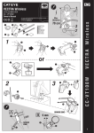
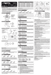
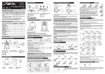
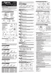
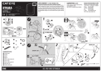
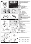
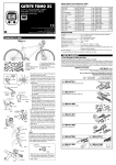
Precautions
CAT EYE Cordless 7
• Do not concentrate too much on the computer operations while riding.
• Be sure to securely mount the magnet, sensor and bracket on your bicycle,
and alweys check to insure they are mounted securely.
• Used batteries must be disposed of properly and in accordance with all
local regulations.
• Never disassemble the computer.
• For cleaning, use mild soap and a soft cloth. Wipe dry with a soft cloth. Paint
thinner, benzine, alcohol or other chemicals may damage the surface.
CYCLOCOMPUTER CC-FR7CL
E OWNER’S MANUAL
®
Cordless 7
U.S. Pat. Nos.4633216/4636769/4642606/5236759 Pat. and Design Pat. Pending
Copyright© 2002 CATEYE Co., Ltd.
CCMFR7CL-021210 Printed in Japan 066600165 1
IMPORTANT! PLEASE READ INSTRUCTIONS COMPLETELY
BEFORE ATTEMPTING TO INSTALL AND USE YOUR CAT EYE
CORDLESS 7 COMPUTER.
Installation of Computer:
1
3
Max.
Distance
70 cm
Magnet
1
2 Sensor
(Transmitter)
Bracket
This device complies with Part 15 of the FCC Rules. Operation is subject to the following two
conditions: (1) This device may not cause harmful interference, and (2) this device must accept any
interference received, including interference that may cause undesired operation.
Modifications
The FCC requires the user to be notified that any changes or modifications made to this device that are
not expressly approved by Cat Eye Co., Ltd. may void the user’s authority to operate the equipment.
About cordless system
The sensor picks up the wheel revolution signal and transmits the signal to the computer; the
computer calculates and displays the data on the screen.
CAUTION: In order to prevent external signal interference, the signal reception range is limited. For
best performance, the distance between the sensor and the computer must be kept within 70cm.
Attach the sensor at the upper part of your fork so that the distance becomes less than 70cm. The
signal reception range may shorten as a result of low temperature or lowered battery power.
In the following places and circumstances, interference may occur, resulting in malfunction:
• Near railroad crossing; in train cars.
• Near other cordless devices/television/personal computer/high power lighting system.
• Near the places where strong electromagnetic wave is generated; near television/ radio station; near
radar base.
• When being very close to another bicycle which also has a cordless cyclocomputer on its handlebar.
Computer Set-up (for first use, or after replacing battery)
1
3
2
5
Nylon Ties (S x 2)
4
Nylon Ties (L x 2)
Press All-Clear button (AC).
• Stored data is erased.
• Computer power is started.
• Total Odometer read's "zero".
• All digits shown then fades.
• Flashing "km/h" remains.
AC Button
SET button
Mounting View
1
Secure bracket to handlebar with nylon ties (fig. A).
Slide computer into mount until it snaps in place.
MODE button
1
2
Slide
Adjust between “mph” or “km/h” by pressing
the MODE button.
Click
5
(fig. A)
2
3
km/h
Use the below table
as the rough guide.
mph
MODE
Press the SET button to lock in your choice---OR--if you want to input previous mileage, hold the
MODE button (before pressing the SET button) for
2 seconds.
• Flashing Odometer digits will appear.
• MODE button increases the digit number.
• START/STOP button moves to the next digit.
• Press the SET button when complete.
3
(fig. B)
Spoke
Secure the sensor to fork leg as shown (fig. C).
NOTE: The distance between the computer and the sensor must not exceed 70 cm—if the sensor is too far
away from the computer head, the speed signal will not
register on the computer.
For best results, mount the sensor as high on the fork
leg as reasonably possible, so that the sensor is within
Front Fork
transmission range to the computer. However, the sensor must be close enough to spokes to allow proper disSensor Screw
4
tance to magnet (see below).
SET
MODE
increase
the figure
MODE
Front Fork
move to the next digit
2
(fig. C)
Less than 5mm
2
Magnet's
center
4
Marking line
3
3
Test by spinning the front wheel. Computer screen
should show speed. If not, make sure 1) the magnet is
close enough to sensor (within 5 mm); and 2) the sensor
is close enough to computer head (within 70 cm) and 3)
nothing is obstructing the line of sight between the sen-
ST./STOP
Sensor Base
NOTE: When the wheel rotates, the magnet MUST line up with the mark on the sensor.
ALSO NOTE: Magnet must pass within 5 mm of the sensor—if not, it will not trip the
sensor as it passes, and the computer will not register speed. Adjusting the sensor
position higher or lower on the fork leg or by rotating the sensor on the fork mount may
be required to achieve proper distance to the wheel magnet.
SET
3
•
•
•
•
•
•
Wheel circumference number is shown.
Look at chart to find TIRE SIZE in "mm".
To increase TIRE SIZE press MODE button.
To decrease press START/STOP button.
10-2999 mm can be registered.
Press SET button when finished.
increase
the figure
2
MODE
decrease
the figure
Spin
ST./STOP
OK
Sensor Pulse Indicator
!
Get your wheel
circumference
L mm
Lever
Mount the wheel magnet to a spoke on the front
wheel (fig.B), so the magnet faces the sensor.
Sensor Base
AC button
ST./STOP button
SET
Setup Completed (To Tm)
In this state Auto Time is ON.
L(mm)
Tire Size
12 x1.75
935
14 x 1.50
1020
14 x 1.75
1055
16 x 1.50
1185
16 x 1.75
1195
18 x 1.50
1340
18 x 1.75
1350
20 x 1.75
1515
20 x 1-3/8
1615
22 x 1-3/8
1770
22 x 1-1/2
1785
24 x 1
1753
24 x 3/4Tubular 1785
24 x 1-1/8
1795
24 x 1-1/4
1905
24 x 1.75
1890
24 x 2.00
1925
24 x 2.125
1965
26 x 7/8
1920
26 x 1(59)
1913
26 x 1(65)
1952
26 x 1.25
1953
26 x 1-1/8
1970
26 x 1-3/8
2068
26 x 1-1/2
2100
26 x 1.40
2005
26 x 1.50
2010
26 x 1.75
2023
26 x 1.95
2050
26 x 2.00
2055
26 x 2.10
2068
26 x 2.125
2070
26 x 2.35
2083
26 x 3.00
2170
27 x 1
2155
27 x 1-1/8
2161
27 x 1-1/4
2161
27 x 1-3/8
2169
650 x 35A
2090
650 x 38A
2125
650 x 38B
2105
700 x 18C
2070
700 x 19C
2080
700 x 20C
2086
700 x 23C
2096
700 x 25C
2105
700 x 28C
2136
700 x 30C
2170
700 x 32C
2155
700C Tubular
2130
700 x 35C
2168
700 x 38C
2180
700 x 40C
2200
The tire size is marked on
both sides of the tire.
Operation of Computer
Speed Scale Indicator - “mph” or “km/h” on main display flashes
when computer is measuring speed.
Display Features
Speed Scale Indicator
(When the unit doesn't receive signal for ten minutes,
it enters into power saving mode.)
0.0(4.0)-105.9 km/h
[0.0(3.0)-65.9 mph]
Display Modes - Press MODE button to shift lower display from
one mode to the next. The display modes change from Elapsed
Time (Tm), to Average Speed (Av), to Maximum Speed (Mx), to
Total Odometer (Odo), to Trip Distance (Dst).
2 weeks
later
Sensor Pulse Indicator
Flashes in synchronization with
signal from sensor.
Wheel Icon
Shows which
wheel is selected
CLOCK TIME - Hold MODE button for 2 seconds to display Clock
Time (this works in any of the display modes).
[To set correct Clock Time, press SET button when Clock Time is
showing in lower display. Use MODE button to increase the digit
number, and press SET to change to next digit. Press SET button
when complete].
AUTO TIME
- When this is activated, the computer will automatically start and stop measuring Elapsed Time (Tm), Average
Speed (Av), and Trip Distance (Dst), as soon as the bike starts
moving. AUTO TIME is activated when
icon shows in main
display.
To turn
feature on or off, press SET button while lower display
is in Elapsed Time (Tm), Average Speed (Av), or Trip Distance (Dst)
mode. For best results, operate the computer with
activated.
Power Saving Function
No signal
10 minuets
Speed (upper display)
Auto Time Icon
Starts/stops measuring
automatically.
Power Saving Mode
Sleep Mode
When wheel starts rotating,
it returns to normal mode.
To wake up the unit,
press MODE button or
ST./STOP button.
Pressing MODE and ST./STOP button simultaneously for a few
seconds in Mx mode, the computer will go to sleep mode.
How Mode Shifts in Lower Display
Tm
Dual Tire Size
You can set 2
different wheel
circumferences
Elapsed Time
0:00'00"-9:59'59"
How to Switch Wheel
Av
Average Speed
0.0-105.9 km/h
[0.0-65.9 mph]
Tm
Av
SET
Dst
Press SET button in
Tm, Av or Dst
SET
Hold down 2 seconds
If Elapsed Time exceeds 27 hours or Trip
Distance exceeds 999.99km, Average
Speed shows E. and ceases calculation.
In Odo
Mx
MANUAL MODE - Press the START/STOP button to start the
Elapsed Time (Tm), Average Speed (Av) and Trip Distance (Dst)
measurement, ONLY IF AUTO TIME
is not activated.
Road
Racer
Maximum Speed
MODE
MTB
ST./STOP
0.0(4.0)-105.9 km/h
[0.0(3.0)-65.9 mph]
MODE
Start/Stop
and
In any functions
other than Odo
Press simultaneously
2 seconds
How to Change Wheel Circumference
Reset Time, Distance, Average - To reset (zero out) ride data
(Elapsed Time, Trip Distance, Average Speed, and Max. Speed),
press MODE and START/STOP simultaneously. [Total Odometer is
not reset].
Odo
Total Distance
MODE
Default figure
Wheel A: 2096
Wheel B: 2050
Road
Racer
SET
0.0-99999 km [mile]
Increases
figure
MODE
ST./STOP
MODE
ST./STOP
Computer Features
Press simultaneously
Decreases
figure
Dst
Power Saving Function:
• Power saving mode ------- No signal for 10 minutes.
• Sleep mode ----------------- No signal for 2 weeks.
• Wake mode ----------------- Press MODE or START/STOP button.
Trip Distance
ST./STOP
MTB
0.00-999.99 km [mile]
From any mode
Dual tire size:
• Two different wheel size can be programed.
• Press MODE and START/STOP simultaneously for 2 seconds to switch size and .
• Wheel size
is designed for road bikes. Wheel size is designed for slower speeds
that can be typical for mountain bikes.
Hold
down
2 seconds MODE
How to Adjust Clock
If Km/h is selected for speed scale, it becomes 24-hour
clock. If mph is selected, it becomes 12-hour clock.
Returns to
above mode
MODE
Increases
figure
SET
SET
MODE
Clock
Decreases
figure
0:00-23:59
[1:00-12:59]
SET
ST./STOP
Troubleshooting
No display.
The battery in the computer run down?
Replace it with a new one and do all clear operation.
Incorrect data appears.
Do all clear operation. (Before this operation, write down your Odo data, and input it again after all
clear operation. In this way you can continue to accumulate your Odo.)
Cannot start measuring by START/STOP button.
icon on?
Is the
To operate manually, switch off the Auto Time.
Sensor pulse indicator does not flash. (Current speed does not appear.)
[If the sensor pulse indicator fails to flash, first spin front wheel to align computer with sensor. Indicator
will flash if computer is working. If not, this will pinpoint the problem to be: 1. dead battery; 2. distance
between sensor and unit is over 70cm.]
Is the clearance between the sensor and the magnet too large?
Are the magnet's center and the sensor's marking line aligned?
Re-adjust the positions of the magnet and the sensor.
Is the distance between the computer and the sensor too long?
Adjust the sensor's position so that the distance becomes less than 70cm.
The battery in the sensor run down?
Replace it with a new one. *In winter, battery's performance is degraded.
The battery in the computer run down?
Replace it with a new one and do all clear operation.
Maintenance
Computer
If the screen gets dim, please replace the battery. (Before replacing battery, write down your Odo data, and input it again after all clear operation.
This way you can retain your Odo data and continue to count, even after
replacing the battery.)
• Insert a new lithium battery (CR2032) with the (+) mark facing up.
• After replacing battery, do all clear operation and set up the unit again.
Sensor
If the sensor pulse symbol on the display gets dim, please replace the
battery. After replacing the battery, check the position of the sensor and
Limited Warranty
2-year warranty for computer/sensor only (excluding parts and batteries)
If trouble or damage occurs during normal use, the product will be repaired or replaced free of charge. Type your
name, address, date of purchase and the situation of trouble clearly on the warranty certificate, and send it back
to the appropriate service center together with the product. Insurance, handling and transportation charges shall
be borne by the customer. After being repaired or replaced, the product will be shipped back to the customer.
CO.,LTD. 2-8-25, Kuwazu, Higashi Sumiyoshi-ku, Osaka 546-0041 Japan
Attn.: CAT EYE Customer Service Section
Service & Research Address for United States Consumers:
CAT EYE Service & Research Center
1705 14th St. 115 Boulder, CO 80302
Phone: 303-443-4595
Toll Free: 800-5CATEYE
Fax: 303-473-0006
e-mail: [email protected]
URL: http://www.cateye.com
The following parts are available.
Close
Open
#169-6693
Parts Kit
Standard Parts
Replacing Battery
Battery ------------------------------ Computer:
Lithium Battery CR2032 X 1
Sensor:
Lithium Battery CR2032 X 1
Battery Life ------------------------- Computer:
approx. 1 year (in the case of being used for 1 hour every day)
Sensor:
until Total Distance reaches about 10,000km (6,250mile)
*This is the average figure of being used under 20°C temperature and the dis
tance between the computer and the sensor is 65cm.
Controller -------------------------- 4-bit 1-chip microcomputer (crystal controlled oscillator)
Display ----------------------------- Liquid crystal display
Sensor ------------------------------ No contact magnetic sensor
Wheel Circumference Range ---- 10mm-2999mm (default figure: A: 2095mm, B: 2050mm)
Working Temperature ------------ 0°C - 40°C (32°F - 104°F)
Dimension/Weight ---------------- 1-19/32 x 2-7/32 x 27/32" (40 x 56.5 x 21mm) / 1.06oz (30g)
* The factory-loaded battery life might be shorter than the above-mentioned specification.
* The specifications and design are subject to change without notice.
#169-6773
Attachment Kit
#169-6673
Sensor
#169-9691
Magnet
#169-6663
Bracket Kit
#166-5150
Lithium Battery (CR2032)
Close
Open
Optional Parts
• To clean the computer or accessories, use diluted neutral detergent on
a soft cloth, and then wipe it off with a dry cloth.
• If the gaps between the buttons and the unit get clogged with mud or
sand, wash with water.
Specification
#169-6667
Center
Mount Kit
#169-6669
Stem Mount Kit
#169-9760
Magnet for Composite
Wheel
#169-9690
Hi-Power Wheel
Magnet