1
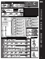
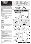
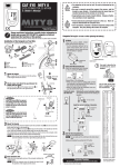
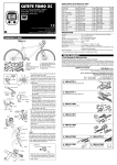
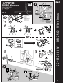
ENG
CYCLOCOMPUTER
CC - MC100W
Owner’s Manual
Max.
Distance
U.S. Pat. Nos. 4633216/4636769/4642606/5236759 and Design Pat. Pending
Copyright© 2004 CAT EYE Co., Ltd.
2
70 cm
5
6
7
4
3
8
1
3
2
Component name
1 Bracket
2 Speed Sensor A
3 Magnet
4 Bracket Rubber Pad
5 Sensor Rubber Pad
6 Nylon Ties (L x2)
7 Nylon Ties (S x2)
8 Double-sided tape
1
8
8
1
7
or
1
1
7
4
2
3
5
2
3
6
A
2
CC-MC100W
1
2
MICRO Wireless
MICRO Wireless
CCMC1W-041129 066600370
1
®
SENSOR ZONE
B
2
SENSOR
ZONE
3
5 mm
3
2
1
SETTING
PUSH!
SET : km/h
0
Tm 2
Dst 2
Av 2
AC
SET
9 3
1952
1953
1970
2068
2100
SET :
L = 2068 (mm)
(0100 - 3999 mm)
SETTING
END
START 2096
MODE
START/STOP
2097
2098
MENU
2068
Tire size
6 (59)
26 x 1(65)
26 x 1.25
26 x 1-1/8
37-590 26 x 1-3/8
26 x 1-1/2
MODE
AC
J
MODE
MENU
35
MODE
G
START/STOP
ETRTO
L mm
F
H
Tire size
L (mm)
12 x 1.75
14 x 1.50
14 x 1.75
16 x 1.50
47-305 16 x 1.75
18 x 1.50
18 x 1.75
47-406 20 x 1.75
20 x 1-3/8
22 x 1-3/8
22 x 1-1/2
24 x 1
24 x 3/4 Tubular
24 x 1-1/8
24 x 1-1/4
47-507 24 x 1.75
24 x 2.00
24 x 2.125
935
1020
1055
1185
1195
1340
1350
1515
1615
1770
1785
1753
1785
1795
1905
1890
1925
1965
ETRTO
23-571
37-590
40-559
47-559
50-559
54-559
57-559
57-559
Tire size
L (mm)
ETRTO
Tire size
26 x 7/8
26 x 1(59)
26 x 1(65)
26 x 1.25
26 x 1-1/8
26 x 1-3/8
26 x 1-1/2
26 x 1.40
26 x 1.50
26 x 1.75
26 x 1.95
26 x 2.00
26 x 2.10
26 x 2.125
26 x 2.35
26 x 3.00
27 x 1
27 x 1-1/8
1920
1913
1952
1953
1970
2068
2100
2005
2010
2023
2050
2055
2068
2070
2083
2170
2145
2155
32-630
27 x 1-1/4
27 x 1-3/8
650 x 35A
650 x 38A
650 x 38B
700 x 18C
700 x 19C
700 x 20C
700 x 23C
700 x 25C
700 x 28C
700 x 30C
700 x 32C
700C Tubular
700 x 35C
700 x 38C
700 x 40C
18-622
20-622
23-622
25-622
28-622
32-622
37-622
40-522
L (mm)
2161
2169
2090
2125
2105
2070
2080
2086
2096
2105
2136
2170
2155
2130
2168
2180
2200
b
OPERATION FLOW
Main
Sub
2
Tm
Tm 2
2 sec
0:00'00" - 9:59'59"
0:00'00" - 9:59'59"
MODE
MODE
MODE
Current Speeed
Dst
Dst 2
0.00 - 999.99 km [mile]
0.0 (4.0) - 105.9 km/h
[0.0 (3.0) - 65.9 mph]
0.00 - 999.99 km [mile]
MODE
MODE
MODE
0.0 (3.0) - 105.9 km/h
[0.0 (2.3) - 65.9 mph]
Av
Av 2
0.0 - 105.9 km/h
[0.0 - 65.9 mph]
0.0 - 105.9 km/h
[0.0 - 65.9 mph]
MODE
MODE
DATA RESET
Mx
0.0(4.0) - 105.9 km/h
[0.0(3.0) - 65.9 mph]
Main
Tm
Dst
Av
Mx
MODE
MODE
Odo
MENU
0.0 - 9999.9
10000 - 99999 km [mile]
MENU
START/STOP
Sub
MODE
2
0:00 - 23:59
[1:00 - 12:59]
Tm 2
Dst 2
Av 2
MODE
START/STOP
MENU FLOW
0
0
MENU SETTING
END
or
CO
Setting
(0100 - 3999 mm)
IN
Close
SET
d
COMPUTER
MENU
START/STOP
c
e
BATTERY
START
START/STOP
J
Open
(0 - 9)
CR2032
MENU
MODE
START/STOP
MODE
MODE
MODE
START/STOP
SET
ON / OFF
MENU
MODE
Setting
SET
START/STOP
START/STOP
24 hr / 12 hr
All Clear
00 - 59
0 - 24 / 1 - 12
MODE
START/STOP
START/STOP
SET
START/STOP
SENSOR
00000 - 99999 km [mile]
MENU
MODE
MODE
START/STOP
START/STOP
START/STOP
a
MENU
MODE
Input
ENG
MODE
Tire size
26 x 1 - 3/8
C
MENU
I
START km/h
3. Wheel Circumference
TIRE
E
MICRO Wireless
Tm
Dst
Av
Mx
Odo
2. Select km/h or mph
D
B
CC-MC100W
a
1. All Clear
A
MODE
SET
Close
CO
IN
Open
or
CR2032
!
c
MENU
&
d
START/STOP
START/STOP
SET
2
The sensor was designed to receive signals within a limited range to
prevent sensor signal interference. Thus, the sensor and computer
must be relatively close. If the temperature or battery power is low,
they may need to be even closer than normal. The sensor must be
installed at the top of the fork, and the distance between the sensor
and the computer should not exceed approximately 70 cm. Install
the computer on the stem, with its bottom surface facing the sensor.
(Take into account the angle of the stem.)
Interference may occur, resulting in malfunction, if the computer is:
• Near a TV, PC, radio, motor, or in a car or train.
• Close to a railroad crossing, railway tracks, TV stations and or
radar base.
• Close to a second bicycle with wireless sensors.
Correct installation of sensor and magnet
A Attach the magnet 3 so that it passes through the sensor
zone of the sensor 2.
B Be sure to have a 5 mm-or-less clearance between the sensor
2 and magnet 3.
Part names
A Current Speed
B Sensor signal reception icon
Flashes in sync with sensor signals.
C Sub measurement icon
D Pace arrow
Indicates whether the current speed is faster or slower than
the average speed. ( Faster Slower)
EF Auto mode icon
Speed unit
G Mode symbol ....................................................................
b
Indicates the mode currently selected.
Tm (Tm 2) ............... [Elapsed Time]
Dst (Dst 2) ............... [Trip Distance]
Av (Av 2) .................. [Average Speed]
Mx ............................ [Maximum Speed]
Odo .......................... [Total Distance]
............................ [Clock]
H Wheel size icon
I Backlight button
J Battery Case Cover
Starting/Stopping measurement
This computer allows automatic (Auto-mode) or manual measurement.
During measurement, the speed unit icon flashes. The maximum
speed and total distance will update, regardless of measurement.
• Auto-mode (automatic measurement)
If the
icon is visible, measurement is automatic.
In Auto-mode, starting/stopping measurement using the START/
STOP button is impossible.
• Manual measurement
If the
icon does not light, starting/stopping the measurement using the START/STOP button is possible.
* Use the menu screen to toggle between Auto-mode ON and
OFF. For further information, see the MENU FLOW.
Switching Mode symbol .................................... b
Press the MODE button to switch measurement according to the
OPERATION FLOW.
Press the MODE button for 2 seconds to switch from Main to Sub
measurement.
• Sub measurement
When Main measurement starts/stops, Sub measurement starts/
stops accordingly. Note, however, that the main and sub measurements must be reset individually.
Resetting Main and Sub measurement at different times allows
interval measurement to be carried out.
* In the sub measurement the pace arrow compares the current
speed to average speed 2.
Resetting data ........................... Main : c Sub : d
To reset measurement data, display the Main/Sub measurement
data and press the START/STOP and MODE buttons simultaneously. Trip distance is not reset.
Backlight
Press the backlight button to illuminate the display for 3 seconds.
If the battery is low, the wheel size icon flashes and the display
does not illuminate.
Power-saving function
If the computer has not received a signal for 10 minutes, powersaving mode will activate and only the clock will be displayed. When
the computer receives a sensor signal again, the measuring screen
reappears. If two weeks’ inactivity elapses, power-saving mode will
change to SLEEP mode. Pressing the MODE or START/STOP button in SLEEP mode brings up the measuring screen.
Dual Wheel Size
Two wheel sizes (Wheel sizes
and
) can be registered on
the computer. This is useful when the computer is shared between two bicycles or when one bicycle uses different wheel sizes
at different times. Wheel size B has pre-programmed for a 26x1.95"
size tire.
* Use the menu screen to toggle between
and
. For further information, see the MENU FLOW.
Changing the computer settings
Replacing the Battery
• Computer
If the Wheel Size icon (
or
) flashes, replace the battery.
The Total Distance can be entered manually. Before removing
the battery, note the current Total Distance. Install a new lithium
battery (CR2032) with the (+) side facing upward.
Then re-start the computer according to the SETTING procedure, and then set the clock from the MENU FLOW.
• Sensor
If sensor reception is poor, replace the battery. Then check the
positions of the battery and magnet.
Specification
Battery ............. Computer: Lithium Battery CR2032 X 1
Sensor: Lithium Battery CR2032 X 1
Battery Life ...... Computer: approx. 1 year (If the computer is used for
1 hour/day without the backlight on)
Sensor: until Total Distance reaches about 10,000 km
(6,250 mile)
*This is the average figure of being used under 20°C temperature and
the dis tance between the computer and the sensor is 65 cm.
* If the backlight is used frequently, the battery life diminishes accordingly.
Controller .......................... 4-bit 1-chip microcomputer
(crystal controlled oscillator)
Display ............................... Liquid crystal display
Sensor ............................... No contact magnetic sensor
Wheel Circumference Range ....... 0100 mm - 3999 mm
(default figure A : 2095 mm, B : 2050 mm)
Working Temperature ....... 0°C - 40°C (32°F - 104°F)
Dimension/Weight
52.5 x 38 x 22 mm [2-3/32" x 1-1/2" x 7/8"]
/ 30 g [1.06 oz]
* The factory-loaded battery life might be shorter than the above-mentioned specification.
* The specifications and design are subject to change without notice.
Standard Parts
ENG
#169-6590
Parts Kit
#169-6580
Speed Sensor A
MICRO Wireless
Wireless Sensor
No display.
Is battery in the computer run down?
Replace it, and re-enter the correct information. (All Clear a ).
Incorrect data appears.
Do all clear operation. (All Clear a ).
Pressing the START/STOP button does not calculate Elapsed Time.
icon illuminated?
Is the
To start/stop measurement using the START/STOP button, turn off
Auto-mode.
The sensor signal icon does not flash. (The speed is not displayed.)
[If the signal icon does not flash, reduce the distance between the sensor
and computer, adjust the position of the magnet, and spin the wheel again.
If the icon now flashes, this indicates that the computer and sensor are
too far apart or that the battery is low.]
Is the clearance between the sensor and magnet too great?
Does the magnet pass through the sensor zone?
Adjust the positions of the magnet and sensor.
Is the computer installed at the correct angle?
Install the computer with its bottom surface facing the sensor.
Is the distance between the computer and sensor too great?
Install the sensor closer to the computer.
Is the sensor battery weak?
In winter, battery performance degrades.
Replace it.
Is the computer’s battery weak?
Replace it with a new one. (All Clear a ).
#169-6570
Bracket kit
#169-9691
Wheel Magnet
#166-5150
Lithium Battery (CR2032)
Option Parts
#169-6667
Center Mount Kit
#169-9760
Magnet for Composite Wheel
#169-9690
Hi-Power Wheel Magnet
This device complies with Part 15 of the FCC Rules. Operation is subject to the following two
conditions: (1) This device may not cause harmful interference, and (2) this device must
accept any interference received, including interference that may cause undesired operation.
Modifications The FCC requires the user to be notified that any changes or modifications
made to this device that are not expressly approved by CatEye Co., Ltd. May void the user’s
authority to operate the equipment.
LIMITED WARRANTY - 2-Year Computer/Sensor only
(Accessories/Attachments and Battery Consumption excluded)
If trouble occurs during normal use, the part of the Main Unit or sensor will be repaired or
replaced free of charge. The service must be performed by CatEye Co., Ltd. To return the product, pack it carefully and remember to enclose the warranty certificate with instruction for repair.
Please write or type your name and address clearly on the warranty certificate. Insurance, handling and transportation charges to our service shall be borne by person desiring service.
CO.,LTD.
2-8-25, Kuwazu, Higashi Sumiyoshiku, Osaka 546-0041 Japan
Attn: CATEYE Customer Service Section
Service & Research Address for USA
CATEYE Service and Research Center
1705 14th St. 115 Boulder, CO 80302
Phone: 303.443.4595
Toll Free: 800.5CATEYE
Fax: 303.473.0006
E-mail: [email protected]
URL: http://www.cateye.com
CC-MC100W
Troubleshooting
CAUTION
• Do not concentrate on the computer while riding. Be sure to
ride safely!
• Install the magnet, sensor, and bracket securely. Check these
periodically.
• Dispose of used batteries according to local regulations. If swallowed, consult a doctor immediately.
• Avoid having the computer in hot direct sunlight for extended
periods.
• Do not disassemble the computer.
• Clean the computer and accessories with a soft cloth dampened with a neutral detergent. Do not use thinners, benzene, or
alcohol on the computer.
If the MENU button is pressed with the measuring screen displayed, the menu screen appears. Press the START/STOP button
when measurement has stopped and no signal is being received
to change menu settings.
• Setting the clock
Set the clock via
Settings in the MENU FLOW.
* For the Speed unit, reset Main and Sub measurement data
before changing settings.
* For further information, see the MENU FLOW.
Maintenance
To clean the computer or accessories, use diluted neutral detergent on a soft cloth, and then wipe it off with a dry cloth.
3