1
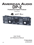
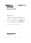
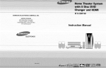
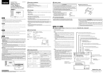
deutsch de Installation and Operation Guide Crystalline Solar Modules Bosch Solar Module c-Si M 60 IN30125 en Operating instructions Issue 01/2013 Bosch Solar Module c-Si M 48 I Bosch Solar Module c-Si M60 I Bosch Solar Module c-Si M60 S I Bosch Solar Module c-Si P60 Robert Bosch GmbH 2 | Table of Contents I Introduction en Table of Contents en Disclaimer of liability I General information | 3 2 Disclaimer of liability the Module Data Sheet provided with this product. Determine local permits, installation and inspection requirements before installing module(s). If not otherwise Introduction2 2 Disclaimer of liability 3 General information3 General safety 5 Installation5 6 Specifications9 7 Wiring9 8 Grounding10 9 Diodes11 10 Maintenance11 11 Disposal11 specified, it is recommended that the requirements of nance Manual and the conditions of installation, opera- the U.S. National Electric Code (NEC) be followed. tion, use and maintenance of the module are beyond 3 4 Since the use of this Installation, Operation and Mainte- 4 Bosch Solar Energy AG control, Bosch Solar Energy AG This photovoltaic module produces electricity when does not assume responsibility and expressly disclaims exposed to the sunlight, even at low light levels or when liability for loss, damage, injury or expense arising out of other sources illuminate the front face. The electrical or in anyway connected with such installation, operation, hazard from the voltage and current of a single module is use or maintenance of the module. low. However, the voltage increases as modules are connected in series and the available current increases Bosch Solar Energy AG assumes no responsibility for any as the modules are connected in parallel. Thus, for a infringement of patents or other rights of third parties module connected within a system, contact with electri- that may result from use of the module. No license is cally active parts of the module such as terminals can granted by implication or otherwise under any patent or result in lethal shock, sparks, and burns. The only way to patent rights. eliminate this hazard is to prevent exposure of the module(s) to light. The information in this Manual is based on Bosch Solar Energy AG knowledge and experience and is believed to be reliable; but such information including product specImportant Notice! ifications (without limitations) and suggestions do not constitute a warranty, expressed or implied. Bosch Solar Energy AG reserves the right to make changes to the product, specifications or this manual without prior notice. To avoid the hazard of electric shock and injury when 3 General information 1 Introduction installing, wiring, operating and maintaining the PV modules Cover the entire front surface of the PV modules with The installation of solar PV modules requires a great a dense, opaque material such as the cardboard box, degree of skill and DC voltage exceeds 100 V, it only be during installation and handling of the modules. This manual contains information regarding installation, performed by a qualified licensed professional, including, Do not expose Back sheet foil directly to sunlight operation, maintenance and safety handling of Bosch without limitation, licensed contractors and licensed Work only under dry conditions, with dry modules Solar Energy AG photovoltaic modules. Before installation electricians. The installer assumes the risk of all injury or using the PV modules, it is important to read this man- that might occur during installation, including without Be sure to completely ground all modules. ual and understand the instructions carefully. limitation, the risk of electric shock. Since sparks may occur, do not install the module and tools. where flammable gases or vapors are present. Module installation and operation should be performed by qualified personnel only. Important Notice! Children and unauthorized persons should not be allowed near the installation of PV modules. Use module for its intended function only. Be sure that all other system components are compatible, and they do not subject the module to mechaniFor your safety and the safety of others, please read the entire Installation, Operation and Maintenance Manual carefully prior to installing, wiring, operating and per- cal or electrical hazards. Do not touch terminals while module is exposed to light or during installation. forming maintenance of PV modules. Also, carefully read Bosch Solar Module c-Si M 60 IN30125 Bosch Solar Energy AG Bosch Solar Module c-Si M 60 IN30125 Bosch Solar Energy AG english 1 Provide suitable guards to prevent contact with 30 VDC or greater. As a Precaution use properly insu- en 4 Genaral safety 4. Under normal conditions, a photovoltaic module is module. Do not use the junction box to hold or transport the module. Do not drop module or allow objects to fall on module. Do not stand or step on the module. Do not disassemble, modify or adapt the module or remove any part or labeling installed by the manufacturer. Do not drill holes in the frame or glass of the module. Do not treat back sheet and front surface of the module with paint and adhesives. sonally, yearly). The location should be selected to likely to experience conditions that produce more have direct access to sunlight from 9:00a.m. to current and/or voltage than reported at Standard 3.00p.m. on the shortest day of the year. Calculate Follow all permission, installation and inspection re- Test Conditions. Accordingly, the values of Isc and the tilt angle by using the site latitude plus 20 de- quirements. Voc marked on this module should be multiplied by a grees, with modules facing south in the northern Before installing modules, contact the appropriate factor of 1.25 when determining component voltage latitudes and north in the southern latitudes. This authorities to determine permissions, installation, ratings, conductor capacities, fuse sizes, and size of will result in consistent energy output throughout the and inspection requirements which should be fol- controls connected to the PV output. year. lated tools only. Do not damage or scratch the back sheet of the General safety I Installation | 5 en lowed. 5. Refer to section 690-8 of the National Electric Code Electrically ground modules for all systems of any voltage. The appropriate material should be used for mount- (NEC) for an additional multiplying factor of 125 % ing hardware to prevent the module frame, mounting (80 % de-rating) which may be applicable. If not otherwise specified, it is recommended that 6. Conductor recommendations: single conductor cable, requirements of the latest National Electrical Code type USE-2 12 AWG, rated 600 V/1000 V minimum, (USA) or other national or international electrical 90° C minimum, marked sunlight resistant. structure, and hardware itself from corrosion. Install modules where they are not shaded by obstacles like buildings and trees. standards be used. Especially pay attention to avoid partially shading the modules by objects during the daytime. Be sure that the construction or structure (roof, facade, etc.) where the modules are being installed 5 Installation For roof mounted systems, provide adequate rear ventilation under a module for cooling (100 mm: 4in Do not artificially concentrate light on the module. has enough strength. For modules mounted on roofs, Do not wear metallic jewelry while installing or special construction or structures may be required to Clearance of 7mm: 0.25” or more between modules help provide proper installation. Both roof construc- is required to allow for thermal expansion of the trouble shooting the module. Do not change the wiring of bypass diodes. tion and module installation design have an effect on Do not disconnect modules under load the fire resistance of a building. Improper installation gap minimum) Important Notice! frames. Observe the specifications for mounting areas ac- may contribute to fire hazards. Additional devices cording to Illustrations 1 and 2. To help avoid breakage problems such as ground fault, fuses, and disconnects may be Attachment with clamps on the narrow sides of the Always transport and store the module in the ship- required. ping container provided. When carrying a module two or more people should carry it by its frame and wear non-slip gloves (to avoid injury by a slipping module, to a foot, or cuts by Do not use modules of different specifications in the Follow all safety precautions of other system components used. the edge of a frame, and so on). Do not leave the module unsupported or unsecured The attachment of the solar module can be per- To satisfy regulatory requirements, when installing the formed with clamps (or as an alternative, directly on or use of the modules. This section contains electri- the installation holes). When clamping systems are cal and mechanical specifications needed before used, the clamp surface per attachment point on the using your Bosch Solar Energy AG PV modules. module must amount to at least 400 mm². Modules should be firmly fixed in place in a manner prior to installation. For example, wind can cause a modules, be sure to: suitable to withstand all expected loads, including module which is leaning against a fence to fall and 1. Use only stranded or solid copper single-conductor wind and snow loads. Module mounting holes are Position of the installation drill holes in accordance with Illustrations 3 break. Avoid application of excessive bending or type UF cable or USE cable rated sunlight resistant, provided for easy installation and proper mechanical Please contact your Bosch Solar Energy AG authorized twisting forces to the module. for modules and modules interconnect wiring that is loading. representative with questions regarding A module with broken glass or torn back-skin cannot be repaired and must not be used since contact with any module surface or the frame can produce electrical shock. Broken or damaged modules must be handled care General Please read this guide completely before installation same system. solar module may not be performed. Modules should be mounted with the orientation and exposed to weather. 2. Observe the requirements described in sections mounting profiles for modules. tilt angle required for consistent performance (sea- labeled INSTALLATION and SPECIFICATIONS of this manual. 3. Grounding of the module frame is required. When fully and disposed of properly. ground wires greater than 6 mm2 (No.10 AWG) are Broken glass can be sharp and can cause injury if not required, the installer will need to provide suitable handled with the appropriate protective equipment. terminal connectors. Bosch Solar Module c-Si M 60 IN30125 Bosch Solar Energy AG Bosch Solar Module c-Si M 60 IN30125 Bosch Solar Energy AG english 4 | General information I General safety 6 | Installation en en Installation | 7 1660 ± 2 l/4 english 1000 375 8x Module mounting holes 830 l/2 l/7 l mounting holes l/7 267,5 l/4 990 ± 2 2x Mounting holes for grounding cable Ø5 18,5 size: 8 x 12 mm Figure 1: Mounting area, vertical 18 l/7 l/7 l mounting holes Figure 3: reverse side Bosch Solar Module c-Si M 60 IN30125 l/4 l/2 l/4 Figure 2: Mounting area, horizontal Bosch Solar Module c-Si M 60 IN30125 Bosch Solar Energy AG Bosch Solar Module c-Si M 60 IN30125 Bosch Solar Energy AG 8 | Grounding | Maintenance and upkeep | Disposal Clearance between the module frame and the mounting surface is required to allow cooling air to circu- The installation place should be less than 1,000 m (3,280ft) above sea level. only if the wind pressure load for a module is less any condensation or moisture to dissipate. The mod- than 2,400N/m2 (50PSF). Peak / Rated Power (Pmax, Wp) 225 The salt damage is heavy at the installation place. Max Power Voltage (Vmp, V) 29.40 General The hail and snow damage is heavy at the installation Max Power Current (Imp, A) 7.80 All wiring should be done in accordance with applicable Open Circuit Voltage (Voc, V) 36.90 Short Circuit Current (Isc, A) 8.30 Power Tolerance (%) ±3 Factory Installed Bypass Diode (Qty) 3 Bypass Diode Rating (A) 15 Max. Series Fuse Rating (Amps) 15 Maximum System Voltage (VDC) 1000 Fire Resistance Rating Class C Temp. coefficient of Voc (%/ºC) -0.32 Temp. coefficient of Isc (%/ºC) 0.032 imum system voltage / Open circuit voltage of the Temp. coefficient of Pmax (%/ºC) -0.46 module) – 1) at standard condition, AM1.5G, 25 Cable (1Mtr Length-2Nos) 4Sq.mm, 12AWG Length, mm (Inches) 1660(65.35) Width, mm (Inches) 990(43.92) Frame Depth(Thk), mm (Inches) 42 (1.65) Weight, Kg (Pounds) 20(44.09) Mounting Hole, mm (inches) 8x12 (0.315x0.472), Qty- 8 Ground Hole dia., mm (Inches) Ground back – 5mm (0.196) dia., Qty-2 the module. The ambient temperature of the installation place For roof application, the modules should be mounted over a fire resistant covering rated for the application exceeds SOC. place. The sand and dust damage is heavy at the installation place. The air pollution, chemically active vapors, acid rain, Standard Operating Condition and/or soot, etc. are heavy at the installation place Bosch Solar Energy AG recommends that modules be operated under Standard Operating Conditions (SOC). 3. Application Class & Safety Class An installation location with conditions exceeding SOC The modules are qualified for application class A: Haz- or with other Special Conditions (see below) should be ardous voltage (IEC 61730:Higher than 50VDC; EN avoided. SOC of Bosch Solar Energy AG modules is as 61730: Higher than 120 V), hazardous power applica- follows: tions (Higher than 240 W) where general contact access 1. Standard Operating Conditions (SOC) is anticipated (modules qualified for safety through EN The modules should be operated only in terrestrial 61730-1 and 61730-2 within this application class are applications. No space or other Special Conditions 60 Cell Module Series IN30125 – 225 2. Special Conditions quirements for building or structural fire safety. 7 Wiring Model Number with sealant that prevents air from circulating under Refer to your local authority for guidelines and re- 6 Specification Important Notice! ule should never be sealed to the mounting surface module frame. Specification I Wiring | 9 Installations more than 1,000 m (3,280 ft) are allowed late around the back of the module. This also allows Leave 4 inches of clearance between the roof and the en considered to meet the requirement for Safety Class II). (see below). The measured ambient temperature of the installation location should be within –20º C (-4° F) to 40º C (104° F). The lower and upper temperature limit is defined as the monthly average low or high of the installation location. The relative humidity should be within 45 % to 95 %. electrical codes. All wiring should be done by a qualified, licensed professional. Wiring should be protected to help ensure personal safety and to prevent its damage. All Bosch Solar Energy AG modules are equipped with wires and quick connectors. Modules have been designed to be easily interconnected in series. Modules can be wired in series to increase voltage. Connect wires from positive terminal of one module to the negative terminal of the next module. All modules connected in series should be of the same model number and/or type. Make sure the number of modules connected in series does not exceed: ((Max- degrees temperature, 1,000 W/m2. Connect modules in parallel to increase current. Connect wires from the positive terminal of the one module to the positive terminal of the next module. Do not connect modules in parallel without using a connection box. The number of parallel strings depends on the system integrator’s requirements and the inverter ratings. These modules contain factory installed bypass diodes. If these modules are incorrectly connected to each other, the bypass diodes, cables, or junction box may be damaged. Note: Modules in parallel can be done as applicable Notes: Module Version Positive Pole Negative Pole 1. Rated electrical characteristics are within 10 % of IN xx125 Tyco, Neutral 6-1394461-2 Tyco, Minus 0-1394462-4 the values measured at Standard Test Conditions (STC) of: 1000W/m2, 25ºC cell temperature and solar special irradiance per IEC 60904-3. Coding for connector plug1 1IN Bosch Solar Module c-Si M 60 IN30125 Bosch Solar Energy AG xxxxx: Internal technology code Bosch Solar Module c-Si M 60 IN30125 Bosch Solar Energy AG english Notes on Installation en 10 | Wiring | Grounding several modules on a support structure with associ- 8 Grounding en Diodes | Maintenance | 11 9 Diodes away by periodic rainfall, but in some instances some maintenance is recommended to clean the surface of the glass with water and a soft cloth or sponge. A ated wiring. Use copper wire that is sunlight resistant and is insulated to withstand the maximum possible system open circuit voltage. Check your local codes Important Notice! Bypass Diodes mild non-abrasive detergent may be applied for per- When the modules are shaded partially, it may cause sistent dirt. reverse voltage across cells or modules, because the for requirements. Use system wiring with suitable cross-sectional areas and connectors that are approved for use at the However it is advisable to perform periodic inspec- current from other cells in the same series is forced to tion of the modules for damage to glass, back-skin, flow through the shaded area. This may cause undesir- frame, junction box or external electrical / loose able heating to occur. When a bypass diode is wired in connections and corrosion by the authorized profes- Bonding connection parallel with the series string, the forced current will sional. must not be greater than the specified maximum Module frames should be connected to an earth ground flow through the diode and bypass the shaded module, system voltage for the module. for safety and protection from lightning. A good connec- thereby minimizing module heating and array current should ever be used on the coated front glass. No tion between the grounding hardware is essential for an losses. alkali based chemicals should be used, including maximum short-circuit current of the module. The maximum open circuit voltage of the system When reverse currents can exceed the value of the ammonia based solutions. maximum protective fuse marked on the back of the effective ground. The anodization on a module frame module, a properly rated and certified over current provides a coating to minimize the corrosion due to The use of a diode to bypass the shaded area can mini- device (fuse or circuit breaker) must be connected in weather and it acts as a barrier that reduces the effec- mize both heating and array current reduction. series with each module or string of modules. tiveness of the grounding connection. For an adequate The fuse used is a glass / HRC type of rating 15 Amps. The fuse rating has to begreater than or equal Always wear rubber gloves for electrical insulation while maintaining, washing or cleaning modules. Once a year, check that growing foliage has not ground, the grounding hardware should pierce the ano- All Bosch Solar Energy AG modules are equipped with dization layer. factory installed bypass diodes. The factory installed diodes provide proper circuit protection for the systems to 135 % of the module’s short circuit current. No aggressive and abrasive cleansers or chemicals caused module shading. Correct if this condition has occurred. As required, check that the system voltage and cur- within the specified system voltage, so that you do not rent output (or power output) is consistent with the the value of the maximum protective fuse marked on need any other additional bypass diodes. If your system expected output. Such a check will help to determine the back of the module. specifications require you to add or change diodes, if array cleaning is needed, if there are loose or cor- please contact authorized Bosch Solar Energy AG repre- roded connections, or if there is a component prob- sentative for recommendations for the proper diode type. lem. The rating of the over-current device shall not exceed Match the polarities of cables and terminals when making the connections; failure todo so may result in damage to the module. Connecting modules in reverse polarity to a high current source, such as a battery, will destroy the bypass diodes and render the module inoperative. Grounding Screw Place cup washer between frame and wire with concaveside up Flat washer Ground Wire Cup washer Bypass diodes are not user replaceable. Warning: Do not attempt to clean a module with a Blocking Diodes broken glass over or a perforated backsheet. Such a Blocking diodes are typically placed between the battery module can present a serious shock hazard. and the PV module output to prevent battery discharge at night. Bosch Solar Energy AG modules do not contain a blocking diode when shipped from the factory. It is The junction box is under no circumstances being opened. Opening the junction box may void the Star washer warranty. Nut Modules with a suspected electrical problem should be returned to Bosch Solar Energy AG for inspection recommended that a charge controller be used to pre- 11 Disposal vent the batteries from being overcharged and discharged at night. Important Notice! Frame and possible repair or replacement as per the warranty conditions provided by Bosch Solar Energy AG. Side View 10 Maintenance The above figure is for hardware mounting reference. Defective or old solar modules must be appropriately Important Notice! disposed of. These may not be disposed of in household waste. It is common for dust and dirt particles to accumulate on the surface of the module. This can reduce the optimal output performance of the solar modules. Normally, the accumulated dust will be washed Bosch Solar Module c-Si M 60 IN30125 Bosch Solar Energy AG Bosch Solar Module c-Si M 60 IN30125 Bosch Solar Energy AG english The term “array” is used to describe the assembly of en de Bosch Limited Hosur Road, Adugodi Bangalore 560 030 Indien Tel.: + 91 80 6657 1600 Mobil: + 91 97 4149 6854 www.bosch-solarenergy.com Bosch Solar Module c-Si M 48 I Bosch Solar Module c-Si M60 I Bosch Solar Module c-Si M60 S I Bosch Solar Module c-Si P60 Robert Bosch GmbH