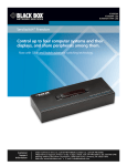
1
® ® NETWORK SERVICES KV9804A ServSwitch™ Wizard DP USB Share a high resolution DisplayPort video display, stereo audio, USB keyboard, mouse and two other USB devices between up to four systems. You can switch peripherals in unison or mix them separately between the systems to suit your immediate needs. COMPUTER KVM SPK USB1 USB2 MODE S e r v S w i tc h ™ W i za rd B L A C K Customer Support Information B OX D ESKTO P DP USB KV M SW ITC H Order toll-free in the U.S.: Call 877-877-BBOX (outside U.S. call 724-746-5500) FREE technical support 24 hours a day, 7 days a week: Call 724-746-5500 or fax 724-746-0746 Mailing address: Black Box Corporation, 1000 Park Drive, Lawrence, PA 15055-1018 Web site: www.blackbox.com • E-mail: info@ blackbox.com ServSwitch™ Wizard DP USB Trademarks Used in this Manual Black Box and the Double Diamond logo are registered trademarks, and ServSwitch is a trademark, of BB Technologies, Inc. Mac is a registered trademark of Apple Computer, Inc. Linux is registered trademark of Linus Torvalds. Windows is a registered trademark of Microsoft Corporation. NetWare is a registered trademark of Novell, Inc. Sun is a trademark of Sun Microsystems, Inc. Unix is a registered trademark of UNIX System Laboratories, Inc. BSD is a registered trademark of UUNet Technologies, Inc. Any other trademarks mentioned in this manual are acknowledged to be the property of the trademark owners. We‘re here to help! If you have any questions about your application or our products, contact Black Box Tech Support at 724-746-5500 or go to blackbox.com and click on “Talk to Black Box.” You’ll be live with one of our technical experts in less than 30 seconds. Page 2 724-746-5500 | blackbox.com FCC and IC RFI Statements Federal Communications Commission and Industry Canada Radio Frequency Interference Statements This equipment generates, uses, and can radiate radio-frequency energy, and if not installed and used properly, that is, in strict accordance with the manufacturer’s instructions, may cause interference to radio communication. It has been tested and found to comply with the limits for a Class A computing device in accordance with the specifications in Subpart B of Part 15 of FCC rules, which are designed to provide reasonable protection against such interference when the equipment is operated in a commercial environment. Operation of this equipment in a residential area is likely to cause interference, in which case the user at his own expense will be required to take whatever measures may be necessary to correct the interference. Changes or modifications not expressly approved by the party responsible for compliance could void the user’s authority to operate the equipment. This digital apparatus does not exceed the Class A limits for radio noise emission from digital apparatus set out in the Radio Interference Regulation of Industry Canada. Le présent appareil numérique n’émet pas de bruits radioélectriques dépassant les limites applicables aux appareils numériques de la classe A prescrites dans le Règlement sur le brouillage radioélectrique publié par Industrie Canada. 724-746-5500 | blackbox.com Page 3 ServSwitch™ Wizard DP USB Instrucciones de Seguridad (Normas Oficiales Mexicanas Electrical Safety Statement) 1. T odas las instrucciones de seguridad y operación deberán ser leídas antes de que el aparato eléctrico sea operado. 2. Las instrucciones de seguridad y operación deberán ser guardadas para referencia futura. 3. Todas las advertencias en el aparato eléctrico y en sus instrucciones de operación deben ser respetadas. 4. Todas las instrucciones de operación y uso deben ser seguidas. 5. E l aparato eléctrico no deberá ser usado cerca del agua—por ejemplo, cerca de la tina de baño, lavabo, sótano mojado o cerca de una alberca, etc.. 6. El aparato eléctrico debe ser usado únicamente con carritos o pedestales que sean recomendados por el fabricante. 7. El aparato eléctrico debe ser montado a la pared o al techo sólo como sea recomendado por el fabricante. 8. Servicio—El usuario no debe intentar dar servicio al equipo eléctrico más allá a lo descrito en las instrucciones de operación. Todo otro servicio deberá ser referido a personal de servicio calificado. 9. El aparato eléctrico debe ser situado de tal manera que su posición no interfiera su uso. La colocación del aparato eléctrico sobre una cama, sofá, alfombra o superficie similar puede bloquea la ventilación, no se debe colocar en libreros o gabinetes que impidan el flujo de aire por los orificios de ventilación. 10. El equipo eléctrico deber ser situado fuera del alcance de fuentes de calor como radiadores, registros de calor, estufas u otros aparatos (incluyendo amplificadores) que producen calor. 11. E l aparato eléctrico deberá ser connectado a una fuente de poder sólo del tipo descrito en el instructivo de operación, o como se indique en el aparato. 12. Precaución debe ser tomada de tal manera que la tierra fisica y la polarización del equipo no sea eliminada. 13. Los cables de la fuente de poder deben ser guiados de tal manera que no sean pisados ni pellizcados por objetos colocados sobre o contra ellos, poniendo particular atención a los contactos y receptáculos donde salen del aparato. 14. El equipo eléctrico debe ser limpiado únicamente de acuerdo a las recomendaciones del fabricante. 15. E n caso de existir, una antena externa deberá ser localizada lejos de las lineas de energia. 16. El cable de corriente deberá ser desconectado del cuando el equipo no sea usado por un largo periodo de tiempo. 17. Cuidado debe ser tomado de tal manera que objectos liquidos no sean derramados sobre la cubierta u orificios de ventilación. 18. Servicio por personal calificado deberá ser provisto cuando: A: El cable de poder o el contacto ha sido dañado; u B: Objectos han caído o líquido ha sido derramado dentro del aparato; o C: El aparato ha sido expuesto a la lluvia; o D: El aparato parece no operar normalmente o muestra un cambio en su desempeño; o E: El aparato ha sido tirado o su cubierta ha sido dañada. Page 4 724-746-5500 | blackbox.com Table of Contents Contents 1. Specifications............................................................................................................................................................................... 6 1.1 What‘s Included................................................................................................................................................................. 6 1.2 Additional Items You May Need........................................................................................................................................ 6 2. Overview..................................................................................................................................................................................... 7 2.1 Wizard DP USB features..................................................................................................................................................... 8 3. Installation................................................................................................................................................................................... 9 3.1 Mounting the modules – desk or rack............................................................................................................................... 9 3.1.1 Rack mount........................................................................................................................................................... 9 3.2 Connections.................................................................................................................................................................... 10 3.2.1 User console........................................................................................................................................................ 10 3.2.2 Computer connections........................................................................................................................................12 3.2.3 Power connection................................................................................................................................................13 3.2.4 Optional remote control...................................................................................................................................... 14 3.3 Synchronizing multiple units.............................................................................................................................................15 3.4 Channel switching by external control............................................................................................................................. 16 3.4.1 OPTIONS port pinout.......................................................................................................................................... 16 3.4.2 Control by RS-232 serial.......................................................................................................................................17 4. Configuration............................................................................................................................................................................ 18 4.1 Using the configuration menu......................................................................................................................................... 18 4.2 General configuration...................................................................................................................................................... 19 4.2.1 Changing hotkeys............................................................................................................................................... 19 4.2.2 Mouse switching................................................................................................................................................ 19 4.2.3 OPTIONS port speed........................................................................................................................................... 19 4.2.4 OPTIONS port channel control behavior............................................................................................................. 20 4.2.5 Switching mode.................................................................................................................................................. 20 4.2.6 Miscellaneous functions...................................................................................................................................... 21 4.3 Performing upgrades....................................................................................................................................................... 22 4.3.1 Items required to perform an upgrade ............................................................................................................... 22 4.3.2 To use the KVM Firmware Uploader utility.......................................................................................................... 22 4.3.3 Issues to consider when performing flash upgrades............................................................................................ 24 5. Operation.................................................................................................................................................................................. 25 5.1 Selecting a computer....................................................................................................................................................... 25 5.1.1 To select a computer using the front panel.......................................................................................................... 25 5.1.2 Selecting a computer using hotkeys.................................................................................................................... 26 5.1.3 Selecting a computer using the mouse buttons................................................................................................... 28 5.1.4 Locking access to the computers......................................................................................................................... 29 5.2 Autoscanning.................................................................................................................................................................. 30 5.2.1 To select an autoscan mode................................................................................................................................ 30 5.2.2 To select an autoscan period............................................................................................................................... 31 5.2.3 To start autoscanning......................................................................................................................................... 31 5.2.4 To stop autoscanning.......................................................................................................................................... 31 A.1 Cable pin-outs........................................................................................................................................................................ 32 A.2 Safety Information.................................................................................................................................................................. 33 724-746-5500 | blackbox.com Page 5 ServSwitch™ Wizard DP USB 1. Specifications Approvals: CE, FCC Hardware Compatibility: All computers with DisplayPort video interfaces and USB ports Software Compatibility: Operates with all known software and operating systems including Windows®, Linux®, Unix®, BSD, all Sun® OS, all Mac® OS, NetWare®, etc. Connectors: Video: USB: Audio: Other: DisplayPort sockets x 4 USB Type A x 4 USB Type B x 4 3.5mm jack 10p10c options jack Power jack Operating Temperature: 32 to 104°F (0 to 40°C) Power: DC jack (power adapter included) Input: 100–240 VAC, 50/60 Hz Output: 5VDC, 12.5W 1.1 What‘s Included Your package should include the following items. If anything is missing or damaged, contact Black Box at 724-746-5500 or [email protected]. • ServSwitch™ Wizard DP USB unit (KV9804A) • Power adapter and power cord • (4) Self-adhesive feet • CD-ROM containing this user manual in PDF format 1.2 Additional Items You May Need Note: Due to the very high speed signals used by DisplayPort connections, the use of high quality cable is vital in order to ensure a reliable video connection through the switch. Low-cost non-compliant cables may lead to intermittent or distorted video. For details about third-party cable solutions, please see the Products section of the VESA DisplayPort website: www.displayport.org • DisplayPort to DisplayPort video link cable x 4 • USB type A to type B link cable x 4 • Audio 3.5mm link cable x 4 • Upgrade cable • Rack mount adapter • 19" rackmount chassis Page 6 724-746-5500 | blackbox.com Chapter 2: Overview 2. Overview Thank you for choosing the ServSwitch™ Wizard DP USB (KV9804A) which offers high quality video switching (DisplayPort 1.1 compliant) together with individual sharing of peripherals between up to four computers. The KVM, speakers and two separate USB devices attached to the Wizard DP USB unit can either be switched in unison, as normal, or you can mix your peripherals between any of the systems to suit your current tasks. For instance, you could be creating emails on one system, listening to a soundtrack from another while a third is sending documents to your printer and a fourth is performing another task with a different USB peripheral. The Wizard DP USB front panels make it straightforward to control which peripherals should connect to each system. KVM SPK 1 2 Multiple switching The attached peripheral devices can be switched collectively to any computer system, or can be linked to separate systems to achieve multiple tasks in parallel. Multiple switching can be controlled from the front panel buttons, hot keys or mouse buttons. DisplayPort video Full support is provided for DisplayPort video connections up to 2560 x 1600 at 60Hz, 30bpp, 4 lanes @ 2.7GBits/s, 10.8GBits/s. USB keyboard and mouse Dedicated keyboard and mouse ports with support for full speed USB emulation. COMPUTER True Emulation Earlier USB KVM switches relied upon standard keyboard and mouse templates to inform each computer system how to deal with the connected peripherals. KVM SPK USB1 USB2 MODE S e r v S w i tc h ™ W i za rd B L A C K B OX D ESKTO P DP USB KV M SW ITC H The Wizard DP USB succeeds in harvesting the true identities of the connected keyboard and mouse and presents those ‘real’ profiles concurrently to every system. Thus, specialist keyboards and mice can be fully supported. USB Remote wakeup The USB Remote Wakeup feature is fully supported. Any connected computer can go into sleep mode and be awakened (when its channel is selected) as soon as you press a key or move the mouse. The computer and peripherals must support the USB Remote Wakeup feature. Figure 2-1. Wizard DP USB (KV9804A) switch sharing four peripherals across four systems. 724-746-5500 | blackbox.com Page 7 ServSwitch™ Wizard DP USB 2.1 Wizard DP USB features The Wizard DP USB unit is housed within durable, metallic enclosure with all connectors situated at the rear panel. The smart front face features the control buttons and the operation indicators. COMPUTER KVM SPK USB1 USB2 MODE S e r v S w i tc h ™ W i za rd B L A C K COMPUTER button Press to change to the next computer channel. B OX INDOOR USE ONLY The seven segment numeric display indicates the computer channel that is currently active. 4 3 2 DP USB KV M SW ITC H MODE button Press to determine which peripherals should be switched to another computer channel (will occur when the COMPUTER button is pressed. Indicators The four indicators (KVM, SPK, USB1, USB2) show which peripherals are switched to the current computer channel OR (as you begin pressing the MODE button) the peripherals that will be switched during the next press(es) of the COMPUTER button. USER CONSOLE D ESKTO P 1 USB 1 5V USB 2 2A OPTIONS Power input The power supply connects here. USB2.0 SWITCHED Computer channels User console User console Each computer connects to one of Connect the Connect up to two USB these four channels via a DisplayPort DisplayPort devices to these connectors. video connector, a USB B-type convideo display, These ports are switched in nector and an audio 3.5mm jack USB keyboard an enumerated manner. input. and mouse plus optional speakers to Options port these connec- This 10p10c port can separately support the following functions: tors. • Remote control - allows the optional Black Box four button remote control unit to be used to switch channels (see Optional remote control for details). • Upgrades - used to update the internal firmware when necessary by connecting to a computer. •Allows synchronization between units for dual head operation. Figure 2-2. Front and rear panel views of the Wizard DP USB Page 8 724-746-5500 | blackbox.com Chapter 3: Installation 3. Installation 3.1 Mounting the modules – desk or rack The Wizard DP USB unit can be situated on a desk or alternatively, for larger installations, mounted within an optional rack mount chassis. Note: Both the Wizard DP USB unit and its power supply generate heat when in operation and will become warm to the touch. Do not enclose them or place them in locations where air cannot circulate to cool the equipment. Do not operate the equipment in ambient temperatures exceeding 40 degrees Centigrade. Do not place the products in contact with equipment whose surface temperature exceeds 40 degrees Centigrade. 3.1.1 Rack mount INDOOR USE ONLY The optional brackets (plus four screws), allow the unit to be secured within a standard rack slot as shown in Figure 3-1: 5V 2.5 A UUS E CCOSERR ONNS SOOL LEE 1 4 OP TIO NS UUS SBB1 1 U SSWUSSBB2.0 WITITC 2.0 CHHE EDD UUS SBB2 2 Figure 3-1. Fixing the optional rack brackets 724-746-5500 | blackbox.com Page 9 ServSwitch™ Wizard DP USB 3.2 Connections Connections do not need to be carried out in the order given within this guide, however, where possible connect the power in as a final step. 3.2.1 User console The ports that make up the user console are where you attach the peripherals that will be shared between the computer systems. Ensure that power is disconnected from the Wizard DP USB unit. 3.2.1.1 Connecting peripherals to the user console 1 Position your peripheral devices in the vicinity of the unit such that their cables will easily reach. INDOOR USE ONLY 2 Keyboard and mouse: Attach the leads from your USB keyboard and mouse to the USB sockets specifically labeled with keyboard and mouse symbols. The keyboard and mouse will operate in any of the USB sockets, however, True Emulation is not available on the sockets labeled USB1 or USB2. 5V 2.5 A UUS E CCOSERR ONNS SOOL LEE OP TIO NS Note: The unit’s True Emulation feature will read the full characteristics of the keyboard and mouse and will present those to each connected computer concurrently. This ensures that specialist keyboards and mice are fully supported. Figure 3-2. Connecting the USB keyboard and mouse 3 USB devices: Where required, attach the leads from your USB peripherals to the USB sockets labeled USB1 and USB2. 1 UUS SBB1 1 U SSWUSSBB2.0 WITITC 2.0 CHHE EDD UUS SBB2 2 Figure 3-3. Connecting other USB peripherals Page 10 724-746-5500 | blackbox.com Chapter 3: Installation INDOOR USE ONLY 4 Video monitor: Attach the DisplayPort lead from the video monitor to the connector within the user console area. 5V 2.5 A UUS E CCOSERR ONNS SOOL LEE OP TIO NS Figure 3-4. Connecting the video monitor to the DisplayPort socket INDOOR USE ONLY 5 Audio: Where required, connect the lead from your speakers to the audio socket. 5V 2.5 A UUS E CCOSERR ONNS SOOL LEE OP TIO NS Figure 3-5. Connecting speakers to the audio socket 724-746-5500 | blackbox.com Page 11 ServSwitch™ Wizard DP USB 3.2.2 Computer connections Each computer system is connected to the Wizard DP USB using up to three cables. 3.2.2.1 Connecting a computer system 1 Ensure that power is disconnected from the Wizard DP USB unit and the system to be connected. 2 Use a USB cable (type-A to type-B) to link a USB port on the computer system to the USB port of the required channel on the rear of the unit. 2 1 UUS SBB1 1 U SSWUSSBB2.0 WITITC 2.0 CHHE EDD UUS SBB2 2 Figure 3-6. Connecting USB and stereo audio links to the Wizard DP USB 3 If required, use a stereo audio link cable (3.5mm jacks at either end) to link the speaker port on the computer system to the audio port of the required channel on the rear of the unit. 4 Use a DisplayPort link cable to connect the video output of the computer’s graphic port to the video port of the required channel on the rear of the unit. 2 1 UUS SBB1 1 U SSWUSSBB2.0 WITITC 2.0 CHHE EDD UUS SBB2 2 Figure 3-7. Connecting a DisplayPort link to the Wizard DP USB Note: Due to the very high speed signals used by DisplayPort connections, the use of high quality cable is vital in order to ensure a reliable video connection through the switch. Low-cost non-compliant cables may lead to intermittent or distorted video. For details about third-party cable solutions, please see the Products section of the VESA DisplayPort website: www.displayport.org Page 12 724-746-5500 | blackbox.com Chapter 3: Installation 3.2.3 Power connection The Wizard DP USB unit is supplied with a 12.5W power adapter. There is no on/off switch on the unit, so operation begins as soon as a power adapter is connected. 3.2.3.1 Connecting the power adapter INDOOR USE ONLY 1 Attach the output lead from the power adapter to the 5V socket on the rear panel of the unit. 5V 2.5 A UUS E CCOSERR ONNS SOOL LEE 4 OP TIO NS Figure 3-8. Connecting the power adapter to the Wizard DP USB Note: Both the unit and its power supply generate heat when in operation and will become warm to the touch. Do not enclose them or place them in locations where air cannot circulate to cool the equipment. Do not operate the equipment in ambient temperatures exceeding 40 degrees Centigrade. Do not place the products in contact with equipment whose surface temperature exceeds 40 degrees Centigrade. 2 Connect the IEC connector of the supplied country-specific power cord to the socket of the power adapter. Figure 3-9. Connecting the IEC cord to the power adapter 3 Connect the power lead to a nearby main supply socket. 724-746-5500 | blackbox.com Page 13 ServSwitch™ Wizard DP USB 3.2.4 Optional remote control The optional remote control unit can be used to provide direct push button access to any channel from your desktop. The remote control is supplied with a 3 metre cable that is used to link with the OPTIONS port on the rear panel of the unit. 3.2.4.1 Connecting the optional remote control 1 Connect either end of the supplied cable to the socket at the rear of the remote control. 4 3 2 1 Figure 3-10. Connecting the link cable to the remote control 2 Connect the other end of the cable to the OPTIONS port on the rear panel of the unit. UUS E CCOSERR ONNS SOOL LEE 4 OP TIO NS Figure 3-11. Connecting the link cable to the Wizard DP USB Page 14 724-746-5500 | blackbox.com Chapter 3: Installation 3.3 Synchronizing multiple units Two Wizard DP USB units can be connected together so that they operate in a synchronized manner. Whenever an Wizard DP USB channel is switched, it sends an RS232 command out on its serial interface (marked OPTIONS on the rear panel). An Wizard DP USB unit will switch its channel if it receives the same command on its serial interface. Consequently, by linking the serial interfaces, a master unit may be made to automatically switch one or more slave units as shown in the diagram. It should be noted that the synchronization cable deliberately does not have the transmit pin of the Slave End connector linked to the receive pin of the Master End connector. To do so would cause the Slave unit to be able to switch the Master unit. This would setup an endless cyclical switching sequence that would prevent the Wizard DP USB devices from operating correctly. For more details about the serial synchronization cables, see A.1 Cable pin-outs. INDOOR USE ONLY Slave Wizard DP USB 4 USER CONSOLE 3 2 1 USB 1 5V USB 2 2A USB2.0 SWITCHED OPTIONS INDOOR USE ONLY Serial synchronization cable 4 USER CONSOLE 3 2 1 USB 1 5V USB 2 2A OPTIONS USB2.0 SWITCHED Master Wizard DP USB Slave monitor Master monitor Computers fitted with multiple video heads Figure 3-12. Connection layout for synchronized operation 724-746-5500 | blackbox.com Page 15 ServSwitch™ Wizard DP USB 3.4 Channel switching by external control The OPTIONS port featured on every Wizard DP USB allows external control of the current channel either by the optional RC4 controller, commands sent via RS-232 serial input or by switching one of the four channel select input lines. For more details about the necessary RS-232 serial cable, see A.1 Cable pin-outs. 3.4.1 OPTIONS port pinout The OPTIONS port can accept either 8p8c or 10p10c connectors, as required. 1 10 OPTIONS 8p8c 10p10c 1 2 3 4 5 6 7 8 1 2 3 4 5 6 7 8 9 10 Signal Channel select input 1 5VDC power output (100mA max) GND reference for all signals RS232 (RXD) data receive RS232 auxiliary data transmit (reserved) RS232 auxiliary data receive (reserved) RS232 (TXD) data transmit Channel select input 2 Channel select input 3 Channel select input 4 3.4.1.1 Connecting a computer or device for remote control 1 Insert the 8p8c or 10p10c connector of the cable to the OPTIONS port on the rear panel of the unit. UUS E CCOSERR ONNS SOOL LEE 4 OP TIO NS Figure 3-13. Connecting a link cable to the Options port 2 Connect the other end of the cable to a vacant serial port on the computer or to the output of the switching device. Page 16 724-746-5500 | blackbox.com Chapter 3: Installation 3.4.2 Control by RS-232 serial Where the external control is via RS-232 signal, ensure that the configuration menu option control. is set to or to enable RS-232 3.4.2.1 Serial port parameter settings Ensure that the chosen serial port is configured to the following: • Baud rate: To match setting of • Data bits: 8 • Stop bit: 1 • Parity: None option in the Configuration menu 3.4.2.2 Serial port channel selection codes ASCII CharacterHex Decimal • Channel 1: ‘1’ 0x31 49 • Channel 2: ‘2’ 0x32 50 • Channel 3: ‘3’ 0x33 51 • Channel 4: ‘4’ 0x34 52 Note: As each channel is chosen using the above RS-232 commands, the peripherals that will be transferred are determined by the current setting of the switching mode. 3.4.2.3 Control by channel select input lines Where the external control is via the four channel select input lines of the OPTIONS port (see pin out), ensure that the configuration menu option is set to to enable the input lines. The four input lines are suitable for connection to dry contacts or open collector style outputs. Connecting an input line to GND will cause the Wizard DP USB unit to switch all of its functions to the selected channel: • Channel 1: Channel select input 1 low • Channel 2: Channel select input 2 low • Channel 3: Channel select input 3 low • Channel 4: Channel select input 4 low If the input line is held low then all other switching requests by other means will be ignored until the line returns to a high (open) state. If more than one logic input is low (closed) then the lower channel number takes priority. Note: The input lines have only limited protection against over voltage. 724-746-5500 | blackbox.com Page 17 ServSwitch™ Wizard DP USB 4. Configuration 4.1 Using the configuration menu The configuration mode allows you to determine numerous aspects of the Wizard DP USB unit capabilities. 4.1.1 Using the configuration menu During normal use, the seven segment display on the front panel shows the number of the currently selected computer channel. From this condition, enter configuration mode as follows: 1 Press and hold the front panel COMPUTER button for roughly five seconds. The display will show: 2 On the keyboard, press the letter key for the required menu section, e.g. The display will show the pressed letter, e.g. 3 Press the number of the required setting, e.g. The display will show the pressed number, e.g. 4Press section. to accept the setting and return to the main menu The display will show: 5 You can now continue with your next configuration change (go to step 2), or exit from the configuration menu (see below). To exit the configuration menu and save changes • Press and then press to exit and save changes. To exit the configuration menu without saving • Press either of the front panel buttons. Enter the OPTIONS port Baud rate menu 1200 (default) 38400 2400 57600 9600 115200 19200 Enter the Functions menu Show current firmware version Reset configuration to factory defaults ( is displayed momentarily) Enter the Hotkey menu Ctrl + Alt (default) Alt Ctrl + Shift Left Ctrl + Alt Alt + Shift Right Ctrl + Alt Right Alt Hotkeys disabled Enter the Options port behavior menu Channel switching via RS-232 serial control (using the baud rate set by the ‘B’ option). Contact switching via the Options port disabled. (d) Channel switching via RC4 remote. Contact switching disabled. As per but with contact switching enabled. Set a new password for use with the lock mode Enter the Switch Mode menu All (default) KVM + Speaker KVM only Speaker only USB1 only USB2 only Enter the Autoscan Time Delay menu 15 seconds Autoscan disabled 2 seconds 30 seconds 5 seconds (default) 1 minute 7 seconds 5 minutes Enter the User Preferences menu Enable mouse switching (default) Disable mouse switching Cycle all ports (when using ‘Hotkey + Tab’ or ‘Autoscan’) (default) Cycle only active ports (when using ‘Hotkey + Tab’ or ‘Autoscan’) You can press at any point to exit from an option and return to the main menu ( ) section. Page 18 724-746-5500 | blackbox.com or (d) denote the default settings for each group of options. (default) Chapter 4: Configuration 4.2 General configuration 4.2.1 Changing hotkeys and Wizard DP USB units use ware within the installation. as their standard hotkeys. These can be changed if they clash with other software or hard- 4.2.1.1 To change the hotkeys 1 Enter the Configuration menu. 2Press to enter the Hotkey menu and then press either: to choose Ctrl + Alt to choose Ctrl + Shift to choose Alt + Shift to choose Right Alt 3Press 4Press to accept the setting and return to the main menu section. and then to exit the menu and save changes. 4.2.2 Mouse switching You can enable or disable mouse switching to suit your installation requirements. 4.2.2.1 To enable/disable mouse switching 1 Enter the Configuration menu. 2Press to enter the User Preferences menu and then press either: to Enable mouse switching to Disable mouse switching 3Press 4Press to accept the setting and return to the main menu section. and then to exit the menu and save changes. 4.2.3 OPTIONS port speed You can change the speed of the OPTIONS serial port. 4.2.3.1 To change the OPTIONS port speed 1 Enter the Configuration menu. 2Press to enter the Baud rate menu and then press either: to choose 1200 to choose 2400 to choose 9600 to choose 19200 3Press 4Press to accept the setting and return to the main menu section. and then to exit the menu and save changes. 724-746-5500 | blackbox.com Page 19 ServSwitch™ Wizard DP USB 4.2.4 OPTIONS port channel control behavior You can determine how the OPTIONS port responds to channel control inputs. 4.2.4.1 To define the OPTIONS port behavior 1 Enter the Configuration menu. 2Press to enter the Options port menu and then press either: to allow channel switching commands to be received via RS-232 serial signal through the OPTIONS port. The baud rate currently set by the option will be used for the port. Switching commands via the four channel select inputs within the OPTIONS port connector are disabled in this mode. Use option if you wish to enable the channel select inputs in addition to RS-232 control. to allow channel switching commands to be received from the optional remote control. The baud rate set by the option is ignored and the rate used by the remote control is automatically imposed. Switching commands via the four channel select inputs within the OPTIONS port connector are disabled in this mode. enables channel switching via RS-232 as per option enabled. 3Press 4Press . However, in this mode the four channel select inputs are also to accept the setting and return to the main menu section. and then to exit the menu and save changes. 4.2.5 Switching mode Using the configuration menu, you can define a default switching mode. The switching mode determines which peripherals (KVM, USB1, USB2 and/or speakers) should be moved to the next computer when it is selected using any of the standard methods. Regardless of the default switching mode set here, during use you can always change the mode using either the MODE button (on the front panel) or using the additional hotkey press combinations. Note: Of the external switching methods, the optional remote control and the RS-232 serial signal inputs will switch the peripherals as defined by the currently selected switching mode. However, switching control initiated by the channel select input lines will always switch all of the peripherals to the chosen channel regardless of the switching mode. 4.2.5.1 To set the default switching mode 1 Enter the Configuration menu. 2Press to enter the Switch Mode menu and then press either: to select All (default) to select KVM and speaker to select KVM only to select Speaker only to select USB1 only to select USB2 only 3Press 4Press Page 20 to accept the setting and return to the main menu section. and then to exit the menu and save changes. 724-746-5500 | blackbox.com Chapter 4: Configuration 4.2.6 Miscellaneous functions 4.2.6.1 To reset configuration to factory defaults 1 Enter the Configuration menu. 2Press to enter the Functions menu 3Press and then . The display will show 4 Press and then to exit the menu and save changes. momentarily. 4.2.6.2 To show the current firmware version 1 Enter the Configuration menu. 2Press to enter the Functions menu 3Press and then . The display will blank for a short while and then the major number of the firmware revision will be shown. The display will blank again and then show the first digit of the minor number. Following another blank, the second digit of the minor number will be displayed. e.g. <blank> 1 <blank> 0 <blank> 2 <blank> equals v1.02 4 Press and then to exit the menu and save changes. 4.2.6.3 To set a new password 1 Enter the Configuration menu. 2Press and then . The display will show 3 Enter a new password and then 4 Press and then . See 5.1.4 Locking access to the computers to exit the menu and save changes. 724-746-5500 | blackbox.com Page 21 ServSwitch™ Wizard DP USB 4.3 Performing upgrades The Wizard DP USB unit is fully upgradeable via flash upgrade. Such upgrades require a Windows-based computer system to be linked via the OPTIONS port. 4.3.1 Items required to perform an upgrade • Optional upgrade cable (see A.1 Cable pin-outs for pin-out specifications). • A Windows-based upgrade computer with an RS232 serial port. • The latest version of the KVM Firmware Uploader and firmware files for the Wizard DP USB unit - please contact Black Box technical support. 4.3.2 To use the KVM Firmware Uploader utility 1 - Obtain and run the KVM Firmware Uploader. Download the latest Wizard DP USB unit KVM Firmware Uploader and install it on a Windows-based upgrade computer that will be connected to the Wizard DP USB unit. The files are supplied as a compressed ZIP file. Decompress the ZIP file with an appropriate tool such as WinZip (www.winzip.com) and copy all contained files to the same folder on the upgrade computer. 2 - Power off the Wizard DP USB unit Remove the power supply plug from the rear panel of the unit. 3 - Connect the upgrade computer to the Wizard DP USB unit Connect the serial port of the upgrade computer to the OPTIONS port on the rear panel of the unit using the optional upgrade cable. UUS E CCOSERR ONNS SOOL LEE 4 OP TIO NS Figure 4-1. Connecting the optional upgrade cable to the Options port There is no need to adjust the computer’s serial port settings as the application will do this automatically. 4 - Invoke upgrade mode While powering on or when already powered: Press and hold the COMPUTER and MODE buttons (for up to ten seconds) until the numeric indicator shows ‘ ’. Page 22 724-746-5500 | blackbox.com Chapter 4: Configuration 5 - Run the KVM Firmware Uploader utility From that folder, select the KVMUploader icon to run the upgrade utility. The KVM Firmware Uploader dialog will be displayed: 6 - Query the Wizard DP USB unit Click the Query Unit button to confirm that communication is possible with the Wizard DP USB unit and to establish its firmware details. If successful, the ‘Unit connected’ field should show the name of the Wizard DP USB unit and the current firmware will also be listed. If the application cannot contact the Wizard DP USB unit, re-check the connection cable and click the Advanced... button to check that the correct serial port is being used. Change the serial port within the Advanced... section, if necessary. continued 724-746-5500 | blackbox.com Page 23 ServSwitch™ Wizard DP USB 7 - Select the upgrade file to be used From the main KVM Firmware Uploader dialog, click the Browse... button and select the upgrade file. The upgrade file details will be displayed within the dialog. Check that the ‘Intended Target Units’ field matches the ‘Unit Connected’ field. Check also that the ‘New firmware version’ is greater than the ‘Current firmware version’. IMPORTANT: Check that the ‘Intended Target Units’ field matches the ‘Unit Connected’ field. If these fields do not match then you may have an incorrect upgrade file, check with Black Box technical support before proceeding. Check also that the ‘New firmware version’ is greater than the ‘Current firmware version’. 8 - Commence the upgrade To begin the upgrade process, click the Upload Now button. The progress will be shown within the dialog. Should you decide not to continue with the upload at any stage, click the Abort button; response to this is usually immediate, however, during an erase command, the upload will not be aborted until the erase is complete (this may take a few seconds). 9 - Cycle the power Disconnect the power. When the power is re-applied the Wizard DP USB unit will operate using the new firmware. 4.3.3 Issues to consider when performing flash upgrades The upgrade program rewrites the internal firmware code. If the upgrade process is interrupted then the unit will have invalid code and will not be able to operate. It is therefore good practice to ensure that the upgrade process is always fully completed. A partial or failed upgrade may be rectified by performing another upgrade. WARNING: Running faulty or partially upgraded code may have unpredictable results and may damage your Wizard DP USB unit or computing equipment. Page 24 724-746-5500 | blackbox.com Chapter 5: Operation 5. Operation 5.1 Selecting a computer There are four main ways to switch the common peripherals to specific computer channels: • • • • Using the front panel controls (below) Using hotkeys Using mouse button presses Using external switching control (remote control, RS-232 or input lines) 5.1.1 To select a computer using the front panel The front panel allows you to determine how the various peripherals are switched to one or more computer channels. Indicates the number of the currently selected computer Use this button to choose the next required computer COMPUTER The KVM, SPK, USB1, and USB2 indicators show which peripherals are switched to the current computer channel OR (as you begin pressing the MODE button) the peripherals that will be switched during the next press(es) of the COMPUTER button. KVM SPK V1 V2 USB1 USB2 V3 MODE Use this button to choose which peripherals will be switched V4 Multiscreen models only - The V1 to V4 indicators show which video monitors are switched to the current computer channel. 1 Optional: If you need to selectively switch some of your peripherals, press the MODE button repeatedly to change the switching mode: KVM SPK USB1 USB2 MODE Will switch all peripherals together MODE Will switch keyboard, video, mouse and speakers MODE Will switch only the keyboard, video and mouse MODE Will switch only the speakers MODE Will switch only USB peripheral 1 Will switch only USB peripheral 2 Note: If an indicator flashes, it signifies that the respective peripheral is currently switched to another computer channel. 2 Press the COMPUTER button repeatedly to select the required computer channel. 724-746-5500 | blackbox.com Page 25 ServSwitch™ Wizard DP USB 5.1.2 Selecting a computer using hotkeys Using hotkey combinations, you can quickly switch the keyboard, video monitor(s), mouse and speakers and USB peripherals to any computer channel. 5.1.2.1 What are hotkeys? The and keys when pressed in combination are called ‘hotkeys’ and they signal to the Wizard DP USB unit that you wish to control it, rather than the computer. However, if these particular hotkeys clash with another device or program, you can change them to a different combination within the Configuration menu. There are two mains ways to use hotkeys: Standard and Additional. 5.1.2.2 Standard hotkey press combinations The standard hotkey press combinations allow you to change channels with the minimum of keypresses: 1 Simultaneously press and hold 2 While still holding keys. and and (or other hotkeys, if altered). , press the number key of the required channel address (or the TAB key), then release all of the Note: The numbers on your keyboard’s numeric keypad are not valid, use only the numeral keys above the QWERTY section. The ports (KVM, audio and/or USB) that are switched using this method depend upon the switching mode that is currently set using the front panel buttons. The range of standard hotkey combinations are as follows: Note: If your hotkeys have been changed, substitute them for Selects channel 1 Selects channel 2 Selects channel 3 Selects channel 4 Isolates the user console from all channels Selects the next channel (see note ) and in the examples given here. Choosing which computers are accessed when using hot keys + tab The computer channels that are visited when you use the hot keys + tab (or mouse buttons/autoscan) are determined by a setting within the Configuration menu: 1 Enter the Configuration menu. 2Press to choose Cycle all ports, or to choose Cycle only active ports 3Press section. 4Press Page 26 and then press either: to accept the setting and return to the main menu and then 724-746-5500 | blackbox.com to exit the menu and save changes. Chapter 5: Operation 5.1.2.3 Additional hotkey press combinations In addition to the standard hotkey press combinations (shown left), you can also add additional keypresses in order to determine which peripherals are switched: 1 Simultaneously press and hold and . 2 Press and release a command key: to switch all peripherals to switch only the keyboard, video and mouse to switch only the speakers to switch only USB1 and USB2 3 Press and release the required channel number ( 4Release and to using only the keys above the QWERTY section). . The appropriate peripherals will change to the chosen channel. Note: Regardless of which peripherals were switched, the front panel indicators will continue to show the switching mode that was last determined using the front panel controls. 724-746-5500 | blackbox.com Page 27 ServSwitch™ Wizard DP USB 5.1.3 Selecting a computer using the mouse buttons Using the mouse buttons, you can quickly switch the keyboard, mouse, video monitor(s), speakers and/or USB peripherals to any computer channel. Note: These procedures work only with three-button or IntelliMouse devices and only if the ‘Mouse Switching’ option has been enabled. 5.1.3.1 To select a computer using the mouse buttons 1 Hold down the middle button (or scroll wheel) of the mouse. 2 Click the left mouse button to increment the channel number or click the right mouse button to decrement the channel. When the correct channel is reached, release the middle button. When using this method of switching: • The computer channels that are visited depend upon the configuration menu setting (see 5.1.3.2). • The ports (KVM, audio and/or USB) that are switched using this method depend upon the switching mode that is currently set using the front panel buttons. 5.1.3.2 Choosing which computers are accessed when using mouse buttons The computer channels that are visited when you use the mouse buttons (or hotkeys + tab/autoscan) are determined by a setting within the Configuration menu: 1 Enter the Configuration menu. 2Press and then press either: to choose Cycle all ports, or to choose Cycle only active ports 3Press 4Press Page 28 to accept the setting and return to the main menu section. and then to exit the menu and save changes. 724-746-5500 | blackbox.com Chapter 5: Operation 5.1.4 Locking access to the computers When privacy is required, you can lock access to the connected computers via the unit. 5.1.4.1 To lock the unit 1 Simultaneously press and hold 2 While still holding and and , press (or other hotkeys, if altered). . The display will show (providing a valid password has been previously set). You will not be able to access any computers until the password is correctly entered. 5.1.4.2 To unlock the unit • When prompted, enter the correct password and press . 5.1.4.3 To set a new password 1 Enter the Configuration menu. 2Press and then . The display will show 3 Enter a new password and then . The password is not case sensitive and can be any combination of key strokes, including the function keys, but excluding the Num Lock, Caps Lock, Scroll Lock and keys. If your keyboard has special media keys, these also cannot be used as part of the password. When you have typed in your password, press to store it. Don’t worry if you type the password incorrectly, you can always re-enter configure mode and set the password again. 4 Press and then to exit the menu and save changes. 5.1.4.4 To cancel the password 1 Enter the Configuration menu. 2Press 3Press 4 Press and then . The display will show to remove the existing password. and then to exit the menu and save changes. 5.1.4.5 If you forget the password To clear an existing password: Connect the OPTIONS port of the unit to the serial port of a computer and transmit the text clrpwd to the unit. 724-746-5500 | blackbox.com Page 29 ServSwitch™ Wizard DP USB 5.2 Autoscanning When enabled, the autoscan mode switches between the connected computers in sequence. This is useful to allow you to sample activity among the connected computers. Two scanning modes are available: • Cycle all ports – This mode visits, in turn, to each connected computer. This mode should be used with care due to the reasons given in the warning below. To prepare for this autoscan mode, choose within the configuration menu (see right). • Cycle only active ports – Only computer ports where an active computer is detected will be viewed. This mode avoids blank screens from being displayed and helps to prevent the viewing monitor from entering a power-down state on every scan cycle. Additionally, when this mode is selected, whenever you use either the mouse buttons or hot keys + tab to change channels, only computers that are active will be visited. To prepare for this autoscan mode, choose within the configuration menu (see right). WARNING: Many monitors are fitted with automatic power saving relays that switch off after a few seconds when connected to an inactive computer. If you are using such a monitor, do not use the ‘Cycle all ports’ mode. Continual switching on and off of the monitor’s relay will eventually damage the monitor. Seven autoscan periods are available (the time spent viewing each computer) ranging from 2 seconds to 5 minutes. To prepare the autoscan period, choose and then to within the configuration menu (see right). To start autoscanning mode, press on the keyboard. 5.2.1 To select an autoscan mode 1 Enter the Configuration menu. 2Press and then press either: • 7 to choose Cycle all ports, or • 8 to choose Cycle only active ports 3Press 4Press to accept the setting and return to the main menu section. and then to exit the menu and save changes. Note: The setting of this option also affects which computers are visited when the channel is changed using the mouse buttons or hot key + tab. Page 30 724-746-5500 | blackbox.com Chapter 5: Operation 5.2.2 To select an autoscan period 1 Enter the Configuration menu. 2Press and then press either: to choose Autoscan disabled, to choose 2 seconds, to choose 5 seconds, to choose 7 seconds, to choose 15 seconds, to choose 30 seconds, to choose 1 minute, or to choose 5 minutes. 3Press 4Press to accept the setting and return to the main menu section. and then to exit the menu and save changes. 5.2.3 To start autoscanning • On the keyboard, press . Notes: During autoscanning, mouse switching, hot key + tab and interactivity with the computers are all disabled. During autoscanning, only the KVM and speaker ports are switched to each visited computer channel, the two USB device ports remain connected to their currently selected channels. 5.2.4 To stop autoscanning You can stop the autoscanning process in either of the following ways: • Press the COMPUTER button on the front panel, or • Select a specific channel using the hot keys + channel number. 724-746-5500 | blackbox.com Page 31 ServSwitch™ Wizard DP USB A.1 Cable pin-outs The OPTIONS port uses a 10p10c socket which can accommodate both 10p10c connectors as well as the much more common 8p8c connectors, which are used on Ethernet leads and patch cables. The pin-outs are listed in this section for both types of connector. A.1.1 Serial remote control and flash upgrade cable (8p8c) 8p8c connector D-Type female 9 way TXD 6 2 RXD RXD 3 3 TXD GND 2 5 GND A.1.2 Serial remote control and flash upgrade cable (10p10c) 10p10c connector D-Type female 9 way TXD 7 2 RXD RXD 4 3 TXD GND 3 5 GND A.1.3 Multi-head synchronization cable (8p8c) MASTER end 8p8c connector SLAVE end 8p8c connector TXD 6 3 RXD GND 2 2 GND A.1.4 Multi-head synchronization cable (10p10c) MASTER end 10p10c connector Page 32 SLAVE end 10p10c connector TXD 7 4 RXD GND 3 3 GND 724-746-5500 | blackbox.com Appendices A.2 Safety Information • For use in dry, oil free indoor environments only. • Do not use to link between buildings. • Not suitable for use in hazardous or explosive environments or next to highly flammable materials. • Ensure that all twisted pair interconnect cables are installed in compliance with all applicable wiring regulations. • Do not connect the CATx link interface (RJ45 style connector) to any other equipment, particularly network or telecommunications equipment. • Where possible, avoid laying the twisted pair link cable(s) alongside power cables. • Warning – the power adapter contains live parts. • No user serviceable parts are contained within the power adapter - do not dismantle. • The primary means to cease operation of the modules is to remove the power adapter lead. Ensure that the power adapter is positioned near to the equipment and is easily accessible. • Do not use the power adapter if the power adapter case becomes damaged, cracked or broken or if you suspect that it is not operating properly. • Replace the power adapter with a manufacturer approved type only. • If you use a power extension cable with the modules, make sure the total ampere rating of the devices plugged into the extension cable do not exceed the cable’s ampere rating. Also, make sure that the total ampere rating of all the devices plugged into the wall outlet does not exceed the wall outlet’s ampere rating. • Do not attempt to service the modules yourself. • The modules and power supplies can get warm in operation – do not situate them in an enclosed space without any ventilation. • The modules do not provide ground isolation and should not be used for any applications that require ground isolation or galvanic isolation. • Use only with grounded outlets at both the computer and monitor. When using a backup power supply (UPS), power the computer, the monitor and the transmitter module from the same supply. 724-746-5500 | blackbox.com Page 33 ServSwitch™ Wizard DP USB Page 34 724-746-5500 | blackbox.com Black Box Tech Support: FREE! Live. 24/7. Tech support the way it should be. Great tech support is just 30 seconds away at 724-746-5500 or blackbox.com. ® ® NETWORK SERVICES About Black Box Black Box Network Services is your source for an extensive range of networking and infrastructure products. You’ll find everything from cabinets and racks and power and surge protection products to media converters and Ethernet switches all supported by free, live 24/7 Tech support available in 30 seconds or less. © Copyright 2012. Black Box Corporation. All rights reserved. KV9804A, rev. 1 724-746-5500 | blackbox.com