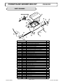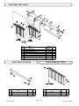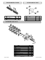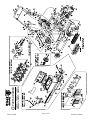
1
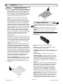
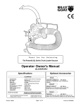
2
REPLACEMENT PARTS
1
FLAIL BLADES
P/N 350186.
A complete replacement set. 52
of our high quality flail blades for
your PR. Includes 8 new lock
clips for replacement installation.
FLAIL SHAFTS
P/N 350185.
A full set of four shafts for
replacement. Includes 8 new
lock clips for replacement
installation.
Note: We recommend
replacing the shafts when you
replace flails.
DRIVE BELT
P/N 350116.
Original Equipment drive belt for
your PR.
SPACER BUMPERS
P/N 350258.
A complete replacement set.
44 of 1/2" spacer bumpers
and 4 of 1/4" spacer bumpers
ACCESSORIES
SLICING REEL
P/N 350113.
A complete verti-slicing reel for
your PR. 20" wide reel for use
in grasses that require vertical
cutting, and for assisting in lawn
overseeding projects.
Thank You for Selecting
SLICING BLADES
The Powerful PR and OS
POWER RAKES and OVERSEEDERS
P/N 350187.
A full set of twenty blades for
replacement. Includes 40 new
capscrews, and lock nuts for
replacement installation.
Operator Owner's Manual
OVERSEEDER KIT
P/N 350325 / 350328.
The new light weight Plastic
Overseeding Kit is constructed
of durable High Density
Polypropolene with two lift
handles on each side to assist
in lifting the entire unit and easily
converts a PR Series Power
Rake into an overseeder with 4
bolts and minimal tools.
NOTE: Overseeder Conversion
Kit (350328) includes Slicing
Reel (350113). Part No.
(350325) comes with the
Overseeder Box only.
NEW
Part No. 350324
PR550, PR550H, PR550V,
PR550HV, OS551, OS551H
Specifications
3
PR550
PR550V
PR550H
PR550HV
OS551
OS551H
ENGINE: H.P.
5.5 (4.1 kW)
5.5 (4.1 kW)
5.5 (4.1 kW)
5.5 (4.1 kW)
5.5 (4.1 kW)
5.5 (4.1 kW)
ENGINE: TYPE
B&S OHV
B&S OHV
HONDA OHV
HONDA OHV
B&S OHV
HONDA OHV
ENGINE: FUEL CAP.
3.0 qt. (2.84 L)
3.0 qt. (2.84 L)
3.88 qt. (3.6 L)
3.88 qt. (3.6 L)
3.0 qt. (2.84 L)
3.88 qt. (3.6 L)
ENGINE: OIL CAP.
0.66 qt. (0.62 L)
0.66 qt. (0.62 L)
0.69 qt. (0.65 L)
0.69 qt. (0.65 L)
0.66 qt. (0.62 L)
0.69 qt. (0.65 L)
WEIGHT: UNIT
160# (72.5 kg)
163# (74.1 kg)
158# (71.8 kg)
161# (73.2 kg)
173# (78.5 kg)
171# (77.6 kg)
WEIGHT: SHIPPING
183# (83.0 kg)
183# (83.0 kg)
178# (80.9 kg)
178# (80.9 kg)
208# (94.3 kg)
209# (94.8 kg)
ENGINE WEIGHT:
36# (16.3 kg)
36# (16.3 kg)
34# (15.4 kg)
34# (15.4 kg)
36# (16.3 kg)
34# (15.4 kg)
MAX. ENGINE OPERATING SLOPE
15°
15°
20°
20°
15°
20°
Page 1 of 16
Form No. F031605A
5
IN THE INTEREST OF SAFETY
BEFORE STARTING ENGINE, READ AND UNDERSTAND THE “ENTIRE OPERATOR'S MANUAL & ENGINE MANUAL.”
THIS SYMBOL MEANS WARNING OR CAUTION. DEATH, PERSONAL INJURY AND/OR PROPERTY
DAMAGE MAY OCCUR UNLESS INSTRUCTIONS ARE FOLLOWED CAREFULLY.
WARNING: The Engine Exhaust from this product contains chemicals known
to the State of California to cause cancer, birth defects or other reproductive harm.
WARNING: DO NOT
13. DO NOT tamper with governor springs,
governor links or other parts which may
change the governed engine speed.
1. DO NOT run engine in an enclosed area.
Exhaust gases contain carbon monoxide, an
odorless and deadly poison.
14. DO NOT tamper with the engine speed
selected by the engine manufacturer.
2. DO NOT place hands or feet near moving
or rotating parts.
15. DO NOT check for spark with spark plug
or spark plug wire removed. Use an
approved tester.
3. DO NOT store, spill or use gasoline near
an open flame, or devices such as a stove,
furnace, or water heater which use a pilot
light or devices which can create a spark.
16. DO NOT crank engine with spark plug
removed. If engine is flooded, place throttle
in “FAST” position and crank until engine
starts.
4. DO NOT refuel indoors where area is not
well ventilated. Outdoor refueling is recommended.
17. DO NOT strike flywheel with a hard
object or metal tool as this may cause
flywheel to shatter in operation. Use proper
tools to service engine.
5. DO NOT fill fuel tank while engine is
running. Allow engine to cool for 2 minutes
before refueling. Store fuel in approved
safety containers.
6. DO NOT remove fuel tank cap while
engine is running.
18. DO NOT operate engine without a
muffler. Inspect periodically and replace, if
necessary. If engine is equipped with
muffler deflector, inspect periodically and
replace, if necessary, with correct deflector.
7. DO NOT operate engine when smell of
gasoline is present or other explosive
conditions exist.
19. DO NOT operate engine with an
accumulation of grass, leaves, dirt or other
combustible material in the muffler area.
8. DO NOT operate engine if gasoline is
spilled. Move machine away from the spill
and avoid creating any ignition until the
gasoline has evaporated.
20. DO NOT use this engine on any forest
covered, brush covered, or grass covered
unimproved land unless a spark arrester is
installed on the muffler. The arrester must
be maintained in effective working order by
the operator. In the State of California the
above is required by law (Section 4442 of
the California Public Resources Code).
Other states may have similar laws. Federal
laws apply on federal lands.
9. DO NOT transport unit with fuel in tank.
10. DO NOT smoke when filling fuel tank.
11. DO NOT choke carburetor to stop
engine. Whenever possible, gradually
reduce engine speed before stopping.
12. DO NOT run engine at excessive
speeds. This may result in injury & /or
damage to unit.
6
TABLE OF CONTENTS
SAFETY INSTRUCTIONS
2
3
GENERAL SAFETY
3
ASSEMBLY
4
CONTROLS
LABELS
4-5
OPERATION
6-9
10
MAINTENANCE
PARTS DRAWING & LIST... 14 - 15
TROUBLESHOOTING
16
WARRANTY PROCEDURE
16
○
○
○
○
○
○
○
○
○
○
○
○
○
○
○
○
○
○
○
○
○
○
○
○
○
○
○
○
○
○
○
○
○
○
○
Part No. 350324
○
○
○
○
○
23. DO NOT operate during excessive
vibration!
24. DO NOT leave machine unattended
while in operation.
25. DO NOT park machine on a steep grade
or slope.
WARNING: DO
1. ALWAYS DO remove the wire from the
spark plug when servicing the engine or
equipment TO PREVENT ACCIDENTAL
STARTING.
2. DO keep cylinder fins and governor
parts free of grass and other debris
which can affect engine speed.
3. DO pull starter cord slowly until resistance is felt. Then pull cord rapidly to avoid
kickback and prevent hand or arm injury.
4. DO examine muffler periodically to be
sure it is functioning effectively. A worn or
leaking muffler should be repaired or
replaced as necessary.
5. DO use fresh gasoline. Stale fuel can
gum carburetor and cause leakage.
6. DO check fuel lines and fittings frequently
for cracks or leaks. Replace if necessary
7. Follow engine manufacturer operating
and maintenance instructions.
8. Inspect machine and work area before
starting unit.
SOUND
7
8
VIBRATION
VIBRATION LEVELS 3.2 g max.
Sound tests conducted were in accordance with 2000/14/EEC
and were performed on 2/13/2002 under the conditions listed:
NOTE: Sound power level listed is the highest value for any model in this manual. Please
refer to serial plate on the unit for the sound power level for your model.
Vibration levels at the operators handles were
measured in the vertical, lateral, and longitudinal
directions using calibrated vibration test equipment.
Tests were performed on 09/08/97 under the
conditions listed:
Sound level of 82 dBA at operator position
GENERAL CONDITION:
Sunny
48° F (8.9° C)
TEMPERATURE:
○
○
○
22. DO NOT run engine without air cleaner
or air cleaner cover.
○
○
○
21. DO NOT touch hot muffler, cylinder, or
fins because contact may cause burns.
101 dB
(PR550 MODEL)
2 MPH (3.2 kmh)
WIND SPEED:
South East
WIND DIRECTION:
29 %
HUMIDITY:
GENERAL CONDITION:
TEMPERATURE:
WIND SPEED:
Sunny
85° F (29.4° C)
10 MPH (16.1 kmh)
WIND DIRECTION:
East
HUMIDITY:
31 %
○
BAROMETRIC PRESSURE:
30.34" Hg (770mm Hg)
Page 2 of 16
BAROMETRIC PRESSURE:
29.91" Hg (760mm Hg)
Form No. F031605A
GENERAL SAFETY
9
For your safety and the safety of others, these directions should be followed:
Do not operate this machine without first reading
owner's manual and engine manufacturer's manual.
Use of Ear Protection is recommended while
operating this machine.
Use of Eye and Breathing protection is recommended
when using this machine, especially in dry and dusty
conditions.
Wearing gloves is recommended while
operating this machine.
·DO NOT place hands or feet underneath unit, near debris
outlet or near any moving parts.
·DO NOT start engine without height adjust lever in up
position and clutch bail disengaged.
·DO NOT start or operate machine with guards removed.
·DO NOT perform any service on the unit without removing
the spark plug wire.
10
·DO NOT operate a machine that exhibits excessive vibration.
·DO NOT operate this machine on slopes greater than19°.
·DO NOT use this unit on any surface other than grass lawns.
·DO NOT allow children to operate this equipment.
-DO read all maintenance and operating instructions before begining
work.
-DO read all engine manufacturers operating and maintenance
instructions.
-DO inspect lawn before begining work. Remove all rocks, wire,
string, or other objects that can present a hazard during work prior to
starting.
-DO identify and mark all fixed objects to be avoided during work,
such as sprinkler heads, water valves, buried cables, or clothes line
anchors, etc.
ASSEMBLY
1. UNFOLD the upper handle (item 26) and slide handle lock
loops(item 28) into place to secure the upper handle to the lower.
2. CHECK engine oil level and fill to proper level with engine manufacturers recommended grade of oil. Move height adjust lever to down
position, to level engine during checking. See engine manufacturers
instruction manual.
3. CONNECT spark plug wire.
Read all safety and operating instructions
before assembling or starting this unit.
PUT OIL IN ENGINE BEFORE STARTING
Your Billy Goat Power Rake is shipped from the factory in one
carton, completely assembled.
11
PACKING CHECKLIST
These items should be included in your carton. If
any of these parts are missing, contact your dealer.
Engine
Manual Per
Model
Per Model
Check
Briggs & Stratton
5.5 Intek OHV
Check
Honda 5.5 OHV
26
Check
28
28
28
Owner's
Manual
350324
Check
Literature
Assembly
350110
Literature PR
Accessories
350140
Check
Warranty
Card 400972
Check
PR550, PR550H,
PR550V, & PR550HV
Part No. 350324
OS551 & OS551H
Page 3 of 16
EU Declaration
of Conformity &
EU Distributor
List 350139
Form No. F031605A
13
CONTROLS
HONDA ENGINE THROTTLE CONTROL
B & S ENGINE THROTTLE CONTROL
Set lever to choke position when
starting a cold engine
THROTTLE LEVER
RUN
CHOKE
STOP
FUEL VALVE
15
Set lever to desired engine speed.
Move lever completely to the left to stop
engine
CHOKE LEVER
ENGINE LABELS
Briggs & Stratton
ON
RUN
CHOKE
Read and follow Operating
Instructions before running engine.
OFF
Gasoline is flammable. Allow engine
to cool at least 2 minutes before fueling.
Engines emit carbon monoxide,
DO NOT run in enclosed area.
Honda
..
'
'
'
OIL ALERT
WHEN OIL LEVEL LOW,
ENGINE STOPS IMMEDIATELY.
Part No. 350324
Page 4 of 16
Form No. F031605A
INSTRUCTION LABELS
14
These labels should be included on your Power Rake. If any of these labels are damaged, replace them before putting this
equipment into operation. Item and part numbers are given to help in ordering replacement labels.
830503
BLADES UP
BLADES DOWN
Label Clutch Item 49
Part No.830503
BLADE DEPTH
ROTATE KNOB TO ADJUST BLADE DEPTH- 1
RELEASE TO DISENGAGE CLUTCH
PULL TO ENGAGE CLUTCH
2
3
4
5
6
400268
EXPLOSIVE FUEL
BLADES DOWN
OPERATING POSITION
BLADES UP
TRANSPORT POSITION
WARNING
CAUTION
STOP ENGINE AND ALLOW T O
COOL BEFORE REFUELING.
READ OWNERS MANUAL
BEFORE OPERATING
Label Do Not Fill While
Engine Is Hot
Item 50 Part No.400268
Label Danger Keep Hands
and Feet Away
Item 51 Part No.400424
USE PERSONAL
PROTECTION EQUIPMENT
PROTECT BYSTANDERS
FLYING DEBRIS
BEFORE STARTING, MAKE SURE:
HEIGHT ADJUST LEVER IS IN UP POSITION.
ALL GUARDS ARE ATTACHED.
DANGER
ALWAYS:
900327
810736
INSPECT MACHINE BEFORE EACH USE AND REPLACE ANY
WORN AND DAMAGED PARTS.
PROPERLY SECURE EQUIPMENT BEFORE TRANSPORTING.
DISCONNECT SPARK PLUG WIRE BEFORE SERVICING UNIT.
USE ONLY A QUALIFIED MECHANIC T O SERVICE THIS MACHINE.
Label Instructions Height Adjust
Item 35 Part No. 350176
Label Danger Flying Material
Item 48 Part No.810736
Label Danger Guard
Item 52 Part No.900327
LAWN PREPARATION:
350176
WARNING
FOR PREVENTATIVE MAINTENANCE
CHECK ENGINE OIL DAILY.
INSPECT AND CLEAN ENGINE AIR FILTER
DAILY. REPLACE AS NEEDED.
GREASE REEL BEARINGS AND LUBRICATE DEPTH
CONTROL LEVER EVERY ENGINE OIL CHANGE.
SEED APPLICATION CHART:
- MOW LAWN TO LOWEST SETTING ON YOUR MOWER.
THESE SETTINGS ARE APPROXIMATE GUIDELINES. SEEDING RATES ARE SPEED DEPENDENT.
FASTER TRAVEL DELIVERS LESS SEED.
- DO NOT WATER PRIOR TO SEEDING.
- POWER RAKE TO DETHATCH LAWN AND REMOVE THATCH.
- FERTILIZE LAWN WITH BROADCAST SPREADER.
SEED
RATE
STOP
SEED
RATE
STOP
TYPE
LBS
SETTING
TYPE
LBS
SETTING
1,000 FT 2
1,000 FT 2
SEEDING RECOMMENDATIONS:
1/2
1
- FOR BEST RESULTS OVERSEED IN TWO PASSES OF ONE-HALF
APPLICATION RATE AT RIGHT ANGLES OR IN A CRISS-CROSS PATTERN.
3/4
2
1 1/2
3
- WATER HEAVILY IMMEDIATELY THEN LIGHTLY FOR 10 - 14 DAYS
KEEPING SOIL MOIST.
2 1/3
4
RYEGRASS
- AFTER GERMINATION, WATER LESS OFTEN TO PROMOTE GROWTH.
0
1
2
3
4
5 6
7
- PULL BACK ON THE KNOB THEN
SLIDE THE BRACKET TO DESIRED
STOP SETTING.
EXAMPLE: STOP SETTING IS ON 4
STOP
SETTING
BRACKET
KNOB
BLUEGRASS
- IF SLICING WITHOUT DROPPING
SEEDS FOR LONG PERIOD OF TIME
THEN SET THE STOP SETTING TO
ZERO.
FESCUE
2/3
1
1 1/3
2
BERMUDAGRASS
3/4
1
(HULLED & ZOYSIA)
1 2/3
2
BENTGRASS
3/4
3
1
4
CENTIPEDEGRASS
2/3
1
1 1/2
5
(COATED)
1 1/4
2
2 1/2
6
2 1/2
3
3/4
5
ST. AUGUSTINE
3/4
3
1 1/4
6
GRASS
1
4
2
7
1 1/3
5
3 1/2
8
1 1/2
6
REFERENCE
CHART
BILLY
GOAT
SEEDER
SETTING
5
6
SCOTTS
SEEDER
SETTING
(ALL DROP
SEEDER
MODELS)
6 1/3
8
7
10
8
15 1/2
9
17
Label Instructions Seeder Box
Item 45 Part No. 350288
Part No. 350324
Page 5 of 16
Form No. F031605A
16
Operation
INTENDED USE: This machine is designed for removing
thatch from your lawn, renovation of existing lawns, and to
assist in overseeding operations. The machine should not
be used for any other purpose than that stated above.
ADJUSTING BLADE DEPTH
Do not operate if excessive vibration occurs. If excessive
vibration occurs, shut engine off immediately and check for
damaged or worn reel, loose pulley bolts or set screws, loose
engine or lodged foreign objects. (See trouble shooting
section on page 12).
Counter Clockwise:
To raise blades
Clockwise:
To lower
blades
Like all mechanical tools, reasonable care must
be used when operating machine.
Inspect machine work area and machine before operating. Make sure that all operators of this equipment are
trained in general machine use and safety.
STARTING ENGINE
ENGINE: See engine manufacturer’s instructions
for type and amount of oil and gasoline used.
Engine must be level when checking and filling oil and
gasoline.
ENGINE SPEED: Controlled by throttle lever on the engine.
Under normal conditions, operate at full throttle to accomplish your task.
FUEL VALVE: Move fuel valve to "ON" position (Honda
only).
The depth of the blades can be raised or lowered by
rotating the knob on the top of the adjustment lever. The
blades are lowered by rotating the knob clockwise, and
raised by rotating the knob counter-clockwise. The
relative depth of the blades can be gauged by using the
depth scale located on the right front corner of the engine
base. With new blades installed the depth can be
estimated as follows: 2.5 on the scale is even with the
ground, 3 is equal to 0.25" deep, and 3.5 is equal to 0.5"
deep
CHOKE: Operated with lever on the engine.
THROTTLE: Move throttle control on engine to fast position.
Pull starting rope to start engine.
IF YOUR UNIT FAILS TO START:
See Troubleshooting on page 12.
FOLDING HANDLE
BLADE POSITION & DEPTH CONTROL LEVER
The blades can be raised or lowered into the ground by
height adjusment lever on the engine base. The height
adjuster lock lever must be pushed back against the
adjustment lever in order to lower the blades into the
ground. The resulting blade depth can be adjusted higher
or lower.
See ADJUSTING BLADE DEPTH.
BLADES UP
TRANSPORT
This unit is equipped with a folding upper handle for easier storage
and transportation. The handle can be folded by sliding the handle
lock loops(item 28) up. This releases the upper handle, allowing it to
be folded over the unit.
BLADES UP
TRANSPORT
HANDLING & TRANSPORTING
This unit requires two people to lift it. With the handle in
the folded position, lift holding the lower handle and belt/
shaft guard one on each side of the machine. Secure
the machine in place during transport.
BLADES DOWN
RUNNING
Part No. 350324
Page 6 of 16
Form No. F031605A
OPERATION
16
Hints!
continued
RAKING/SLICING TIPS
Before begining, it is best to evaluate the condition of
the lawn by cutting one or more core samples from
area to be treated. A core can be cut using a piece of
pvc, or metal pipe. Hammer the pipe into the ground,
remove it, push the core out of the pipe and inspect it
to determine the depth of thatch in your yard.
THATCH: Thatch is a dense layer of dead grass,
clippings, and roots that builds up over time at the
base of of the lawn preventing air, water, and fertilizer
from reaching the soil. This can cause shallow root
development and make a lawn more susceptible to
drought and disease. Thatch also provides an ideal
environment for insects to hide and multiply. Periodic
removal of thatch will keep your lawn in good health.
HEAVY THATCH: Lawns with an excessive amount of
thatch will require multiple treatments for effective
removal. Trying to remove excessive thatch (greater
than 3/4"[19 mm] deep) in one treatment will damage
or destroy the living part of the lawn. It is best to
remove heavy thatch in seasonal treatments (i.e.
spring, and fall).
Fig. 2
RAKING OPERATION
DO NOT- Use this machine on any surface other than a
lawn.
DO NOT- Use this machine on slopes in excess of19°.
DO NOT- Allow persons unfamiliar with this equipment to
operate it.
DO NOT- Allow children to operate this equipment.
NOTE: Must have the flail reel assembly (350112) for
this operation.
SLOPES: Rake slopes across not up and down. This
is much easier and safer for the operator and is better
for the lawn. Raking across will help to reduce runoff
during watering and allow the sloped ground to hold
more seed, fertilizer, and water. The units maximum
operating slope is 35% or 19°.
DEPTH: The wide range of depth adjusment on your
unit is provided to allow for blade wear. Setting the
reel deeper will not produce better, or quicker results.
The flail reel is intended to be set so it just touches the
surface on flat ground. The slicing reel should be set
even with the ground for verti-slicing work, and set to a
maximum 1/2" depth for overseeding jobs. Setting the
reel deeper than this will only result in premature wear
on the unit (i.e. failed belt). If you desire to work the
ground deeper than the above guidlines allow, it
should be done gradually in multiple passes..
SLICING / OVERSEEDING: Mow the lawn to shorter
than the normal cut height before starting (i.e. approximately 2" tall for fescue grass). For the best result,
Slice/Overseed in criss cross pattern (See Fig. 1 and
See Fig 2).
MOW: Mow the lawn to it's normal cut height.
DRY: Be sure grass is dry. Wet conditions can cause
increased damage to healthy grass.
SET DEPTH: With engine off, set the raking depth so that
the blades just touch on a flat surface (i.e. driveway, or
sidewalk).
START ENGINE: See page 5 for further instruction.
ENGAGE BLADES: Pull back on the bail on the operators handle. NOTE: When engaging the blades in heavy
load conditions (i.e. heavy thatch, or very uneven turf),
push down on the operators handle lifting the front
wheels slightly. Engage the blades. Slowly lower the unit
into the turf.
RAKE: Rake a small test area and examine the results.
Thatch should be removed and deposited on top of the
healthy grass. If excessive damage occurs to healty
grass, adjust the blade depth to decrease damage.
Continue raking the yard, working in one direction (i.e.
north-south, or east-west). NOTE: If a large drop in
engine RPM occurs, or the unit pulls you forward and
bounces during operation the blade depth is set too low.
Fig. 1
Part No. 350324
REMOVE THATCH: After raking, a layer of thatch will be
deposited over the top of the lawn. This thatch must be
removed prior to any fertilizing, seeding, or watering of
the lawn. We suggest the use of a lawn vacuum or
wheeled blower for collection and removal of the thatch.
Page 7 of 16
Form No. F031605A
16
OPERATION
continued
VERTI-CUTTING OPERATION
OVERSEEDING OPERATION
DO NOT- Use this machine on any surface other than a
lawn.
DO NOT- Use this machine on slopes in excess of 19°.
DO NOT- Allow persons unfamiliar with this equipment to
operate it.
DO NOT- Allow children to operate this equipment.
DO NOT- Use this machine on any surface other than a
lawn.
DO NOT- Use this machine on slopes in excess of 19°.
DO NOT- Allow persons unfamiliar with this equipment to
operate it.
DO NOT- Allow children to operate this equipment.
NOTE: Must have the slicing reel assembly (350113) for
this operation.
NOTE: Must have the slicing reel assembly (350113) for
this operation.
MOW: Mow the lawn to shorter than the normal cut height
(approximately 2" tall)
MOW: Mow the lawn to shorter than the normal cut
height (approximately 2" tall)
DRY: Be sure grass is dry. Wet conditions can cause increased damage to healty grass.
DRY: Be sure grass is dry. Wet conditions can cause
increased damage to healthy grass.
SET DEPTH: With engine off, set the raking depth so that the
blades just touch on a flat surface (i.e. driveway, or sidewalk).
SEED: Spread grass seed according to the seed
suppliers directions (e.g. 10 lbs. per 1000 ft2 [4.5 kg. per
93 m2 ])
START ENGINE: See Page 5.
ENGAGE BLADES: Pull back on the bail on the operators
handle. NOTE: When engaging the blades in heavy load
conditions (i.e. heavy thatch, or very uneven turf), push down
on the operators handle lifting the front wheels slightly.
Engage the blades. Slowly lower the unit into the turf.
SLICE: Verti-cut a small test area and examine the results.
Some thatch and cut stems should be removed and deposited
on top of the healthy grass. Grass runners should be cut and
ready for removal. If excessive damage occurs to healthy
grass, adjust the blade depth to decrease damage. Continue
raking the yard, working in one direction (i.e. north-south, or
east-west). NOTE: If a large drop in engine RPM occurs, or
the unit pulls you forward and bounces during operation the
blade depth is set too low.
REMOVE THATCH/STEMS: After verti-cutting, a layer of
thatch and cut stems will be deposited over the top of the lawn.
We suggest the use of a lawn vacuum or wheeled blower for
collection and removal of the thatch/stems.
SET DEPTH: With engine off, set the raking depth so
that the blades reach 1/4"-1/2"(6-12 mm) below a flat
surface (i.e. driveway, or sidewalk).
START ENGINE: See Page 5.
ENGAGE CLUTCH: Pull back on the bail on the
operators handle. NOTE: When engaging the clutch in
heavy load conditions (i.e. heavy thatch, or very
uneven turf), push down on the operators handle lifting
the front wheels slightly. Engage the clutch. Slowly
lower the unit into the turf.
SLICE: Run machine over the area that has been
seeded to incorporate the seed into the soil. If excessive damage occurs to healthy grass, adjust the blade
depth to decrease damage. Continue raking the yard,
working in one direction (i.e. north-south, or east-west).
NOTE: If a large drop in engine RPM occurs, or the unit
pulls you forward and bounces during operation the
blade depth is set too low.
WATER/FERTILIZE: After the seed has been worked
into the soil, water and fertilize according to the seed
suppliers directions.
Part No. 350324
Page 8 of 16
Form No. F031605A
OPERATION
16
continued
ADJUSTING SEED RATE
STOP
SETTING
BRACKET
DROPPING SEEDS
- PULL BACK ON THE KNOB THEN
SLIDE THE BRACKET TO DESIRED
STOP SETTING.
EXAMPLE: STOP SETTING IS ON 4
- IF SLICING WITHOUT DROPPING
SEEDS FOR LONG PERIOD THEN SET
THE STOP SETTING TO ZERO . OF
TIME.
KNOB
LAWN PREPARATION
- MOW LAWN TO LOWEST SETTING ON YOUR MOWER.
- DO NOT WATER PRIOR TO SEEDING.
- POWER RAKE TO DETHATCH LAWN AND REMOVE
THATCH.
- FERTILIZE LAWN WITH BROADCAST SPREADER.
- AFTER ADJUSTING THE STOP SETTING, LIFT UP ON THE BAR TO OPEN
THE DROP SEEDER DOOR.
LAWN PREPARATION
- FOR BEST RESULTS OVERSEED IN TWO PASSES OF
ONE-HALF
APPLICATION RATE AT RIGHT ANGLES OR IN A CRISSCROSS PATTERN.
- WATER HEAVILY IMMEDIATELY THEN LIGHTLY FOR 10 14 DAYS
KEEPING SOIL MOIST.
- AFTER GERMINATION, WATER LESS OFTEN TO
PROMOTE GROWTH.
- TO STOP DROPPING SEEDS, PUSH FORWARD ON THE HANDLE TO
CLOSE THE DROP SEEDER DOOR.
NOTE: IF SLICING WITHOUT DROPPING SEEDS FOR LONG PERIOD OF
TIME THEN SET THE STOP SETTING TO ZERO .
SEED APPLICATION CHART:
THESE SETTINGS ARE APPROXIMATE GUIDELINES. SEEDING RATES ARE SPEED DEPENDENT.
FASTER TRAVEL DELIVERS LESS SEED.
SEED
RATE
STOP
SEED
RATE
STOP
TYPE
LBS
SETTING
TYPE
LBS
SETTING
1,000 FT2
RYEGRASS
BLUEGRASS
FESCUE
Part No. 350324
1,000 FT2
1/2
1
3/4
2
1 1/2
3
2 1/3
4
BENTGRASS
2/3
1
1 1/3
2
BERMUDAGRASS
3/4
1
(HULLED & ZOYSIA)
1 2/3
2
3/4
1
3
4
CENTIPEDEGRASS
2/3
1
1 1/2
5
(COATED)
1 1/4
2
2 1/2
6
3/4
5
1 1/4
2
6
7
3 1/2
8
2 1/2
3
ST. AUGUSTINE
3/4
3
GRASS
1
1 1/3
4
5
1 1/2
6
Page 9 of 16
REFERENCE
CHART
BILLY
GOAT
SEEDER
SETTING
SCOTTS
SEEDER
SETTING
5
6 1/3
8
6
(ALL DROP
SEEDER
MODELS)
7
10
8
15 1/2
9
17
Form No. F031605A
17
MAINTENANCE
ROTATING FLAIL REEL END TO END
Use only a qualified mechanic for
any adjustments, disassembly or
any kind of repair .
To maximize flail blade life and performance the reel can be rotated
end to end periodically to provide a fresh lead cutting edge. Takes
approx. 20 min. and requires 1/2" and 9/16" socket wrenches with
extension bar.
WARNING: TO AVOID PERSONAL INJURY, ALWAYS
TURN MACHINE OFF, MAKE SURE ALL MOVING
PARTS COME TO A COMPLETE STOP.
1. Wait for engine to cool and disconnect spark plug.
2. Close fuel valve on engine (if available).
3. Lean unit back onto lower handles and secure in place.
DISCONNECT SPARK PLUG WIRE
BEFORE SERVICING UNIT.
4. Remove (6) lock nuts(item 62) holding the belt and shaft guards(item
21 &22) in place. It is necessary to lower the height adjust lever to reach
the locknuts on the guards. Remove the guards.
5. Remove the drive belt(item 9) by "walking" it out of the groove on the
reel pulley(item 2).
ENGINE: See engine manufacturer
operator's instructions.
6. Remove the (4) lock nuts(item 60) and washers(item 68) holding the
bearings(item 23) to the frame of the unit.
RECONNECT SPARK PLUG WIRE,
AND ALL GUARDS, BEFORE
STARTING ENGINE.
7. The reel is now free from the machine. Slide the reel down and out of
the machine.
8. Remove the capscrew(item 71), lockwasher(item 57), reel pulley(item
2), key(item 42), and reel spacer(item 10) from the end of the reel.
9. Rotate the reel end to end, and re-install these items on the opposite
end of the reel.
USE ONLY BILLY GOAT ORIGINAL
EQUIPMENT PARTS FOR
REPLACEMENT AND REPAIR
10. Re-install the reel in reverse order of removal. Re-install the guards
in reverse order of removal.
BLADE WEAR AND ROTATING REEL END TO END
DRIVE BELT REPLACEMENT
FLAIL BLADE WEAR
NOTE: Takes approx. 10 min. and requires 1/2" socket wrench with
extension.
1. Wait for engine to cool and disconnect spark plug.
1. Wait for engine to cool and disconnect spark plug.
2. Close fuel valve on engine (if available).
3. Lean unit back onto lower handles and secure in place.
4. Inspect blades for wear, and immediately replace any bent or
cracked blades. Measure the overall length of the blade. (See fig. 1)
5. If blades measure less than 3.25"(83 mm) in overall length they
must be replaced. NOTE: We recommend replacing all the flails at
once.
2 . Remove (3) lock nuts(item 62) holding the belt guard(item 21) in
place. It is necessary to lower the height adjust lever to reach the
locknuts on the guard. Remove the guard.
3. Remove the belt(item 9) by rotating the reel pulley(item 2) and
walking it out of the groove. Discard old belt
4. Install new belt using same procedure to walk the belt into the
groove.
5. With new belt installed pull bail rod back to engaged position and
measure extension of idler spring. Spring should stretch 3/4" - 1" (19
25 mm) with bail engaged. Adjust clutch cable as necessary to achieve
this extension.
6. Re-install the belt guard.
Maintenance Schedule
Maintenance Operation
Follow these hourly
maintenance intervals.
Every Use
(Daily)
Every
25 hrs
Engine (See Engine Manual)
Fig. 1
Check engine oil
Inspect and clean engine air filter
SLICING BLADE WEAR
1. Wait for engine to cool and disconnect spark plug.
2. Close fuel valve on engine (if available).
3. Lean unit back onto lower handles and secure in place.
4. Inspect blades for wear, and immediately replace any bent or
cracked blades. Measure the overall length of the blade from the center
of the attachment bolt to the tip of the worn blade.
5. If blades measure less than 3"(76 mm) in length they must be
replaced. NOTE: We recommend replacing all the blades at once.
Part No. 350324
Grease reel bearings
Inspect belt
Inspect for loose, worn,
or damaged parts
Oil height adjustment linkage
Page 10 of 16
Form No. F031605A
POWER RAKE SEEDER BOX KIT
P/N 350325
PARTS DRAWING
PART S LIST
ITEM NO.
1
2
3
4
5
6
7
8
9
10
11
12
13
14
15
16
17
18
19
21
22
24
25
26
28
29
30
PART NO.
350321
350306
350276
350320
350271
350272
350273
350322
350319
8171003
900321
350335
400217
8024040
8024021
350286
8160001
350332
8160002
350318
350280
350329
8197031
350331
8172007
8154007
8059136
DESCRIPTION
BOX PLASTIC DROP SEEDER MAIN BODY
BRACKET ADJ DROP SEEDER ASSY
BAR DOOR LINKGAGE
SHAFT PLASTIC DROOP SEEDER
PLATE DOOR DROP SEEDER
PLATE DOOR DROP SEEDER END
PLATE DOOR DROP SEEDER ARM
BOX PLASTIC DROP SEEDER LID ASSEMBLY
SPROCKET 16T #43 0.625 BORE
W ASHER 5/16 FLAT CUT
BEARING CLIP 1.375 OD
GUARD SPROCKET
SPRING TENSION
BOLT CARRAIGE 5/16 - 18 X 1
BOLT CARRIAGE 1/4-20 X 3/4"
SCREW SHEET METAL
NUT LOCK 1/4
BRACKET SLOT PLASTIC SEEDER BOX
NUT LOCK 5/16
SPROCKET W HEEL 16T
W ASHER 0.906 OD X 0.656 ID
CHAIN 35 PITCH
PIN COTTER 1/8" X 1"
ROLL PIN 1/8 - 1 3/4
W ASHER 1/4 SAE
NUT HEX 10-24
SCREW CAP #10-24 X 3/4
QTY
1
1
1
1
1
1
1
1
1
1
4
1
2
1
1
4
1
1
1
1
4
1
1
1
1
2
2
PART S BAG SEEDER BOX KIT
15
17
19
20
23
27
28
31
32
-
Part No. 350324
8024021
8160001
8160002
8177011
8041026
8172020
8172007
8171006
8161044
350327
BOLT CARRIAGE 1/4-20 X 3/4"
NUT LOCK 1/4
NUT LOCK 5/16 (REQUIRE ON THE OLD MODELS ONLY)
W ASHER LOCK 5/16
SCREW CAP 5/16-18 x 3/4
W ASHER 5/16 FENDER
W ASHER 1/4 SAE
W ASHER 1/2 FC
NUT LOCK 1/2" THIN HGT
LIT SEEDER BOX (INCLUDES TEMPLATE)
Page 11 of 16
2
2
4
4
4
4
2
3
1
1
Form No. F031605A
FLAIL REEL ASSY 350112
item
no.
73
74
75
76
77
78
79
PARTS
LIST
SHAFT FLAIL BLADE
BLADE FLAIL
SPACER BUMPER 5/8" x 1/4"
SPACER BUMPER 5/8" x 1/2"
SHAFT WA FLAIL REEL
CLIP LOCK 1/2"
WASHER 1/2 SAE
FLAIL SHAFT KIT 350185
PARTS
ite m
no.
LIST
73 SHA FT FLA IL BLA DE
78 CLIP LOCK 1/2"
Part No. 350324
QTY
4
52
4
44
1
8
8
FLAIL BLADE KIT 350186
Par t No. QTY
350141
350146
PR500
Part No.
350141
350100
350143
350144
350145
350146
8172011
PARTS
item
no.
LIST
74 BLADE FLAIL
78 CLIP LOCK 1/2"
4
8
Page 12 of 16
Part No. QTY
350100
350146
52
8
Form No. F031605A
SPACER BUMPER KIT 350258
PARTS
item
no.
LIST
75 SPACER BUMPER 5/8" x 1/4"
76 SPACER BUMPER 5/8" x 1/2"
PR500
Part No.
350143
350144
SLICING BLADE KIT 350187
QTY
item
no.
4
44
81
85
86
PARTS
LIST
BLADE SLICING REEL
SCREWCAP 1/4-20 x 3/4, GR. 5
NUT LOCK 1/4-20
PR500
Part No.
350147
350151
8142004
QTY
20
40
40
SLICING REEL ASSY 350113
item
no.
57
71
80
81
82
83
84
85
86
87
88
89
90
Part No. 350324
PARTS
LIST
LOCK WASHER 5/16 TWISTED TOOTH
SCREWCAP 5/16 - 24 x 1" HCS GR. 5
SHAFT SLICING WA
BLADE SLICING REEL
PLATE BLADE MTG.
SPACER BLADE MTG.
SPACER BLADE ASSY
SCREWCAP 1/4-20 x 3/4, GR. 5
NUT LOCK 1/4-20
COLLAR SPACER
WASHER 0.937 x 1.750 x 0.119
WASHER LOCK 7/8 INT. TOOTH
NUT JAM 7/8-14
Page 13 of 16
PR500
Part No.
800177
400164
350142
350147
350148
350149
350150
350151
8142004
350152
350153
350154
350155
QTY
1
1
1
20
20
10
9
40
40
1
1
1
1
Form No. F031605A
Part No. 350324
Page 14 of 16
Form No. F031605A
PARTS DRAWING
PR550, PR550V, PR550H
PR550HV, OS551, OS551H
18
Part No. 350324
Page 15 of 16
item
no.
1
1A
2
3
4
5
6
7
8
9
10
11
12
13
14
15
16
17
18
19
20
21
22
23
24
25
26
27
28
29
30
31
32
33
34
35
36
37
38
39
40
41
Form No. F031605A
42
42A
43
44
45
46
47
48
49
50
51
52
53
54
55
56
57
58
59
60
PARTS
PR550
LIST
Part No.
Pulley 3" OD
350101-01
Spacer Crank PR Honda
Pulley 6.5" OD X ¾"
350102
Wheel 8" Front PR
350103
Wheel 10" Front PR
350104
Height Adjust Assy
350107
Reel Flail / Slicing Assy
350112
Pulley Idler 2.75"
350114
Arm Idler WA
350115
Belt 5L X 36
350116
Spacer Reel Pulley
350118
Bracket Mount Clutch Cable
350119
Chassis WA W/ Label
350194
Frame Front WA
350121
Bushing 0.375 OD X 0.256 ID X 0.88
350309
Spring Height Adjust PR500
350125
Link Height Adjust PR500
350126
Yoke ½ - 20
350127
Pin Yoke ½"
350128
Bracket Mount Hgt. Adj. WA
350182
Spacer Spanner Wheel PR500
350130
Guard Belt WA W/ Label
350195
Guard Shaft WA W/ Label
350196
Bearing ¾" Cast Pillow Block
350133
Handle Lower LH WA
350134
Handle Lower RH WA
350135
Handle Upper PR500
350136
Bail Clutch WA
350137
Loop Folding Handle
350138
Deflector Rubber
350167
Shield Bearing
350168
Bar Clamp Deflector
350171
Bracket Height Adjust Lock WA
350173
Guard Pulley Back
350184
Lever Height Control
350175
Label Instr. Hgt. Adj.
350176
Bolt Shoulder ¼" x 1 ¾"
350178
Bolt Shoulder 5/16" x 1 ¾"
350179
Cable Clutch Reel PR500
350181
Spring Extension
400217
Bolt Shoulder 1/2" X 1"
500114
ENGINE HONDA 5.5 H.P. GX160
ENGINE INTEK 5.5HP OHV B&S
350197
KEY 3/16" X 1"
9201078
KEY 1/4" x 1"
9201113
GRIP 1" x 13"
400570
GRIP LEVER 1/8 x 1 x 5"
500181
LABEL INSTRUCTION SEEDER BOX
WASHER 5/16 FC (BELT GUARD)
8171003
LABEL GOAT HEAD
850209
LABEL DANGER THROWN OBJECT
810736
LABEL CLUTCH VQ
830503
LABEL HOT ENGINE
400268
LABEL WARNING
400424
LABEL DANGER GUARD
900327
PLUG CAP 1" RD
890132
BOLT CARRAIGE 3/8-16 x 1 3/4
8024061
BOLT CARRAIGE 5/16-18 x 1 3/4
8024043
BOLT CARRIAGE 5/16 -18 x 3/4
8024039
LOCK WASHER TW. TOOTH
400502
NUT LOCK #10-24
8164005
NUT LOCK 1/4-20
8160001
NUT LOCK 3/8-16
8160003
QTY
PR550H
1
1
2
2
1
1
1
1
1
1
1
1
1
1
1
1
1
1
1
4
1
1
2
1
1
1
1
2
1
2
1
1
1
1
1
1
1
1
1
3
1
1
1
2
1
2
1
1
1
1
2
1
2
4
2
4
1
1
2
9
Part No.
350101
350339
350102
350103
350104
350107
350112
350114
350115
350116
350118
350119
350194
350121
350309
350125
350126
350127
350128
350182
350130
350195
350196
350133
350134
350135
350136
350137
350138
350167
350168
350171
350173
350174
350175
350176
350178
350179
350181
400217
500114
600115
9201078
400570
500181
850209
810736
830503
400268
400424
900327
890132
8024061
8024043
8024039
400502
8164005
8160001
8160003
QTY
OS551
PR550V
1
1
1
2
2
1
1
1
1
1
1
1
1
1
1
1
1
1
1
1
4
1
1
2
1
1
1
1
2
1
2
1
1
1
1
1
1
1
1
1
3
1
2
2
1
1
1
1
1
2
1
2
4
2
4
1
1
2
9
Part No.
350101-01
350102
350103
350104
350107
350113
350114
350115
350116
350118
350119
350194
350121
350309
350125
350126
350127
350128
350182
350130
350195
350196
350133
350134
350135
350136
350137
350138
350167
350168
350171
350173
350184
350175
350176
350178
350179
350181
400217
500114
350197
9201078
9201113
400570
500181
350288
8171003
850209
810736
830503
400268
400424
900327
890132
8024061
8024043
8024039
800177
8164005
8160001
8160003
QTY
OS551H
PR550HV
1
1
2
2
1
1
1
1
1
1
1
1
1
1
1
1
1
1
1
4
1
1
2
1
1
1
1
2
1
2
1
1
1
1
1
1
1
1
1
3
1
1
1
2
1
1
2
1
1
1
1
2
1
2
4
2
5
1
1
5
9
Part No.
350101
350339
350102
350103
350104
350107
350113
350114
350115
350116
350118
350119
350194
350121
350309
350125
350126
350127
350128
350182
350130
350195
350196
350133
350134
350135
350136
350137
350138
350167
350168
350171
350173
350174
350175
350176
350178
350179
350181
400217
500114
600115
9201078
400570
500181
350288
850209
810736
830503
400268
400424
900327
890132
8024061
8024043
8024039
800177
8164005
8160001
8160003
QTY
1
1
1
2
2
1
1
1
1
1
1
1
1
1
1
1
1
1
1
1
4
1
1
2
1
1
1
1
2
1
2
1
1
1
1
1
1
1
1
1
3
1
2
2
1
1
1
1
1
1
2
1
2
4
2
5
1
1
5
9
3
19
1
1
3
4
8
8
5
4
1
-
OS551H
PR550HV
Part No.
8161042
8160002
8041008
8041051
8042026
8172015
430298
8041030
8171003
8171004
8171006
8161044
400164
-
-
-
-
SLICING REEL ASSEMBLY (FOR PR550V, PR550HV, OS551, AND OS551H MODELS ONLY)
80 SHAFT SLICING WA
350142
1
350142
1
350142
81 BLADE SLICING REEL
350147
20
350147
20
350147
82 PLATE BLADE MTG.
350148
20
350148
20
350148
83 SPACER BLADE MTG.
350149
10
350149
10
350149
84 SPACER BLADE ASSY
350150
9
350150
9
350150
85 SCREWCAP 1/4-20 x 3/4, GR. 5
350151
40
350151
40
350151
86 NUT LOCK 1/4-20
8142004
40
8142004
40
8142004
87 COLLAR SPACER
350152
1
350152
1
350152
88 WASHER 0.937 x 1.750 x 0.119
350153
1
350153
1
350153
89 WASHER LOCK 7/8 INT. TOOTH
350154
1
350154
1
350154
90 NUT JAM 7/8-14
350155
1
350155
1
350155
1
20
20
10
9
40
40
1
1
1
1
350142
350147
350148
350149
350150
350151
8142004
350152
350153
350154
350155
1
20
20
10
9
40
40
1
1
1
1
SEEDER BOX ASSEMBLY (FOR OS551, AND OS551H MODELS ONLY)
91 BOX SEEDER MAIN BODY
92 BRACKET ADJ DROP SEEDER
93 BAR DOOR LINKGAGE
94 SHAFT PLASTIC DROOP SEEDER
95 PLATE DOOR DROP SEEDER
96 PLATE DOOR DROP SEEDER END
97 PLATE DOOR DROP SEEDER ARM
98 BOX SEEDER LID ASSEMBLY
99 SPROCKET 16T #43 0.625 BORE
101 BEARING CLIP 1.375 OD
102 GUARD SPROCKET
103 SPRING TENSION
104 BOLT CARRAIGE 5/16 - 18 X 1
105 BOLT CARRIAGE 1/4-20 X 3/4"
106 SCREW SHEET METAL
108 BRACKET SLOT SEEDER
109 SPROCKET WHEEL 16T
110 WASHER 0.906 OD X 0.656 ID
111 CHAIN 35 PITCH
112 COTTER PIN 1/8 - 1"
113 ROLL PIN 1/8 - 1 3/4
114 WASHER 5/16 FENDER
115 WASHER LOCK 5/16
116 SCREWCAP 5/16-18 x 3/4
117 WASHER 1/4" SAE
118 NUT HEX 10-24
119 SCREW 10-24 X 3/4
-
1
1
1
1
1
1
1
1
1
4
1
2
1
3
4
1
1
4
1
1
1
4
4
4
3
2
2
350321
350306
350276
350320
350271
350272
350273
350322
350319
900321
350335
400217
8024040
8024021
350286
350332
350318
350280
350329
8197031
350331
8172020
8177011
8041026
8172007
8154007
8041026
1
1
1
1
1
1
1
1
1
4
1
2
1
3
4
1
1
4
1
1
1
4
4
4
3
2
2
item
no.
61
62
63
64
65
65A
65B
66
67
68
69
70
71
72
PARTS
LIST
NUT LOCK 3/8-16 THIN
NUT LOCK 5/16-18
SCREWCAP 1/4-20 x 1 1/2
SCREWCAP 3/8 - 16 x 1 1/4
SCREWCAP 5/16-24 x 3/4" GR.5
Washer 3/4 SAE
Washer 5/16 Twist Tooth
SCREWCAP 5/16 - 18 x 1 1/2
WASHER 5/16 FLAT CUT
WASHER 3/8 FLAT CUT
WASHER 1/2 FC
NUT LOCK 1/2" - 13 THIN HGT
SCREWCAP REEL PULLEY
BUTTON SOCKET 5/16-18X5/8”
PR550
Part No.
8161042
8160002
8041008
8041051
8042026
8041030
8171003
8171004
8171006
8161044
8041050
350266
QTY
3
18
1
1
3
4
4
8
2
4
1
4
PR550H
Part No.
8161042
8160002
8041008
8041051
8042026
8172015
430298
8041030
8171003
8171004
8171006
8161044
8041050
350266
FLAIL REEL ASSEMBLY (FOR PR550 AND PR550H MODELS ONLY)
73 SHAFT FLAIL BLADE
350141
4
350141
74 BLADE FLAIL
350100
52
350100
75 SPACER BUMPER 5/8" x 1/4"
350143
4
350143
76 SPACER BUMPER 5/8" x 1/2"
350144
44
350144
77 SHAFT WA FLAIL REEL
350145
1
350145
78 CLIP LOCK 1/2"
350146
8
350146
79 WASHER 1/2 SAE
8172011
8
8172011
3
18
1
1
4
1
1
4
4
8
2
4
1
4
OS551
PR550V
Part No.
8161042
8160002
8041008
8041051
8042026
8041030
8171003
8171004
8171006
8161044
400164
-
4
52
4
44
1
8
8
-
QTY
-
350321
350306
350276
350320
350271
350272
350273
350322
350319
900321
350335
400217
8024040
8024021
350286
350332
350318
350280
350329
8197031
350331
8172020
8177011
8041026
8172007
8154007
8041026
QTY
QTY
3
19
1
1
4
1
1
4
8
8
5
4
1
-
20
TROUBLESHOOTING
Before Requesting Service Review These Suggestions
Solution
Possible Cause
Problem
Engine stalls or labors when raking.
Blades set too deep into ground
Raise blades so that they just touch the ground on a
level surface.
Abnormal vibration.
Damaged or missing blades. Loose handle bolts.
Loose engine bolts
Stop work immediately. Replace any damaged or
missing blades. Tighten all loose bolts and nuts.
Engine will not start.
Stop switch off (Honda only). Throttle in off position.
Engine not in full choke position. Out of gasoline. Bad
or old gasoline. Spark Plug wire disconnected. Dirty air
cleaner. Engine oil level too low (Honda only).
Check stop switches, throttle, choke position and
gasoline. Connect spark plug wire. Clean or replace
air cleaner. Contact a qualified service person.
Engine is locked, will not
pull over.
Debris locked against reel, or drive pulleys. Engine
problem.
Pull spark plug wire and remove debris. Contact an
engine servicing dealer for engine problems.
UNIT STORAGE
ENGINE
Never store engine indoors or in enclosed poorly ventilated
areas with fuel in tank, where fuel fumes may reach an open flame,
spark or pilot light, as on a furnace, water heater, clothes dryer or
other gas appliance.
GENERAL ENGINE SPECIFICATIONS
GOVERNED RPM
ENGINE
HORSEPOWER
BRIGGS &
STRATTON
MODEL NO.
5.5
1104020191E1
3700
HONDA
5.5
GX160K1QX
3600
When servicing engine refer to specific manufacturers engine
owner's manual. All engine warranty is covered by the specific
engine manufacturer. If your engine requires warranty or other
repair work contact your local servicing engine dealer. When
contacting a dealer for service it is a good idea to have your engine
model number available for reference(See table page above). If
you can not locate a servicing dealer in your area you can contact
the manufacturers national service organization.
If engine is to be unused for 30 days or more, prepare as follows:
Remove all gasoline from carburetor and fuel tank to prevent
gum deposits from forming on these parts and causing possible
malfunction of engine. Drain fuel outdoors, into an approved
container, away from open flame. Be sure engine is cool. Do not
smoke. Run engine until fuel tank is empty and engine runs out of
gasoline.
NOTE: Fuel stabilizer (such as Sta-Bil) is an acceptable alternative in minimizing
the formation of fuel gum deposits during storage. Add stabilizer to gasoline in
fuel tank or storage container. Always follow mix ratio found on stabilizer
container. Run engine at least 10 min. after adding stabilizer to allow it to reach
the carburetor.
To reach:
Briggs & Stratton: 800-233-3723
American Honda: 800-426-7701
Engine Service and Warranty
22.1
WARRANTY PROCEDURE
22
Contact your nearest engine manufacturer's
authorized servicing dealer. (See page 7)
Should a Billy Goat Machine fail due to a defect in material and/or
workmanship, the owner should make a warranty claim as follows:
21
Serial Plate
Record your machine model, serial number
-The Machine must be taken to the dealer from whom it was purchased
or to an authorized Servicing Billy Goat Dealer.
-The owner must present the remaining half of the Warranty
Registration Card, or, if this is not available, the invoice or receipt.
-The Warranty Claim will be completed by the authorized Billy Goat
Dealer and submitted to their respective Billy Goat Distributor for their
territory. Attention: Service Manager. Any parts replaced under
warranty must be tagged and retained for 90 days.
-The distributor service manager will sign off on the claim and submit
it to Billy Goat for consideration.
-The Technical Service Department at Billy Goat will study the claim
and may request parts to be returned for examination. Billy Goat will
notify their conclusions to the distributor service manager from whom
the claim was received.
-The decision by the Quality / Service department at Billy Goat to
approve or reject a Warranty claim is final and binding.
and date-of-purchase and where purchased
1803 S. Jefferson
Lee's Summit,
MO 64062 / USA
Tel (816) 524-9666
Fax (816) 524-6983
R
Model
Serial No.
101 dB
Unit(Weight)
lbs.
Engine Power
kg
kW
rpm
min-1
Note: To process a Warranty Claim, it is necessary to quote the Model & Serial
Number which are printed on the Billy Goat Serial Plate (See owner’s manual).
Purchase
Date
Part No. 350324
Purchased
from
R
Page 16 of 16
BILLY GOAT INDUSTRIES INC.
1803 S.W. JEFFERSON / LEE'S SUMMIT, MO 64082-2312 / USA
PHONE: 816-524-9666 FAX: 816-524-6983
www.billygoat.com
Form No. F031605A