1
APPLYING: NORMAL OPERATION - NO. 2 OR
SECONDARY CIRCUIT
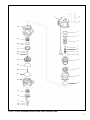
When the primary inlet valve (29) is moved off its seat, air is
permitted to pass through the bleed passage and enters the
relay piston cavity. The air pressure moves the relay piston
(24), which contains the exhaust seat, and closes the
secondary exhaust valve. As the secondary exhaust valve
closes, the inlet valve (19) is moved off its seat allowing the
secondary air to flow out the delivery of the same circuit.
Because of the small volume of air required to move the
relay piston (24), action of the secondary circuit of the valve
is almost simultaneous with the primary circuit portion.
APPLYING: LOSS OF AIR IN THE NO. 2 OR
SECONDARY CIRCUIT
Should air be lost in the No. 2 or secondary circuit, the No.
1 or primary circuit will continue to function as described
above under Normal Operation: No.1 or Primary Circuit
Portion.
APPLYING: LOSS OF AIR IN THE NO. 1 OR
PRIMARY CIRCUIT
Should air be lost in the primary circuit, the function will be
as follows: As the brake treadle is depressed and no air
pressure is present in the primary circuit supply and delivery
ports, the primary piston (11) will mechanically move the
relay piston (24) , allowing the piston to close the secondary
exhaust valve and open the secondary inlet valve and allow
air to flow out the secondary delivery port.
BALANCED: NO. 1 OR PRIMARY CIRCUIT
When the primary delivery pressure acting on the primary
piston (11) equals the mechanical force of the brake pedal
application, the primary piston (11) will move and the primary
inlet valve (29) will close, stopping further flow of air from the
primary supply line through the valve. The exhaust valve
remains closed preventing any escape of air through the
exhaust port.
BALANCED: NO. 2 OR SECONDARY CIRCUIT
When the air pressure on the delivery side of the relay piston
(24) approaches that being delivered on the primary side of
the relay piston, the relay piston moves closing the
secondary inlet valve and stopping further flow of air from the
supply line through the valve. The exhaust remains closed
as the secondary delivery pressure balances the primary
delivery pressure.
When applications in the graduating range are made, a
balanced position in the primary circuit is reached as the air
pressure on the delivery side of the primary piston (11) equals
the effort exerted by the driver's foot on the treadle. A balanced
position in the secondary portion is reached when air pressure
on the secondary side of the relay piston (24) closely
approaches the air pressure on the primary side of the relay
piston.
When the brake treadle is fully depressed, both the primary
and secondary inlet valves remain open and full reservoir
pressure is delivered to the actuators.
RELEASING: NO. 1 OR PRIMARY CIRCUIT
With the brake treadle released, mechanical force is removed
from the spring seat (5), graduating spring (6), and primary
piston (11). Air pressure and spring load moves the primary
piston, opening the primary exhaust valve, allowing air
pressure in the primary delivery line to exhaust out the
exhaust port.
RELEASING: NO. 2 OR SECONDARY CIRCUIT
With the brake treadle released, air is exhausted from the
primary circuit side of the relay piston (24). Air pressure and
spring load move the relay piston, opening the secondary
exhaust valve, allowing air pressure in the secondary delivery
line to exhaust out the exhaust port.
PREVENTIVE MAINTENANCE
Important: Review the Bendix Warranty Policy before
performing any intrusive maintenance procedures. A warranty
may be voided if intrusive maintenance is performed during
the warranty period.
No two vehicles operate under identical conditions, as a
result, maintenance intervals may vary. Experience is a
valuable guide in determining the best maintenance interval
for air brake system components. At a minimum, the
E-10PR™ valve should be inspected every 6 months or 1500
operating hours, whichever comes first, for proper operation.
Should the E-10PR™ valve not meet the elements of the
operational tests noted in this document, further investigation
and service of the valve may be required.
Visually check for physical damage to the brake valve such
as broken air lines and broken or missing parts.
Every 3 months, 25,000 miles, or 900 operating hours:
Clean any accumulated dirt, gravel, or foreign material away
from the heel of the treadle, plunger boot, and mounting
plate.
Lubricate the treadle roller, roller pin, and hinge pin, with
Barium grease per BW-204-M (Bendix part 246671).
Check the rubber plunger boot for cracks, holes or
deterioration and replace if necessary. Also, check mounting
plate and treadle for integrity.
Apply a thin layer of Barium grease, per BW-204-M (Bendix
part 246671), between plunger and mounting plate – do not
over oil!
3